

Pump Ends
(Series 20FS, 30FS, 40FB, 50FB, 50FB-U-U,
50FB-U-M, 60FB, FB50, FB75, FB100, 80FC)
Installation, Operation and
Service Maintenance Manual
Hale Products Inc. ◆ A Unit of IDEX Corporation
700 Spring Mill Avenue
Telephone: 610-825-6300
Web......www.haleproducts.com
◆ Conshohocken, PA 19428 U.S.A.
◆ FAX: 610-825-6440
Manual p/n: 029-0020-61-0
NOTICE !
Hale Products, Inc. cannot assume responsibility for product failure resulting from
improper maintenance or operation. Hale is responsible only to the limits stated in
the product warranty. Product specifications contained in this manual are subject
to change without notice.
All Hale products are quality components -- ruggedly designed, accurately
machined, precision inspected, carefully assembled and thoroughly tested. In
order to maintain the high quality of your unit, and to keep it in a ready condition, it
is important to follow the instructions on care and operation. Proper use and good
preventive maintenance will lengthen the life of your unit.
ALWAYS INCLUDE THE UNIT SERIAL NUMBER
IN YOUR CORRESPONDENCE.
ECN No REV CHANGE FROM BY DATE APVD
0592 A INITIAL RELEASE LwH 06/11/2007 MAL
HALE PRODUCTS, INC.
A Unit of IDEX Corporation
Conshohocken, PA 19428 USA
Manual p/n: 029-0020-61-0, Rev. -A
Printed in U.S.A.
WRITTEN BY LwH ISSUE DATE COPYRIGHT ©
CHECKED BY PW 06/11/2007
NOT TO BE REPRODUCED OR USED TO
MAKE OTHER DRAWINGS OR MACHINERY.
© Hale Products, Inc. 2007
All Rights Reserved

Table of Contents ❑
Contents Page
Pump Ends, Pumping Systems
1 Safety Precautions................................................................................................. 11
1.1 Definitions.........................................................................................................................12
1.2 General ..............................................................................................................................13
1.3 Fuel Safety ........................................................................................................................ 16
1.4 Battery Safety ................................................................................................................... 17
2 Overview ................................................................................................................ 19
2.1 Pump Ends ....................................................................................................................... 19
Figure 2-1: Typical Pump End Pumping Systems ..............................................................19
20FS-2M / 20FS-3M / 20FS-4M Series, with Gearbox ..............................................................19
30FS2 / 30FS3 / 30FS4 Series, with Gearbox ...........................................................................20
40FB / 50FB Series, Bell Housing or Pedestal Mount (-U-U Series) .........................................20
FB50 / FB75 / FB100 Series, Bell Housing Mount .....................................................................20
60FBG Series, with Gearbox .....................................................................................................21
60FJ Series, Bell Housing Mount...............................................................................................21
80FC Series, Bell Housing Mount..............................................................................................21
80FC (-G or -U) Series, with gearbox (-G) or pedestal (-U) .......................................................21
2.2 Pumping System Overview .............................................................................................22
Figure 2-2: Typical 20FS Series Pump System Overview..................................................23
Figure 2-3: Typical 30FS Series Pump System Overview..................................................24
Figure 2-4: Typical 40 / 50FB Series Pump System Overview...........................................25
Figure 2-5: Typical FB50, FB75 and FB100 Series Engine Mount
Pump End Overview.......................................................................................26
Figure 2-6: Typical 60FBG Series Pump System Overview...............................................27
Figure 2-7: Typical 80FC Series Pump System Overview..................................................28
Figure 2-8: Typical 80FC-U Series Pedestal Pump System Overview...............................29
Figure 2-9: Check Valve Option, Discharge .......................................................................30
2.3 Principles of Operation ................................................................................................... 31
Centrifugal Force ..............................................................................................................................31
Figure 2-10: Centrifugal Force - Rotating Disk ...................................................................31
Figure 2-11: Pump Water Flow, Cutwater ..........................................................................32
2.4 Pump Components .......................................................................................................... 32
Volute, Pump Body...........................................................................................................................32
Figure 2-12: Typical Pump and Gearbox Overview............................................................33
Impeller.............................................................................................................................................33
Figure 2-13: Impeller Operation..........................................................................................33
Clearance Rings ...............................................................................................................................34
Pump Ends
p/n: 029-0020-61-0
3

❑ Table of Contents
Contents - continued Page
2.4 Pump Components - continued
Mechanical Seal ...............................................................................................................................34
Figure 2-14: Typical Mechanical Seal Overview ................................................................ 34
Ball Bearings ....................................................................................................................................35
2.5 Gearbox Option................................................................................................................ 35
2.6 Pedestal Mounting Option .............................................................................................. 35
Figure 2-15: Pedestal Mount .............................................................................................. 35
2.7 Hale Engine Mount Bell Housing.................................................................................... 36
Figure 2-16: Bell Housing Mount........................................................................................ 36
2a Accessories / Options.............................................................................................37
2a.1 Anodes.............................................................................................................................. 37
Figure 2a-1: Hale 1-1/4” NPT Anode..................................................................................37
2a.2 Auxiliary Cooling ............................................................................................................. 38
Gearbox Manifold Coolers ............................................................................................................... 38
Figure 2a-2: Typical Gearbox Manifold Coolers................................................................. 38
Heat Exchanger, “K” Series.............................................................................................................. 38
2a.3 Pressure and Relief Valve Control ................................................................................. 38
Figure 2a-3: Model “K” Heat Exchanger ............................................................................. 39
P Series Relief Valve System........................................................................................................... 39
Figure 2a-4: P Series Relief Valve Control.........................................................................39
Thermal Relief Valves (TRV)............................................................................................................ 39
Figure 2a-5: Thermal Relief Valve, TRV............................................................................. 40
TRV-L Kit ...................................................................................................................................40
2a.4 Priming Systems.............................................................................................................. 41
Figure 2a-6: Rotary Vane ESP Priming Pump ................................................................... 41
Priming Valves.................................................................................................................................. 41
Figure 2a-7: SPVR Priming Valves .................................................................................... 42
Figure 2a-8: PVG Priming Valves.......................................................................................42
2a.5 Pump Shift, Automatic (VPS / KPS) ............................................................................... 42
Figure 2a-9: Automatic Pump Shift Overview..................................................................... 43
Figure 2a-10: Pump Shift Control Valve............................................................................. 43
2a.6 Torrent SVS Valves..........................................................................................................44
Figure 2a-11: Typical SVS Valve Primary Components.................................................... 44
3 Basic Operation ..................................................................................................... 45
3.1 Overview ........................................................................................................................... 45
3.2 Fluid Levels ...................................................................................................................... 45
3.3 Preparing to Tow.............................................................................................................. 46
4
Pump Ends
p/n: 029-0020-61-0

Table of Contents ❑
Contents - continued Page
3.4 Pumping Operations ........................................................................................................ 46
Initial Start Up ...................................................................................................................................46
Pumping Operations .........................................................................................................................47
Figure 3-1: Typical Portable Pump Installation...................................................................47
Draft Operation Limiting Factors.......................................................................................................49
3.5 Relief Valve Procedures .................................................................................................. 50
Standard Relief Valve Procedures....................................................................................................50
TPM Relief Valve Procedures...........................................................................................................50
Figure 3-2: TPM / PMD Relief Valve Control......................................................................51
3.6 Post Operation Procedures.............................................................................................51
4 Preventive Maintenance ....................................................................................... 53
4.1 Overview ........................................................................................................................... 53
Preventive / General Maintenance ...................................................................................................53
Engine........................................................................................................................................53
Skid and/or Trailer......................................................................................................................54
Pump, Gearbox and Pedestal ....................................................................................................54
Accessories................................................................................................................................54
4.2 Post-Operation ................................................................................................................. 54
4.3 Extreme Conditions ......................................................................................................... 55
During Freezing Weather..................................................................................................................55
4.4 Weekly ............................................................................................................................... 55
Gearbox Option ................................................................................................................................56
To Check / Add Oil.....................................................................................................................56
Figure 4-1: Typical Drain, Fill and Level Plugs ...................................................................57
Pedestal Option ................................................................................................................................57
To Check / Add Oil.....................................................................................................................57
Figure 4-2: Typical Pedestal Oil Servicing..........................................................................58
Check / Add Engine Fluids ...............................................................................................................58
Relief Valve Test...............................................................................................................................58
Governor Test...................................................................................................................................59
Priming System.................................................................................................................................59
Valve Maintenance ...........................................................................................................................59
Verify All Gauges are in Working Order............................................................................................60
Intake Strainers.................................................................................................................................60
Inspect Water and Foam Tanks........................................................................................................60
Operate Pump Controls ....................................................................................................................60
4.5 Monthly.............................................................................................................................. 60
Valve Lubrication ..............................................................................................................................61
Check Gearbox or Pedestal Lubrication ...........................................................................................61
Pump Ends
p/n: 029-0020-61-0
5

❑ Table of Contents
Contents - continued Page
4.5 Monthly - continued
Pump and Flange Bolts ....................................................................................................................61
Priming System Test (Dry Vacuum Test) ......................................................................................... 61
Figure 4-3: PVG Priming Valve Handle.............................................................................. 61
4.6 Annually............................................................................................................................ 62
Pump Head Bearing Lubrication....................................................................................................... 63
Figure 4-4: Pump Head Bearing Lubrication ...................................................................... 63
Change Gearbox Oil ......................................................................................................................... 63
Change Pedestal Oil......................................................................................................................... 64
Relief Valve System Check ..............................................................................................................65
Check Drain Lines to Multi-Drain ......................................................................................................65
Clean Priming Pump.........................................................................................................................66
Performance Testing Overview ........................................................................................................ 66
Figure 4-5: Pump Ratings (GMP/LPM)...............................................................................66
Tank-to-Pump Flow Rate Test.......................................................................................................... 67
Performance Testing Equipment and Materials................................................................................ 67
Performance Testing ........................................................................................................................68
Worn Clearance Rings and Impeller Hubs ....................................................................................... 69
Anode Check ..................................................................................................................................70
Figure 4-6: Hale Anode ...................................................................................................... 70
5 Troubleshooting.....................................................................................................71
5.1 Engine and Trailer............................................................................................................ 71
5.2 Pump ................................................................................................................................. 71
Figure 5-1: Sample, Serial Nameplate ............................................................................... 71
Figure 5-2: Troubleshooting Chart...................................................................................... 71
Pump Loses Prime or Will Not Prime. .............................................................................. 71
Insufficient Pump Capacity. ..............................................................................................73
Insufficient Pressure. ........................................................................................................ 74
Remote Control Difficult to Operate..................................................................................74
Engine Speeds Too HIGH for Required Capacity or Pressure.........................................74
Cavitation.......................................................................................................................... 75
Relief Valve Does Not Relieve Pressure When Relief Valves are Closed. ...................... 75
Relief Valve Does Not Recover and Return to Original Pressure
Setting After Opening Valves. .................................................................................... 76
Relief Valve Opens When Control Valves are Locked Out. .............................................76
Unable to Obtain Proper Setting on Relief Valves............................................................ 76
Discharge Valves Are Difficult to Operate. .......................................................................76
Water/Moisture in Pump Gearbox. ...................................................................................77
Rotation Symptoms. ......................................................................................................... 77
6
Pump Ends
p/n: 029-0020-61-0

Table of Contents ❑
Contents - continued Page
6 Repair..................................................................................................................... 79
6.1 Overview ........................................................................................................................... 79
6.2 General Repair Guidelines .............................................................................................. 79
Before You Begin..............................................................................................................................79
Table 6-1: Typical Torque Values Chart .............................................................................81
Gearbox and Pedestal Assemblies................................................................................................... 82
6.3 Cleaning and Inspection Guidelines .............................................................................. 82
Bearings............................................................................................................................................83
Tools Required ................................................................................................................................. 83
6a Servicing the Pump ............................................................................................... 85
6a.1 General Preparation.........................................................................................................85
6a.2 20FS Series Pump Only................................................................................................... 85
Bearing Housing ............................................................................................................................... 85
Figure 6a-1: 20FS Series, Pump and Bearing Housing Overview......................................86
Removing the Pump .........................................................................................................................87
Pump Body (Halves) ..................................................................................................................87
Impellers (2) ...............................................................................................................................87
Mechanical Seal – 20FS Series Pump Only .............................................................................. 88
Installation Notes – Pump Body and Impellers ..........................................................................88
Oil Seal, Pump Shaft ........................................................................................................................89
Figure 6a-2: Oil Seal, Pump Shaft ......................................................................................89
Installation – Pump Head ...........................................................................................................90
6a.3 All other Pumps................................................................................................................ 90
Suction Flange..................................................................................................................................90
Figure 6a-3: Typical Suction Flange Option .......................................................................91
Installation Notes – Suction Flange............................................................................................91
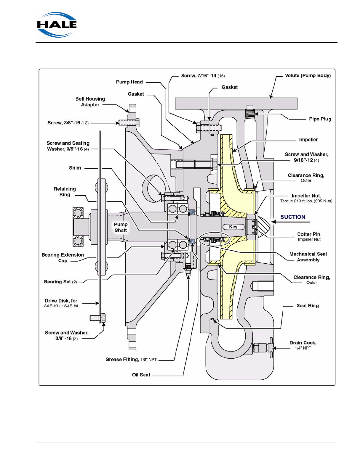
Volute (Pump Body)..........................................................................................................................91
Figure 6a-4: Typical Pump Disassembly Overview............................................................92
Installation Notes – Volute (Pump Body) ................................................................................... 93
Impeller.............................................................................................................................................94
For 30 FS series pump...............................................................................................................94
For all other pump models .........................................................................................................94
Figure 6a-5: Placing Edges for Impeller Removal ..............................................................95
Clearance Rings, Impeller Measurement .........................................................................................95
Figure 6a-6: Clearance Ring and Impeller ID / OD Measurement......................................96
Installation Notes – Impeller ............................................................................................................. 96
6a.4 Pump Shaft Oil Seals, with Bell Housing....................................................................... 97
Pump Head Assembly – 30 FS Series Only .....................................................................................98
Pump Ends
p/n: 029-0020-61-0
7

❑ Table of Contents
Contents - continued Page
Pump Head Assembly – 30 FS Series Only - continued
Pump Shaft Oil Seal, 30 FS Series............................................................................................98
Figure 6a-7: Replacing 30 FS Series Pump Shaft Oil Seal................................................ 98
Installation Notes – Pump Head, 30 FS Series.........................................................................99
Bell Housing (Flywheel) Adapter, FB40 – FB100 Series Only........................................................99
Pump Shaft Oil Seal, 40 – 100 FB Series.................................................................................. 99
Figure 6a-8: Replacing 40FB - 100FB Series Pump Shaft Oil Seal .................................100
Pump Shaft Bearings, FB40 – FB100 Series...........................................................................101
Installation Notes – Pump Head, FB40 – FB100 Series .........................................................101
Bell Housing (Flywheel) Adapter, 80 FC Series Only.................................................................... 102
Pump Shaft Oil Seal, 80 FC Series Only ................................................................................. 102
Figure 6a-9: Replacing 80 FC Series Pump Shaft Oil Seal .............................................. 103
Pump Shaft Bearings, 80 FC Series Only................................................................................ 104
Installation Notes – Bell Housing Adapter, 80 FC Series Only ...............................................104
6a.5 Pump Shaft Oil Seals, with Pedestal Mount................................................................ 105
Pedestal Mount, Pump Shaft Oil Seals ......................................................................................... 105
Figure 6a-10: Pedestal Mount Pump Shaft Oil Seals (2),
40 / 5- FB-U and 80 FC-U Series ............................................................. 106
Pump Shaft Bearings............................................................................................................... 108
Installation Notes – Pedestal .................................................................................................. 108
6a.6 Pump Shaft Oil Seals, with Gearbox............................................................................ 109
6b Mechanical Seal Assembly.................................................................................. 111
6b.1 Removing the Seal......................................................................................................... 111
Figure 6b-1: Typical Mechanical Seal Assembly.............................................................. 111
6b.2 Installing Seal................................................................................................................. 112
Figure 6b-2: Typical Mechanical Seal Insertion Tool........................................................ 113
Impeller and Volute Installation Notes............................................................................................ 113
6c Gearbox Service................................................................................................... 115
6c.1 General Preparation....................................................................................................... 115
6c.2 20 / 30 FSG Series Gearbox .......................................................................................... 116
Removing the Gearbox and Bell Housing ......................................................................................116
Figure 6c-1: 20 / 30 FS Series Gearbox and Bell Housing Overview............................... 117
Drive Shaft Oil Seal ........................................................................................................................ 118
Drive Shaft and Gearbox Assembly ...............................................................................................118
Pump Shaft.....................................................................................................................................119
Gearbox Installation Notes – 20 / 30 FS Series ............................................................................. 119
6c.3 50 / 60 / 80 FBG Series Gearbox................................................................................... 120
Pump Shaft and Shaft Oil Seal .......................................................................................................120
Figure 6c-2: Pump Shaft Oil Seal, 50/60/80 FBG Series, with Gearbox ..........................121
8
Pump Ends
p/n: 029-0020-61-0

Table of Contents ❑
Contents - continued Page
6c.3 50 / 60 / 80 FBG Series Gearbox - continued
Installation Notes – Pump Shaft and Seal, 50/60/80 FBG..............................................................122
Gearbox and Bell Housing Assemblies ..........................................................................................123
Bell Housing (Flywheel) Adapter..............................................................................................123
Drive Shaft Oil Seal..................................................................................................................123
Figure 6c-3: Gearbox and Bell Housing Overview,
50/60/80 FBG Series Pump End ...............................................................124
Gearbox, Intermediate and Drive Shafts..................................................................................125
Installation Notes – Gearbox and Bell Housing, 50/60/80 FBG..................................................... 126
7 Installation ........................................................................................................... 127
7.1 Overview ......................................................................................................................... 127
7.2 Frame Mounting .............................................................................................................127
General Mounting ........................................................................................................................... 128
7.3 Plumbing Connections ..................................................................................................128
7.4 Fluid Levels..................................................................................................................... 128
7.5 Check Flywheel Run Out ............................................................................................... 129
S.A.E. Housing Pilot Bore............................................................................................................... 129
S.A.E. Housing Mounting Face....................................................................................................... 130
Flywheel Pilot Bearing Bore............................................................................................................130
Drive Disk Pilot Bore.......................................................................................................................130
Drive Disk Mounting Face...............................................................................................................130
Appendix A: Glossary......................................................................................... 131
Appendix A-1: Measurements ........................................................................... 135
Conversion Chart ...........................................................................................................135
Appendix C: Alternate Lubricant Manufacturers .......................................... 137
Table C-1: Alternate Lubricant Manufacturers..................................................................137
Appendix C1: Lube and Sealant Specifications .............................................. 139
Table C1-2: Oil Capacity and Recommendation ..............................................................139
Grease............................................................................................................................................140
Loctite Sealant................................................................................................................................ 140
Oil ................................................................................................................................................... 140
Recommended Cleaners ................................................................................................................140
Appendix D: Hose Friction Loss ....................................................................... 141
Table D-1: Hose Friction Loss (PSI / BAR 100 Feet) ....................................................... 141
Pump Ends
p/n: 029-0020-61-0
9

❑ Table of Contents
Contents - continued Page
Appendix E: Nozzle Size vs. Pressure................................................................ 143
Chart E-1: Nozzle Flow and Pressure Ratings, Part 1 ..................................................... 143
Chart E-2: Nozzle Flow and Pressure Ratings, Part 2 ..................................................... 144
Appendix F: Cavitation....................................................................................... 145
Figure F-1: Sample, Cavitation Regions........................................................................... 145
Process of Cavitation......................................................................................................................145
Warning Signs of Cavitation (Discharge and Gauges) ................................................................... 146
Discharge Pressure .................................................................................................................146
Vacuum Compound Gauge ..................................................................................................... 146
To Eliminate Cavitation................................................................................................................... 146
During Operations ......................................................................................................................... 147
Figure F-2: Lift Loss from Temperature............................................................................147
Figure F-3: Lift Loss from Elevation.................................................................................. 147
Figure F-3a: Lift Loss from Barometric Reading............................................................... 147
Preventive Measures...................................................................................................................... 147
Figure F-4: Hose Size vs. Pump Rating Capacity ............................................................148
Express Warranty ............................................................................................... 149
Hale Products, Inc. ........................................................................................................................ 150
8 Drawing Package................................................................................................. 151
Pump Ends ..............................................................................................................................152
Available Options..................................................................................................................... 152
10
Pump Ends
p/n: 029-0020-61-0
1 Safety Precautions
HALE PUMP ENDS (SERIES 20* THROUGH 80*) ENGINE MOUNTED PUMPING
SYSTEMS ARE DESIGNED FOR OPTIMUM SAFETY OF ITS OPERATORS.
FOR ADDED PROTECTION, PLEASE FOLLOW THE SAFETY GUIDELINES
LISTED IN THIS SECTION AND ADHERE TO ALL WARNING, DANGER, CAUTION AND IMPORTANT NOTES FOUND WITHIN THIS MANUAL.
ALL SUPPLIED DOCUMENTATION (ENGINE, HALE PUMP MANUALS, ETC.)
MUST BE CAREFULLY READ, UNDERSTOOD AND ADHERED TO STRICTLY
BY ALL INSTALLERS AND OPERATORS BEFORE ATTEMPTING TO INSTALL
OR OPERATE ANY PUMPING SYSTEM.
WHEN DEVELOPING DEPARTMENTAL APPARATUS OPERATING PROCEDURES, INCORPORATE THE WARNINGS AND CAUTIONS AS WRITTEN.
Safety ❑
IMPORTANT !
Hale is a registered trademark of Hale Products, Incorporated. All other brand and product
names are the trademarks of their respective holders.
* For a breakdown of the models/series pump ends in this manual, see
heading “Pump Ends ” on page 19.
NOTICE !
THE PROCEDURES IN THIS MANUAL ARE GENERAL OPERATING PROCEDURES. THEY DO NOT REPLACE THE PROCEDURES, POLICIES OR GUIDELINES ESTABLISHED BY THE AUTHORITY HAVING JURISDICTION, NOR DO
THEY REPLACE THE RECOMMENDATIONS AND PROCEDURES PROVIDED
IN THE APPARATUS MANUFACTURER'S MANUAL.
REFER TO THE PROCEDURES PROVIDED BY THE AUTHORITY HAVING
JURISDICTION FOR UNIT LAYOUT AND CONNECTION OF HOSES, VALVES
AND DRAIN COCKS.
ALL FASTENERS ON THE PUMP END ASSEMBLIES ARE SELECTED FOR
THEIR APPLICATION. CLASS1 DOES NOT RECOMMEND REPLACING FASTENERS WITH ANYTHING OTHER THAN CLASS1 PART NUMBERS PROVIDED. REPLACING WITH A WEAKER ALTERNATIVE POSES A SERIOUS
SAFETY RISK.
Pump Ends
p/n: 029-0020-61-0
ALL FASTENERS MUST BE INSTALLED WITH A LOCKING ANAEROBIC
ADHESIVE / SEALANT, SUCH AS LOCTITE
®
#242, #246 OR EQUIVALENT.
11
❑ Safety
NOTICE ! - continued
ALSO REVIEW THE SAFETY INFORMATION FOUND IN THE ENGINE MANUFACTURER’S OPERATING AND MAINTENANCE MANUAL, PROVIDED WITH
THE ENGINE.
1.1 DEFINITIONS
DANGER - Immediate hazard which WILL result in severe personal injury or
death if the warning is ignored.
DANGER !
WARNING !
WARNING - Hazards or unsafe practices which COULD result in severe
personal injury or death if the warning is ignored.
CAUTION !
CAUTION - Hazards or unsafe practices which COULD result in minor or
moderate personal injury if the warning is ignored.
NOTICE !
NOTICE - Practices which could result in damage to the apparatus or other
property.
Carbon Monoxide Poisoning Hazard
12
Corrosive Hazard
Electrical Shock Hazard
Pump Ends
p/n: 029-0020-61-0
Eye Protection required when operating equipment
Flammable Fuel Hazard
Hearing Protection required when operating equipment
Hot Surfaces Hazard
1.2 GENERAL
Safety ❑
Read all instructions, including the Engine Manufacturer’s Operating
and Maintenance Manual, thoroughly before beginning
any installation, service or operation process.
❑ Use care when removing the pump assembly from its packaging to pre-
vent personal injury and/or damage to the system.
❑ Use all mounting bolt holes provided on the gearbox, pedestal and/or the
pump to support the assembly. See the appropriate assembly plate
drawing, located at the back of this manual, for additional installation
information.
❑ Installation should be performed by a trained and qualified installer, such
as your authorized Hale representative. Be sure the installer has sufficient knowledge, experience and the proper tools before attempting any
installation.
WARNING !
THE HALE PUMP ENDS, GEARBOX OR PEDESTAL ASSEMBLIES (IF
INCLUDED) CAN BE HEAVY AND BULKY. ADDING ACCESSORIES TO THE
SYSTEM ALSO INCREASES THE WEIGHT. CHECK YOUR BILL OF LADING
FOR THE APPROXIMATE WEIGHT.
Pump Ends
p/n: 029-0020-61-0
BE CERTAIN TO USE PROPER LIFTING SUPPORT DEVICES (I.E., OVERHEAD CRANE, JACKS, CHAINS, STRAPS, ETC.) CAPABLE OF HANDLING
THE LOAD WHEN REMOVING OR INSTALLING THE HALE PUMP END
ASSEMBLY.
13
❑ Safety
❑ The installer is responsible for observing all instructions and safety pre-
❑ Fluids - To meet various shipping regulations, oil is drained from the
❑ When mounting pumping system on a skid, truck, trailer or other movable
❑ DO NOT run the engine in a closed-in area. Proper ventilation for engine
cautions in his or her daily routine as dictated by regional safety ordinances or departmental procedures.
gearbox (or pedestal unit) reservoir prior to shipping from the factory.
At installation and before operation, oil must be added to the appropriate
levels. (See Section 4, heading “ Replace Gearbox Oil,” on page 59.)
For pedestal fluid fill / replacement, see heading “Change Pedestal Oil”
on page 64.
See separate documentation provided with the engine for proper fluids to
use and quantities required.
equipment, it is preferred to have the resting points under the frame as
close as possible under the frame cross-members. This prevents undo
strain on the frame and engine.
cooling and engine exhaust MUST BE provided.
❑ If an exhaust extension is required to vent gases to the outside, it is
important to construct the exhaust extension to prevent excessive
exhaust back pressure.
WARNING !
EXHAUST GASES CONTAIN CARBON MONOXIDE, WHICH IS AN ODORLESS
AND DEADLY POISON. PROPER EXHAUST VENTILATION MUST BE PROVIDED TO PREVENT THE ACCUMULATION OF EXHAUST GASES.
❑ The exhaust system components may smoke during the initial break-in
period. This smoking should stop after the pump is run several times.
❑ Be careful not to touch the exterior of a HOT engine, especially the muf-
fler and the surrounding area. The engine is hot enough to be painful or
cause burns / injury.
❑ DO NOT permanently remove or alter any protective feature, guard or
insulating devices, or attempt to operate the system when these guards
are removed.
❑ Do not run the engine with the covers removed.
14
Doing so voids the Hale pump warranty. Also see heading “Express
Warranty” on page 149.
Pump Ends
p/n: 029-0020-61-0

Safety ❑
WARNING!
NO MODIFICATIONS MAY BE MADE TO THE HALE PUMP END ASSEMBLY
WITHOUT PRIOR WRITTEN PERMISSION FROM:
Hale Products, Incorporated
Fire Suppression Division
700 Spring Mill Avenue
Conshohocken, PA 19428 U.S.A.
Telephone ..........610-825-6300
Fax .....................610-825-6440
Web....................www.haleproducts.com
❑ Any of the preceding could affect system capacity and/or safe operation
of the system and is a serious safety violation which could cause personal injury or could affect safe operation of the pump.
❑ Make sure proper personal protective equipment is used when operating
or servicing the apparatus.
WARNING!
BE SURE TO WEAR SAFETY GLASSES WHEN REMOVING AND/OR INSTALLING FORCE (PRESS) FITTED PARTS. WEAR PROTECTIVE, HEAT-RESISTANT GLOVES WHEN HANDLING PARTS THAT REQUIRE HEATING FOR
INSTALLATION AND/OR REMOVAL. FAILURE TO COMPLY MAY RESULT IN
SERIOUS EYE OR HAND INJURY.
DO NOT OVERHEAT PARTS CONSTRUCTED OF BRONZE (E.G. IMPELLER).
OVERHEATING (PART TURNS RED OR BLUE) CAN WEAKEN THE PART AND
IT MUST THEN BE REPLACED.
❑ DO NOT operate the system at pressures higher than the maximum
rated pressure. Always use the lowest possible relief valve settings to
enhance operator and equipment safety. Also see Section 2 “Introduction” on page 17 for additional information.
❑ Relieve all system pressure, then drain all water from the system before
servicing any of its component parts.
Pump Ends
p/n: 029-0020-61-0
❑ Use only pipe, hose and fittings which are rated at or above the maxi-
mum pressure rating at which the water pump system operates.
❑ Per NFPA 1962 requirements, large diameter hose, marked “supply
Hose 3-1/2” to 5” (89 - 127 mm) diameter” shall not be used at operating
pressures exceeding 185 PSI (13 BAR).
15
❑ Safety
❑ If leakage from the drain hole in the pump head is noticed or suspected,
❑ If a pump is operated without water for extended periods, or without dis-
❑ Keep equipment, i.e., engine controls and linkage, cylinder fins, muffler,
❑ Prevent accidental starting by always removing the battery ground (neg-
Large diameter hose, marked “Supply Hose 6” to 5” (152 mm) diameter”
shall not be used at operating pressures exceeding 135 PSI (9 BAR).
the mechanical seal must be inspected and/or replaced.
charging water, it could overheat. This can damage the mechanical seal,
impeller or the drive mechanism.
etc. and surrounding area clean. Cluttered areas invite accidents and
could effect engine operation.
Remove all oil deposits from equipment and surrounding area. Accumulations of grease and oil may present a hazard.
ative —) wire (BLACK) before working on the engine or the equipment
driven by the engine.
❑ Maximum speed of the engine is factory set. DO NOT tamper with the
governor springs, links or other parts to run at higher speeds. Excessive
speed increases the hazard of personal injury and reduces engine life.
❑ Familiarize yourself with all controls, learn how to STOP the engine
quickly in an emergency.
❑ DO NOT reduce the pressure on the INTAKE gauge below zero (0).
Serious damage to the water main could result.
❑ Use only PAC-EASE Rubber Lubricant Emulsion (or equal) on the rubber
mechanical seal parts to ease installation. DO NOT use other lubricant
types as damage to the mechanical seal and seat could occur.
❑ Before connecting any cord sets or wiring harnesses, inspect the seal
washer in the connector.
If the seal washer is missing or damaged, water can enter the connector
causing corrosion. This could resulting in possible system failure.
1.3 FUEL SAFETY
❑ Carefully read and understand the “Engine Manufacturer’s Operating
and Maintenance Instructions” before attempting to operate, service or
disassemble the engine or any of its parts. Also see Section 4 “Operation” on page 27.
16
WARNING !
POSITIVELY NO SMOKING !!
Pump Ends
p/n: 029-0020-61-0
Safety ❑
WARNING ! - continued
❑ Gasoline is a highly combustible fuel. The improper use, handling or
storage of gasoline can be dangerous. Prevent accidents by following
these safety recommendations, plus those furnished by your regional
safety ordinances or departmental procedures:
● Use gasoline as a fuel, NEVER as a cleaning fluid.
● Use only an approved container to hold or store gasoline. NEVER
store gasoline in familiar containers, such as milk containers or soap
bottles.
● Store gasoline in a cool location, out of reach of children.
NEVER store gasoline near heat sources, open flame or sources
using a pilot light or other devices that can create a spark.
● DO NOT refuel with the engine running. Add fuel to a COOL engine
only. Spilled fuel on a hot engine or muffler may cause a fire or an
explosion. Fill fuel tank out-of-doors and wipe up any spills
immediately.
● Make sure all fuel lines and connectors are secure.
● Provide a fire extinguisher when working with gasoline. Be sure the
extinguisher is in operating condition; check the pressure gauge or
indicator. Be familiar with its proper use.
Consult your local fire department for the correct type of extinguisher
for your application. Extinguishers rated ABC by the National Protection Association are appropriate for most applications.
● For proper handling, storing and transporting of fuel, follow fuel tank
manufacturer’s instructions sheet and/or instructions printer on the
tank.
❑ Do not operate the engine when an odor of gasoline is present or other
explosive conditions exist.
❑ Sparking can occur if a wire terminal does not fit firmly on the spark plug.
Reform terminal if necessary.
❑ Do not check for a spark with the spark plug or wire removed. Use an
approved tester.
1.4 BATTERY SAFETY
Pump Ends
p/n: 029-0020-61-0
The battery contains concentrated sulfuric acid which can cause severe
chemical burns. When the battery is charging, it releases hydrogen, a colorless, odorless and highly explosive gas which can be ignited by a spark.
Eliminate all sparks or flames from the charging area.
17
❑ Safety
❑ Always assume the battery is emitting hydrogen and employ proper
❑ Do not smoke, use an open flame, or create arcs or sparks near the
❑ Consult the label on your battery for information on cell-type,
❑ Packaged with every battery are specific instructions for battery
❑ Always disconnect the battery before performing any truck mainte-
WARNING !
safety precautions.
battery.
ampere-hour capacity, charge rate and normal full-charge voltage.
safety, care and use, and a Material Safety Data Sheet (MSDS).
Read these documents thoroughly before performing any service to
the battery.
nance and be sure to wear protective clothing and safety glasses
when working with battery acid or the battery in general.
❑ Neutralize acid spills immediately with Bicarbonate of Soda! If acid
contacts the skin or eyes, wash with water immediately and seek
medical help at once.
❑ Never place a tool or any metal object on top of the battery
where it could possibly touch battery terminals causing a
short or serious electrical shock.
❑ Use caution when changing battery connectors to ensure
that the polarity is not reversed. Always connect the BLACK wire
“last” and to the NEGATIVE (—) terminal; the RED wire to the POSITIVE (+) terminal.
❑ Keep vent plugs in place and clean at all times
❑ When replacing this battery, use the same type battery as specified
on the rating nameplate.
❑ Be sure to install and retighten any battery restraints.
18
Pump Ends
p/n: 029-0020-61-0
2Overview
2.1 PUMP ENDS
Introduction ❑
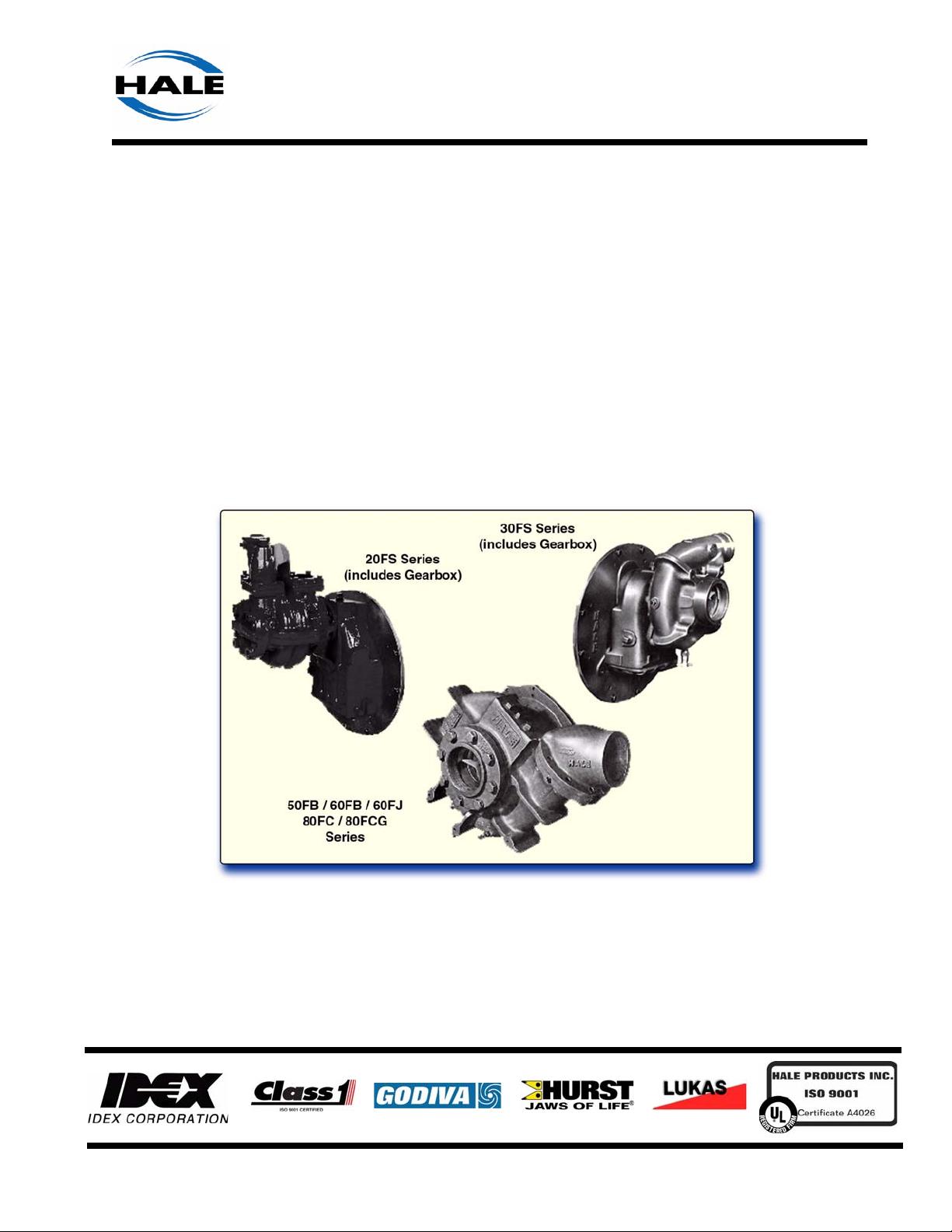
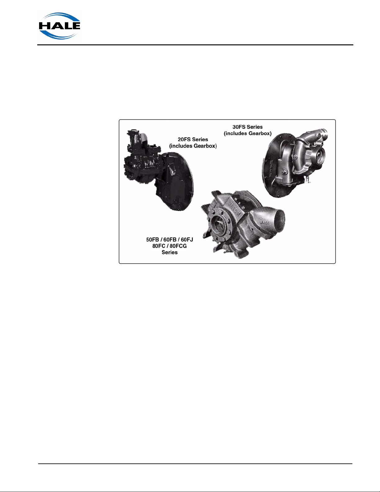
Figure 2-1: Typical Pump End Pumping Systems
The Hale Pump End Series Pumping Systems fulfill many types of in-service fire fighting applications. The pumps are available in configurations
providing a wide range of pressures and flows to suit most user requirements in a transportable unit. (See Figure 2-1: “Typical Pump End Pumping
Systems.”)
The Pump End series pumping systems are capable pumping water from
draft, relay or hydrant and can deliver discharge pressures up to approximately 800 PSI (55 BAR) and flow up to approximately 3,000 GPM (11,356
LPM / 189 LPS), NFPA 1901 performance rated. For a unit overview, see
heading, 2.2 “Pumping System Overview” beginning on page 22.
Pump end systems are available in the following models:
20FS-2M / 20FS-3M / 20FS-4M Series, with Gearbox
❑ Standard centrifugal pump and gearbox assembly with universal
mounting bracket designed to bolt directly to either SAE #4 or #5
engine flywheel bell housing and available for gasoline or diesel
engines.
Pump Ends
p/n: 029-0020-61-0
19

❑ Introduction
❑ Pump delivers discharge pressures up to 800 PSI (55 BAR) and flow
rates up to approximately 100 GPM (379 LPM / 6 LPS), NFPA 1901
performance rated.
❑ Suction — 2” (51 mm) female NPT flange
❑ Discharge — 1-1/2” (38 mm) female NPT
30FS2 / 30FS3 / 30FS4 Series, with Gearbox
❑ Standard centrifugal pump and gearbox assembly with universal
mounting bracket designed to bolt directly to either SAE #8 or #10
engine flywheel housing and available for gasoline or diesel engines.
❑ Pump delivers discharge pressures up to 300 PSI (21 BAR) and flow
rates up to approximately 400 GPM (1,514 LPM / 25 LPS), NFPA
1901 performance rated.
❑ Suction — 3” (76 mm) female NPT flange / 4” (102 mm) Victaulic
❑ Discharge — 2” (51 mm) female NPT / #115 flange
®
40FB / 50FB Series, Bell Housing or Pedestal Mount (-U-U
❑ Standard centrifugal pump end with universal mounting bracket
and -U-M Series)
designed to bolt directly to either SAE #10 or #11 engine flywheel
housing and available for gasoline or diesel engines.
❑ Pump delivers discharge pressures up to 250 PSI (17 BAR) and flow
rates up to approximately 800 (40FB) and 1,000 (50FB) GPM (3,028 3,785 LPM / 51 - 63 LPS), NFPA 1901 performance rated.
❑ Suction — 5” (127 mm) female NPT flange, optional
❑ Discharge — 4” (102 mm) female NPT flange, optional
FB50 / FB75 / FB100 Series, Bell Housing Mount
❑ Standard centrifugal pump end with universal mounting bracket
designed to bolt directly to either SAE #4 or #3 engine flywheel housing and available for gasoline or diesel engines.
❑ Pump delivers discharge pressures up to 350 PSI (24 BAR) and flow
rates up to approximately 500 (40FB) and 1,000 (50FB) GPM (1,893 3,785 LPM / 32 - 63 LPS), NFPA 1901 performance rated.
❑ Suction — 4-1/2”, 5” or 6” (114 mm, 127 mm or 152 mm)) male NS
thread
20
❑ Discharge — 2-1/2” (64 mm) female NS thread, or optional 3” (76 mm)
valve
❑ Blank Flange Option — 2-1/2”, 3” up to 5” (64 mm, 76 mm up to 127
mm). Consult Hale Products for additional information and various
tube lengths available.
Pump Ends
p/n: 029-0020-61-0

Introduction ❑
60FBG Series, with Gearbox
❑ Standard centrifugal pump and gearbox assembly with universal
mounting bracket designed to bolt directly to either SAE #2 or #3
engine flywheel housing and available for gasoline or diesel engines.
❑ Pump delivers discharge pressures up to 250 PSI (17 BAR) and flow
rates up to approximately 1,500 GPM (5,678 LPM / 95 LPS), NFPA
1901 performance rated.
❑ Suction — 6” (152 mm) female NPT flange, optional
❑ Discharge — 4” (102 mm) flange / 4” NPT check valve, optional
60FJ Series, Bell Housing Mount
❑ Standard centrifugal pump end with universal mounting bracket
designed to bolt directly to either SAE #10 or #11 engine flywheel
housing and splined shaft, available for gasoline or diesel engines.
❑ Pump delivers discharge pressures up to 250 PSI (17 BAR) and flow
rates up to approximately 1,200 GPM (4,543 LPM / 76 LPS), NFPA
1901 performance rated.
❑ Suction — 6” (152 mm) female NPT flange, optional
❑ Discharge — 4” (102 mm) flange / 4” NPT check valve, optional
80FC Series, Bell Housing Mount
❑ Standard centrifugal pump end with universal mounting bracket
designed to bolt directly to either SAE #11 or #4 engine flywheel housing and available for gasoline or diesel engines.
❑ Pump delivers discharge pressures up to 160 PSI (11 BAR) and flow
rates up to approximately 3,000 GPM (11,356 LPM / 189 LPS), NFPA
1901 performance rated.
❑ Suction — 8” (203 mm) female NPT flange, optional
❑ Discharge — 6” (152 mm) flange, optional
80FC (-G or -U) Series, with gearbox (-G) or pedestal (-U)
❑ Standard centrifugal pump and gearbox (or pedestal) assembly with
universal mounting bracket designed to bolt directly to either SAE #?
or #? engine flywheel housing and available for gasoline or diesel
engines.
❑ Pump delivers discharge pressures up to 250 PSI (17 BAR) and flow
rates up to approximately 3,000 GPM (11,356 LPM / 189 LPS), NFPA
1901 performance rated.
Pump Ends
p/n: 029-0020-61-0
❑ Suction — 8” (203 mm) female NPT flange, optional
❑ Discharge — 4” (152 mm) flange / 6” NPT check valve, optional
21

❑ Introduction
NOTICE !
PERFORMANCE OF PUMP END PUMPING SYSTEMS MEET OR EXCEED
NFPA 1921 REQUIREMENTS. FOR COMPLETE NFPA 1921 COMPLIANCE,
THE PUMPING UNITS MUST BE MARKED WITH SPECIFIC LABELS. CONSULT FACTORY IF THESE LABELS ARE REQUIRED.
2.2 PUMPING SYSTEM OVERVIEW
❑ Typical 20FS Series — see Figure 2-2: “Typical 20FS Series Pump Sys-
tem Overview” on page 23.
❑ Typical 30FS Series — see Figure 2-3: “Typical 30FS Series Pump Sys-
tem Overview” on page 24.
❑ Typical 40 / 50FB Series — see Figure 2-4: “Typical 40 / 50FB Series
Pump System Overview” on page 25.
❑ Typical FB50 / FB75 / FB100 Series — see Figure 2-5: “Typical FB50,
FB75 and FB100 Series Engine Mount Pump End Overview” on page
26.
❑ Typical 60FB / 60FJ Series — see Figure 2-6: “Typical 60FBG Series
Pump System Overview” on page 27.
❑ Typical 80FC / 80FCG Series — see Figure 2-7: “Typical 80FC Series
Pump System Overview” on page 28.
❑ Typical Check Valve Option, Discharge — see Figure 2-9: “Check
Valve Option, Discharge” on page 30.
22
Pump Ends
p/n: 029-0020-61-0
Introduction ❑
Pump Ends
p/n: 029-0020-61-0
Figure 2-2: Typical 20FS Series Pump System Overview
23

❑ Introduction
24
Figure 2-3: Typical 30FS Series Pump System Overview
Pump Ends
p/n: 029-0020-61-0
Introduction ❑
Pump Ends
p/n: 029-0020-61-0
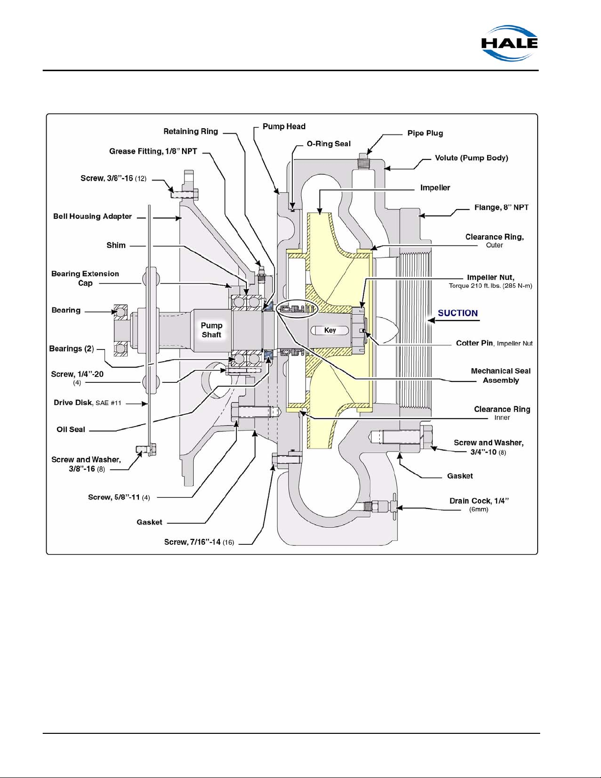
Figure 2-4: Typical 40 / 50FB Series Pump System Overview
25
❑ Introduction
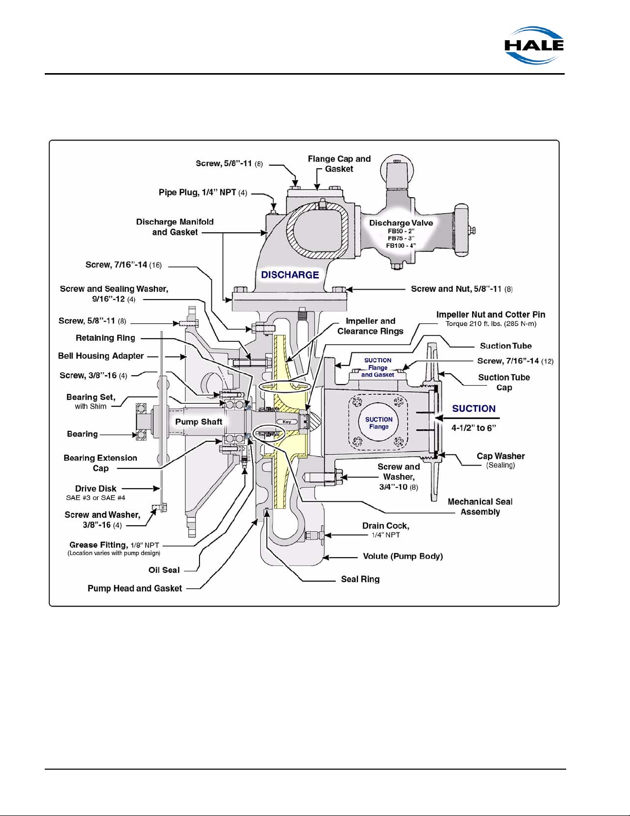
Figure 2-5: Typical FB50, FB75 and FB100 Series Engine Mount Pump End Overview
26
Pump Ends
p/n: 029-0020-61-0
Introduction ❑
Pump Ends
p/n: 029-0020-61-0
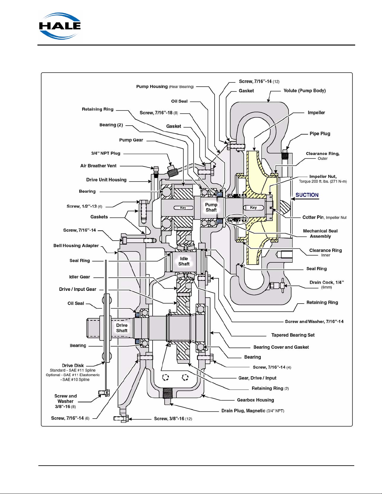
Figure 2-6: Typical 60FBG Series Pump System Overview
(Shown with G Series Gearbox)
27
❑ Introduction
28
Figure 2-7: Typical 80FC Series Pump System Overview
(Shown with Engine Mount Bell Housing)
Pump Ends
p/n: 029-0020-61-0
Introduction ❑
Pump Ends
p/n: 029-0020-61-0
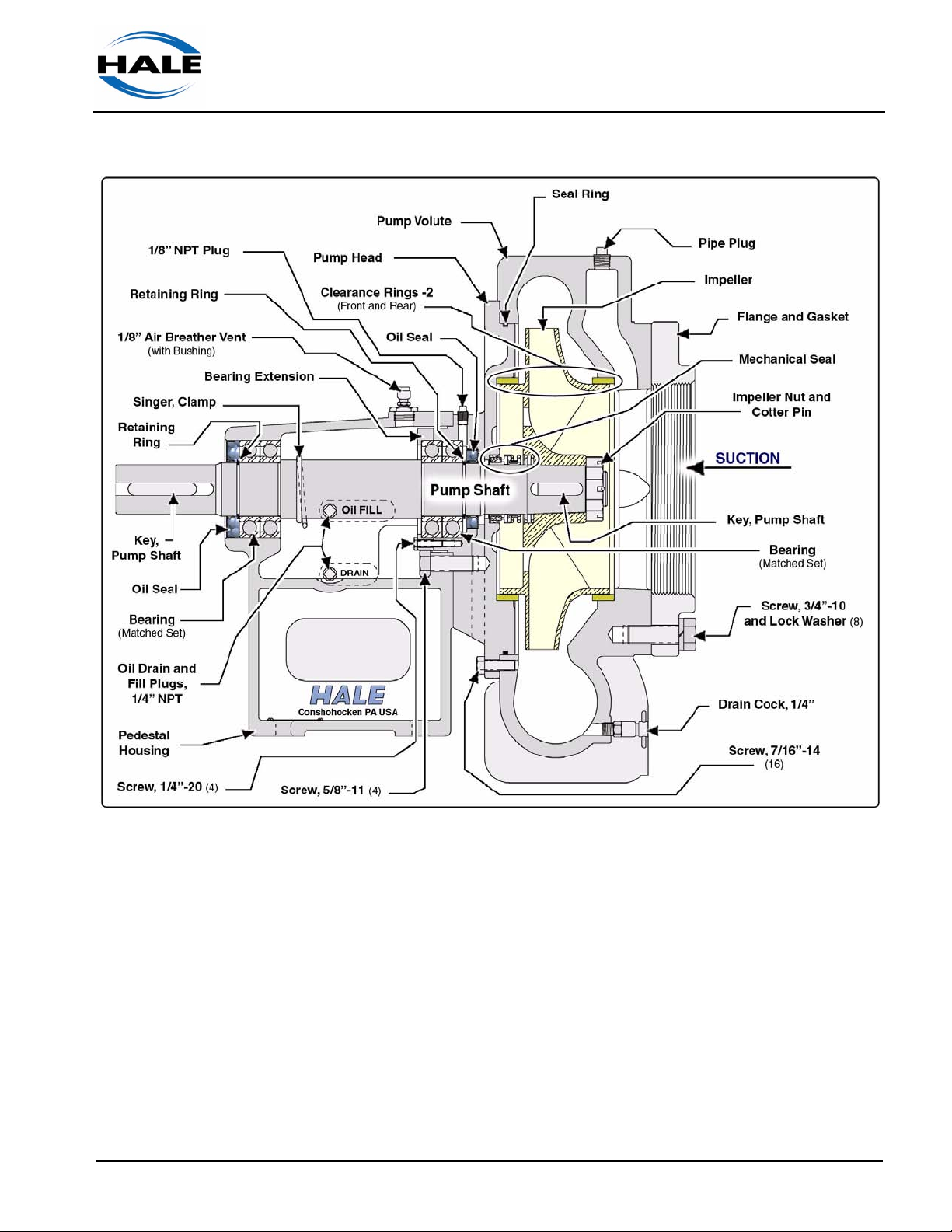
Figure 2-8: Typical 80FC-U Series Pedestal Pump System Overview
29
❑ Introduction
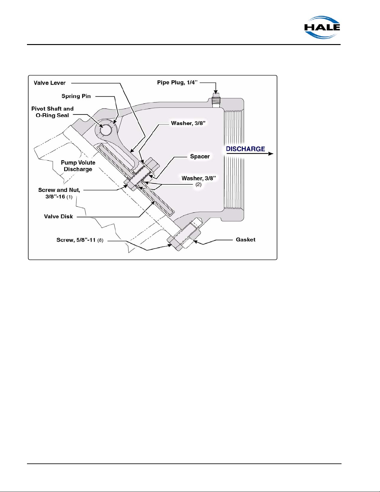
Figure 2-9: Check Valve Option, Discharge
(Size determined by pump discharge)
30
Pump Ends
p/n: 029-0020-61-0

2.3 PRINCIPLES OF OPERATION
Centrifugal Force
Hale pumps are centrifugal pumps that operate on the principle of centrifugal force created by a rapidly spinning disk. (See Figure 2-10: “Centrifugal
Force - Rotating Disk.”)
As the disk is rotated, it throws water from the center toward the outer circumference of the disk. The
velocity at which the water travels from the center
directly relates to the diameter of the disk and the
speed of rotation.
When water is confined in a closed container, such
as the volute (pump body), the velocity of the water
is converted to pressure that rises to a level dependent on the speed of rotation.
Introduction ❑
There are three interrelated factors that regulate
the performance of a centrifugal pump:
❑ SPEED (RPM) If the speed of rotation
Figure 2-10: Centrifugal
Force - Rotating Disk
increases with flow held constant, fluid pressure increases.
❑ PRESSURE If pressure changes with speed held constant, the flow,
measured in gallons or liters per minute (GPM/LPM), changes inversely;
if pressure increases, flow decreases. Pressure is usually measured in
pounds per square inch (PSI) or BAR.
❑ FLOW If the pressure is held constant, the flow increases with an
increase in the speed of rotation. Flow is measured in the number of gallons of fluid per minute (GPM or LPM) that a pump can deliver when supplied from draft.
A centrifugal pump is preferred by the fire protection service due to its ability
to fully utilize any positive suction inlet pressure, reducing the amount of
work done by the pump.
For example, if the required discharge pressure is 120 PSI (8.3 BAR), and
the inlet pressure is 45 PSI (3.1 BAR), the pump must only produce the difference in pressure or 75 PSI (5.2 BAR).
Pump Ends
p/n: 029-0020-61-0
This contributes to improved performance with reduced maintenance.
Decreased maintenance is aided by the fact a centrifugal pump has few
moving parts.
31

❑ Introduction
As the impeller rotates, the
water moving outward in the
impeller creates reduced pressure or a vacuum in the suction eye allowing atmospheric
pressure to push water into the
pump impeller, replacing the
water discharged. (See Figure
2-11: “Pump Water Flow, Cutwater.”)
During operation water enters
the suction eye of the impeller.
The rotating impeller vanes
develop discharge pressure
and via the “cutwater *,” directs
the water to the discharge
opening.
* The “cutwater” is a wedge that
divides the water between the volute
(pump body) and the pump discharge.
Figure 2-11: Pump Water Flow, Cutwater
2.4 PUMP COMPONENTS
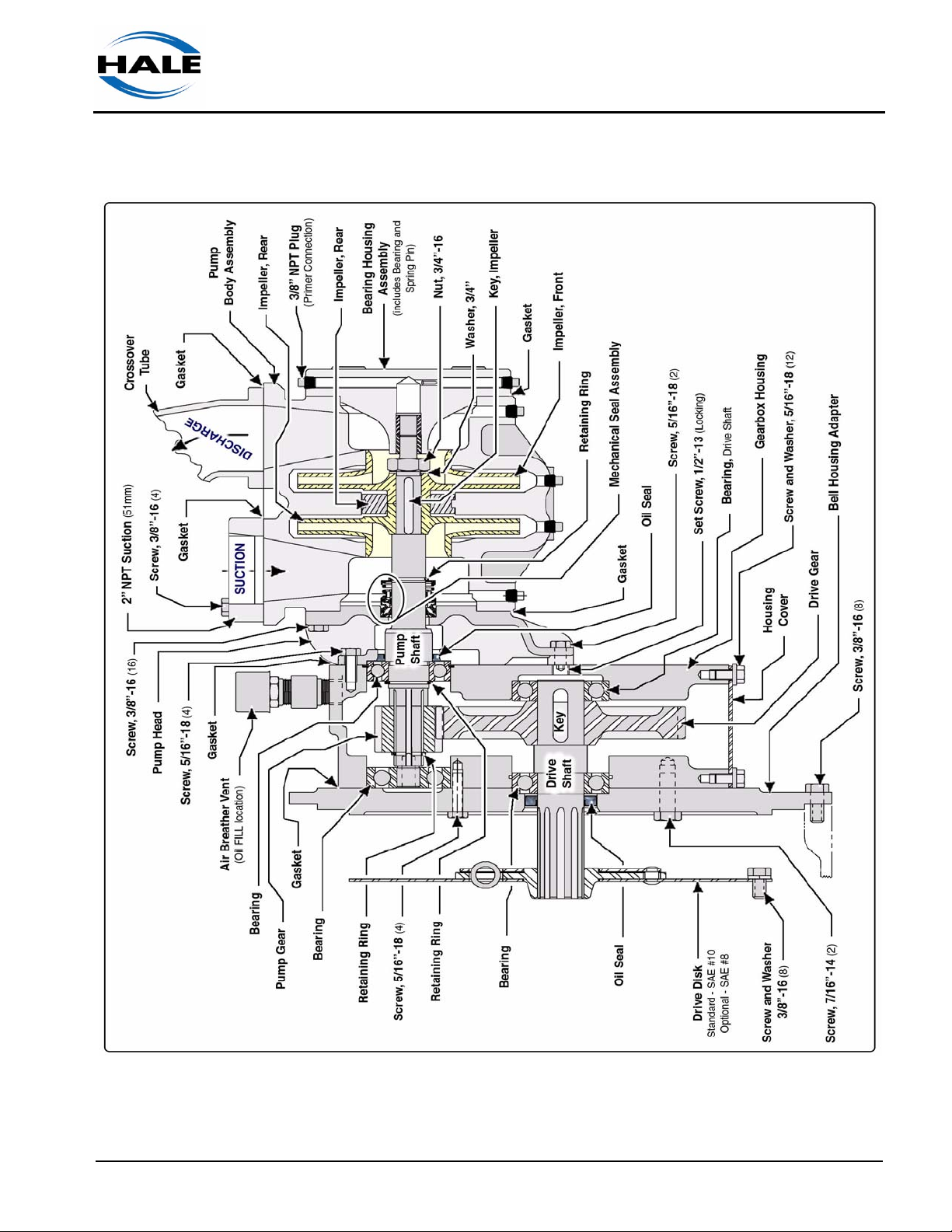
(See Figure 2-12: “Typical Pump and Gearbox Overview,” on page 33.)
The Hale single-stage pump consist of:
❑ Volute (Pump Body)
❑ Impeller and Clearance Ring
❑ Mechanical Seal
❑ Gearbox / Pedestal Option
Volute, Pump Body
(See Figure 2-12: “Typical Pump and Gearbox Overview,” on page 33.)
As water discharges from the impeller, it enters the volute (pump body).
The volute is constructed from fine-grain cast iron and shaped so that its
area increases from the cutwater to its full capacity at the volute throat.
32
Pump Ends
p/n: 029-0020-61-0

This gradual increase in
size maintains a constant average velocity
through the volute.
The volute is a single
piece, and must be
removed to service the
impeller, clearance rings,
and mechanical seal.
Removal of the volute
can often be accomplished without removing the pump and
gearbox assembly from
the apparatus.
Introduction ❑
Figure 2-12: Typical Pump and Gearbox Overview
Impeller
The impeller provides velocity to the water. Water enters the rotating impeller at the intake (or eye), and is confined by the shrouds and the vanes to
build pressure. The vanes guide water from the inlet to the discharge and
reduce the turbulence of the spinning water. (See Figure 2-13: “Impeller
Operation.”)
Pump Ends
p/n: 029-0020-61-0
Figure 2-13: Impeller Operation
As water discharges from the impeller, it enters the volute (pump body).
The volute increases in size from the cutwater to its full capacity at the
volute throat. This gradual increase maintains a constant average velocity
through the volute. Figure 2-13: “Impeller Operation” traces a drop of water
from the intake of the impeller to the discharge outlet.
33

❑ Introduction
Clearance Rings
Clearance rings prevent pressurized water that is leaving the pump volute
from returning to the intake of the impeller. Clearance rings at the impeller
intake also prevent leakage, accomplished by limiting the radial clearance
between the spinning impeller and the stationary clearance ring. Also see
Figure 2-12: “Typical Pump and Gearbox Overview” on page 33.
Typically, a clearance ring has a radial clearance of about 0.0075” (0.191
mm) or between 0.015” to 0.020” (0.381-0.508 mm) per side. However, due
to foreign material found in the water, this clearance increases over time
as the pump is operated. Clearance rings are designed for replacement
when wear limits cause the pump to exceed NFPA satisfactory
performance.
Mechanical Seal
The “maintenance-free,” mechanical seal is common to Hale pumps. (See
Figure 2-14: “Typical Mechanical Seal Overview,” on page 34.)
The stationary seat
is in constant contact with a rotating
seal ring to prevent
leakage. The sealing diaphragm is
made of a rubber
elastomer specifically designed for
high-temperature
operations.
Note: Mechanical
seals do not drip
like older pump
packing. A Hale
pump with a drip from the seal requires service.
Figure 2-14: Typical Mechanical Seal Overview
WARNING !
34
IF A PUMP IS OPERATED WITHOUT WATER FOR EXTENDED PERIODS, OR
WITHOUT DISCHARGING WATER, IT COULD OVERHEAT. THIS CAN DAMAGE THE MECHANICAL SEAL OR THE DRIVE MECHANISM.
Pump Ends
p/n: 029-0020-61-0

Ball Bearings
Ball bearings support and align the impeller and input shafts for smooth
operation. They are the most common anti-friction bearings used and offer
a major contribution to the life of a fire pump.
2.5 GEARBOX OPTION
Hale pumps can be equipped with an all ball bearing-type gearbox, utilizing
helical gears to reduce operating noise. To accommodate a wide range of
engines, this speed increasing gearbox is available in a variety of ratios.
Hale pumps also feature, as standard equipment, a gearbox cooling tube to
maintain proper operating temperatures.
Introduction ❑
2.6 PEDESTAL MOUNTING OPTION
Hale pump ends are also available with an all ball bearing-type pedestal
mount between the pump and the engine bell housing (flywheel) adapter.
(See Figure 2-15: “Pedestal Mount.”)
Pump Ends
p/n: 029-0020-61-0
Figure 2-15: Pedestal Mount
35

❑ Introduction
The pedestal is constructed of fine grain cast iron, and consists of bearings,
an oil seal and an oil reservoir.
2.7 HALE ENGINE MOUNT BELL HOUSING
Model pump ends are available with an adapter to accept #2, #3, #4 and #5
SAE bell housings. Elastomeric drive discs are also available for 10”
(254mm) and 11.5” (292mm) clutch discs.
(See Figure 2-16: “Bell Housing Mount,” on page 36.)
36
Figure 2-16: Bell Housing Mount
Pump Ends
p/n: 029-0020-61-0

2a Accessories / Options
The following accessories and /or options are available to complete a system installation:
❑ Anodes
❑ Auxiliary Cooling, standard on some equipment
❑ Pressure Control Devices (Relief Valves or Governors)
❑ Thermal Relief Valve (TRV)
❑ Priming Systems
❑ Torrent Stainless Steel SVS Valves
2A.1 ANODES
Accessories / Options ❑
The Hale Anode System helps prevent damage caused by galvanic corrosion in the pump. Galvanic corrosion occurs when different conducting
materials are connected electrically and exposed to fluid. This results in
corrosion of the less resistant of the two metals, while the more resistant
metal is protected. (See Figure 2a-1: “Hale 1-1/4” NPT Anode.”)
Hale offers two types of
anodes:
❑ Zinc anode - recommended
for pumps where corrosion
is an issue, including brackish or salt water exposure.
❑ Magnesium anode - avail-
able for use if the pump
already uses zinc anodes
and galvanic corrosion is
still a concern. Magnesium
anodes contain a notch in
the hex head for identifica-
Figure 2a-1: Hale 1-1/4” NPT Anode
tion.
Section 2a: Accessories
Hale Products, Inc., May 2006, Rev-B
The Anode kit is designed for installation in the standard Hale 115 series
flange opening. It is recommended that one anode be installed on each suction manifold and one on the discharge side. Performance varies with water
quality and PH.
37

❑ Accessories / Options
2A.2 AUXILIARY COOLING
Gearbox Manifold Coolers
Figure 2a-2: Typical Gearbox Manifold Coolers
For pumps not equipped with standard gearbox cooling, a cooler option is
available. (See Figure 2a-2: “Typical Gearbox Manifold Coolers.”)
The gearbox cooler circulates pump water to transfer heat from the gearbox
oil to the pump discharge, thus maintaining proper operating temperatures.
Heat Exchanger, “K” Series
The Hale Model “K” heat exchangers, meet NFPA 1901 requirements.
These units are used with any size radiator and use water from the pump to
help maintain the proper temperature of the engine coolant during pumping.
(See Figure 2a-3: “Model “K” Heat Exchanger,” on page 39.)
Note: A valve is normally added at the operator’s panel allowing the operator to
control the amount of water supplied to the Model “K” heat exchanger.
2A.3 PRESSURE AND RELIEF VALVE CONTROL
38
Note: For additional information about the pressure and relief valves in your system, see the separate manual provided with the valves. Also see Section 9,
“Drawing Package” on page 133.
Hale Products, Inc., May 2006, Rev-B
Section 2a: Accessories

Accessories / Options ❑
Figure 2a-3: Model “K” Heat Exchanger
P Series Relief Valve System
The P Series relief valve system is a
bronze, variable-pressure setting, relief
valve that prevents undue pressure per
the requirements of NFPA Standard
1901. An AMBER indicator light on the
operator control panel signals when the
valve is open. (See Figure 2a-4: “P
Series Relief Valve Control.”)
The P series relief valve system includes
a panel mounted control valve (PM) and
a relief valve (P25, P30 or P30V). Also
see Section 9, “Drawing Package” on
page 133.
Thermal Relief Valves (TRV)
Section 2a: Accessories
Hale Products, Inc., May 2006, Rev-B
Thermal Relief Valves (TRV) protect the
pump from overheating. (See Figure 2a5: “Thermal Relief Valve, TRV,” on page
40.)
Figure 2a-4: P Series Relief Valve
Control
39

❑ Accessories / Options
40
Figure 2a-5: Thermal Relief Valve, TRV
The valve monitors the water temperature in the pump. When temperatures
exceed 120° F (49° C), the valve automatically OPENS. When the temperature returns to a safe level, the valve CLOSES.
TRV-L Kit
The TRV-L kit includes a chrome panel placard with a warning light, a light
test button, and a pre-assembled wire harness. The RED light illuminates
when the TRV is open and discharging water. (See Figure 2a-5: “Thermal
Relief Valve, TRV.”) An optional buzzer, mounted on the operator panel,
provides an audible warning.
Hale Products, Inc., May 2006, Rev-B
Section 2a: Accessories

2A.4 PRIMING SYSTEMS
Hale recommends and uses Rotary Vane Positive Displacement ESP
pumps for priming. Priming pumps are used to evacuate air in the suction
hose and pump. (See Figure 2a-6: “Rotary Vane ESP Priming Pump.”)
Accessories / Options ❑
Figure 2a-6: Rotary Vane ESP Priming Pump
The Hale ESP series priming pump is an environmentally friendly primer
that does not require a separate lubricant reservoir. The vanes and pump
body are self-lubricating for maintenance free operation. An ESP priming
pump also uses a single control to open the priming valve and start the
priming motor. See separate manual, Hale p/n: 029-0810-01-0, for additional installation and operating instructions.
Priming Valves
Hale priming valves open when the priming pump is operated to allow the
air to escape from the pump. Two priming valves are offered:
❑ Hale Semi-Automatic Priming Valve (SPVR), for Remote Mounting
A single push button on the operator’s panel starts the priming pump
motor. When a vacuum is created, the SPVR OPENS. (See Figure 2a7: “SPVR Priming Valves,” on page 42.)
Releasing the push button stops the priming pump and the SPVR
CLOSES.
Section 2a: Accessories
Hale Products, Inc., May 2006, Rev-B
41

❑ Accessories / Options
Figure 2a-7: SPVR Priming Valves
❑ The Hale PVG Priming Valve
The PVG is a combination valve and switch and is mounted on the pump
operator’s panel. (See Figure 2a-8: “PVG Priming Valves.”)
Pulling the handle out OPENS the valve and energizes the primer motor.
Pushing the handle in de-energizes the motor and CLOSES the valve.
Figure 2a-8: PVG Priming Valves
2A.5 PUMP SHIFT, AUTOMATIC (VPS / KPS)
The Hale Automatic Pump Shift, Models VPS or KPS, is a remote, pneumatically operated, shifting device to shift the pump transmission from
ROAD-to-PUMP and back again. (See Figure 2a-9: “Automatic Pump Shift
Overview,” on page 43.)
42
Hale Products, Inc., May 2006, Rev-B
Section 2a: Accessories

Accessories / Options ❑
Figure 2a-9: Automatic Pump Shift Overview
It uses available apparatus vacuum or air pressure for power and is activated by an in-cab pump shift control valve. (See Figure 2a-10: “Pump Shift
Control Valve.”) The system includes a three-position pump shift control
valve assembly and indicator lights (GREEN), mounted in the operator’s
cab and on the operator’s panel.
Section 2a: Accessories
Hale Products, Inc., May 2006, Rev-B
Figure 2a-10: Pump Shift Control Valve
43

❑ Accessories / Options
2A.6 TORRENT SVS VALVES
Torrent SVS valves control the flow to and from the full range of Hale
pumps. SVS valves enable the operator to shut off flow completely, or throttle the flow rate from a trickle to full flow. (See Figure 2a-11: “Typical SVS
Valve Primary Components.”)
44
Figure 2a-11: Typical SVS Valve Primary Components
Numerous adapters tailor the valve to almost any installation requirement.
See separate manual (Hale p/n: 029-0020-90-0) provided for detailed operating and service instructions.
Hale Products, Inc., May 2006, Rev-B
Section 2a: Accessories

3 Basic Operation
THE PROCEDURES IN THIS SECTION ARE GENERAL OPERATING PROCEDURES. NOT ALL PROCEDURES IN THIS SECTION MAY APPLY TO YOUR SPECIFIC OPERATIONAL REQUIREMENTS. REFER TO ONLY THOSE SECTIONS
WHICH APPLY TO YOUR OPERATIONAL REQUIREMENTS.
THESE PROCEDURES DO NOT REPLACE THE PROCEDURES, POLICIES OR
GUIDELINES ESTABLISHED BY THE AUTHORITY HAVING JURISDICTION.
ALWAYS REFER TO THE PROCEDURES PROVIDED BY THE AUTHORITY HAVING JURISDICTION FOR OPERATING PROCEDURES, SETTING WHEEL
CHOCKS, AS WELL AS LAYOUT AND CONNECTION OF HOSES, VALVES AND
DRAIN COCKS. ALL VALVES, DRAIN COCKS AND CAPS SHOULD BE CLOSED.
Operation ❑
WARNING !
THOROUGHLY REVIEW THE ENGINE OPERATING PROCEDURES PROVIDED IN
THE ENGINE MANUFACTURER’S MANUAL, PROVIDED WITH THE SYSTEM.
3.1 OVERVIEW
❑ Fluid Levels - on page 45.
❑ Preparing to tow - on page 46.
❑ Pumping Operations - on page 46.
❑ Relief Valve Procedures - on page 50.
❑ Post-Operation Procedures - on page 51.
Note: Also refer to NFPA 1901 Regulations for additional information for skid and
trailer requirements.
3.2 FLUID LEVELS
To meet various shipping regulations, ALL fluids within the engine, battery (if
applicable) and pump, gearbox and pedestal assemblies are drained prior to
shipping from the factory.
Pump Ends
p/n: 029-0020-61-0
45

❑ Operation
IMPORTANT !
AT INSTALLATION AND BEFORE OPERATION, ALL FLUIDS MUST BE ADDED PER
THE MANUFACTURER’S REQUIREMENTS AND TO THE APPROPRIATE LEVELS.
SEE SEPARATE DOCUMENTATION PROVIDED WITH THE ENGINE AND PUMP
END ASSEMBLIES FOR PROPER FLUIDS TO USE AND QUANTITIES REQUIRED.
Before operation, refill -
❑ Engine crankcase OIL.
❑ Engine WATER coolant (anti-freeze).
❑ Engine battery fluid (ELECTROLYTE).
❑ Pump, gearbox and pedestal OIL.
3.3 PREPARING TO TOW
If your system is trailer mounted, the trailer includes an identification and information tag which contains essential information for safe use of your trailer. The
tag is generally located in the tongue area or front cross member of the trailer.
It includes the vehicle identification number (VIN), the maximum gross weight
that each axle can support (GAWR) and the maximum allowable gross weight
of the trailer and its contents (GVWR).
IMPORTANT !
FOR ADDITIONAL TOWING PREPARATION INFORMATION, SEE YOUR SKID AND
TRAILER MANUAL PROVIDED. ALSO SEE THE TRAILER OPERATIONS MANUAL
PROVIDED SEPARATELY WITH YOUR SYSTEM.
3.4 PUMPING OPERATIONS
Initial Start Up
Prior to operating the unit, check for proper:
46
❑ Engine FUEL level.
❑ Engine OIL level.
❑ Engine COOLANT level.
Pump Ends
p/n: 029-0020-61-0

Operation ❑
❑ Engine battery ELECTROLYTE level
(not required for live sealed high performance-type batteries).
❑ Pump, gearbox and pedestal OIL level, if supplied.
Pumping Operations
1. Position the skid or trailer as close to the water source as practical. Pumps
smaller than 1,500 GPM (5,678 LPM) can draw 100% of rated capacity with
less than 10 feet (3.05 meters) vertical lift and 20 feet (6 meters) of suction
hose. Pumps smaller than 3,000 GPM (11,356 LPM) have six (6) feet (1.8
meter) vertical lift capability.
As the vertical lift increases, pump capacity is reduced. (See Figure F-3:
“Lift Loss from Elevation” on page 147.) Also see heading “Draft Operation
Limiting Factors” on page 49.
2. For trailers, apply the brakes, chock the wheels and lower the trailer jacking
stabilizers to level and support the trailer. See WARNING ! note on page
45.
3. Attach a suction line to the
pump, installing a strainer
on the opposite end. Submerge the strainer in the
water at least four (4)
times the pipe diameter
below the water level.
Make sure the suction line
connection is tight. (See
Figure 3-1: “Typical Portable Pump Installation.”)
Keep the strainer OFF the
Figure 3-1: Typical Portable Pump Installation
bottom of the water
source and away from sand, leaves or other foreign matter which could
block or restrict flow.
4. Remove engine compartment side panels, if so equipped.
Pump Ends
p/n: 029-0020-61-0
5. Check engine cooling system for sufficient coolant.
6. Start the engine. See engine manufacturer’s manual for start-up and operation procedures.
7. Check that all drain valves / cocks are fully CLOSED.
47

❑ Operation
8. Activate the priming pump - pull the control handle, or press the pushbutton.
Your departmental manual for pumping should specify the correct RPM for
priming. However, in general, priming should be operated at IDLE.
Running the engine at speeds higher than 1,200 RPM during priming is not
recommended. It does not improve the priming operation but can cause
damage to the pump.
CAUTION !
IF THE DISCHARGE GAUGE READING DOES NOT INCREASE, THE INTAKE
GAUGE READING DOES NOT FALL BELOW ZERO (0), OR THE PRIMING PUMP
DOES NOT DISCHARGE WATER TO THE GROUND WITHIN 30 TO 45 SECONDS,
DO NOT CONTINUE TO RUN THE PRIMING PUMP.
STOP THE PUMP AND CHECK FOR AIR LEAKS OR POSSIBLE PROBLEMS. SEE
SECTION 5 “TROUBLESHOOTING,” ON PAGE 71.
9. When operating from a positive pressure source (e.g. hydrant or relay),
make sure any air is purged from the hose and pump.
CAUTION !
WHEN OPERATING FROM A POSITIVE PRESSURE SOURCE WITH A SOFT SUPPLY HOSE, DO NOT DRAW RESIDUAL PRESSURE BELOW 5 PSI (0.4 BAR) OR
YOUR DEPARTMENTAL LIMITS. DAMAGE TO THE HYDRANT, HOSE AND POSSIBLY THE PUMP MAY RESULT.
10. Monitor the intake and discharge master gauges. When the pump is
primed, the intake reading falls below zero (0), and the discharge pressure
starts to increase. You may also hear water splashing on the ground, indicating the pump is primed.
11. Gradually open the discharge valve until water emerges in a steady stream.
Then open the other discharge valves to the desired setting.
12. Gradually open the engine throttle until the desired pressure or flow is
achieved.
48
As the throttle is opened, the pressure gauge reading increases with the
engine speed. If the engine speed increases without an increase in pressure, the pump may be cavitating.
Pump Ends
p/n: 029-0020-61-0

Operation ❑
CAUTION !
DO NOT CAUSE A WHIRLPOOL AT THE STRAINER. THIS ALLOWS AIR INTO THE
PUMP, CAUSING ROUGH OPERATION AND PULSATION. REPOSITION THE
STRAINER OR REDUCE FLOW.
13. If the pump is cavitating, warn personnel that the flow is being REDUCED.
Close the throttle and / or discharges slowly until you operate without
cavitation. The following can also lead to cavitation:
❑ Large nozzle tips - use smaller nozzle to reduce flow.
❑ Air enters with the water - Air leaks can cause rough operation and an
increase in engine speed without an increase in pressure or flow.
If an air leak is suspected, discontinue pumping - see heading “Troubleshooting” on page 71.
❑ Hot water - see Figure F-2: “Lift Loss from Temperature” on page 147.
❑ Low barometer - see Figure F-3a: “Lift Loss from Barometric Reading”
on page 147.
❑ High lift - see Figure F-3: “Lift Loss from Elevation” on page 147.
Note: Also see Section “Appendix F: Cavitation” on page 145.
14. If a pump shutdown is desired while pumping from draft, reduce the engine
speed to IDLE and close the discharge valves.
To resume pumping, open the throttle and discharge valves. If the pump
overheats from continued churning without water flow, open the discharge
valves periodically to release hot water.
15. Set the automatic relief valve according to your fire department policy.
16. To avoid pump overheating, if not equipped with the Hale TRV valve, open
the pump auxiliary cooling system valve, or slightly open a discharge valve.
17. After completion of pumping procedures, gradually reduce the engine RPM
to IDLE speed and close discharge valves. Also see heading “Post Operation Procedures” on page 51.
Pump Ends
p/n: 029-0020-61-0
Draft Operation Limiting Factors
The effect of raised water temperatures when pumping from a positive pressure
source (i.e., a hydrant) is negligible on fire pump performance. However, when
pumping from draft (static source such as a pond, lake or basin), elevated water
temperature does have a limiting effect.
49

❑ Operation
Water temperatures above 95°F (35°C) cause a noticeable decrease in lift
when drafting. Also see Figure F-2: “Lift Loss from Temperature” on page 147.
Barometric pressures below 29” Hg. can also limit lift when drafting. High elevations and storm conditions can affect maximum flow available from any pump.
Also see Figure F-3a: “Lift Loss from Barometric Reading” on page 147.
3.5 RELIEF VALVE PROCEDURES
Be sure to select the correct procedure based on how the skid or trailer is
equipped. (See Figure 3-2: “TPM / PMD Relief Valve Control” on page 51.)
Some engines may utilize a governor in place of the relief valve.
Standard Relief Valve Procedures
1. Increase the engine RPM to the desired pump operating pressure while
reading the discharge pressure gauge.
2. Turn the handwheel slowly counterclockwise until the relief valve opens.
The pilot light illuminates and the master pressure gauge drops a few PSI
(BAR).
3. Turn the handwheel slowly clockwise until the master pressure gauge rises
to the desired pressure and the pilot light goes out.
4. When the pump is not in operation, turn the handwheel clockwise to a position slightly above the normal operating pressure. When the pump is put
into operation again, reset the valve to the desired operating pressure.
More complete and detailed information is found in the relief valve manual.
TPM Relief Valve Procedures
1. Set the pressure indicator on the PMD control valve to a position slightly
above the normal operating pressure (even before water starts to flow).
(See Figure 3-2: “TPM / PMD Relief Valve Control” on page 51.)
2. When normal operating pressure is achieved (as indicated on the master
pressure gauge while the pump is discharging water), slowly move the
adjusting handwheel counterclockwise until the relief valve opens.
3. The AMBER indicator light illuminates.
50
Pump Ends
p/n: 029-0020-61-0

4. Turn the handwheel slowly clockwise until the
light goes out.
5. When the pump is not in operation, turn the
handwheel clockwise to a position slightly
above the normal operating pressure. More
complete and detailed information is found in
the relief valve manual.
CAUTION !
THE PRESSURE INDICATOR ON THE PANEL IS
ONLY A ROUGH INDICATION OF TPM SETTING.
ALWAYS USE THE PRECEDING PROCEDURE TO
PROPERLY SET THE TPM RELIEF VALVE SYSTEM.
Operation ❑
Figure 3-2: TPM / PMD Relief
Val ve C o nt r o l
3.6 POST OPERATION PROCEDURES
1. Return the engine to IDLE, then slowly close all valves.
2. Drain the pump (especially important in freezing weather):
❑ Open the discharge valves, remove suction tube caps, and discharge
valve caps.
❑ Open the pump body drain cocks or Hale multiple drain valve. If a multiple
drain valve is used, all pump drain lines should be connected to this valve.
3. If sea water, dirty water, alkaline water or foam solution has been used,
FLUSH THE PUMP WITH CLEAN WATER.
4. If installed, drain the gearbox cooler. After the pump is completely drained,
replace all caps and close all valves.
5. For trailers, remove the wheel chocks only when preparing to leave the
scene.
6. Check engine oil, coolant and fuel levels and add proper type as needed.
Pump Ends
p/n: 029-0020-61-0
51

❑ Operation
7. Fill out the Pump Run Log, indicating total pumping and out-of-station time.
8. Report all pump, engine and equipment malfunctions, and irregularities to
the proper authority.
9. Know and follow all local procedures. See WARNING ! note on page 45.
52
Pump Ends
p/n: 029-0020-61-0

4 Preventive Maintenance
4.1 OVERVIEW
Hale Pump End Systems require minimal care and maintenance. Preventive
maintenance tasks take little time to perform and consist primarily of leak testing, lubrication and cleaning.
The following procedures are for normal use and conditions. Extreme conditions may indicate a need for increased maintenance. The procedures in this
section identify some extreme conditions and the additional measures needed
to ensure lengthened pump life and continuing dependability. Always follow
local maintenance and test procedures.
Preventive Maintenance ❑
WARNING !
BEFORE PERFORMING ANY MAINTENANCE ROUTINE, COMPLETELY REVIEW
THE SAFETY SECTION OF THIS MANUAL, BEGINNING ON PAGE 11.
ALSO REVIEW THE ENGINE MANUFACTURER’S MANUAL / OWNERS MANUAL
FOR ENGINE MAINTENANCE PROCEDURES.
TO PREVENT ACCIDENTAL STARTING, BEFORE SERVICING THE ENGINE OR
PUMP, ALWAYS DISCONNECT THE NEGATIVE (—) WIRE (BLACK) FROM THE
BATTERY TERMINAL.
Preventive / General Maintenance
Engine
For engine related preventive maintenance procedures, see the separate
engine manufacturer’s Operation and Maintenance Manual / Owners Manual
provided with each system.
Items to check:
Pump Ends
p/n: 029-0020-61-0
❑ Engine starting / stopping procedures
❑ Checking, adding and changing oil
❑ Changing oil and air filters
❑ Spark plug, check and/or replacement
53

❑ Preventive Maintenance
❑ Spark arrestor screen — clean or replacement
❑ Fuel requirements and adding fuel
If required, separate Engine Service Repair Manuals are available from the
engine manufacturer by contacting the engine manufacturer directly.
All engine related service and parts requests should first be directed to
the engine manufacturer. If additional information is needed, contact Hale
Customer Service at telephone number: 610-825-6300.
Skid and/or Trailer
See the Hale Skid and Trailer Service Maintenance manual, supplied with your
unit, for preventive and general maintenance requirements, intervals and
schedules.
Also see the trailer manufacturer’s documentation, supplied with your unit, for
preventive and general maintenance requirements, intervals and schedules for
the trailer assembly, axle, brake system, tires, etc.
Pump, Gearbox and Pedestal
Pump end, gearbox and pedestal preventive and general maintenance requirements, intervals and schedules are discussed in this manual.
Accessories
Various Hale accessories / options may be included with your unit, e.g., SVS
valves, P30 or P35 valves, TPM, etc. Refer to the appropriate Hale documentation, supplied with your unit, for maintenance requirements.
4.2 POST-OPERATION
1. Inspect the suction hose rubber washers and washers in the suction tube
caps. Remove foreign matter from under these washers. Replace worn,
damaged, or dry washers.
2. Verify that all discharge valves, booster line valves, drain valves, and cocks
are closed.
3. Tighten suction caps.
4. Make sure the gearbox oil reservoir is full to correct level - see heading “To
Check / Add Oil” on page 56.
54
Pump Ends
p/n: 029-0020-61-0

Preventive Maintenance ❑
5. Make sure the pedestal oil reservoir is full to correct level - see heading “To
Check / Add Oil” on page 57.
Also ensure that the engine has the proper amount oil and coolant. See
separate engine operation and maintenance manual provided.
4.3 EXTREME CONDITIONS
Extreme conditions occur when the pump has been operated during freezing
weather or when pumping from a water source that contains material that is
harmful to the pump if not purged.
During Freezing Weather
In freezing weather, drain the pump as follows:
1. Open all discharge and suction valves, remove suction tube caps and discharge valve caps.
2. Open pump body drain cocks and/or Hale multiple drain valve.
3. After the pump is completely drained, replace all caps and close all valves.
Pumping from Salt Water, Contaminated Water, or with Foam Solution
Thoroughly flush the pump and suction hoses using fresh water from a hydrant
or other clean water source.
After pumping foam, flush as above until all residue of foam is flushed from the
system.
4.4 WEEKLY
Weekly maintenance consists of the following
❑ Gearbox option, check / add oil - see page 56
❑ Pedestal option, check / add oil - see page 57
Pump Ends
p/n: 029-0020-61-0
❑ Check / add engine fluids - see page 58
❑ Relief valve testing - see page 58
❑ Governor testing - see page 59
55

❑ Preventive Maintenance
❑ Test the priming system - see page 59.
Establish and HOLD prime control for about three (3) to five (5) seconds to
flush fresh water through the priming pump.
Note: DO NOT apply lubricant the primer pump vanes or vane slots. Lubricant and
cold water produces a gummy residue that renders the unit defective.
❑ Perform valve maintenance - see page 59
❑ Check and clean the intake strainers - see page 60
❑ Verify all gauges are in working order - see page 60
❑ Operate pump controls - see page 60
If testing criteria is not met, refer to Section 5 “Troubleshooting” on page 71 for
corrective maintenance procedures.
Gearbox Option
Incorrect oil types or amounts of oil result in unnecessary high oil temperature
and possible wear or damage. Change the oil every 12 months, depending on
pump usage. All lubricants must meet service rating API GL-5 requirements.
Also see “Appendix C1: Lube and Sealant Specifications” on page 139. Also
review the appropriate pump installation and parts identification drawing —
heading “Drawing Package” on page 151.
To meet various shipping regulations, oil is drained from the gearbox (or pedestal) reservoir prior to shipping from the factory. At installation and before operating the first time, oil must be added to the appropriate level.
Note: Hale recommends using an SAE EP-90, 80W90 Lubricant or “RoadRanger”
Full Synthetic 75W-140 Transmission Lubricant, manufactured by the Eaton
ration, or equivalent.
To Check / Add Oil
1. Remove the gearbox oil LEVEL / FILL plug, and check the level of the oil in
the gearbox. (See Figure 4-1: “Typical Drain, Fill and Level Plugs” on page
57.) Have clean disposable shop rags and oil dry handy and a suitable container to collect any fluid.
®
Corpo-
see
Note: Assembly orientation determines which plugs are used for oil fill, drain and
level detection. For additional information, check the appropriate installation and
parts identification drawing — see heading “Drawing Package” on page 151.
2. The oil level should be up to the bottom of the oil DRAIN port hole.
56
Pump Ends
p/n: 029-0020-61-0

Preventive Maintenance ❑
Figure 4-1: Typical Drain, Fill and Level Plugs
3. If the oil appears white or “milky,” a water leak is indicated. Remove the
drain plug and drain the oil into a suitable container. Examine the oil for
metal flakes or other contamination.
Note: If water leak / contamination is suspected, see heading “Troubleshooting” on
page 49.
4. Either of these conditions indicates maintenance is required on the unit.
See Section 6 “Repair” on page 77.
Pedestal Option
For pedestal reservoir capacity review the appropriate pump installation and
parts identification drawing —
To Check / Add Oil
1. Remove the oil FILL plug, and check the level of the oil in the reservoir.
(See Figure 4-2: “Typical Pedestal Oil Servicing” on page 58.)
see heading “Drawing Package” on page 151.
Pump Ends
p/n: 029-0020-61-0
57

❑ Preventive Maintenance
Have clean disposable shop
rags and oil dry handy and a
suitable container to collect
the fluid.
2. If the oil appears white or
“milky,” a water leak is indicated.
Remove the DRAIN plug and
drain the oil into a suitable
container. Examine the oil for
metal flakes or other contamination.
Note: If water leak / contamination
is suspected, see heading “Troubleshooting” on page 49.
Figure 4-2: Typical Pedestal Oil Servicing
3. Add fresh oil through the oil FILL port until oil reaches the bottom of the hole
(just begins sweeping out of the hole). DO NOT OVERFILL. (See Figure 42: “Typical Pedestal Oil Servicing.”) Pedestal reservoir holds approximately
three (3) pints (1.4 liters) of approved SAE EP90 oil or equivalent.
4. Replace the oil FILL plug securely, using suitable thread sealant, and run
the pump for a short period, then recheck the oil level.
Check / Add Engine Fluids
To meet various shipping regulations, oil and water / antifreeze are drained from
the engine crankcase and radiator prior to shipping from the factory. The battery is also drained. At installation and before operating the first time, oil, water
/ antifreeze, etc. must be added to the appropriate levels.
Refer to the engine manufacturer’s operation and maintenance manuals provided with this system for FILL procedures, fluid capacities and types.
Relief Valve Test
When the relief valve is not in operation, keep the hand wheel set above the
normal operating pressure. (See Figure 3-2: “TPM / PMD Relief Valve Control”
on page 51.)
1. Prepare to pump from the onboard water tank, having the discharge flow
directed back to the water tank.
58
Pump Ends
p/n: 029-0020-61-0

Preventive Maintenance ❑
2. Increase the pump pressure up to normal operating pressure as indicated
on the master pressure gauge per normal operating procedures.
3. Turn the relief valve hand wheel counterclockwise until the valve opens.
The relief valve is open when the AMBER indicator light is ON and the pressure begins to drop. (See Figure 3-2: “TPM / PMD Relief Valve Control” on
page 51.)
4. Turn the relief valve hand wheel clockwise. The pressure should return.
Cycle the relief valve a few times to ensure that the hand wheel turns freely.
Observe the pressure gauge and indicator light for proper valve operation.
5. Return the relief valve hand wheel and the apparatus to normal operational
condition.
Governor Test
If your system is equipped with an electronic governor, follow the manufacturer’s instructions for preventive maintenance.
Priming System
1. Tighten all pump caps, and close all pump valves.
2. Pull the primer control while you watch for a below-zero (0) reading on the
master intake gauge.
3. Continue operation for three (3) to five (5) seconds after the primer starts
flushing water through the pump to clear any possible dirt or slug (gum)
buildup.
4. Verify that the master intake gauge readings hold for approximately five (5)
minutes after you release the primer control. A drop of 10” Hg. in this 5
minute period is anticipated per NFPA 1901.
5. If air leaks are heard or the gauge bounces back to or above zero (0), the
pump or valves require service.
Pump Ends
p/n: 029-0020-61-0
Valve Maintenance
Properly functioning valves are integral to the operation of the pump. Refer to
the separate valve manual for proper valve maintenance procedures.
59

❑ Preventive Maintenance
For example, lubricate all moving parts of the suction, discharge, hose drain,
and multi drain valves and valve linkage with a good grade, lithium base grease.
Note: The PMD valve should be lubricated every six (6) months.
Verify All Gauges are in Working Order
Any gauge that is repeated in another panel, must agree with the gauge on the
operator's panel. Gauges not reading within 10% of the calibrated test gauge
must be removed from service and re-calibrated.
Intake Strainers
❑ Check and clean any debris from the intake.
❑ Flush the pump, if required, using departmental/company procedures.
❑ Repair or replace any damaged strainers.
Inspect Water and Foam Tanks
Visually inspect water and foam tanks for proper level and gauge readings. If
any debris is present, flush the tanks to protect the pump from wear caused by
dirty water or foam concentrate.
Operate Pump Controls
Operate the pump drive controls to verify the pump engages. Verify the indicator lights work properly.
4.5 MONTHLY
Monthly maintenance includes the weekly maintenance procedures plus:
60
❑ Valve lubrication - see page 59
❑ Gearbox or pedestal option lubrication - see page 61
❑ Checking the pump and drive line bolts - see page 61
❑ Dry vacuum testing - see page 61
Pump Ends
p/n: 029-0020-61-0

Preventive Maintenance ❑
Valve Lubrication
1. On handwheel-type valves, including PM, PMD, and Transfer Valve Controls, if necessary, first remove old grease and paint, use a dry lubricating
spray on gears.
2. Lubricate suction threads with a light coat of grease.
Check Gearbox or Pedestal Lubrication
❑ To check the gearbox, see heading “Gearbox Option” on page 56.
❑ To check the pedestal reservoir, see heading “Pedestal Option” on page 57.
Pump and Flange Bolts
Check all pump and flange (bell housing) bolts to ensure:
❑ No bolts are missing.
❑ All bolts are tight. Use a torque wrench and torque bolts to the manufac-
turer's recommended specifications.
❑ Bolts used are “Grade 5” strength minimum for mounting and “Grade 8”
strength minimum for the driveline.
Priming System Test (Dry Vacuum Test)
(Refer to NFPA 1901 or NFPA 1911)
1. Close all valves and drains. Cap all suction openings and the outlet of the suction side relief valve (if
equipped).
2. Connect a test vacuum gauge or manometer to the
intake test gauge connection on the pump panel.
3. Engage the priming pump until the gauge indicates
at least 22” Hg vacuum. (See Figure 4-3: “PVG
Priming Valve Handle.”)
Figure 4-3: PVG Prim-
ing Valve Handle
Pump Ends
p/n: 029-0020-61-0
4. Compare the readings of the test gauge and the apparatus gauge. Note
any difference.
61

❑ Preventive Maintenance
5. STOP the priming pump and observe the gauge. If the vacuum falls more
than 10” Hg. in 5 minutes, it is an indication of at least one air leak.
Vacuum leaks can often be detected by ear if the apparatus engine is
turned OFF. Correct leaks immediately before returning the pump to service.
6. Test the suction hose as follows:
❑ Attach the suction hose to the pump.
❑ Place a suction tube cap on the end of the hose in place of a strainer.
❑ Close all valves and drains. Cap all suction openings and the outlet of the
suction side relief valve (if so equipped).
❑ Connect a calibrated vacuum gauge or manometer to the intake test
gauge connection on the pump panel.
❑ Engage the priming pump until the gauge indicates at least 22” Hg vac-
uum.
❑ Watch the gauge. If the vacuum falls more than 10”Hg. in 5 minutes, it
indicates at least one air leak.
❑ Verify the test gauge and the apparatus gauge display the same readings.
Repair or replace any gauges that do not display the correct pressure.
IF LEAKS CANNOT BE DETECTED BY FOLLOWING THE PROCEDURE, IT IS
ADVISABLE TO TEST THE PUMP HYDROSTATICALLY. TO TEST:
❑ OPEN ALL VALVES
❑ PLACE CAPS ON ALL VALVES
❑ CONNECT A POSITIVE PRESSURE SOURCE
❑ INSPECT THE PUMP FOR LEAKS
4.6 ANNUALLY
Annual maintenance consists of post-operation, weekly, and monthly maintenance, plus the following tasks:
IMPORTANT !
62
❑ Pump head bearing lubrication - see page 63.
❑ Replacing the pump gearbox oil - see page 63.
❑ Replacing the pump pedestal oil - see page 64.
Pump Ends
p/n: 029-0020-61-0

Preventive Maintenance ❑
❑ Relief valve system, check and repair - see page 65.
❑ Checking individual drain lines from the pump to the multi-drain to ensure
proper drainage and protection from freezing - see page 65.
❑ Test tank-to-pump flow rate - see page 67.
❑ Disassembly of priming pump to clean vanes - - see page 66. (Also see sep-
arate manual provided.)
IMPORTANT !
DO NO USE A LUBRICANT ON THE PUMP VANES AND VANE SLOTS. LUBRICANT AND COLD WATER FORM AN EVENTUAL GUMMY RESIDUE THAT RENDERS THE PRIMING SYSTEM INOPERATIVE. A COMPLETE AND THOROUGH
DISASSEMBLY AND CLEANING IS THEN REQUIRED.
❑ Run a yearly pump test to check performance levels - see page 66. (Also
see NFPA 1911 standard for more details.)
Pump Head Bearing Lubrication
❑ Every six (6) twelve
(12) months maximum, the pump head
bearings require fresh
lubrication, via the
grease fitting. (See
Figure 4-4: “Pump
Head Bearing Lubrication.”)
❑ Use a Lithium-based
grease with 1% to 3%
Molybdenum Disulfate. For a listing, see
“Appendix C1: Lube
and Sealant Specifications” on page 139.
Figure 4-4: Pump Head Bearing Lubrication
Change Gearbox Oil
Pump Ends
p/n: 029-0020-61-0
1. Place the pumping unit on a level surface allowing access to the gearbox
housing oil plugs. (See Figure 4-1: “Typical Drain, Fill and Level Plugs” on
page 57.)
63

❑ Preventive Maintenance
2. Remove the Oil FILL and DRAIN (magnetic) plug and drain the gearbox oil
into a suitable container. For container size based on gearbox capacity, see
“Appendix C1: Lube and Sealant Specifications” on page 139. Have clean
disposable shop rags and oil dry handy.
3. Examine the oil for contamination (e.g., water – turns the oil a milky color or
settles to the bottom). Also see Section 5 Troubleshooting, heading
“Water/Moisture in Pump Gearbox.” on page 65
4. Properly dispose of the used oil in accordance with you local environmental ordinances.
Inspect the magnetic drain plug. If metal filings are present, repair or
replace gearbox components as necessary. See Section 6c “Gearbox
Repair” on page 123. Also clean the drain plug (magnetic).
5. Reinstall the DRAIN (magnetic) plug, using suitable thread sealant.
6. Fill the gearbox with an approved gear oil until oil just begins trickling from
the oil LEVEL plug opening. (See Figure 4-1: “Typical Drain, Fill and Level
Plugs” on page 57.) For gearbox capacity and approved oil, see “Appendix
C1: Lube and Sealant Specifications” on page 139.
7. Reinstall all pipe plugs using an appropriate thread sealant - see heading
“Loctite Sealant” on page 140.
8. Run the pump for a short period, then recheck the oil level before returning
unit to operation.
Change Pedestal Oil
1. Remove the reservoir DRAIN plug. (See Figure 4-2: “Typical Pedestal Oil
Servicing” on page 58.)
Have clean disposable shop rags and oil dry handy and a suitable container
to collect the fluid.
2. Remove the oil FILL plug and replace the drain plug, using suitable thread
sealant.
3. If the oil appears white or “milky,” a water leak is indicated. Remove the
DRAIN plug and drain the oil into a suitable container. Examine the oil for
metal flakes or other contamination.
Note: If water leak / contamination is suspected, see heading “Troubleshooting” on
page 49.
64
Pump Ends
p/n: 029-0020-61-0

Preventive Maintenance ❑
4. Add fresh oil through the oil FILL port until oil reaches the bottom of the hole
(just begins sweeping out of the hole). DO NOT OVERFILL. Pedestal reservoir holds approximately three (3) pints (1.4 liters) of approved SAE EP90
oil or equivalent.
5. Replace the oil FILL plug securely, using suitable thread sealant, and run
the pump for a short period, then recheck the oil level.
Relief Valve System Check
1. Place apparatus out of service in accordance with departmental
procedures.
2. Test relief valve system in accordance with weekly maintenance check.
Also see heading “Relief Valve Test” on page 58.
3. If the relief valve is not working, clean the strainers as follows:
❑ Open pump compartment panel and locate the relief valve system
strainer(s).
On all relief valve systems, the strainer is located in one of the pump pressure ports. On a TPM, an additional strainer is located in one of the pump
vacuum ports.
Note: An optional panel-mounted strainer is mounted on some apparatus.
❑ Disconnect tubing then remove strainer from respective tap.
❑ Clean any debris from strainer and check strainer for damage.
❑ Using a suitable thread sealant (Loctite PST or equivalent) reinstall
strainer.
❑ Reconnect tubing.
4. Test apparatus and check for leaks around strainer fittings.
5. Place apparatus back in service.
Pump Ends
p/n: 029-0020-61-0
Check Drain Lines to Multi-Drain
Drains are supplied on the pump and piping at the lowest points where water
could collect and freeze, rendering the pump ineffective.
Most of these drains are piped together to a multi-drain to allow the entire system to be drained by one valve.
65

❑ Preventive Maintenance
It is necessary to inspect each line of the multi-drain to ensure the entire system
is draining when the valve is operated.
Inspect each connection and verify the individual lines to the multi-drain are free
of debris. Repair or replace any lines that are damaged, kinked, or corroded.
Clean Priming Pump
Disassemble the priming pump and clean the housing and vanes. Inspect the
vanes for wear and replace as needed. Reassemble the pump and test for
proper operation. (See separate manual provided.)
DO NO USE A LUBRICANT ON THE PUMP VANES AND VANE SLOTS. LUBRICANT AND COLD WATER FORM AN EVENTUAL GUMMY RESIDUE THAT RENDERS THE PRIMING SYSTEM INOPERATIVE. A COMPLETE AND THOROUGH
DISASSEMBLY AND CLEANING IS THEN REQUIRED.
IIMPORTANT !
Performance Testing Overview
The yearly standard performance test consists of checking the pumper,
(according to rating) at three capacities and comparing the results to when the
pump was first placed in service. This provides some measure of performance
deterioration, if any. (See Figure 4-5: “Pump Ratings (GMP/LPM).”)
Capacity
Pressure
PSI (BAR)
250
(946)
FULL 150 (10) 250
(946)
70% 200 (14) 150
(568)
50% 250 (17) 125
(473)
Figure 4-5: Pump Ratings (GMP/LPM)
A pump must be able to pump FULL capacity at 150 PSI, 70% capacity at 200
PSI and 50% capacity at 250 PSI.
Pump Rating in GPM (LPM)
350
(1,325)
350
(1,325)
245
(927)
175
(663)
450
(1,703)
450
(1,703)
315
(1,192)
225
(852)
500
(1,893)
500
(1,893)
350
(1,325)
250
(946)
750
(2,893)
750
(2,839)
525
(1,987)
375
(1,420)
1,000
(3,785)
1,000
(3,785)
700
(2,650)
500
(1,893)
66
Pump Ends
p/n: 029-0020-61-0

Preventive Maintenance ❑
Tank-to-Pump Flow Rate Test
Note: This procedure is provided as a reference only. It does not supersede any
local procedures.
1. Fill the water tank until it overflows.
2. Close the tank fill line, bypass the cooling line, and all the pump intakes.
3. Attach sufficient hose lines and nozzles to pump the desired discharge rate.
4. With the pump in gear, open the discharge to which the hose is attached
and begin pumping water.
5. Increase the engine throttle until the maximum consistent pressure is
obtained on the discharge gauge.
6. Close the discharge valve without changing the throttle setting. Refill the
tank through the top fill opening or a direct tank line. The bypass valve may
be opened during this time to prevent pump overheating.
7. Reopen the discharge valve, and check the flow through the nozzle using a
Pitot tube or flow meter. Adjust the engine throttle to bring the pressure to
the amount previously determined.
8. Compare the flow rate measured to the NFPA minimum or the designed rate
of the pump. If the flow rate is lower, a problem exists in the tank-to-pump
line. The minimum flow rate should be continuously discharged until 80% of
the tank is discharged.
9. The pump should not experience mechanical problems, power loss, or overheat during the test.
Performance Testing Equipment and Materials
Pumpers should be tested from draft at not over a 10’ (3 meters) lift with 20’ (6
meters) of suction hose. Pumpers rated at 1,500 GPM and above often require
two separate 20-foot lengths of suction hose and a lower lift height.
Use smooth bore test nozzles of accurate size with the pitot gauge. The volume pumped is then determined by reference to discharge tables for smooth
nozzles. Preferably, nozzles will be used on a Siamese deluge gun for greatest
accuracy. A stream straightener, just upstream of the nozzle is advisable.
Pump Ends
p/n: 029-0020-61-0
REFER TO LOCAL PROCEDURES FOR PUMP TESTING PROCEDURES
AND PRACTICES AS WELL AS APPLICABLE NFPA STANDARDS.
67

❑ Preventive Maintenance
For Pitot gauge accuracy, the nozzle pressures should be between 30 and 85
PSIG (2.1 and 6.0 BAR / 0.21 and 0.6 MPa). Also see “Appendix E: Nozzle
Size vs. Pressure” on page 143.
The amount of discharge hose required for the service tests is dependent on
the flow requirements and capacity test point. Provide adequate hose to discharge the rated capacity with a flow velocity less that 35 ft./sec. Also see
“Appendix D: Hose Friction Loss” on page 141 at the back of this manual.
Since NFPA standards specify both GPM and pressure, it is usually necessary
to restrict the flow somewhat to build up the pump pressure. In normal pumping, this restriction would be caused by the friction loss in the lines. It is common practice to gate the discharge valves as required to maintain pressure.
Notes:
● For 750 GPM (2,839 LPM / 47 LPS) test, two 2-1/2” (64 mm) lines should be laid
from the pumper to the nozzle
● For 1,000 GPM (3,785 LPM / 63 LPS) test, three lines are required
Because deluge guns are not always available other hose layouts may be used, such
as one 2-1/2” (64 mm) line to a 1-3/8” (35 mm) nozzle for 500 GPM (1,892 LPM / 32
LPS). Generally, the nozzle used on one 2-1/2” line should not be larger than 1-1/2”
(38 mm) for accuracy in measuring GPM (LPM / LPS).
Another alternative when a deluge gun is not available consists of a 1-1/4 inch (32
mm) nozzle on one and a 1-1/2 inch (38 mm) nozzle on the other to pass 1,000 GPM
(3,785 LPM / 63 LPS). The sum of the flow from both nozzles is the GPM (LPM /
LPS) delivered by the pump. For good pitot gauge accuracy, the nozzle pressures
should be between 30 and 85 PSIG (2.1 and 5.8 BAR / 0.21 and 0.6 MPa).
Performance Testing
Note: The NFPA standards require a 10% reserve in pressure at the capacity run
when the apparatus is delivered.
1. Check the relief valve according to the Relief Valve Test procedure. See
heading “Relief Valve Test” on page 58.
❑ SLOWLY close the discharge valves. The rise in pressure shall not
exceed 30 PSI (2 BAR / 0.21 MPa), or approximately 180 PSI (12 BAR /
1.2 MPa) operating pressure.
❑ SLOWLY open the discharge valves to re-establish the original pressure
(150 PSI).
2. Perform steps 2 and 3 of the Post-Operation procedures. Also see 3.6 “Post
Operation Procedures” on page 51.
68
Pump Ends
p/n: 029-0020-61-0

Preventive Maintenance ❑
3. Run the standard pump test in accordance with NFPA standards to check
pump performance.
4. “Silencer” Series Pumps rated below 750 GPM (2,839 LPM / 47 LPS) are
tested fifty (50) minutes per NFPA 1901, 14-13.2.3.2.
Run the engine to stabilize engine temperature, then run the pump for:
❑ Thirty (30) minutes at FULL capacity and at 150 PSI (10 BAR / 0.4 MPa)
❑ Ten (10) minutes at 70% capacity and at 200 PSI (14 BAR / 1.4 MPa)
❑ Ten (10) minutes at 50% capacity and at 250 PSI (17 BAR / 1.7 MPa)
5. For Model “MBP / MG -*” Series Pumps, rated at 750 GPM and 1,000 GPM
(2,839 and 3,785 LPM / 47 and 63 LPS) a three (3) hour test is required:
❑ Two (2) hours at FULL capacity and at 150 PSI (10 BAR / 0.4 MPa)
❑ Thirty (30) minutes at 70% capacity and at 200 PSI (14 BAR / 1.4 MPa)
❑ Thirty (30) minutes at 50% capacity and at 250 PSI (17 BAR / 1.7 MPa)
Additionally, an engine overload test is required which consists of pumping
at FULL capacity and at 165 PSI (11 BAR / 1.1 MPa) for ten (10) minutes.
6. If the apparatus does not reach performance levels, proceed to Section 5
“Troubleshooting” on page 49.
7. Compare the results of this test to those from when the apparatus was
delivered. If the apparatus performance has dropped appreciably compared to its original performance, the unit needs servicing.
Note: Apparatus test results should be on file with the delivery documents. If not,
they may be obtained from the apparatus manufacturer or from the original certifying
authority).
Worn Clearance Rings and Impeller Hubs
Before assuming that clearance ring wear is at fault or that clearance ring
replacement requires pump disassembly, it is advisable to thoroughly check
other possible causes of low performance.
Clearance rings limit the internal bypass of water from the discharge side of the
pump back to suction. The radial clearance between the impeller hub and the
clearance rings is only a few thousandths of an inch when new. In clear water,
the clearance rings continue to effectively seal for many hours of operation.
Pump Ends
p/n: 029-0020-61-0
69

❑ Preventive Maintenance
In dirty or sandy water, the impeller hub and clearance rings wear faster. The
more wear, the greater the bypass and lower pump performance.
It should not be necessary to replace clearance rings until a loss in pump performance is noticed during the annual test – see heading “Performance Testing”
on page 68. For clearance ring and impeller service, proceed to Section 6,
heading “Impeller” on page 93.
Often, replacement of the clearance rings reduces the bypass and restores the
pump to near original performance. A complete restoration requires that the
impellers also be replaced. See Section 6 “Repair” on page 77 for maintenance
and repair information if pump disassembly is required.
Anode Check
Hale offers two types of anodes
(consumables):
❑ Zinc anode - recommended for
all pumps where corrosion is an
issue, including brackish or salt
water exposure. Zinc anodes
should be inspected every
twelve (12) months.
❑ Magnesium anode - available if
the pump already uses zinc
anodes and galvanic corrosion
Figure 4-6: Hale Anode
is still a concern.
Magnesium anodes, which are consumed at a faster rate, should be
inspected ever three (3) or four (4) months. Magnesium anodes contain a
notch in the hex head for identification. (See Figure 4-6: “Hale Anode.”)
Replace anodes when over 75% of the metal has been consumed. Performance of the anode life varies with water quality and pH. Anodes conform to
MIL Spec. A180001.
70
Pump Ends
p/n: 029-0020-61-0

5 Troubleshooting
5.1 ENGINE AND TRAILER
❑ For Engine, see the engine manufacturer’s documentation, supplied with
your unit.
❑ For Trailer, see the trailer manufacturer’s documentation, supplied with
your unit, for the trailer assembly, axle, brake system, tires, etc.
5.2 PUMP
Table 5-2 lists conditions, possible causes
and suggested corrective action measures.
Before calling Hale Products or your Hale
authorized parts service center for assistance, eliminate problem causes using the
following table.
Troubleshooting ❑
Condition
Pump Loses Prime or Will Not Prime.
Chart continued on
next page.
If you cannot correct a problem, please have
the following information prior to calling the
Hale Customer Service for assistance. Contact Customer Service at telephone number
610-825-6300.
❑ Pump model and serial numbers - see Figure 5-1: “Sample, Serial
Nameplate”
❑ Pump configuration information
❑ Observed symptoms and under what conditions the symptoms occur
Note: The serial number location varies depending on the pump model, but it is
generally displayed on the pump operator's panel and/or the side of the gearbox.
Possible
Cause
Electric priming system.
Note: Weekly priming is
recommended to ensure
proper operation.
• NO recommended engine speed is required to operate the electric
primer. However, 1,000 engine RPM maintains the electrical system while providing enough speed for initial pumping operations.
• See Section 2a, heading “Priming Valves” on page 41.
Suggested Corrective Action
Figure 5-1: Sample, Serial Nameplate
Pump Ends
p/n: 029-0020-61-0
Figure 5-2: Troubleshooting Chart
71

❑ Troubleshooting
Condition
Pump Loses Prime
or Will Not Prime continued.
Possible
Cause
Inoperative priming
system or possible
clogged priming pump.
Inoperative priming
system or possible
clogged priming pump continued.
Note: Using lubricant on the vanes and vane slots during disassembly
and cleaning eventually causes a gummy residue to develop, rendering
the system inoperative.
DO NOT LUBRICATE VANES AND VANE SLOTS.
• Check the priming system by performing a “Dry Vacuum Test” per
NFPA standards. If the pump holds vacuum, but primer pulls less
than 22” Hg., it could indicate excessive wear in the primmer.
• See Section 4 Preventive Maintenance, heading “Weekly” on
Suggested Corrective Action
page 55. Also see Section 4 Preventive Maintenance, heading
“Annually” on page 62.
• See Section 2a, heading “Priming Valves” on page 41.
• Repair and/or replace accordingly.
Note: Using lubricant on the vanes and vane slots during disassembly and
cleaning eventually causes a gummy residue to develop, rendering the system inoperative.
Suction lifts too high. • DO NOT attempt lifts exceeding 22’ (6.7 meters) except at low
elevation.
Blocked or restricted
suction strainer.
• Remove obstruction from suction hose strainer.
• Thoroughly clean strainer screen.
Chart continued on
next page.
Suction connections. • Clean and tighten all suction connections.
• Check suction hose and hose gaskets for possible defects - repair
and/or replace.
Air trapped in suction
line.
• Avoid placing any part of the suction hose higher than the suction
intake.
• Suction hose should be laid out with continuos decline to fluid
supply.
• If trap in hose in unavoidable, repeated priming may be needed to
eliminate air pockets in suction hose.
Insufficient priming. • Proper priming procedures should be followed.
• Do not release the primer control before assuring a complete
prime.
• Open the discharge valve slowly during completion of prime to
ensure complete prime.
NOTICE !
DO NOT RUN THE PRIMER OVER FORTY-FIVE (45) SECONDS. IF PRIME IS NOT
ACHIEVED WITHIN 45 SECONDS, STOP AND LOOK FOR CAUSES
(AIR LEAKS OR BLOCKED SUCTION HOSES).
Pump pressure too low
when nozzle is opened.
• Prime pump again and maintain higher pump pressure while opening the discharge valve slowly.
72
Figure 5-2: Troubleshooting Chart
Pump Ends
p/n: 029-0020-61-0

Troubleshooting ❑
Condition
Pump Loses Prime
or Will Not Prime continued.
Insufficient Pump Capacity.
Possible
Cause
Suggested Corrective Action
Air leaks. • Attempt to located and correct air leaks using the following proce-
dures:
• Perform “Dry Vacuum Test” on pump per NFPA standards with
22” Hg. minimum vacuum required with loss not to exceed 10”
Hg. in five (5) minutes.
• If a minimum of 22” Hg. cannot be achieved, the priming device
or system may be inoperative, or the leak is too big for the
primer to overcome (such as an open valve). The loss of vacuum indicates leakage and could prevent priming or cause loss
of prime.
• After priming shut OFF the engine. Audible detection of a leak
is often possible.
• Connect the suction hose from the hydrant or the discharge of
another pumper to pressurize the pump with water and look for visible leakage and correct. A pressure of 100 PSI (6.9 BAR / 0.7
MPa) should be sufficient. DO NOT exceed pressure limitations of
pump, accessories or piping connections.
• The suction side relief valve can leak. Plug the valve outlet connection and retest
Insufficient engine
power.
• Engine power check and tune up may be required for peak engine
and pump performance.
• Also see Section “Rotation Symptoms.” on page 77.
• Recheck pumping procedure for recommended transmission gear
or range. Use mechanical speed counter on pump panel to check
actual speed against possible clutch or transmission slippage or
inaccurate tachometer.
• Check truck manual for proper speed counter ratio.
Chart continued on
next page.
Pump Ends
p/n: 029-0020-61-0
Relief valve improperly
set - if so equipped.
• If relief valve pressure is set too low it allows the valve to open and
bypass water.
• Reset the relief valve pressure accordingly.
• Also see Section 4 Preventive Maintenance, heading “Relief Valve
Test” on page 58.
Suction hose diameter
is too small for the volume being discharged.
Restriction in suction
line at strainer.
• Use larger suction hose.
• Shorten total length by removing one length at a time.
• Reduce volume of discharge.
• Remove any debris restricting entrance of water at the strainer.
• Also see Section 4 Preventive Maintenance, heading “Intake
Strainers” on page 60.
Air leaks. • See heading “Air leaks.” under condition “ Pump Loses Prime or
Will Not Prime” on page 73.
Figure 5-2: Troubleshooting Chart
73

❑ Troubleshooting
Condition
Insufficient Pump
Capacity continued.
Insufficient Pressure.
Possible
Cause
Air leaks. • See heading “Air leaks.” under condition “ Pump Loses Prime or
Will Not Prime” on page 73.
Partial collapse of the
lining in a suction hose.
Engine governor set
incorrectly.
Truck transmission in
wrong gear or clutch is
slipping.
Insufficient engine
power.
• Damage to the outer lining may allow air between the outer and
inner linings causing a partial collapse.
• Replace hose and retest.
• If the engine governor is set too LOW (pressure), when on automatic, engine speed decelerates before the desired pressure is
achieved.
• Reset governor per manufacturer’s procedures.
• Recheck the pumping procedures for the recommended transmission or gear range - review Section “Pumping Operations,” beginning on page 47.
• Use a mechanical speed counter on the pump panel to check
speed against possible clutch or transmission slippage or inaccurate tachometer.
• Check truck manual for proper speed counter ratio.
• See previous heading “Insufficient Pump Capacity.” on page 73.
Suggested Corrective Action
Remote Control
Difficult to Operate.
Engine Speeds
Too HIGH for
Required Capacity or Pressure.
Chart continued on
next page.
Lack of lubrication. • Lubricate the remote control linkages and collar with oil. For lubri-
cant recommendations, see “Appendix C1: Lube and Sealant
Specifications” on page 139.
Truck transmission in
wrong gear or range.
Lift too high, suction
hose too small.
Faulty suction hose. • Inner lining of suction hose may collapse when drafting and is usu-
Blockage at suction
hose entry.
• Recheck the pumping procedures for the recommended transmission or gear range - review Section 3 “Basic Operation,” beginning
on page 45.
• Check truck manual for proper speed counter ratio.
• Higher than normal lift (10 ft. / 3.1m) causes higher engine speeds,
high vacuum and rough operation.
• Use larger suction hose.
• Move the pump closer to the water source.
ally undetectable.
• Try a different suction hose on the same pump.
• Test for comparison against original hose.
• Clean suction hose strainer of obstruction. Also see Section 4 Preventive Maintenance, heading “Intake Strainers” on page 60.
• Follow recommended practices for laying suction hose.
• Keep off the bottom of the fluid supply by at least 2’ (0.6 meters)
below the surface of the fluid.
74
Figure 5-2: Troubleshooting Chart
Pump Ends
p/n: 029-0020-61-0

Troubleshooting ❑
Condition
Engine Speeds Too
HIGH for Required
Capacity or Pressure - continued.
Cavitation
(Pump beginning to
cavitate.)
Note: Also see
“Appendix F: Cavitation” on page 145.
Possible
Cause
Pump is approaching
“Cavitation.”
• Gate the discharge valves to allow pressure to increase. This
reduces the flow.
Suggested Corrective Action
• Reduce the throttle opening to the original pressure setting.
• See “Appendix F: Cavitation” on page 145.
Worn pump impeller(s)
or clearance rings.
• Repair and/or replace as needed. See Section 6 “Repair” on page
77.
Impeller blockage. • A blocked impeller can prevent loss of both capacity and pressure.
• Back flushing the pump from discharge to suction may free the
blockage.
• Removing half the pump body may be necessary - this is considered a major repair.
Discharging more water
than the pump is taking
in.
• Increase the flow into the pump with more and/or larger intake
lines.
• Gate the discharge valves to reduce flow and maintain pressure.
Air leak. • Verify that the air bleeder on the suction tube is NOT open.
• Locate and eliminate all air leaks during maintenance.
Drafting too high. • Verify lift hose, hose friction, water temperature and other lift limit-
ing factors are reduced or eliminated.
• Locate the pump closer to the water source.
Relief Valve Does
Not Relieve Pressure When Relief
Valves are Closed.
Chart continued on
next page.
Water temperature too
high.
Suction hoes diameter
is too small for the volume being discharged.
Restriction in suction
line at strainer.
Incorrect setting of control (PMD) Valve.
Relief valve
inoperative.
Figure 5-2: Troubleshooting Chart
• Reduce volume discharge by lowering the RPM or gating the discharge valves.
• Locate a source of cooler water.
• Use a large suction hose.
• Shorten the total length by removing one length of hose.
• Reduce volume of discharge.
• Remove any debris restricting entrance of water at the strainer.
• Also see Section 4 Preventive Maintenance, heading “Intake
Strainers” on page 60.
• Check and repeat proper procedures for setting relief valve
system.
• See Section 3 Operation, heading 3.5 “Relief Valve Procedures” on
page 50.
• Possibly in need of lubrication. Remove valve from pump, dismantle, clean and lubricate.
• Refer to relief valve manual and follow maintenance instructions for
disassembly, cleaning and lubrication.
Pump Ends
p/n: 029-0020-61-0
75

❑ Troubleshooting
Condition
Relief Valve Does
Not Relieve Pressure When Relief
Valves are Closed
- continued.
Relief Valve Does
Not Recover and
Return to Original Pressure Setting After
Opening Valves.
Relief Valve
Opens When Control Valves are
Locked Out.
Unable to Obtain Proper Setting on Relief Valves.
Possible
Cause
Relief valve
inoperative.
Dirt in system causing
sticky or slow reaction.
Relief valve
inoperative.
Drain hole in housing,
piston or sensing valve
is blocked.
Using the wrong procedures.
Suggested Corrective Action
• Possibly in need of lubrication. Remove valve from pump, dismantle, clean and lubricate.
• Refer to relief valve manual and follow maintenance instructions for
disassembly, cleaning and lubrication.
• Check and repeat proper procedures for setting the relief valve
system.
• See Section 3 Operation, heading 3.5 “Relief Valve Procedures” on
page 50.
• Blocked bleed orifice - clean the bleed orifice with a small wire or
straightened paper clip.
• Refer to relief valve manual and follow maintenance instructions for
disassembly, cleaning and lubrication.
• Clean the valve drain hole with a small wire or straightened paper
clip.
• Refer to relief / sensing valve manual and follow maintenance
instructions for disassembly, cleaning and lubrication.
• Check instructions for setting the relief valve and reset.
• See Section 3 Operation, heading 3.5 “Relief Valve Procedures” on
page 50.
Discharge Valves Are Difficult to Operate.
Chart continued on
next page.
Blocked strainer. • Check and clean the strainer in the supply line from the pump dis-
charge to the control valve. Check truck manual for location.
• Also see Section 4 Preventive Maintenance, heading “Intake
Strainers” on page 60.
• Check and clean tubing lines related to the relief and control
valves.
Dirty control valve. • Remove the control valve and clean.
“Hunting” condition. • Insufficient water supply from the pump to the control valve.
• Check the strainer and relief valve system for flow restrictions.
• Remove and clean the control valve.
Lack of lubrication. • Recommended weekly lubrication of discharge and suction valve.
• Use a good grade, petroleum based, silicone grease.
• For Hale Products, SVS Valves, etc., use Never-Seez
Food Grade with PTFE.
• Also see Section “Appendix C1: Lube and Sealant Specifications” on page 139.
• Refer to separate valve manual for additional information.
Figure 5-2: Troubleshooting Chart
® White
76
Pump Ends
p/n: 029-0020-61-0

Troubleshooting ❑
Condition
Discharge Valves
Are Difficult to
Operate continued.
Water/Moisture in Pump Gearbox.
Possible
Cause
Valve in need of more
clearance for
operation.
Leak coming from
above the pump.
Operating or a driving
condition that submerges the gearbox in
water.
Normal condensation. • Depending on area / region where unit is operated, normal con-
Leaking oil seal or
mechanical seal.
• Multi-gasket design allows additional gaskets for more clearance
and free operation.
• Note: Adding too many gaskets to the valve eventually causes
leakage.
• Check all piping connections and tank overflow for possible spillage falling directly onto the pump gearbox.
• Repair accordingly.
• Visually inspect the unit for external signs of water leakage.
• Was the unit submerged in water? Does your unit include an air
vent / breather where water can enter if submerged? If so, change
oil. Also see Section “Change Gearbox Oil” on page 63.
densation can develop over time.
• Periodic inspection and possibly more frequent oil changes are
needed.
• Inspect the oil seals and replace as needed. If the oil seal checks
OK, the mechanical seal may be leaking.
• There must be NO leaks at the mechanical seal. See Section 6a
“Mechanical Seal Assembly” on page 111.
• Hydrostatic test the system to determine leakage.
Suggested Corrective Action
Rotation Symptoms.
(Reduced pressure 60-100 PSI
[4.1-6.9 BAR / 0.4-
0.7 MPa] and
reduced flow.)
Wrong impeller
installed.
Wrong application
attempted.
IT IS POSSIBLE TO REASSEMBLE THE PUMP INCORRECTLY OR WITH THE
WRONG PARTS. ALWAYS COMPARE THE REPLACEMENT PARTS WITH THE
• Verify the new impeller vanes are oriented the same as the old
impeller before installing. See previous heading “Impeller” on
page 33.
• Refer to relief / sensing valve manual and follow maintenance
instructions for disassembly, cleaning and lubrication.
• The pump was installed on an application for which it was not
intended, i.e., front mount vs. rear mount.
NOTICE !
ORIGINAL HARDWARE. CONTACT CUSTOMER SERVICE AT HALE
PRODUCTS TO ANSWER QUESTIONS OR CONCERNS.
Figure 5-2: Troubleshooting Chart
Pump Ends
p/n: 029-0020-61-0
77

❑ Troubleshooting
Notes
______________________________________________________________
______________________________________________________________
______________________________________________________________
______________________________________________________________
______________________________________________________________
______________________________________________________________
______________________________________________________________
______________________________________________________________
______________________________________________________________
______________________________________________________________
______________________________________________________________
______________________________________________________________
______________________________________________________________
______________________________________________________________
______________________________________________________________
______________________________________________________________
______________________________________________________________
______________________________________________________________
______________________________________________________________
______________________________________________________________
______________________________________________________________
______________________________________________________________
______________________________________________________________
______________________________________________________________
______________________________________________________________
______________________________________________________________
______________________________________________________________
______________________________________________________________
______________________________________________________________
______________________________________________________________
______________________________________________________________
______________________________________________________________
______________________________________________________________
78
Pump Ends
p/n: 029-0020-61-0

6 Repair
6.1 OVERVIEW
Corrective Maintenance ❑
This section describes the removal, inspection, and reinstallation (as
required for maintenance and repair) of the Hale pump, gearbox and pedestal components. Follow the disassembly instructions in the order in which
they appear in this section. At any point in the disassembly process, the
unit can be reassembled by following the instructions in the reverse.
Service should be performed by a trained and qualified service technician,
or your authorized Hale Products service representative. Be sure you have
sufficient knowledge, experience and the proper tools.
Wherever there is a requirement for new parts, it is recommended to use
only Hale authorized replacement parts for optimum safety of the equipment and its operators and to limit “downtime.”
6.2 GENERAL REPAIR GUIDELINES
Before You Begin...
For a parts breakdown and identification, see Section 8, heading “Drawing
Package” on page 151.
READ ALL INSTRUCTIONS THOROUGHLY
BEFORE BEGINNING ANY SERVICE REPAIR.
1. Place apparatus out of service in accordance with your departmental
procedures.
2. Park the vehicle on a level surface. Set the parking brake and chock the
front and rear wheels in accordance with your departmental procedures.
3. Match mark, tag and/or note, or photograph the orientation of all
mechanical and electrical components and connections to the pump
and/or gearbox before disassembly. This aids in proper reassembly.
4. Determine best method for servicing, i.e., servicing while in the apparatus or removal from the top or bottom of the apparatus.
Pump Ends
p/n: 029-0020-61-0
79

❑ Corrective Maintenance
BEFORE WORKING ON THE PUMP, DISCONNECT SUCTION AND DISCHARGE PIPING AND DRAIN THE PUMP.
THE PUMP, GEARBOX AND PEDESTAL ASSEMBLIES CAN BE HEAVY AND
BULKY. ADDING ACCESSORIES ALSO INCREASES THE WEIGHT. CHECK
YOUR BILL OF LADING FOR THE APPROXIMATE WEIGHT. BE CERTAIN TO
USE PROPER LIFTING SUPPORT DEVICES (I.E., OVERHEAD CRANE, JACK,
CHAINS, STRAPS, ETC.) CAPABLE OF HANDLING THE LOAD WHEN
REMOVING OR INSTALLING THESE ASSEMBLIES. EXERCISE CARE WHEN
USING CHAINS TO PROTECT THE FINISHED SURFACES FROM
SCRATCHES.
BE SURE TO WEAR SAFETY GLASSES WHEN REMOVING AND/OR INSTALLING FORCE (PRESS) FITTED PARTS. FAILURE TO COMPLY MAY RESULT IN
SERIOUS EYE INJURY.
ALL FASTENERS ON THE PUMP, GEARBOX AND PEDESTAL ASSEMBLIES
ARE SELECTED FOR THEIR APPLICATION. HALE PRODUCTS DOES NOT
RECOMMEND REPLACING FASTENERS WITH ANYTHING OTHER THAN
HALE PART NUMBERS PROVIDED. REPLACING WITH A WEAKER ALTERNATIVE POSES A SERIOUS SAFETY RISK.
WARNINGS !
ALL FASTENERS MUST BE INSTALLED WITH A LOCKING ANAEROBIC
ADHESIVE/SEALANT, SUCH AS LOCTITE® #246 FOR GEARBOX AND #242
FOR PUMP.
5. Remove necessary body panels and framework to gain access to the
pump compartment. Make sure there is sufficient clearance above the
apparatus to lift the pump and gearbox assembly out of the apparatus.
6. Remove valve operators, discharge and suction piping and valves that
interfere with pump removal.
Have clean disposable shop rags and oil dry handy.
7. Disconnect cooling tubes from the water manifold and pump, air lines,
electrical switches and tachometer cable as required.
8. When required, use a Lithium-based grease with 1% to 3% Molybdenum Disulfate. For a listing, see “Appendix C1: Lube and Sealant Specifications” on page 139.
9. When replacing fasteners, use the proper nuts, bolts, and other hardware. Many are specifically rated; that is, SAE Grade 5 or higher.
Unless otherwise specified, fasteners are Grade 5 SAE.
80
Pump Ends
p/n: 029-0020-61-0

Corrective Maintenance ❑
Also ensure screws/bolts are properly torqued. (See Table 6-1: “Typical
Torque Values Chart.”)
Bolt Size
Lock Nut size
5/16”18 Zinc-plated steel 17 (23)
5/16”18 Zinc-plated steel, with 360° nylon lock 19 (26)
5/16”18 Silicon bronze 10.3 (14)
3/8”16 Zinc-plated steel 30 (41)
3/8”16 Zinc-plated steel, with 360° nylon local 33 (45)
3/8”16 Silicon bronze 18 (24)
7/16”14 Zinc-plated steel 50 (68)
7/16”14 Zinc-plated steel, with 360° nylon local 53 (72)
7/16”14 Silicon bronze 29 (39)
5/8”-11 Zinc-plated steel 150 (203)
5/8”-11 Silicon bronze 85 (115)
3/4”-10 Zinc-plated steel, Grade 5 260 (353)
3/4”-10 Zinc-plated steel, Grade 8 380 (515)
Material
Minimum Torque
Ft.-Lb. (N-m)
Table 6-1: Typical Torque Values Chart
Gearbox / Pedestal - Apply Loctite #246 High Temperature Removable
Threadlock (or equivalent) to all bolts on the gearbox.
Hale Series Pump - Apply Loctite #242 Medium Strength Threadlock
(or equivalent) to all bolts on the Pump.
10. Before installing the mechanical seal, use alcohol swabs provided by
Hale Products Inc. to clean all grease or oil from the pump shaft and
mechanical seal running faces.
Apply a generous coating of Pac-Ease Rubber Lubricant Emulsion (or
equivalent) on the rubber seal parts to ease installation.
WARNINGS !
DO NOT TOUCH THE CARBON SEAL WHILE INSTALLING THE MECHANICAL
SEAL. USE OF ANY OTHER LUBRICANT CAN DAMAGE THE MECHANICAL
SEAL AND SEAT.
11. Use a pusher or bearing installation tool when installing bearings and
seals to avoid cocking them or marking the their faces.
heading “Bearings” on page 83.
Also review
Pump Ends
p/n: 029-0020-61-0
81

❑ Corrective Maintenance
12. Before placing apparatus into operation, the pump assembly must be
tested and checked for leaks.
Gearbox and Pedestal Assemblies
1. Drain oil from the gearbox. Also see Section 4 Preventive Maintenance,
heading “Change Gearbox Oil” on page 63.
2. Drain oil from the pedestal. Also see Section 4 Preventive Maintenance,
heading “Change Pedestal Oil” on page 64.
3. Have clean disposable shop rags and oil dry handy and a suitable container to collect the fluid. For gearbox capacity, see “Appendix C1: Lube
and Sealant Specifications” on page 139. For pedestal capacity, see
Section 4: Preventive Maintenance, heading “Check Gearbox or Pedestal Lubrication” on page 61.
4. Disconnect drive shafts, air lines, electrical wiring / switches, tachometer
cable and cooling lines, as necessary, from the gearbox.
6.3 CLEANING AND INSPECTION GUIDELINES
1. Inspect all components (bearings, seals, gears, etc.) for excessive or
abnormal wear, i.e., pitting, scoring / scratches, cracks, splits, etc.
IMPORTANT !
WHEN REASSEMBLING, ALL COMPONENTS MUST BE CLEAN AND FREE
OF DEFECTS.
2. Replace O-ring seals and gaskets whenever they are removed to avoid
unnecessary downtime later.
3. Clean all gasket material from mating surfaces before installing a new
gasket. Be careful not to score the machined surfaces.
82
Install “new” gaskets and apply a light coat of grease to the gasket to
hold it on place. Where applicable, trim gaskets to match the contour of
the matching part.
Pump Ends
p/n: 029-0020-61-0

Corrective Maintenance ❑
4. Lightly oil or grease the shaft, O-ring seals and lip seals with a coating
of general-purpose grease before reinstalling, especially when pressedin.
5. For Hale recommended cleaners, see “Appendix C1: Lube and Sealant
Specifications” on page 139.
6. Replace any hardware that shows signs of excessive wear.
Bearings
Bearings and other components should be cleaned using only recommended solvents.
Bearings must always be replaced in matching sets by manufacturer.
IMPORTANT !
WHEN REPLACING TAPERED BEARINGS, IT IS IMPORTANT THAT YOU DO
NOT INTERCHANGE BEARING MANUFACTURER’S COMPONENTS. THE
BEARING RACE AND CONE MUST ALWAYS BE REPLACED IN MATCHING
SETS, AS SUPPLIED BY THE MANUFACTURER.
Tools Required
❑ Lifting gear-lever hoist or chain hoist, and short choker
❑ Ball peen hammer
❑ Center punch
❑ Drift punch
❑ Allen wrenches
❑ Strap wrench
❑ Snap ring pliers
❑ Pry bars (2)
Pump Ends
p/n: 029-0020-61-0
❑ Ratchets and wrenches for disassembly
❑ Torque wrench capable of 40, 65, and 135 ft.-lbs. (54, 88, and 183 N-m)
❑ Pan (to collect drip oil)
83

❑ Corrective Maintenance
❑ Disposable rags
❑ Oil dry
❑ Wedges
❑ Bearing puller
❑ Pusher tube (a small section of PVC tubing to fit over the shaft)
❑ N-06 or N-07 bearing nut socket or spanner wrench, available from:
Whittet-Higgins at www.whittet-higgins.com or,
35 Higginson Avenue
P O Box 8
Central Falls, RI 02863
Phone ................ (401) 728-0700
84
Pump Ends
p/n: 029-0020-61-0

6a Servicing the Pump
This section details servicing the pump for all models listed in this manual. Refer to the
sections for you particular pump only. Before beginning the removal process, you may
want to sketch (or photograph) the plumbing and component configuration to aid in
easy re-assembly.
6A.1 GENERAL PREPARATION
❑ Review heading “Before You Begin...” on page 79. Also review head-
ing “Cleaning and Inspection Guidelines” on page 82. Also review
WARNINGS ! note on pape 80.
❑ Remove valve operators, discharge and suction piping and valves that would
interfere with pump servicing.
Corrective Maintenance ❑
Have clean disposable shop rags and oil dry handy. Also disconnect cooling
tubes from the water manifold and pump, air lines, electrical switches and
tachometer cable as needed.
❑ Drain oil from the gearbox - remove the magnetic pipe plug. See Section 4:
Preventive Maintenance, heading “Change Gearbox Oil” on page 63.
If your unit uses a pedestal mount, drain oil from the pedestal. See Section
4: Preventive Maintenance, heading “Change Pedestal Oil” on page 64.
Have a suitable container available to collect fluid. For gearbox capacity, see
“Appendix C1: Lube and Sealant Specifications” on page 139. For pedestal,
the reservoir holds approximately three (3) pints (1.4 liters).
❑ Always use proper lifting and support apparatus (jacks, hoists, straps, chain,
etc.) when servicing the unit. Exercise care when using chains to protect finished surfaces from scratches.
❑ Whenever the bell housing (flywheel) adapter is removed, match mark the
location of any shims between the bell housing and the engine flange and
assure they are replaced at reassembly. Also see Section 7.5 “Check Flywheel Run Out” on page 129.
6A.2 20FS SERIES PUMP ONLY
Pump Ends
p/n: 029-0020-61-0
Bearing Housing
1. Match mark the bearing housing and volute to assure easy and accurate
alignment during reassembly. (See Figure 6a-1: “20FS Series, Pump and
Bearing Housing Overview” on page 86.)
85

❑ Corrective Maintenance
Figure 6a-1: 20FS Series, Pump and Bearing Housing Overview
2. If installed, disconnect the primer hose from the bearing housing fitting (3/8”
NPT).
3. Remove the eight (8) 3/8”-16 screws holding the housing to the volute
(pump body). Slide the bearing housing from the pump / impeller shaft.
4. Examine the housing bearings and spring pins. Replace accordingly.
Note: If bearings (2) are being replaced, they are press-fit and both must be
replaced.
5. Re-assemble by following the preceding in reverse order.
86
Pump Ends
p/n: 029-0020-61-0

Corrective Maintenance ❑
6. Using Loctite, install and tighten the eight (8) 3/8”-16 screws EVENLY and in
a criss-cross pattern to assure an even seal. For sealant specifications, see
heading “Appendix C1: Lube and Sealant Specifications” on page 139.
Removing the Pump
WARNING !
THE LOWER AND UPPER PUMP BODY HALVES ARE BULKY AND HEAVY.
SUPPORT EACH HALF WITH THE PROPER LIFTING DEVICE. FAILURE TO DO
SO COULD RESULT IN SERIOUS PERSONAL INJURY, OR PROPERTY DAMAGE.
Pump Body (Halves)
The pump (volute) must be removed to service the impellers, mechanical seal
and the oil seal (located in the pump head). (See Figure 6a-1: “20FS Series,
Pump and Bearing Housing Overview” on page 86.)
1. Match mark the pump body halves and the pump head to assure easy and
accurate alignment during reassembly.
2. Remove the bearing housing - see heading “Bearing Housing” on page 85.
3. Position the lifting device to support the UPPER pump body half, then
remove the eight (8) 3/8”-16 screws and nuts securing the upper and lower
pump body (volute) halves together.
4. Remove the eight (8) 3/8”-16 screws holding the UPPER pump body to the
pump head, then remove the UPPER pump body and set safely aside.
5. Position the lifting device to support the LOWER pump body half, then
remove the eight (8) 3/8”-16 screws holding the lower pump body to the
pump head. Remove the LOWER pump body and set safely aside.
Impellers (2)
1. Before removing the impellers, note and/or match-mark the orientation of
the vanes and impeller hubs for proper reassembly.
Impellers MUST be installed in the same position. (See Figure 2-2: “Typical
20FS Series Pump System Overview” on page 23.) Also see Figure 6a-1:
“20FS Series, Pump and Bearing Housing Overview” on page 86.
Pump Ends
p/n: 029-0020-61-0
2. With the pump body halves removed, hold the front impeller with a strap
wrench, then remove the 3/4”-16 impeller nut and washer.
87

❑ Corrective Maintenance
WARNING !
DO NOT STRIKE THE IMPELLER. IRREPARABLE DAMAGE COULD RESULT.
MAKE CERTAIN THE WEDGES OR PULLER IS PLACED AT THE IMPELLER
VANES TO AVOID IRREPARABLE DAMAGE.
3. To avoid damaging the impellers, use wedges (3) or a bearing puller to
remove the impellers from the pump shaft. Place the wedges or puller at
the impeller vane area where the metal is the heaviest. Also see Figure 6a5: “Placing Edges for Impeller Removal” on page 95.
Notes: Also try tapping the pump shaft end, using a dead blow hammer, to free the
impeller from the pump shaft. Use care to avoid damage to the shaft threads.
4. Inspect all parts for excessive wear, chips, scoring or other damage. Repair
and/or replace accordingly.
Mechanical Seal – 20FS Series Pump Only
Removing the impeller may disturb the mechanical seal, or if the seal requires
replacement - install a new seal by first removing the pump shaft retaining ring,
spring holder (retainer) and the old seal assembly.
For servicing the mechanical seal, see Section 6b, “Mechanical Seal Assembly”
on page 111.
After installing the new mechanical seal, remember to reinstall the seal spring
holder (retainer) and retaining ring. Also see Figure 6a-2: “Oil Seal, Pump
Shaft” on page 89.
Installation Notes – Pump Body and Impellers
To install the pump body and impellers, follow the preceding steps in the
reverse order, paying attention to the following:
❑ Review heading 6a.1 “General Preparation” on page 85.
❑ Replace all gaskets. Apply a small amount of grease to the gasket(s) and
align on the pump body.
❑ If the bearing housing assembly internal bearings (2) are removed, use a
press to install them and assure both are replaced.
❑ Install the impeller shaft key into the pump shaft, then install the rear impel-
ler, center bearing and front impeller checking the match-markings for proper
alignment. Also assure the impeller hubs are facing in the correct direction.
(See Figure 6a-1: “20FS Series, Pump and Bearing Housing Overview” on
page 86.)
88
Pump Ends
p/n: 029-0020-61-0

Corrective Maintenance ❑
❑ Apply Loctite and install the 3/4”-16 washer and impeller nut and torque the
impeller nut to approximately 200 ft.-lbs. (271 N-m).
❑ Install the dowel pins (2) into the UPPER and LOWER pump body halves
before installing them.
❑ Apply Loctite to all screws and tighten in a criss-cross pattern to ensure an
EVEN seal. Refer to Table 6-1: “Typical Torque Values Chart” on page 79 for
recommended torque values, fastener size and material.
❑ Reconnect all cooling lines, primer lines, piping and tubing.
❑ Before returning apparatus to service, inspect system for leaks and proper
operation.
Oil Seal, Pump Shaft
To expose the pump shaft oil seal you must remove the bearing housing assembly, pump body, impellers (2) and the mechanical seal, as discussed in the preceding sections. Also see Figure 6a-2: “Oil Seal, Pump Shaft.”
Pump Ends
p/n: 029-0020-61-0
Figure 6a-2: Oil Seal, Pump Shaft
1. Remove the pump head assembly - four (4) 3/8”-16 and two (2) 5/16”-18
screws securing the assembly to the gearbox.
2. Slide the pump head from the shaft being careful not to damage the shaft
surfaces. Place the assembly on a suitable work area.
89

❑ Corrective Maintenance
WARNING !
SECURE THE PUMP HEAD ASSEMBLY TO AN APPROPRIATE HOIST TO PREVENT POSSIBLE INJURY OR DAMAGE.
3. Remove the oil seal from the housing and discard. To replace, order Hale
p/n: 296-2140-00-0. (See Figure 6a-2: “Oil Seal, Pump Shaft” on page 89.)
5. Insert (or press) a new oil seal into the bore of the pump head, flush with the
front face of the housing. Apply a coating of general-purpose grease to the
seal to ease installation.
Installation – Pump Head
❑ Review heading 6a.1 “General Preparation” on page 85.
❑ When reinstalling the pump head assembly over the shaft be careful not to
damage the oil seal.
❑ Place a new gasket on the seating surface of the gearbox, then position the
pump head assembly on the gearbox.
❑ Apply Loctite and insert the four (4) 3/8”-16 and two (2) 5/16”-18 screws.
Tighten the screw in a criss-cross pattern and torque accordingly. (See
Table 6-1: “Typical Torque Values Chart” on page 79.)
❑ Reassemble the pump per the preceding section.
❑ Set up apparatus for pumping and test pump. Check for leaks at the piping
and seal areas before returning apparatus to operation.
6A.3 ALL OTHER PUMPS
30** through 100** Series Pumps
Refer to the appropriate plate drawing of your specific pump model. See
Section 8, heading “Drawing Package” on page 151.
Suction Flange
90
(Not included on all pumps - see Section 8, heading “Drawing Package” on
page 151 and refer to the plate drawing for your pump model.)
Suction flanges vary from 4” NPT up to 8” NPT, determined by the pump model
in your system.
Pump Ends
p/n: 029-0020-61-0

Corrective Maintenance ❑
1. Review heading 6a.1 “General Preparation” on page 85.
2. Disconnect the suction, discharge and cooling lines, and any
electrical wiring, if applicable.
3. Match mark the volute and flange
to ensure proper alignment at
reassembly.
4. Remove the eight (8) 3/4”-10
screws and washers holding the
flange option to the volute. (See
Figure 6a-3: “Typical Suction
Flange Option.”)
Support the weight of the flange.
It can be heavy and bulky.
Installation Notes – Suction Flange
(See Figure 6a-3: “Typical Suction
Flange Option.”)
To install the flange follow the preceding steps in the reverse order paying
attention to the following:
❑ Review heading 6a.1 “General Preparation” on page 85.
❑ Install a NEW gasket. Apply Loctite to all screws and tighten in a criss-cross
Figure 6a-3: Typical Suction Flange Option
pattern to ensure an EVEN seal.
❑ Refer to Table 6-1: “Typical Torque Values Chart” on page 79 for recom-
mended fastener size, material and torque value.
❑ Set up apparatus for pumping and test pump. Check for leaks at the piping
and seal areas before returning apparatus to operation.
Volute (Pump Body)
On certain pumps, the volute is sealed to the pump housing using an O-ring
and gasket. The O-ring must be inspected for splits, cracks, flat spots, etc. All
other pumps are sealed by a gasket only. (See Figure 6a-4: “Typical Pump Disassembly Overview” on page 92.)
Pump Ends
p/n: 029-0020-61-0
1. Review heading 6a.1 “General Preparation” on page 85.
91

❑ Corrective Maintenance
Figure 6a-4: Typical Pump Disassembly Overview
2. Remove the suction flange (if installed) - see heading “Suction Flange” on
page 90.
3. Disconnect the water line compression fittings and the gearbox water cooling lines from the volute.
4. Also disconnect primer lines, if included.
5. Volutes are mounted for various pump discharge positions. Note the discharge position of your pump before disassembly, then match-mark the
volute and pump head to assure proper alignment during reassembly.
6. Remove the screws securing the volute to the pump head:
92
Pump Ends
p/n: 029-0020-61-0

Corrective Maintenance ❑
❑ For 30 FS series pump - eight (8) 3/8”-16 screws
❑ For 60 FB series pump - twelve (12) 7/16”-14 screws
❑ For all other pumps - sixteen (16) 7/16”-14 screws
7. Separate the volute from the pump head being careful not to damage the
clearance rings, impeller or mechanical seal. If necessary, tap the volute
free using a soft hammer, i.e., rawhide, rubber, etc. Support the weight of
the volute as it is heavy and bulky.
IMPORTANT !
DO NOT DAMAGE THE BRASS CLEARANCE RINGS OR IMPELLER AS YOU SEPARATE THE VOLUTE (PUMP BODY) FROM THE PUMP HEAD.
8. Inspect the rear clearance ring, located in the volute, for wear and replace
accordingly - see heading “Clearance Rings, Impeller Measurement” on
page 95.
9. To remove the clearance ring, use a hammer and chisel to collapse the ring
in the housing. Do not mar the sealing surfaces of the housing.
WARNING !
BE SURE TO WEAR SAFETY GLASSES WHEN REMOVING AND/OR INSTALLING
FORCE (PRESS) FITTED PARTS. FAILURE TO COMPLY MAY RESULT IN SERIOUS EYE INJURY.
Note: Removing the clearance ring renders it inoperative. It must be replaced. A
usual good practice, if one ring requires replacement the other should be re-placed as
well. Also verify the impeller clearance - see heading “Clearance Rings, Impeller
Measurement” on page 95.
Installation Notes – Volute (Pump Body)
(See Figure 6a-4: “Typical Pump Disassembly Overview” on page 92.)
To install the volute, follow the preceding steps in the reverse order, paying
attention to the following:
Pump Ends
p/n: 029-0020-61-0
❑ Review heading 6a.1 “General Preparation” on page 85.
❑ Where applicable, make sure the O-ring is seated in its groove and apply
light coat of grease.
93

❑ Corrective Maintenance
❑ Replace all gaskets. Apply a small amount of grease to the gasket(s).
❑ If the clearance rings are removed, use a press to install them back into the
volute.
❑ When installing the volute and suction flange, DO NOT damage the clear-
ance rings or impeller.
❑ Reconnect all cooling lines, piping and tubing.
❑ Set up apparatus for pumping and test pump. Check for leaks at the piping
and seal areas before returning apparatus to operation.
Impeller
1. To expose the impeller, remove the:
❑ Suction Flange, if included - see heading “Suction Flange” on page 90.
❑ Volute - see heading “Volute (Pump Body)” on page 91.
For 30 FS series pump
(See View "A" of Figure 6a-4: “Typical Pump Disassembly Overview” on page
92.)
❑ Hold the impeller with a strap wrench, then remove the 3/4”-16 impeller
nut and washer.
❑ Continue with following Steps #2.
For all other pump models
(See Figure 6a-4: “Typical Pump Disassembly Overview” on page 92.)
❑ Remove the cotter pin in the lock nut.
❑ Hold the impeller with a strap wrench, then remove the impeller nut.
❑ Continue with following Steps #2.
2. To avoid damaging the impellers, use wedges (3) or a bearing puller to
remove the impellers from the pump shaft. (See Figure 6a-5: “Placing
Edges for Impeller Removal” on page 95.) Place the wedges or puller at the
impeller vane area where the metal is the heaviest.
Notes: Tap the pump shaft end, using a dead blow hammer, to free the impeller from
the pump shaft. Use care to avoid damage to the shaft threads.
3. Slide the impeller from the pump shaft, then remove the impeller shaft key.
94
Pump Ends
p/n: 029-0020-61-0

Corrective Maintenance ❑
Figure 6a-5: Placing Edges for Impeller Removal
WARNING !
DO NOT STRIKE THE IMPELLER. IRREPARABLE DAMAGE COULD RESULT.
MAKE CERTAIN THE WEDGES OR PULLER IS PLACED AT THE IMPELLER
VANES TO AVOID IRREPARABLE DAMAGE.
4. Inspect the clearance ring seated within the pump head - see heading
“Clearance Rings, Impeller Measurement.”
5. Removing the impeller may disturb the mechanical seal. A new seal must
be installed - see heading 6b “Mechanical Seal Assembly” on page 111.
Clearance Rings, Impeller Measurement
Inspect the front and back of both clearance ring IDs and ODs in several places
for signs of wear. Using a caliper, measure the inside diameter of each ring in
several places. (See Figure 6a-6: “Clearance Ring and Impeller ID / OD Measurement” on page 96.)
When new, the radial clearance between the impeller hub and the clearance
rings is between 0.005” to 0.007” (0.127-0.78mm) per side. Maximum acceptable radial clearance on used pumps is between 0.015” to 0.020” (0.381-
0.508mm) per side.
Pump Ends
p/n: 029-0020-61-0
Note: Clearance rings should be measured while pressed into the body.
95

❑ Corrective Maintenance
Figure 6a-6: Clearance Ring and Impeller ID / OD Measurement
The impeller hub diameter can be cut (turned down) and “undersized” clearance rings can be ordered to compensate for a new impeller diameter. Contact
Customer Service at Hale Products at 610-825-6300.
CAUTION !
WHEN TURNING IMPELLERS TO FIT UNDERSIZED RINGS, CAUTION MUST BE
EXERCISED TO ENSURE THAT THE SEAL RING SURFACE RUNS TRUE WITH
THE BORE TO WITHIN 0.002” (0.051MM).
Installation Notes – Impeller
Follow the preceding steps in the reverse order, while paying attention to the following:
❑ Review heading 6a.1 “General Preparation” on page 85.
❑ Review heading 6a.1 “General Preparation” on page 85.
❑ Align the impeller to the keyway, then slide onto the pump shaft.
❑ For 30 FS series pumps - apply Loctite to the threads, then instal the 3/4”-
16 nut and washer and torque to approximately 104 ft.-lbs. (141 N-m)
❑ For all other pump models
● Apply Loctite to the threads, then install the impeller nut and torque to 210
ft.-lbs. (285 N-m) minimum.
96
● Continue tightening the impeller nut until the cotter pin can be installed to
lock the nut in place.
● Install cotter pin and bend over the ends.
Pump Ends
p/n: 029-0020-61-0

Corrective Maintenance ❑
❑ To install the volute and suction flange, for:
● Volute - see heading “Volute (Pump Body)” on page 91.
● Suction flange, in included - see heading “Suction Flange” on page 90.
❑ Inspect the system for proper operation before returning the apparatus to
service.
6A.4 PUMP SHAFT OIL SEALS, WITH BELL HOUSING
On bell housing (flywheel) adapter engine mounts, THAT DO NOT INCLUDE A
GEARBOX, replacing the pump shaft oil seal is determined by your pump
model, i.e., removing the pump head, or bell housing (flywheel) adapter.
Note: For units equipped with a gearbox or pedestal unit, refer to the section that pertains to your gearbox type (model) or pedestal. For pedestal mount, see heading 6a.5
“Pump Shaft Oil Seals, with Pedestal Mount” on page 105. For gearbox units, see
heading 6c “Gearbox Repair” on page 123.
The following list provides the pump models covered in this manual and which
section pertains to pump shaft oil seal servicing.
❑ 30 FS series pump - see heading “Pump Head Assembly – 30 FS Series
Only” on page 98.
❑ 40 / 50 / 75 and 100 FB series pump - see heading “Bell Housing (Fly-
wheel) Adapter, FB40 – FB100 Series Only” on page 99.
❑ 80 FC series pump - see heading “Bell Housing (Flywheel) Adapter, 80
FC Series Only” on page 102.
❑ 100 FS series pump - see heading “Bell Housing (Flywheel) Adapter, 80
FC Series Only” on page 102.
❑ Whenever the bell housing (flywheel) adapter is removed, match mark the
location of any shims between the bell housing and the engine flange and
assure they are replaced at reassembly. Also see Section 7.5 “Check Flywheel Run Out” on page 129.
In every case, to expose the pump shaft oil seal, you must first remove the
following:
❑ Suction Flange, if included - see heading “Suction Flange” on page 90.
Pump Ends
p/n: 029-0020-61-0
❑ Volute - see heading “Volute (Pump Body)” on page 91.
❑ Impeller - see heading “Impeller” on page 94.
❑ Mechanical Seal - see Section 6b, “Mechanical Seal Assembly” on page
111.
97

❑ Corrective Maintenance
Pump Head Assembly – 30 FS Series Only
Review heading 6a.1 “General Preparation” on page 85.
Also refer to the appropriate plate drawing of your specific pump model. See
Section 8, heading “Drawing Package” on page 151.
Pump Shaft Oil Seal, 30 FS Series
1. Dismantle the
pump head
assembly, and
gasket from the
gearbox - remove
the upper four (4)
5/16”-18 screws
and the two (2)
lower 5/16”-18
screws of the
pump head. (See
Figure 6a-7:
“Replacing 30 FS
Series Pump
Shaft Oil Seal.”)
WARNING !
SECURE THE PUMP
HEAD ASSEMBLY TO
AN APPROPRIATE
HOIST TO PREVENT
POSSIBLE INJURY OR
DAMAGE.
Figure 6a-7: Replacing 30 FS Series Pump Shaft Oil Seal
2. Move the pump head assembly to a suitable work area and safely support
the assembly.
3. Remove (press–out) the oil seal and discard. Oil seals cannot be reused.
To replace, order Hale p/n: 296-2110-00-0. (See Figure 6a-7: “Replacing
30 FS Series Pump Shaft Oil Seal” on page 98.)
4. Inspect all parts for excessive wear, chips, scoring or other damage. Repair
and/or replace accordingly.
98
Pump Ends
p/n: 029-0020-61-0

Corrective Maintenance ❑
Installation Notes – Pump Head, 30 FS Series
❑ Review heading 6a.1 “General Preparation” on page 85.
❑ Insert (or press) a new oil seal (Hale p/n: 296-2110-00-0) into the pump
housing bore. Apply a coating of general-purpose grease to the seal to ease
installation. (See Figure 6a-7: “Replacing 30 FS Series Pump Shaft Oil
Seal” on page 98.)
❑ When sliding the pump head over the pump shaft, be careful not to damage
the oil seal.
❑ Replace all gaskets. Apply a small amount of grease to the gasket(s).
❑ Apply Loctite and install the six (6) 5/16”-18 screws and tighten in a criss-
cross pattern. Torque screws accordingly - see Table 6-1: “Typical Torque
Values Chart” on page 79.
❑ Install a “new” mechanical seal - see heading see heading 6b.2 “Installing
Seal” on page 112.
❑ Install the impeller, see heading “Installation Notes – Impeller,” on page 96.
❑ Install the volute - “Installation Notes – Volute (Pump Body),” on page 93.
Also install the suction flange, if included - see heading “Installation Notes –
Suction Flange” on page 91.
❑ Set up apparatus for pumping and test pump. Check for leaks at the piping
and seal areas before returning apparatus to operation.
Bell Housing (Flywheel) Adapter, FB40 – FB100 Series Only
❑ Review heading 6a.1 “General Preparation” on page 85.
❑ Review heading 6a.4 “Pump Shaft Oil Seals, with Bell Housing” on page 97.
❑ Whenever the bell housing (flywheel) adapter is removed, match mark the
location of any shims between the bell housing and the engine flange and
assure they are replaced at reassembly. Also see Section 7.5 “Check Flywheel Run Out” on page 129.
❑ Also refer to the appropriate plate drawing of your specific pump model. See
Section 8, heading “Drawing Package” on page 151.
Pump Ends
p/n: 029-0020-61-0
Pump Shaft Oil Seal, 40 – 100 FB Series
1. Dismantle the pump head assembly and gasket from the bell housing (flywheel) adapter - remove the upper four (4) 9/16”-12 screws and sealing
washers. (See Figure 6a-8: “Replacing 40FB - 100FB Series Pump Shaft
Oil Seal” on page 100.)
99

❑ Corrective Maintenance
Figure 6a-8: Replacing 40FB - 100FB Series Pump Shaft Oil Seal
2. Pull the pump head assembly, including the pump shaft from the bell housing, using appropriate hoist, and move the assembly to a suitable work
area. Safely support the assembly.
WARNING !
SECURE THE PUMP HEAD ASSEMBLY TO AN APPROPRIATE HOIST TO PREVENT POSSIBLE INJURY OR DAMAGE.
3. Remove the four (4) 3/8”-16 screws and sealing washers to remove the
bearing extension cover and expose the pump shaft bearings (2). (See Figure 6a-8: “Replacing 40FB - 100FB Series Pump Shaft Oil Seal” on page
100.)
100
Pump Ends
p/n: 029-0020-61-0
 Loading...