


6/26/2003
TM
FoamLogix
MODEL 3.3 AND 5.0 ROTARY GEAR
PUMP ELECTRONIC FOAM
PROPORTIONING SYSTEM
DESCRIPTION, INSTALLATION AND
OPERATION MANUAL
Hale FoamLogix System Serial Number: _____________________________
Date Unit Placed in Service: _______________________________________
Fire Department: ________________________________________________
Engine Number: ________________________________________________
Calibration Factors:
Water Flow Factor:__________________________________________
Class A Foam Factor:________________________________________
Class B Foam Factor: _______________________________________
NOTICE: This manual is divided into four sections for clarity and ease of use. Section I: DESCRIPTION; Provides an
introduction to the Hale foam proportioning system along with guidelines for designing and ordering a complete
system. Section II: INSTALLATION; Provides information to assist the OEM with installation and initial set-up of Hale foam
proportioning systems on an apparatus. Section III: SET-UP AND CALIBRATION; Is used by the installer and end user for
start-up and calibration of the Hale foam proportioning system. Section IV: OPERATION; Is primarily used by the
apparatus user for proper operation and maintenance of the Hale foam proportioning system. Each manual section
can be a stand alone section or can be used in conjunction with each other.
All Hale products are quality components: ruggedly designed, accurately machined, precision inspected, carefully assembled
and thoroughly tested. In order to maintain the high quality of your unit, and to keep it in a ready condition, it is important to
follow the instructions on care and operation. Proper use and good preventive maintenance will lengthen the life of your unit.
ALWAYS INCLUDE THE UNIT SERIAL NUMBER IN CORRESPONDENCE.
ONOCEVERMORFDEGNAHCYBETADDVPA
731-30A GNITNIRPROFDESAELERWRP3002/20/5LAM
512-30B DETADPUWRP3002/03/6LAM
HALE PRODUCTS, INC. l A Unit of IDEX Corporation l 700 Spring Mill Avenue l Conshohocken, PA 19428 l TEL: 610-825-6300 l FAX: 610-825-6440
MANUAL P/N 029-0020-68-0, REV B, © 2003 HALE PRODUCTS, INC., PRINTED IN U.S.A.
Hale Products cannot assume responsibility for product failure resulting from improper
maintenance or operation. Hale Products is responsible only to the limits stated in the product
warranty. Product specifications contained in this material are subject to change without notice.


ROTARY GEAR PUMP
ELECTRONIC FOAM PROPORTIONING SYSTEM
TABLE OF CONTENTS
Chapter Title Page
SECTION I: DESCRIPTION
SAFETY .................................................................................................................................... I-1
SYSTEM DESCRIPTION............................................................................................................ I-3
SYSTEM SPECIFICATIONS....................................................................................................... I-6
SYSTEM CONFIGURATION..................................................................................................... I-8
SYSTEM DIAGRAMS ............................................................................................................. I-16
SECTION II: INSTALLATION
SAFETY ................................................................................................................................... II-1
APPARATUS INSTALLATION PLANNING............................................................................... II-3
INSTALLER SUPPLIED COMPONENT RECOMMENDATIONS ............................................... II-5
FOAM PUMP MOUNTING..................................................................................................... II-9
PLUMBING COMPONENT INSTALLATION.......................................................................... II-12
SYSTEM PLUMBING DIAGRAMS ......................................................................................... II-24
ELECTRICAL INSTALLATION ................................................................................................ II-33
SYSTEM ELECTRICAL DIAGRAMS....................................................................................... II-43
START-UP CHECKLIST .......................................................................................................... II-45
SYSTEM INSTALLER START-UP .............................................................................................. II-46
SECTION III: SET-UP AND CALIBRATION
SAFETY .................................................................................................................................. III-1
INSTALLATION AND DELIVERY CHECKLIST ......................................................................... III-3
INITIAL END USER SET-UP...................................................................................................... III-4
USER CALIBRATION.............................................................................................................. III-6
SECTION IV: SYSTEM OPERATION
SAFETY ..................................................................................................................................IV-1
OPERATING INSTRUCTIONS ................................................................................................IV-3
Normal Operation Summary .......................................................................................IV-8
Simulated Flow Operation .........................................................................................IV-10
Tank Selection With Dual Tank System .....................................................................IV-12
Flushing Hale FoamLogix............................................................................................IV-13
Operation with Remote ON/OFF Switch..................................................................IV-14
Priming The Foam Pump When Foam Tank Has Run Dry .......................................IV-14
MAINTENANCE ..................................................................................................................IV-15
TROUBLESHOOTING ..........................................................................................................IV-16
PARTS IDENTIFICATION......................................................................................................IV-22
WARRANTY.........................................................................................................................IV-28
System installer must provide two copies of this Hale Foam System Description, Installation and
Operation Manual to the end user of the equipment. If additional manuals are required, contact
Hale Products Inc. Communications Department at (610) 825-6300.
Ask for Manual P/N 029-0020-68-0.
Description, Installation and Operation Manual
i


TM
FoamLogix
MODEL 3.3 AND 5.0 ROTARY GEAR
PUMP ELECTRONIC FOAM
PROPORTIONING SYSTEM
DESCRIPTION, INSTALLATION AND
OPERATION MANUAL
SECTION I
DESCRIPTION
NOTICE: This manual section provides a general description of the Hale foam proportioning
system along with guidelines for designing and ordering a complete system. This manual section
can be used as a stand alone section or in conjunction with other sections of the complete
manual.
HALE PRODUCTS, INC. l A Unit of IDEX Corporation l 700 Spring Mill Avenue l Conshohocken, PA 19428 l TEL: 610-825-6300 l FAX: 610-825-6440
Hale Products cannot assume responsibility for product failure resulting from improper
maintenance or operation. Hale Products is responsible only to the limits stated in the product
warranty. Product specifications contained in this material are subject to change without notice.


ROTARY GEAR PUMP
ELECTRONIC FOAM PROPORTIONING SYSTEM
SAFETY
Hale Foam systems are designed to provide reliable and safe foam concentrate injection.
Before installing or operating a Hale Foam system read all safety precautions and follow
carefully to ensure proper installation and personnel safety.
WARNINGS
1. Do not permanently remove or alter any
guard or insulating devices or attempt to
operate the system when these guards
are temporarily removed.
2. To prevent electrical shock always
disconnect the primary power source
before attempting to service any part of
the Hale Foam system.
3. All electrical systems have the potential
to cause sparks during service. Take
care to eliminate explosive or hazardous
environments during service/repair.
4. To prevent system damage or electrical
shock the main power supply wire will be
the last connection made to the Hale
Foam proportioner distribution box.
5. Release all pressure then drain all
concentrate and water from the system
before servicing any of its component
parts.
6. Rotating drive line components can
cause injury. When working on
components of the Hale Foam system
be careful of rotating components.
CAUTIONS
1. Foam tank low level sensors must be
utilized to protect the Hale Foam
proportioner from dry running. Failure to
use low level sensors with the Hale Foam
system will void warranty.
2. Do not operate system at pressures
higher than the maximum rated
pressure.
3. Use only pipe, hose, and fittings from the
foam pump outlet to the injector fitting,
which are rated at or above the
maximum pressure rating at which the
water pump system operates.
4. Hale Foam proportioning systems are
designed for use on negative ground
direct current electrical systems only.
5. Do not mount radio transmitter or
transmitter cables in direct or close
contact with the FoamLogix control unit.
6. Before connecting the cordsets and
wiring harnesses inspect the seal washer
in the female connector. If the seal
washer is missing or damaged, water
can enter the connector causing
corrosion of the pins and terminals
resulting in possible system failure.
7. Always disconnect the power cable,
ground straps, electrical wires and
control cables from the control unit or
other Hale Foam system equipment
before electric arc welding at any point
on the apparatus. Failure to do so could
result in a power surge through the unit
that could cause irreparable damage.
8. DO NOT connect the main power lead
to small leads that are supplying some
other device such as a light bar or siren.
The Hale FoamLogix Model 3.3 and
Model 5.0 require 60 AMP minimum
current.
9. When operating the Hale FoamLogix in
Simulated Flow mode an outlet for the
foam concentrate must be provided to
prevent excessive pressure buildup in
discharge piping or hoses.
10. Unless engaged in Class B foam
operations, the ADT toggle switch or
MDT II selector handle must be in the
TANK A or FLUSH position. If the toggle
switch or selector handle is in the FLUSH
position when the Hale Foam system
foam pump is started the foam pump
will only run for 20 seconds and shut
down.
11. Make sure the foam tank and foam
concentrate suction hoses are clean
before making final connection to foam
pump. If necessary flush tank and hoses
prior to making connection.
Section I: Description
Ι-1

ROTARY GEAR PUMP
ELECTRONIC FOAM PROPORTIONING SYSTEM
NOTES
1. Check all hoses for weak or worn
conditions after each use. Ensure that
all connections and fittings are tight and
secure.
2. Ensure that the electrical source of
power for the unit is a negative ground
DC system, of correct input voltage, with
a reserve minimum current available to
drive the system.
3. The in-line strainer/valve assembly is a
low pressure device and WILL NOT
withstand flushing water pressure. When
installing the in-line strainer in systems
equipped with Hale MDT ΙΙ or Hale MST
make sure the in-line strainer/valve
assembly is in the hose on the inlet side
of the valve. If the strainer will be
subject to flushing water pressure, use
Hale FS series strainers.
4. When determining the location of Hale
Foam system components keep in mind
piping runs, cable routing and other
interferences that will hinder or interfere
with proper system performance.
5. Always position the check valve/injector
fitting at a horizontal or higher angle to
allow water to drain away from the
fitting. This will avoid sediment deposits
or the formation of an ice plug.
6. The cordsets provided with each Hale
Foam system are 100% electrically
shielded assemblies. Never attempt to
shorten or lengthen the molded cables.
If necessary order longer or shorter
cordsets from Hale Products to suit the
particular installation.
7. The cordsets provided with each Hale
Foam system are indexed so they only
go in the correct receptacle and they
can only go in one way. When making
cordset connections DO NOT force
mismatched connections as damage
can result in improper system operation.
8. The system can only perform when the
electrical connections are sound, so
9. The cables shipped with each Hale
10. There are no user serviceable parts
11. Use mounting hardware that is
12. When making wire splice connections
13. Before running wires from the low tank
14. ALWAYS connect the primary positive
15. Prevent corrosion of power and ground
16. Prevent possible short circuit by using the
make sure each one is correct.
Foam system are 100% tested at the
factory with that unit. Improper
handling and forcing connections can
damage these cables which could result
in other system damage.
inside Hale Foam system electrical/
electronic components. Opening of
these components (distribution box,
control unit, foam discharge multiplexing
display unit) will void warranty.
compatible with all foam concentrates
to be used in the system. Use washers,
lockwashers and capscrews made of
brass or 300 series stainless steel.
make sure they are properly insulated
and sealed using an adhesive filled heat
shrink tubing.
switches to the A-B switch box make sure
the wire from Tank A is identified and
properly labeled.
power lead from the terminal block to
the master switch terminal or the positive
battery terminal using minimum 4 AWG
type SGX (SAE J1127) chemical resistant
battery cable and protect with wire
loom.
connections by sealing these
connections with silicone sealant
provided.
rubber boot provided to insulate the
primary power connection at the Hale
FoamLogix distribution box.
Ι−2
Section I: Description

ELECTRONIC FOAM PROPORTIONING SYSTEM
SYSTEM DESCRIPTION
ROTARY GEAR PUMP
Hale Foam proportioning systems are
completely engineered, factory matched
foam proportioning systems that provide
reliable, consistent foam concentrate
injection for Class A and Class B foam
operations. Hale FoamLogix Foam systems
accurately deliver from 0.1% to 10.0% foam
concentrate through a check valve/
injector fitting directly into the water
discharge stream. It is then fed as foam
solution into a standard fog nozzle, an air
aspirated nozzle, or CAFS equipment,
through the apparatus discharge piping. A
properly configured and installed foam
system with Hale recommended
components virtually eliminates
contamination of the booster tank, fire
pump and relief valve with foam
concentrate.
The heart of the Hale Foam system is an
electric motor driven rotary gear pump.
The pump is constructed of bronze and
stainless steel and is compatible with almost
all foam concentrates. The pump is close
coupled to the electric motor thereby
eliminating maintenance of an oil filled
gearbox. An internal relief valve,
constructed of stainless steel, protects the
foam pump and foam concentrate
discharge hoses from overpressurization
and damage.
The control unit, mounted on the operator
panel, is the single control point for the Hale
Foam system. Depressing the ON button
starts foam concentrate injection. A super
bright digital LED display shows the water
flow rate, total water flowed, foam
concentrate injection percentage and
total foam concentrate used depending on
the display mode selected. A bargraph on
the control unit provides indication of the
approximate system capacity being used.
Adjustment of foam concentrate injection
rate can be accomplished by pushing the
appropriate button while the system is
operating. The control unit display also
warns the operator when errors or
abnormal operations occur in the system.
Foam concentrate injection rate is
controlled by a computer chip in the
control unit for accurate, repeatable,
reliable foam concentrate injection. A
water flowsensor constantly monitors water
flow through the discharge piping. The
information from the flowsensor is provided
to the control unit by a shielded cable.
When the Hale Foam system is activated at
the control unit a signal is sent from the
control unit through the shielded control
cable to the distribution box to begin foam
concentrate injection. The distribution box
then provides power to the electric motor.
As the motor rotates the pump, foam
concentrate flows through the foam pump
discharge to the one piece check valve/
injector fitting into the water discharge
stream.
A feedback sensor in the foam pump body
measures foam concentrate flow. The
water flow rate and foam concentrate flow
rate are constantly compared by the
computer chip in the control unit. The
motor speed is constantly adjusted to
maintain the operator selected foam
concentrate injection rate. Since the
system is flow based, injection rate remains
constant regardless of changes in system
pressure or the number of discharges open.
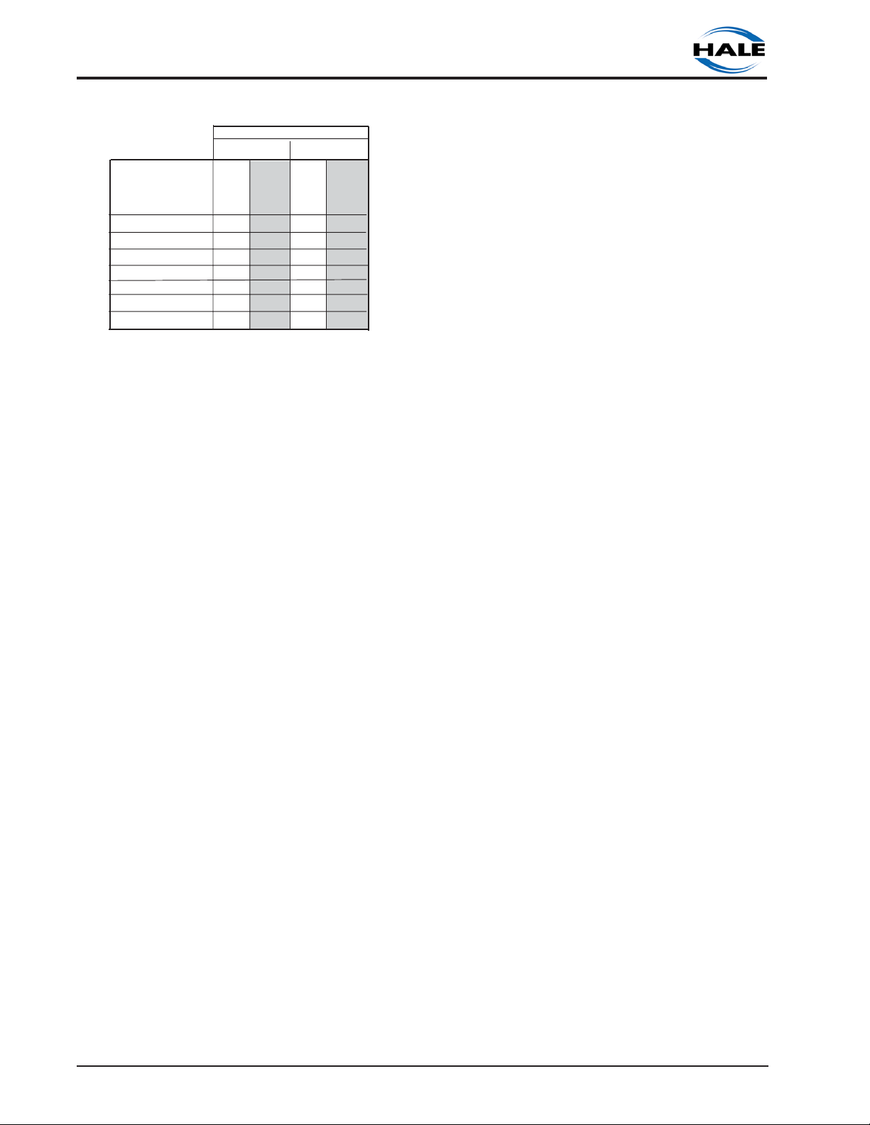
There are two models of Hale Foam systems
covered by this manual. The Hale
FoamLogix Model 3.3 and Model 5.0. The
maximum rated foam concentrate flow in
gallons per minute is denoted by the model
number. Table 1 shows system capacities
at various foam concentrate injection rates
for the different Hale Foam Models.
Hale Foam systems can be configured to
operate with single or dual foam
Section I: Description
Ι-3
ROTARY GEAR PUMP
ELECTRONIC FOAM PROPORTIONING SYSTEM
Table 1. Maximum Foam Solution Flows
WATER FLOW
MODEL 3.3 MODEL 5.0
FOAM
CONCENTRATE
(%)
0.1
0.2
0.3
0.5
1
3
6
concentrate tanks. Examples of the various
Hale Foam system configurations are shown
in figures 1-1 through 1-7 at the end of this
section.
The available Air Dual Tank (ADT) valve for
the Hale Foam system is an air operated
foam tank selector valve that provides
selection of foam concentrate dependent
on fire ground operational demands. The
ADT is an integral part of the foam pump
and provides an electrical interlock for the
low tank level sensors and concentrate
injection rate. A panel mounted selector
toggle switch with indicator lights controls
foam concentrate tank selection and shows
which foam concentrate tank is in use.
The Manual Dual Tank (MDT ΙΙ) selector
valve is available for the Hale Foam systems
with dual tanks. The MDT ΙΙ is a panel
mounted manually operated selector that
provides selection of foam concentrate
dependent on fire ground operational
demands. The MDT ΙΙ also provides an
electrical interlock for the low tank level
sensors and concentrate injection rate. It
should be noted that the MDT ΙΙ is not
suitable for top mount operator panel
installations and some side operator panels
due to gravity feed requirements of foam
concentrate to the foam pump.
Selection of the desired foam concentrate
tank with the ADT panel mounted toggle
switch or MDT ΙΙ selector will automatically
GPM LPM
3300 12491
1650 6245
1100 4164
660 2498
330 1249
110 416
55 208
GPM LPM
5000 18925
2500 9463
1667 6310
1000 3785
500 1893
167 632
83 314
change the foam concentrate injection
rate to the preset default rate for the
selected foam tank. No further operator
intervention is required.
Single tank foam systems can be
configured with a Manual Single Tank (MST)
selector which provides a flush function
connection to the foam system electronic
controls.
The ADT, MDT ΙΙ and MST all provide the
check valves and connection points to
provide foam pump flushing capabilities.
Strainers available for Hale FoamLogix Foam
systems protect the foam pump from debris
that might accumulate in the foam
concentrate tank. The standard in-line
strainer/valve assembly has a composite
nonmetallic housing with stainless steel
mesh strainer element. It is provided with a
service shutoff valve, mounting bracket.
The strainer and valve have 1-1/4 NPT
threads and is supplied with fittings for
connection of either 1-1/4 inch (32 mm) ID,
1 inch (25 mm) ID or ¾ inch (19 mm) ID
foam concentrate suction hose. The in-line
strainer/valve assembly is suitable for use
with both Class A and Class B foam
concentrates. The in-line strainer/valve
assembly is designed for installations where
the strainer is mounted in the foam pump
suction line and IS NOT subject to flushing
water pressure.
Hale FS series strainers are panel mounted
strainers with a 500 PSIG (34 BAR) pressure
rating suitable for use where flushing water
pressure will go through the strainer. The
FS15 strainer has ¾ inch NPT connection
ports and a 1-½ inch NST cap and is suitable
for use with Class A and low viscosity Class B
foam concentrates. The FS25 strainer has 1
inch NPT connection ports and a 2-½ inch
NST cap and is suitable for use with both
Class A and Class B foam concentrates.
All Hale FoamLogix Foam systems require a
flowsensor for operation.
Ι−4
Section I: Description

ELECTRONIC FOAM PROPORTIONING SYSTEM
Ordering of Hale Foam systems is simple.
Using the current Hale FoamLogix Foam
System Price List and Order Form helps
ensure a
provided to the end user.
Use the following procedure when ordering
a Hale FoamLogix Foam system. Following
all the steps ensures a complete system will
be ordered:
1. Check Hale Foam system product
information update (Bulletin 961) for the
latest information and advice for foam
system selection.
2. Determine the type of foam
concentrate to be used in the system
and ensure system compatibility by
referring to the Hale Foam Concentrate
Compatibility list (Bulletin #650).
3. Determine the Hale Foam system
desired (Model 5.0 or Model 3.3; 12 VDC
or 24 VDC motor).
4. Determine tank selector desired based
on the number of foam concentrate
tanks installed (ADT or MDT ΙΙ for dual
tank systems; MST or No Selector for
single tank systems).
5. Determine strainers desired (In-line
Strainer/Valve Assembly, FS 15 Strainer
or FS 25 Strainer).
6. Determine the low tank level sensors
desired (Side Mount, Bottom Mount or
Top Mount Assembly).
7. Select the flowsensor then the mounting
weld fitting or saddle clamp based on
discharge pipe size. Select flowsensor
cable length (10 feet, 20 feet or 30 feet).
8. Determine additional Hale components
that enhance system operation and
ease installation (Control Cable
Extension, Waterway Check Valves,
Manifolds, Flanges, etc.).
complete matched system is
ROTARY GEAR PUMP
Components shown in Bold type above
represent the best value performance
system. System components are shown in
the following system configuration section.
All components listed have been
engineered and tested with Hale Foam
systems to provide optimum system
performance. Using the information
provided in this manual section and the
detailed ordering procedures on the option
order form ensures a complete Hale Foam
system is ordered thus eliminating delays
caused by missing components.
Section I: Description
Ι-5
ROTARY GEAR PUMP
ELECTRONIC FOAM PROPORTIONING SYSTEM
HALE FOAM SYSTEM SPECIFICATIONS
Foam Pump................................................................................. Rotary Gear Positive Displacement
Rated Foam Concentrate Output
Model 3.3 ........................................................................................................ 3.3 GPM (12 LPM)
Model 5.0 ........................................................................................................ 5.0 GPM (19 LPM)
Maximum System Operating Pressure
Model 3.3 ......................................................................................................... 400 PSI (28 BAR)
Model 5.0 ......................................................................................................... 250 PSI (17 BAR)
Maximum Operating Temperature ................................................................................. 160OF (71 C)
Pump Motor.................................................................................¾ HP (0.5 kW), 12 VDC (Standard)
¾ HP (0.5 kW), 24 VDC (Optional)
Operating Ampere Draw ...............................................30 AMPS @ 12 VDC (15 AMPS @ 24 VDC)
Maximum Ampere Draw ...............................................60 AMPS @ 12 VDC (30 AMPS @ 24 VDC)
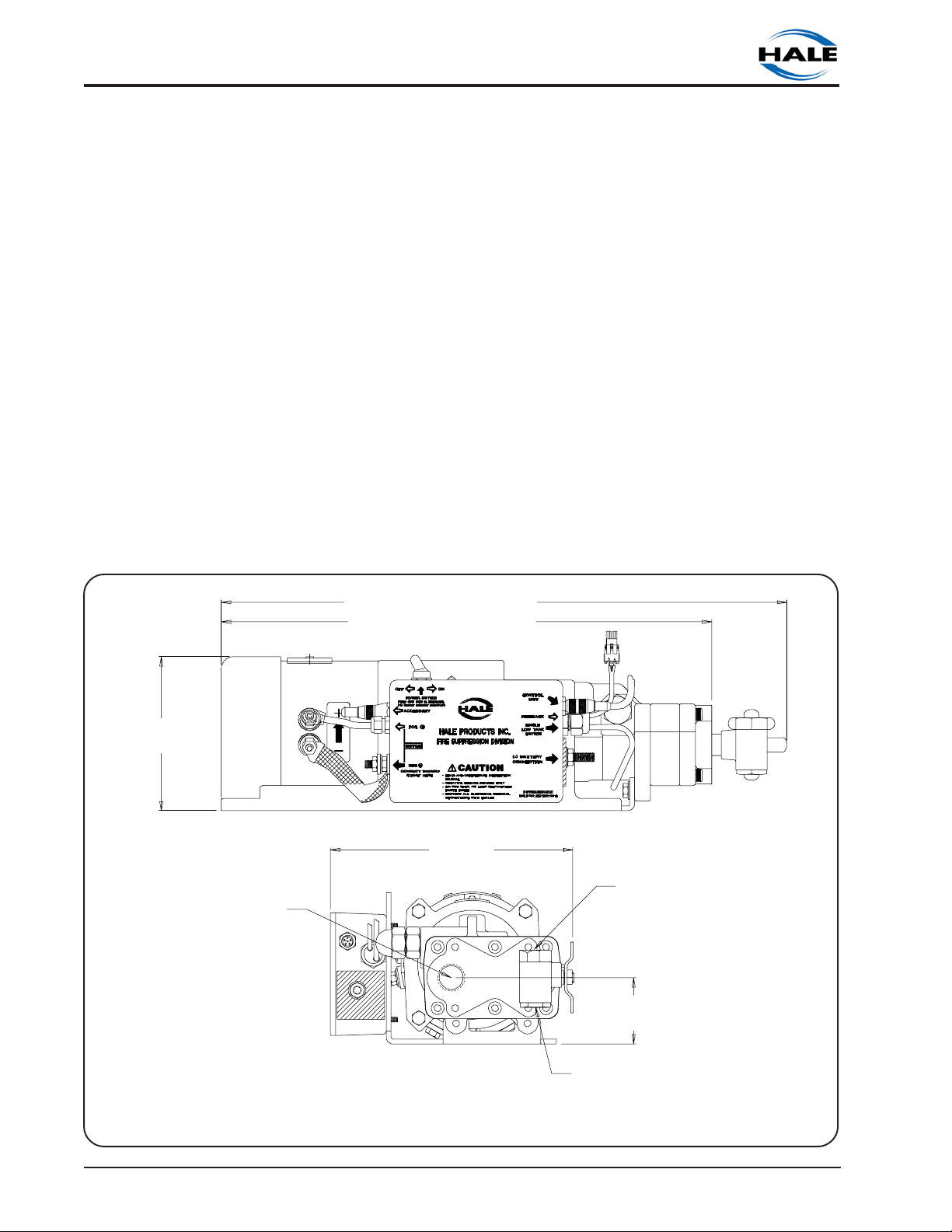
6.02 IN.
(153 MM)
¾ INCH NPT SUCTION
HOSE CONNECTION
MODEL 5.0: 22.00 IN. (559 MM)
MODEL 3.3: 21.75 IN. (552 MM)
MODEL 5.0: 19.07 IN. (484 MM)
MODEL 3.3: 18.82 IN. (478 MM)
9.43 IN.
(240 MM)
½ INCH NPT INJECT
HOSE CONNECTION
2.58 IN.
(66 MM)
Ι−6
½ INCH NPT BYPASS HOSE
CONNECTION
Foam Pump Installation Envelope Dimensions
Configured for use with MDT ΙΙ, MST or No Tank Selector Option
Section I: Description
ROTARY GEAR PUMP
ELECTRONIC FOAM PROPORTIONING SYSTEM
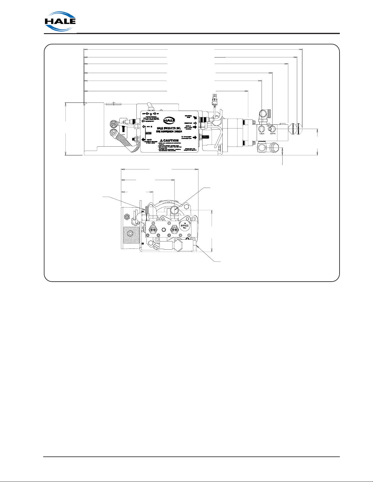
6.02 IN.
(153 MM)
TANK A CONNECTION
¾ INCH I.D. HOSE
6.20 IN.
(157 MM)
3.70 IN.
(94 MM)
MODEL 5.0: 25.37 IN. (644 MM)
MODEL 3.3: 25.12 IN. (638 MM)
MODEL 5.0: 24.74 IN. (628 MM)
MODEL 3.3: 24.94 IN. (622 MM)
MODEL 5.0: 23.70 IN. (602 MM)
MODEL 3.3: 23.45 IN. (596 MM)
MODEL 5.0: 21.88 IN. (555 MM)
MODEL 3.3: 21.63 IN. (549 MM)
MODEL 5.0: 20.63 IN. (524 MM)
MODEL 3.3: 20.38 IN. (518 MM)
MODEL 5.0: 19.07 IN. (484 MM)
MODEL 3.3: 18.82 IN. (478 MM)
8.95 IN.
(227 MM)
BYPASS HANDLE: BYPASS POSITION
BYPASS HANDLE: INJECT POSITION
INJECT PORT: ½ INCH NPT
BYPASS PORT: ½ INCH NPT
TO CENTER OF FLUSH
WATER INLET CONNECTION
TANK B CONNECTION
1 INCH I.D. HOSE
3.02 IN.
(77 MM)
0.87 IN. (22 MM)
4.76 IN.
(121 MM)
FLUSH WATER CONNECTION
½ INCH NPT
Foam Pump Installation Envelope Dimensions Configured with Optional ADT
Section I: Description
Ι-7
ROTARY GEAR PUMP
ELECTRONIC FOAM PROPORTIONING SYSTEM
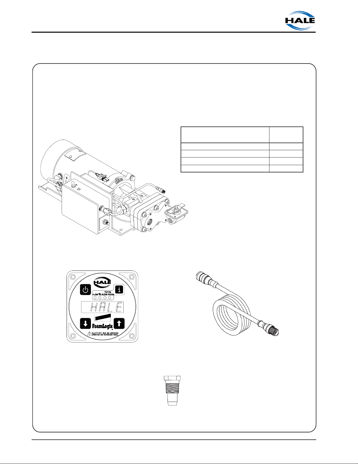
SYSTEM CONFIGURATION
Hale Foam Proportioner System Model
(Model 3.3 or Model 5.0)
All Hale Foam systems include: Foam Pump/Motor Assembly, Control Unit, Control Cable
and Check Valve/Injector Fitting
LEDOMXIGOLMAOF
ROTOMCDV21/W0.5XIGOLMAOF0-51-0313-105
ROTOMCDV42/W0.5XIGOLMAOF0-42-0313-105
ROTOMCDV21/W3.3XIGOLMAOF0-51-0213-105
ROTOMCDV42/W3.3XIGOLMAOF0-42-0213-105
TRAP
REBMUN
Foam Pump/Motor Assembly
(Shown with Bypass Valve when configured for MDT ΙΙ, MST or no tank selector option)
Ι−8
Control Unit
P/N 107064
Optional 6-Pin Extension Cable
16.5 Feet (P/N 013-2020-05-0)
6.5 Feet (P/N 013-2020-02-0)
Check Valve/Injector Fitting
P/N 038-1790-00-0
Section I: Description
ROTARY GEAR PUMP
ELECTRONIC FOAM PROPORTIONING SYSTEM
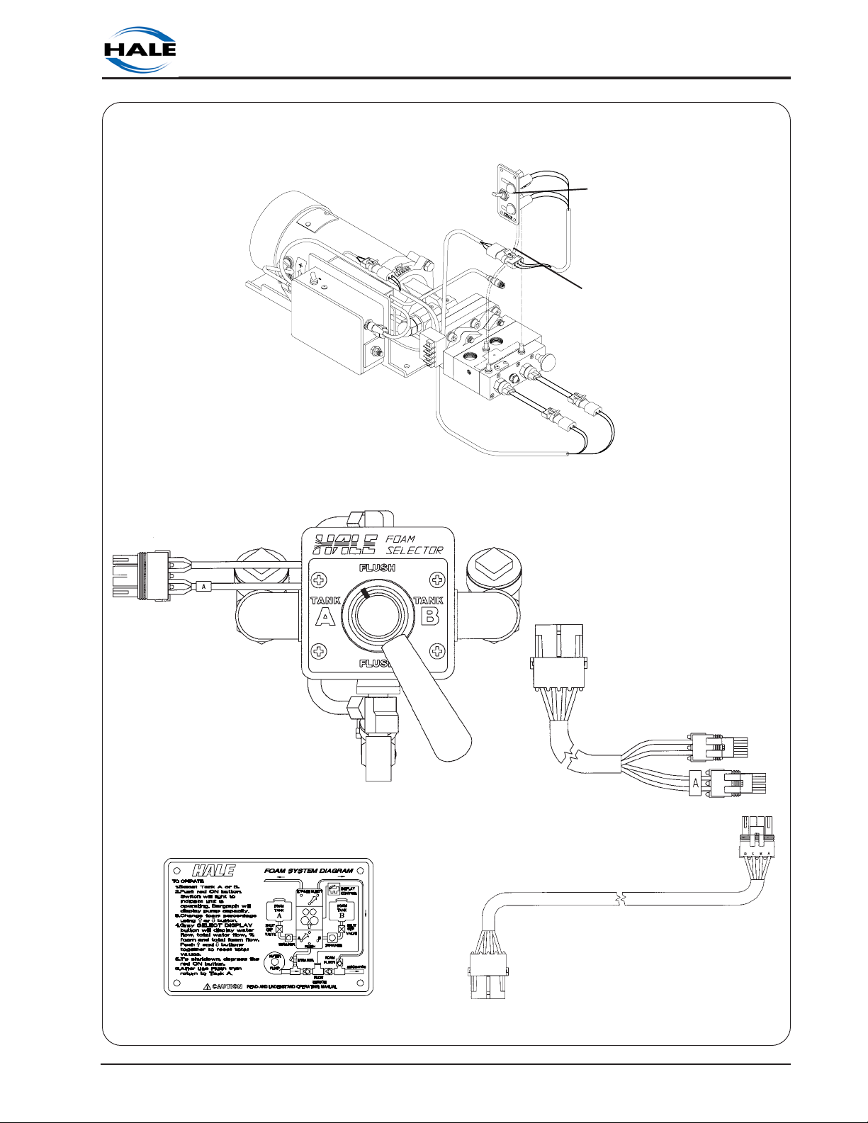
Dual Foam Concentrate Tank System Options
Panel Switch/Indicator
Light Placard Assembly
Optional Color Coded Air
Connection Harness
(P/N 507-0380-00-0)
Foam Pump/Motor Assembly with Air Dual Tank (ADT) Selector
(P/N 538-1640-02-0)
Manual Dual Tank (MDT ΙΙ) Selector and Wiring Harness
(P/N 538-1490-11-0)
Dual Tank Instruction Placard/System
Diagram (P/N 101-1631-07-0)
Section I: Description
MDT ΙΙ Wiring Harness Extension
(P/N 513-0320-02-0)
Ι-9
ROTARY GEAR PUMP
ELECTRONIC FOAM PROPORTIONING SYSTEM
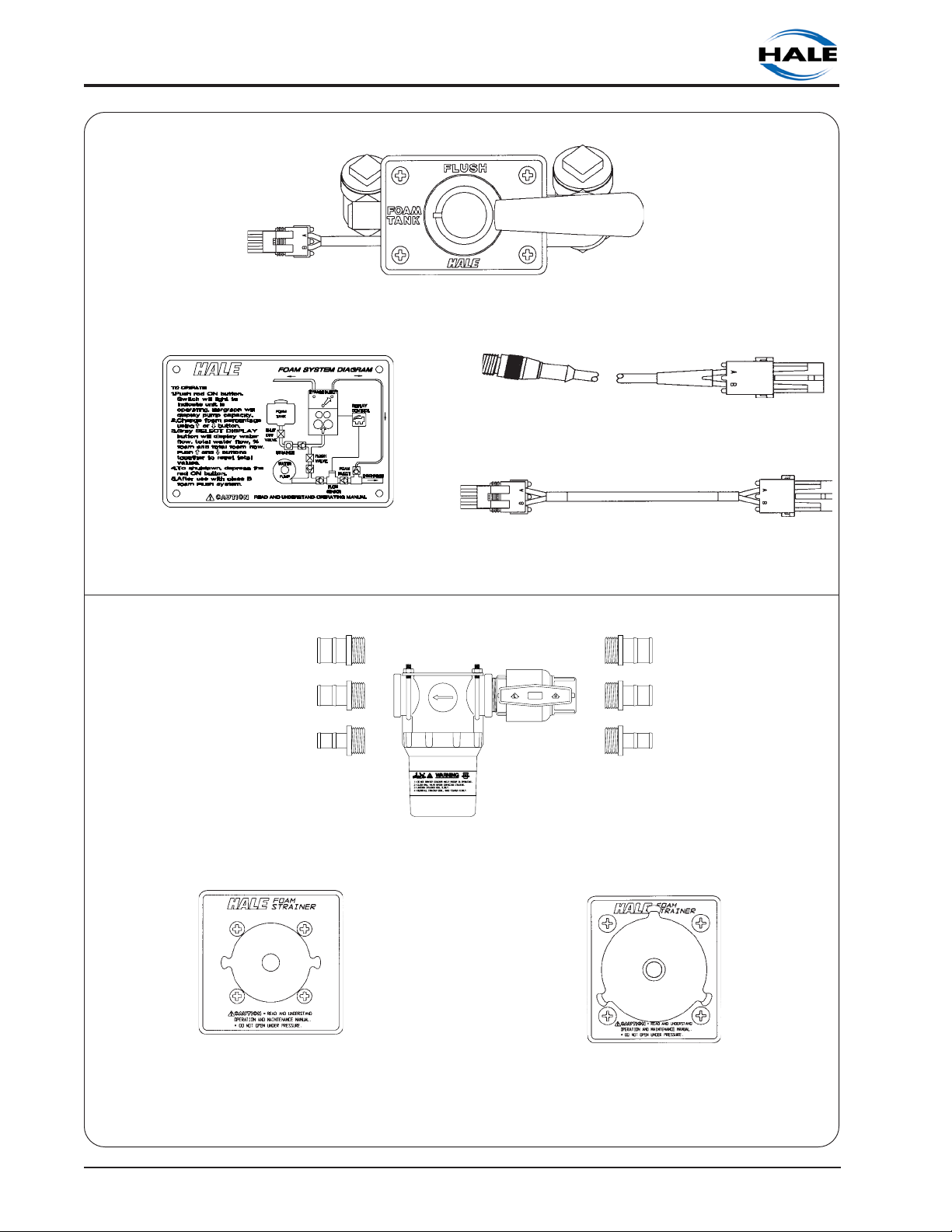
Single Foam Concentrate Tank Options
Manual Single Tank (MST) Selector
Provides FoamPump Flushing Capabilities for a Single Tank System
(P/N 538-1490-12-0)
MST Wiring Harness
(P/N 513-0320-04-0)
Single Tank Instruction Placard/System
Diagram
(P/N 101-1631-12-0)
Foam Concentrate Strainers
In-Line Strainer/Valve Assembly (P/N 510-0190-01-0)
(Do Not Use If Subject to Flushing Water Pressure)
MST Wiring Harness Extension
72 inches (1829 mm) long
(P/N 513-0320-07-0)
FS-15 STRAINER (P/N 510-0150-00-0)
(¾ Inch NPT Threads. Use With Class A
and thin Class B Foam Concentrates)
Hale FS Series Strainers (Use When Strainer is Subjected to Flushing Water Pressure)
Ι−10
FS-25 STRAINER (P/N 510-0180-00-0)
(1 Inch NPT Threads. Use With Class A
and Class B Foam Concentrates)
Section I: Description
ELECTRONIC FOAM PROPORTIONING SYSTEM
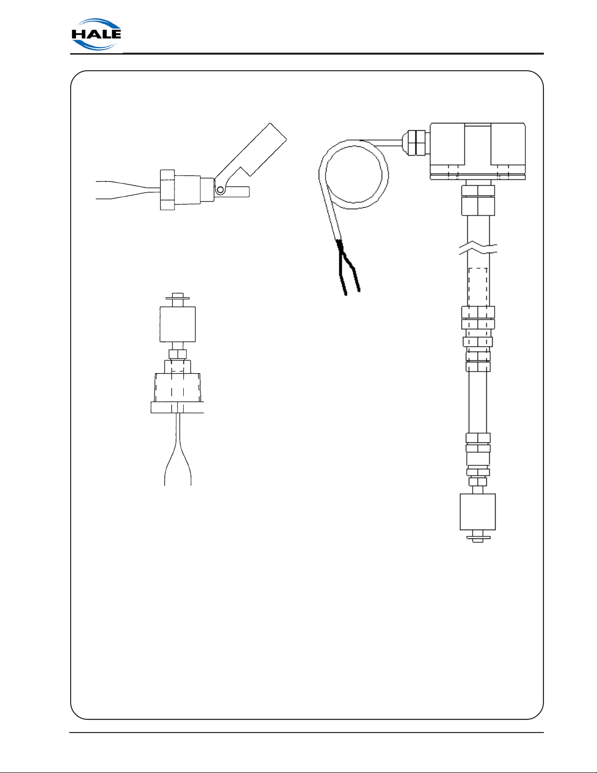
Low Tank Level Sensor Options
(One Low Tank Level Sensor is Required for Each Foam Tank)
Side Mount Low Tank Level Sensor
(P/N 200-2110-02-0)
(½ Inch NPT Threaded Bushing to Mount
From Outside Foam Tank)
ROTARY GEAR PUMP
Brass Bottom Mount Low Tank Level
Sensor
(P/N 200-2110-04-0)
(1 Inch NPT Threaded Bushing to Mount
From Outside Foam Tank)
Section I: Description
Top Mount Low Tank Level Sensor
Assembly
(P/N 200-2110-06-0)
(Extends From 2-½ Feet to 5 Feet Long.
May be Cut Shorter)
Ι-11
ROTARY GEAR PUMP
ELECTRONIC FOAM PROPORTIONING SYSTEM
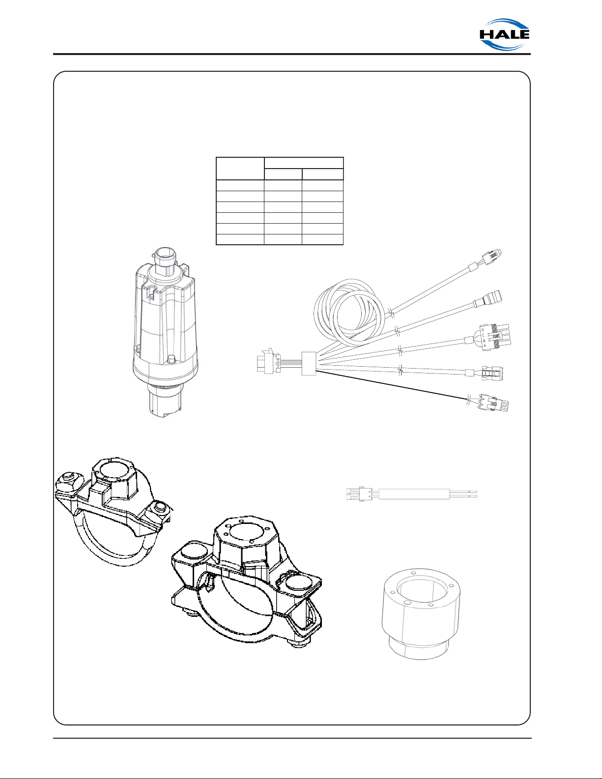
Flowsensors
Each Hale foam system requires a flowsensor to operate. Pipe size must be selected based
on the minimum and maximum water flow in the foam capable discharge. Following is a
list of pipe size and rated flow range along with flowsensor saddle clamp part number: In
all instances a weld fitting may be substituted for the saddle clamp.
EZISEPIP
HCNI2/1-1033-019421-83
HCNI2055-022802-67
HCNI2/1-2008-038203-411
HCNI30521-051374-981
HCNI40081-573186-482
MPGMPL
VCDroVCS057-039382-411
EGNARWOLF
Flowsensor Paddlewheel
P/N 102714
Flowsensor Saddle Clamp
2 INCH P/N 4842010
2-1/2 INCH P/N 4843010
3 INCH P/N 4844010
4 INCH P/N 4846010
Flowsensor Cable
10 Feet P/N 107400
20 Feet P/N 107362
30 Feet P/N 107401
Wiring Harness
P/N 513-0270-04-0
Flowsensor Weld Fitting
Stainless Steel P/N 082-3060-00-0
Steel P/N 309020
Aluminium P/N 309010
Ι−12
Section I: Description
ROTARY GEAR PUMP
ELECTRONIC FOAM PROPORTIONING SYSTEM
Check Valve Manifolds
The check valve manifolds include Flowsensor, Check Valve/Injector fitting and single or
dual waterway check valve flappers. End connections for the manifolds are 3 inch victaulic.
DUAL CHECK VALVE (DCV) MANIFOLD
P/N 108751
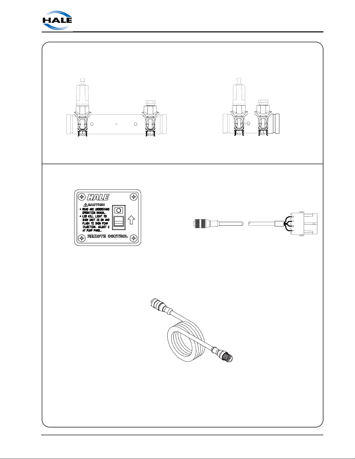
Remote Activation Switch
Remote Activation Switch
(P/N 513-0330-01-0)
SINGLE CHECK VALVE (SCV) MANIFOLD
P/N 108893
Remote Activation Switch Cable
16 Feet (P/N 513-0680-00-0)
Section I: Description
4-Pin Extension Cable
6 Feet (P/N 013-2010-02-0)
16 Feet (P/N 013-2010-05-0)
32 Feet (P/N 013-2010-10-0)
Ι-13
ROTARY GEAR PUMP
ELECTRONIC FOAM PROPORTIONING SYSTEM
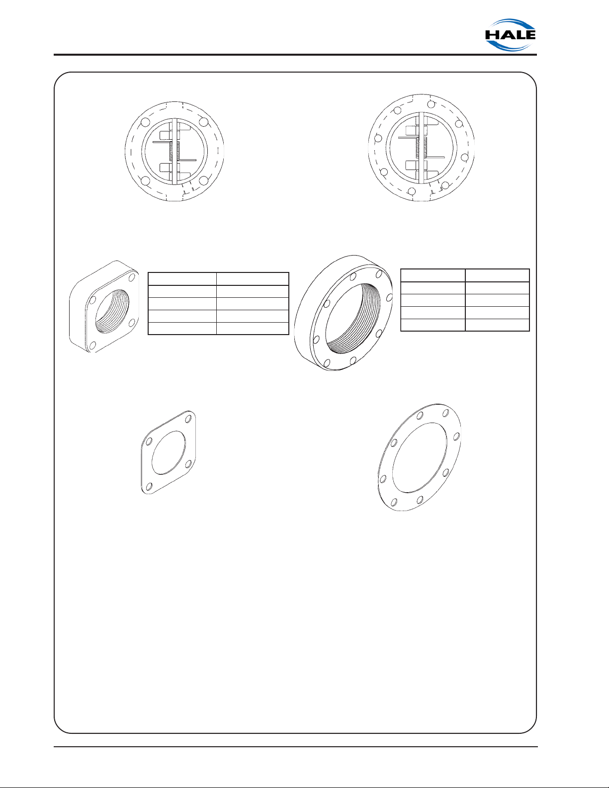
Check Valves, Flanges and Gaskets
3 Inch "115" Check Valve
(P/N 038-1570-00-0)
SDAERHTREBMUNTRAP
TPNHCNI30-00-0800-511
TPNHCNI2/1-20-00-0700-511
TPNHCNI20-00-0600-511
KNALB0-00-0500-511
Type 115 Flange
Use 3 and 2-½ inch NPT with 3 inch check valves.
Also available with 1-½ and 2 inch NPT threads.
4 Inch "2433D" Check Valve
(P/N 038-1570-04-0)
SDAERHTREBMUNTRAP
TPNHCNI40-00-0400-511
TPNHCNI30-00-0300-511
TPNHCNI2/1-20-00-0200-511
KNALB0-00-0100-511
Type 2433D Flange
Use 4 inch NPT with 4 inch check valves.
Also available with 2-½ and 3 inch NPT threads.
Ι−14
115 GASKET
(P/N 046-0050-00-0)
2433D GASKET
(P/N 046-0040-00-0)
Section I: Description
ELECTRONIC FOAM PROPORTIONING SYSTEM
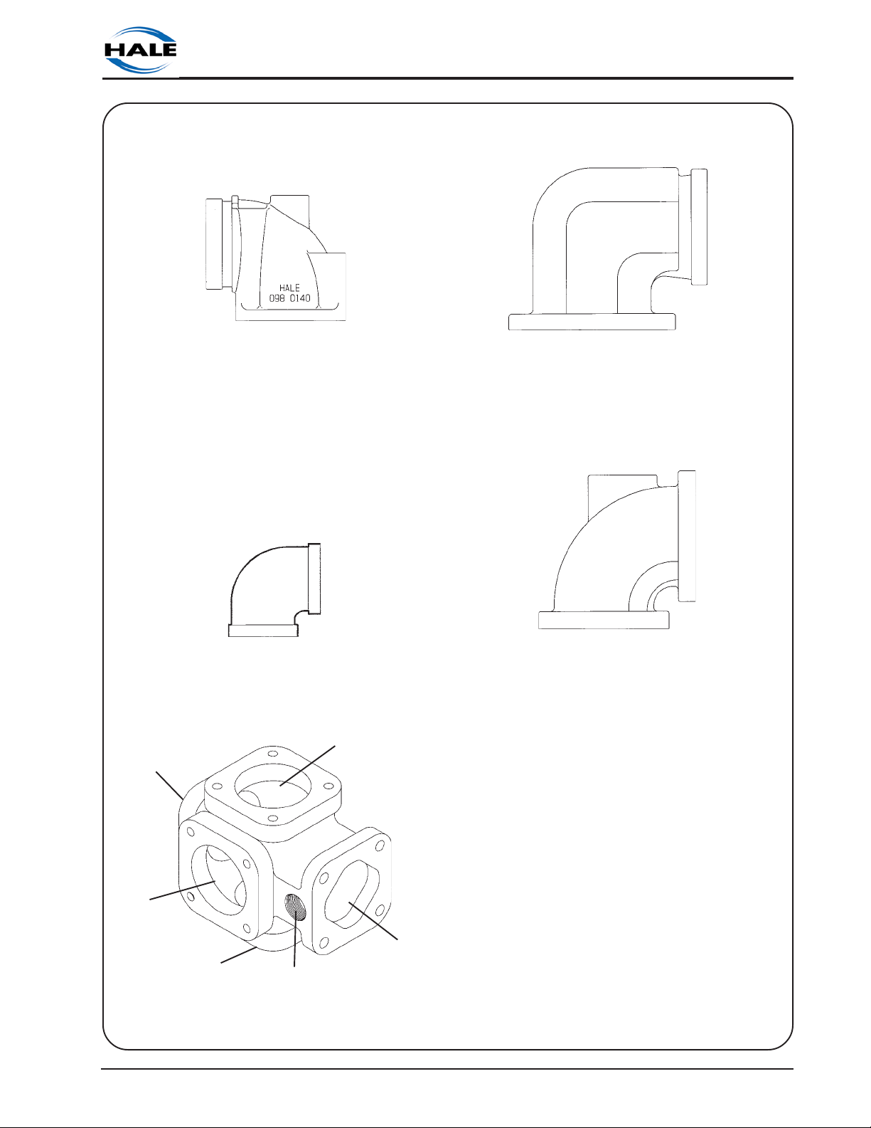
Elbows and Mini Manifold
ROTARY GEAR PUMP
Close Fit Flanged Elbow
(P/N 098-0140-00-0)
115 flange inlet with 3 inch Victaulic outlet.
Close Fit Flanged Elbow
(P/N 098-0050-00-0)
115 flange inlet with 2-½ inch female NPT outlet.
OUTLET
OUTLET
Close Fit Flanged Elbow
(P/N 098-0190-00-0)
2433D flange inlet with 3 inch female NPT
and 4 inch Victaulic outlet.
Close Fit Flanged Elbow
(P/N 098-0020-00-0)
115 flange inlet with 115 flange outlet.
OUTLET
OUTLET
Mini Manifold
(P/N 178-0320-02-0)
Section I: Description
INLET
FOAM
INJECTION
Ι-15
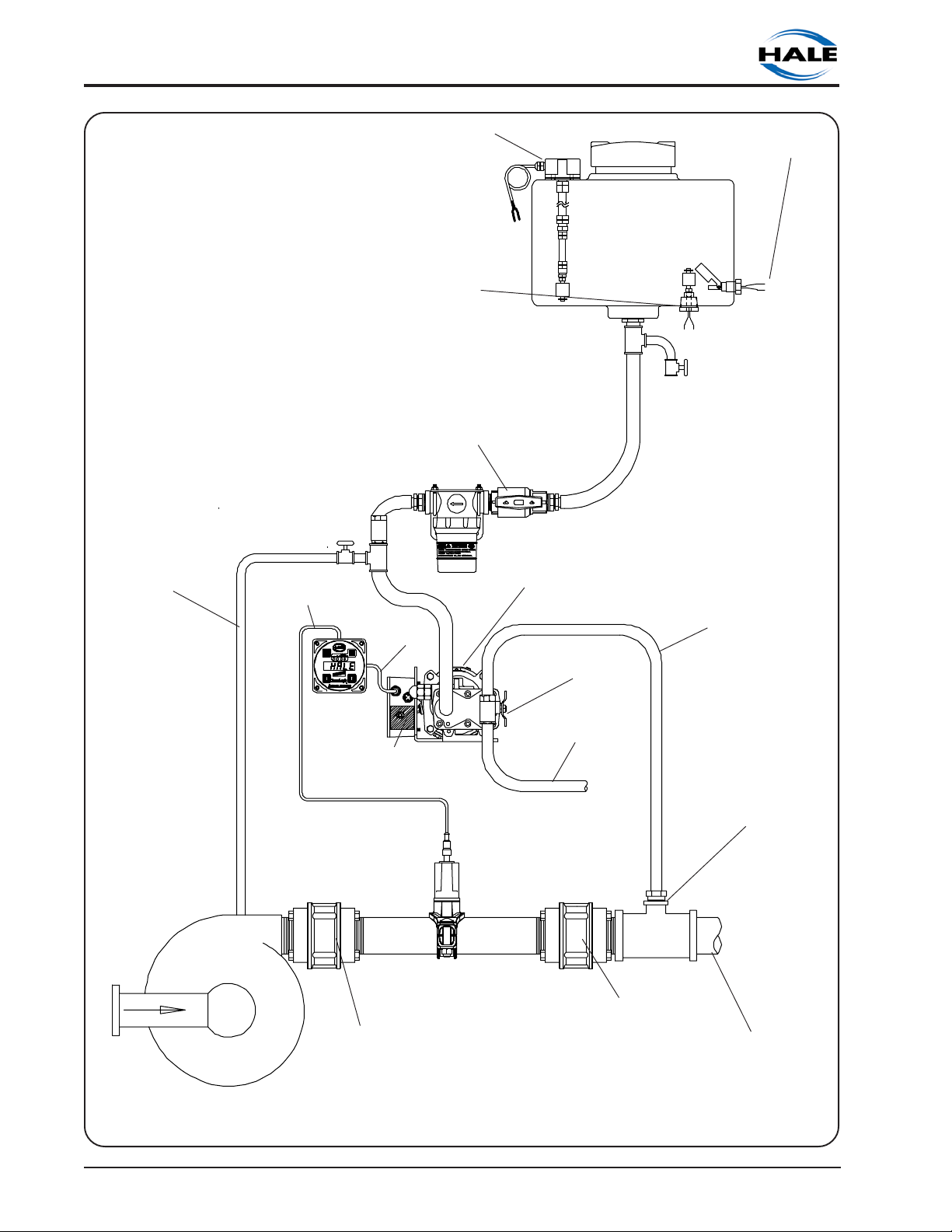
ROTARY GEAR PUMP
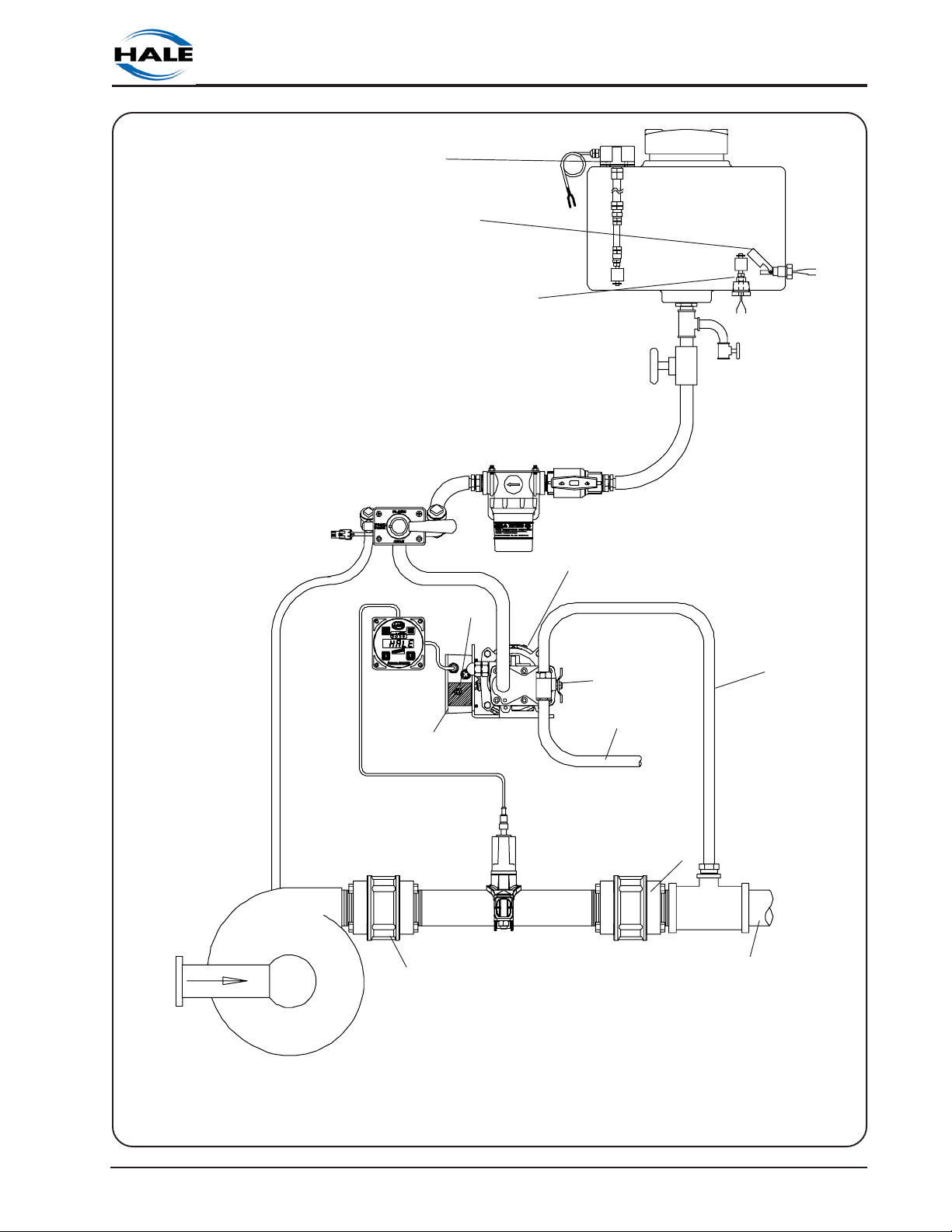
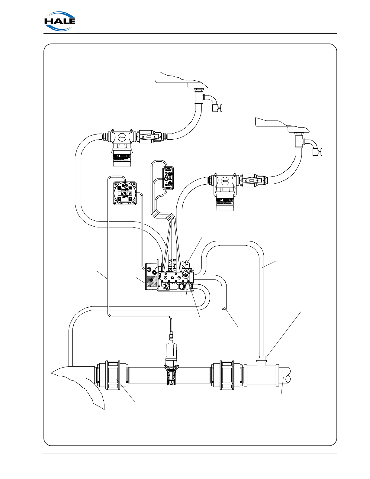
ELECTRONIC FOAM PROPORTIONING SYSTEM
FLUSHING
WATER SUPPLY
BOTTOM MOUNT FOAM
FLOWSENSOR
CORDSET
TOP MOUNT FOAM
TANK LOW LEVEL
SENSOR OPTION
TANK LOW LEVEL
SENSOR OPTION
IN-LINE FOAM STRAINER/
VALVE ASSEMBLY
CONTROL
CORDSET
FOAM PUMP AND
MOTOR
ASSEMBLY
SIDE MOUNT FOAM
TANK LOW LEVEL
SENSOR OPTION
FOAM
TANK
FOAM TANK
DRAIN
VALVE
FOAM
INJECTION
HOSE
FIRE
PUMP
CONTROL
UNIT
DISTRIBUTION
WATERWAY
CHECK
VALVE
BOX
HALE
FLOWSENSOR
PADDLE WHEEL
MOUNTED IN
SADDLECLAMP
BYPASS
VALVE
BYPASS
HOSE
WATERWAY
CHECK
VALVE
CHECK VALVE
INJECTOR
FITTING
FOAM SOLUTION
DISCHARGE(S)
Ι−16
Figure 1-1. Hale Foam System Layout with Single Foam Concentrate Tank
Section I: Description
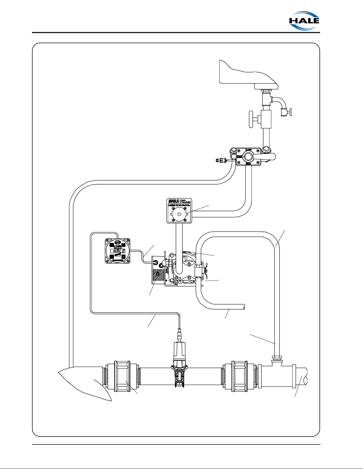
TOP MOUNT FOAM
TANK LOW LEVEL
SENSOR OPTION
SIDE MOUNT FOAM
MST
SELECTOR
VALVE
ELECTRONIC FOAM PROPORTIONING SYSTEM
TANK LOW LEVEL
SENSOR OPTION
BOTTOM MOUNT FOAM
TANK LOW LEVEL
SENSOR OPTION
IN-LINE FOAM STRAINER/
ROTARY GEAR PUMP
FOAM
TANK
FOAM TANK
DRAIN
VALVE
VALVE ASSEMBLY
FLUSHING
WATER SUPPLY
FIRE
PUMP
CONTROL
CORDSET
CONTROL
UNIT
DISTRIBUTION
BOX
WATERWAY
CHECK
VALVE
FOAM PUMP AND
MOTOR
ASSEMBLY
BYPASS
VALVE
BYPASS
HOSE
HALE
FLOWSENSOR
PADDLE WHEEL
MOUNTED IN
SADDLECLAMP
WATERWAY
CHECK
VALVE
FOAM
INJECTION
HOSE
CHECK VALVE
INJECTOR
FITTING
FOAM SOLUTION
DISCHARGE(S)
Figure 1-2. Hale Foam System Layout with Single Foam Concentrate Tank, MST and In-
line Strainer/Valve Assembly
Section I: Description
Ι-17
ROTARY GEAR PUMP
ELECTRONIC FOAM PROPORTIONING SYSTEM
FOAM TANK
SHUTOFF
MST
SELECTOR
VALVE
VALVE
FOAM
TANK
FOAM TANK
DRAIN
VALVE
CONTROL
FLUSHING
WATER SUPPLY
FIRE
PUMP
UNIT
CONTROL
CORDSET
DISTRIBUTION
BOX
FLOWSENSOR
CORDSET
FS-15 OR FS-25 PANEL
MOUNTED FOAM
STRAINER
FOAM PUMP AND
MOTOR
ASSEMBLY
BYPASS
VALVE
BYPASS
HOSE
CHECK VALVE
HALE
FLOWSENSOR
PADDLE WHEEL
MOUNTED IN
SADDLECLAMP
INJECTOR
FITTING
FOAM
INJECTION
HOSE
WATERWAY
CHECK
VALVE
WATERWAY
CHECK
VALVE
FOAM SOLUTION
DISCHARGE(S)
Figure 1-3. Hale Foam System Layout with Single Foam Concentrate Tank, MST and FS
Series Strainer
Ι−18
Section I: Description
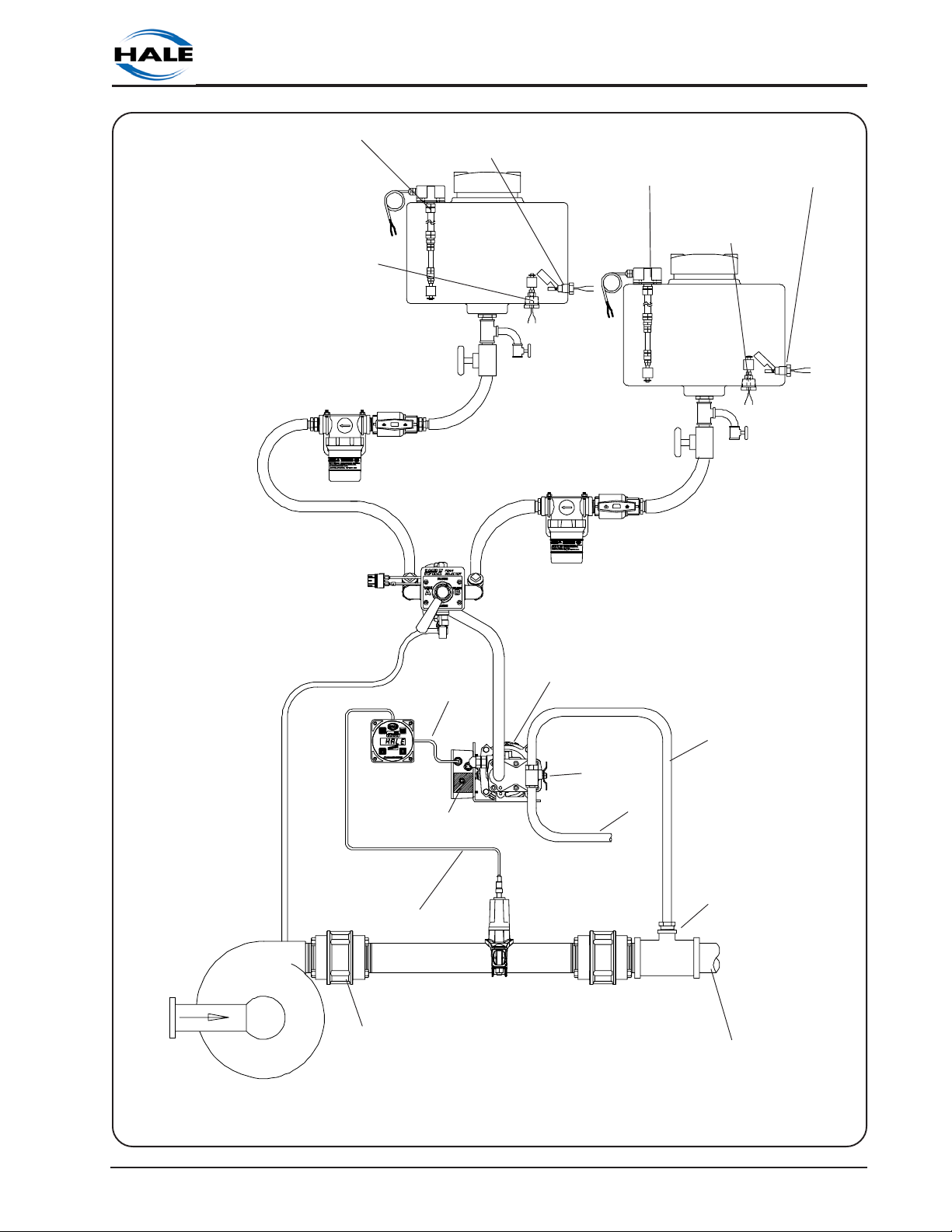
ROTARY GEAR PUMP
ELECTRONIC FOAM PROPORTIONING SYSTEM
TOP MOUNT FOAM
TANK LOW LEVEL
SENSOR OPTION
BOTTOM MOUNT FOAM
TANK LOW LEVEL
SENSOR OPTION
IN-LINE FOAM STRAINER/
VALVE ASSEMBLY
SIDE MOUNT FOAM
TANK LOW LEVEL
SENSOR OPTION
FOAM
TANK A
MDT II
SELECTOR
VALVE
FOAM TANK
DRAIN
VALVE
TOP MOUNT FOAM
TANK LOW LEVEL
SENSOR OPTION
BOTTOM MOUNT FOAM
TANK LOW LEVEL
SENSOR OPTION
FOAM
TANK B
IN-LINE FOAM STRAINER/
VALVE ASSEMBLY
SIDE MOUNT FOAM
TANK LOW LEVEL
SENSOR OPTION
FOAM TANK
DRAIN
VALVE
FLUSHING
WATER SUPPLY
FIRE
PUMP
CONTROL
UNIT
FLOWSENSOR
CORDSET
WATERWAY
CHECK
VALVE
CONTROL
CORDSET
DISTRIBUTION
BOX
FOAM PUMP AND
MOTOR
ASSEMBLY
BYPASS
VALVE
BYPASS
HALE
FLOWSENSOR
PADDLE WHEEL
MOUNTED IN
SADDLECLAMP
WATERWAY
CHECK
VALVE
FOAM
INJECTION
HOSE
HOSE
CHECK VALVE
INJECTOR
FITTING
FOAM SOLUTION
DISCHARGE(S)
Figure 1-4. Hale Foam System Layout with Dual Foam Concentrate Tanks, MDT ΙΙ and In-
line Strainer/Valve Assembly
Section I: Description
Ι-19
ROTARY GEAR PUMP
ELECTRONIC FOAM PROPORTIONING SYSTEM
TOP MOUNT FOAM
TANK LOW LEVEL
SENSOR OPTION
FOAM TANK
SHUTOFF
VALVE
FOAM
TANK A
SIDE MOUNT FOAM
TANK LOW LEVEL
SENSOR OPTION
BOTTOM MOUNT FOAM
TANK LOW LEVEL
SENSOR OPTION
FOAM TANK
DRAIN VALVE
MDT II
SELECTOR
VALVE
TOP MOUNT FOAM
TANK LOW LEVEL
SENSOR OPTION
FOAM TANK
SHUTOFF
VALVE
SIDE MOUNT FOAM
TANK LOW LEVEL
SENSOR OPTION
FOAM
TANK B
BOTTOM MOUNT FOAM
TANK LOW LEVEL
SENSOR OPTION
FOAM TANK
DRAIN VALVE
FLUSHING
WATER SUPPLY
FIRE
PUMP
CONTROL
UNIT
FLOWSENSOR
CORDSET
WATERWAY
CHECK
VALVE
CONTROL
CORDSET
DISTRIBUTION
BOX
FS-15 OR FS-25 PANEL
MOUNTED FOAM
STRAINER
FOAM PUMP AND
MOTOR
ASSEMBLY
BYPASS
VALVE
BYPASS
HOSE
HALE
FLOWSENSOR
PADDLE WHEEL
MOUNTED IN
SADDLECLAMP
WATERWAY
CHECK
VALVE
FOAM
INJECTION
HOSE
CHECK VALVE
INJECTOR
FITTING
FOAM SOLUTION
DISCHARGE(S)
Figure 1-5. Hale Foam System Layout with Dual Foam Concentrate Tanks, MDT ΙΙ and FS
Series Strainer Assembly
Ι−20
Section I: Description
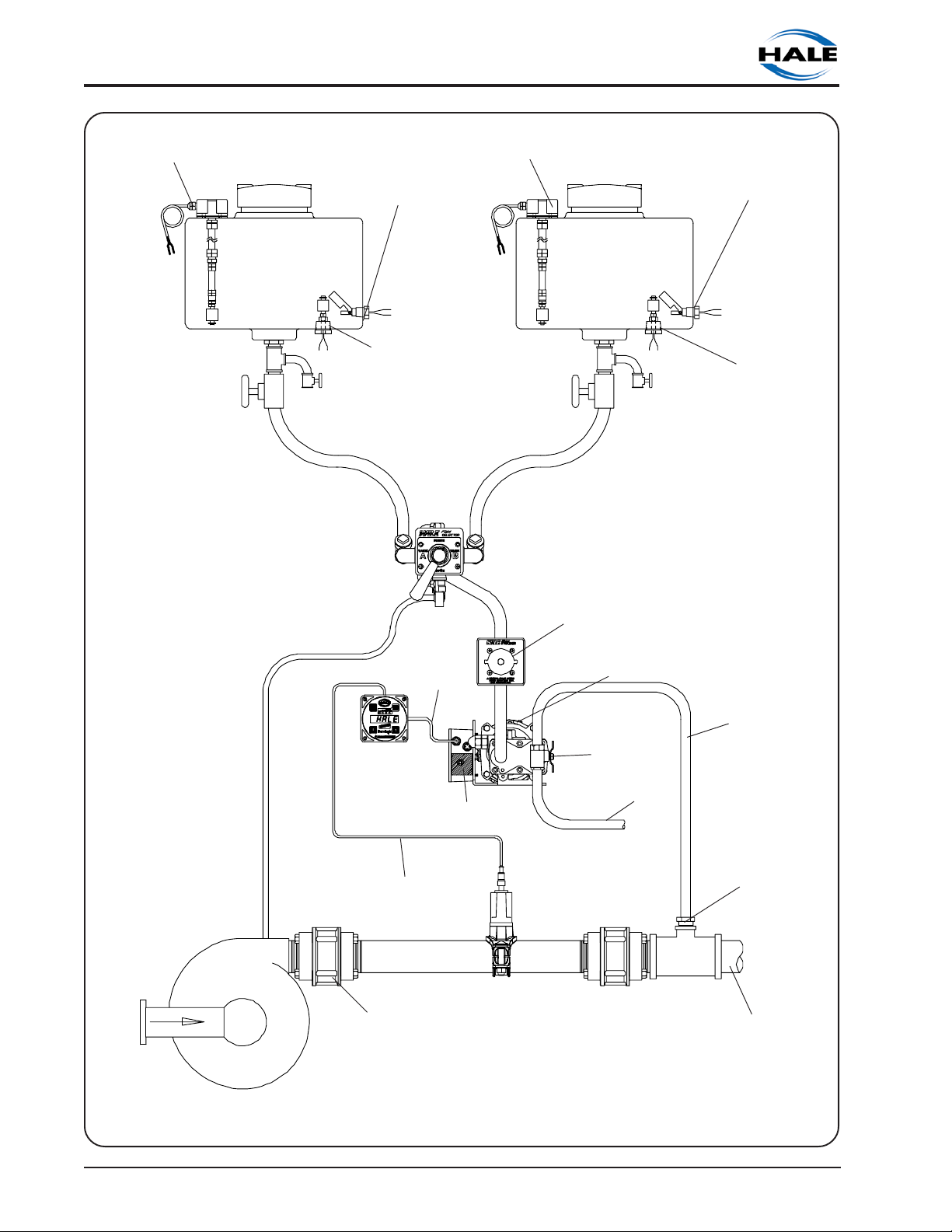
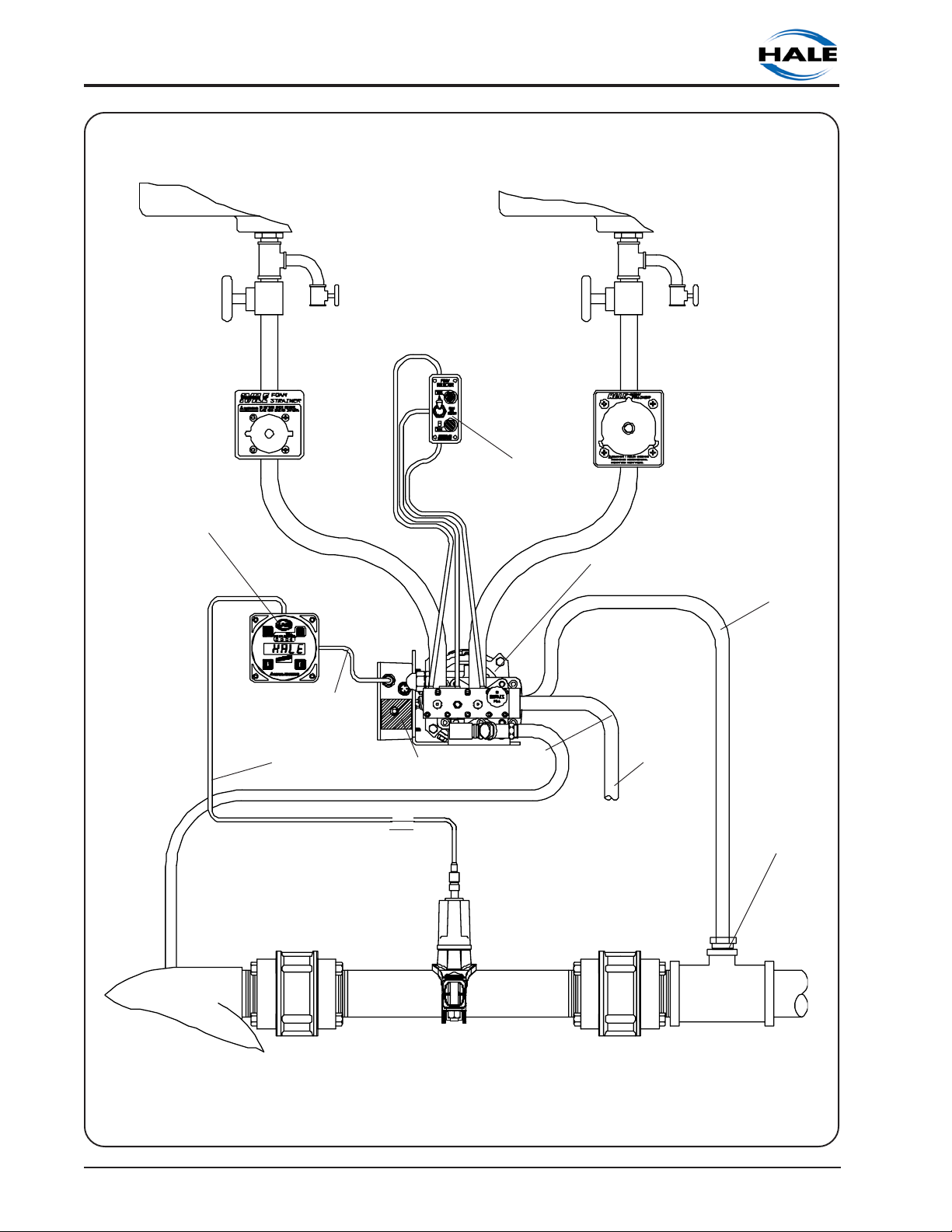
IN-LINE FOAM STRAINER/
VALVE ASSEMBLY
ROTARY GEAR PUMP
ELECTRONIC FOAM PROPORTIONING SYSTEM
FOAM
TANK A
FOAM
FOAM TANK
DRAIN
VALVE
ADT
SELECTOR
SWITCH AND
INDICATOR
LIGHTS
IN-LINE FOAM STRAINER/
VALVE ASSEMBLY
TANK B
FOAM TANK
DRAIN
VALVE
FLOWSENSOR
CORDSET
FLUSHING
WATER SUPPLY
FIRE
PUMP
CONTROL
UNIT
CONTROL
CORDSET
DISTRIBUTION
WATERWAY
CHECK
VALVE
BOX
FOAM PUMP
WITH ADT
BYPASS
VALVE
HALE
FLOWSENSOR
PADDLE WHEEL
MOUNTED IN
SADDLECLAMP
WATERWAY
BYPASS
CHECK
VALVE
FOAM
INJECTION
HOSE
CHECK VALVE
INJECTOR FITTING
HOSE
FOAM SOLUTION
DISCHARGE(S)
Figure 1-6. Hale Foam System Layout with Dual Foam Concentrate Tanks, ADT and In-
line Strainer/Valve Assemblies
Section I: Description
Ι-21
ROTARY GEAR PUMP
ELECTRONIC FOAM PROPORTIONING SYSTEM
FOAM TANK
SHUTOFF
VALVE
CONTROL
UNIT
FOAM
TANK A
FOAM TANK
DRAIN
VALVE
FS-15 PANEL
MOUNTED FOAM
STRAINER
FOAM
TANK B
FOAM TANK
SHUTOFF
VALVE
ADT
SELECTOR
SWITCH AND
INDICATOR
LIGHTS
FOAM PUMP
WITH ADT
FOAM TANK
DRAIN
VALVE
FS-25 PANEL
MOUNTED FOAM
STRAINER
FOAM
INJECTION
HOSE
FLOWSENSOR
CORDSET
FLUSHING
WATER SUPPLY
FIRE
PUMP
CONTROL
CORDSET
DISTRIBUTION
BOX
HALE
FLOWSENSOR
PADDLE WHEEL
MOUNTED IN
SADDLECLAMP
WATERWAY
CHECK
VALVE
BYPASS
VALVE
BYPASS
HOSE
WATERWAY
CHECK
VALVE
CHECK VALVE
INJECTOR
FITTING
FOAM SOLUTION
DISCHARGE(S)
Figure 1-7. Hale Foam System Layout with Dual Foam Concentrate Tanks, ADT and FS
Series Strainer Assemblies
Ι−22
Section I: Description

TM
FoamLogix
MODEL 3.3 AND 5.0 ROTARY GEAR
PUMP ELECTRONIC FOAM
PROPORTIONING SYSTEM
DESCRIPTION, INSTALLATION AND
OPERATION MANUAL
SECTION II
INSTALLATION
NOTICE: This manual section provides information to assist the OEM with installation and initial setup of Hale foam proportioning systems on an apparatus. This manual section can be used as a
stand alone section or in conjunction with other sections of the complete manual.
HALE PRODUCTS, INC. l A Unit of IDEX Corporation l 700 Spring Mill Avenue l Conshohocken, PA 19428 l TEL: 610-825-6300 l FAX: 610-825-6440
Hale Products cannot assume responsibility for product failure resulting from improper
maintenance or operation. Hale Products is responsible only to the limits stated in the product
warranty. Product specifications contained in this material are subject to change without notice.


ROTARY GEAR PUMP
ELECTRONIC FOAM PROPORTIONING SYSTEM
SAFETY
Hale FoamLogix systems are designed to provide reliable and safe foam concentrate
injection. Before installing or operating a Hale FoamLogix system read all safety
precautions and follow carefully to ensure proper installation and personnel safety.
WARNINGS
1. Do not permanently remove or alter any
guard or insulating devices or attempt to
operate the system when these guards
are temporarily removed.
2. To prevent electrical shock always
disconnect the primary power source
before attempting to service any part of
the Hale Foam system.
3. All electrical systems have the potential
to cause sparks during service. Take
care to eliminate explosive or hazardous
environments during service/repair.
4. To prevent system damage or electrical
shock the main power supply wire will be
the last connection made to the Hale
Foam proportioner distribution box.
5. Release all pressure then drain all
concentrate and water from the system
before servicing any of its component
parts.
6. Rotating drive line components can
cause injury. When working on
components of the Hale Foam system
be careful of rotating components.
CAUTIONS
1. Foam tank low level sensors must be
utilized to protect the Hale Foam
proportioner from dry running. Failure to
use low level sensors with the Hale Foam
system will void warranty.
2. Do not operate system at pressures
higher than the maximum rated
pressure.
3. Use only pipe, hose, and fittings from the
foam pump outlet to the injector fitting,
which are rated at or above the
maximum pressure rating at which the
water pump system operates.
4. Hale Foam proportioning systems are
designed for use on negative ground
direct current electrical systems only.
5. Do not mount radio transmitter or
transmitter cables in direct or close
contact with the FoamLogix control unit.
6. Before connecting the cordsets and
wiring harnesses inspect the seal washer
in the female connector. If the seal
washer is missing or damaged, water
can enter the connector causing
corrosion of the pins and terminals
resulting in possible system failure.
7. Always disconnect the power cable,
ground straps, electrical wires and
control cables from the control unit or
other Hale Foam system equipment
before electric arc welding at any point
on the apparatus. Failure to do so could
result in a power surge through the unit
that could cause irreparable damage.
8. DO NOT connect the main power lead
to small leads that are supplying some
other device such as a light bar or siren.
The Hale FoamLogix Model 3.3 and
Model 5.0 require 60 AMP minimum
current.
9. When operating the Hale FoamLogix in
Simulated Flow mode an outlet for the
foam concentrate must be provided to
prevent excessive pressure buildup in
discharge piping or hoses.
10. Unless engaged in Class B foam
operations, the ADT toggle switch or
MDT II selector handle must be in the
TANK A or FLUSH position. If the toggle
switch or selector handle is in the FLUSH
position when the Hale Foam system
foam pump is started the foam pump
will only run for 20 seconds and shut
down.
11. Make sure the foam tank and foam
concentrate suction hoses are clean
before making final connection to foam
pump. If necessary flush tank and hoses
prior to making connection.
Section II: Installation
ΙΙ-1

ROTARY GEAR PUMP
ELECTRONIC FOAM PROPORTIONING SYSTEM
NOTES
1. Check all hoses for weak or worn
conditions after each use. Ensure that
all connections and fittings are tight and
secure.
2. Ensure that the electrical source of
power for the unit is a negative ground
DC system, of correct input voltage, with
a reserve minimum current available to
drive the system.
3. The in-line strainer/valve assembly is a
low pressure device and WILL NOT
withstand flushing water pressure. When
installing the in-line strainer in systems
equipped with Hale MDT ΙΙ or Hale MST
make sure the in-line strainer/valve
assembly is in the hose on the inlet side
of the valve. If the strainer will be
subject to flushing water pressure, use
Hale FS series strainers.
4. When determining the location of Hale
Foam system components keep in mind
piping runs, cable routing and other
interferences that will hinder or interfere
with proper system performance.
5. Always position the check valve/injector
fitting at a horizontal or higher angle to
allow water to drain away from the
fitting. This will avoid sediment deposits
or the formation of an ice plug.
6. The cordsets provided with each Hale
Foam system are 100% electrically
shielded assemblies. Never attempt to
shorten or lengthen the molded cables.
If necessary order longer or shorter
cordsets from Hale Products to suit the
particular installation.
7. The cordsets provided with each Hale
Foam system are indexed so they only
go in the correct receptacle and they
can only go in one way. When making
cordset connections DO NOT force
mismatched connections as damage
can result in improper system operation.
8. The system can only perform when the
electrical connections are sound, so
make sure each one is correct.
9. The cables shipped with each Hale
Foam system are 100% tested at the
10. There are no user serviceable parts
11. Use mounting hardware that is
12. When making wire splice connections
13. Before running wires from the low tank
14. ALWAYS connect the primary positive
15. Prevent corrosion of power and ground
16. Prevent possible short circuit by using the
factory with that unit. Improper
handling and forcing connections can
damage these cables which could result
in other system damage.
inside Hale Foam system electrical/
electronic components. Opening of
these components (distribution box,
control unit, foam discharge multiplexing
display unit) will void warranty.
compatible with all foam concentrates
to be used in the system. Use washers,
lockwashers and capscrews made of
brass or 300 series stainless steel.
make sure they are properly insulated
and sealed using an adhesive filled heat
shrink tubing.
switches to the A-B switch box make sure
the wire from Tank A is identified and
properly labeled.
power lead from the terminal block to
the master switch terminal or the positive
battery terminal using minimum 4 AWG
type SGX (SAE J1127) chemical resistant
battery cable and protect with wire
loom.
connections by sealing these
connections with silicone sealant
provided.
rubber boot provided to insulate the
primary power connection at the Hale
FoamLogix distribution box.
ΙΙ-2
Section II: Installation

ROTARY GEAR PUMP
ELECTRONIC FOAM PROPORTIONING SYSTEM
APPARATUS INSTALLATION PLANNING
Differences in apparatus plumbing and
foam system configuration make it
impractical to show exactly how each Hale
FoamLogix system is installed on a particular
apparatus. The information contained in
this section, however, will apply to most
situations and should be used when
designing and installing a Hale FoamLogix
system. System plumbing and electrical
diagrams are provided at the end of this
installation section to assist the apparatus
manufacturer with installation of the Hale
FoamLogix system.
The following subsections provide the
system installer with guidelines for a
complete system installation. Before
proceeding with system installation carefully
review the procedures that follow to ensure
the system is properly designed. The
subsection titled Installer Supplied
Component Recommendations lists those
components that have been tested with
Hale FoamLogix and provide the best
system performance. Use of the
recommended materials and specified
parts will ensure a virtually maintenance
free installation.
The Hale FoamLogix system is supplied with
six major components that must be located
on the apparatus. The major components
of the Hale FoamLogix system are:
Foam pump and motor assembly
Control unit
In-Line foam strainer/valve assembly
Instruction/system diagram placard
Flowsensor
Check valve injector fitting
Optional components to enhance system
installation and operation that require
mounting on the apparatus include:
FS15 or FS25 panel mounted foam
strainer
ADT operating switch and indicator lights
(ADT valve is an optional part of foam
pump)
Manual dual tank (MDT ΙΙ) selector valve
Manual single tank (MST) selector valve
Mini Manifold
Flanged elbows
Foam tank(s)
Remote activation switch
IMPORTANT: When determining the
locations of Hale FoamLogix
components being installed keep in
mind piping runs, cable routing and
other interferences that will hinder or
interfere with proper system
performance.
FOAM PUMP and MOTOR ASSEMBLY: Ideally
the foam pump and motor assembly should
be located in an area that is protected
from road debris and excessive heat
buildup. The foam system master power
switch and bypass valve are located on the
foam pump and motor assembly and
access to these controls must be provided.
It is recommended that the foam pump
and motor assembly be located in a
protected area but, foam concentrate
gravity feed requirements or apparatus
design limitations may necessitate locating
the foam pump and motor assembly on a
shelf in the apparatus pump house or
attached to the apparatus frame.
The foam pump and motor assembly should
be mounted below the discharge of the
foam tank(s) to provide for gravity feed to
the foam pump. The foam tank(s) must be
located where refilling can be easily done
with 5 gallon (19 liter) pails and other
methods suitable to the end user. Most
water tank manufacturers will build foam
tanks into the booster tank. When
specifying foam tank(s) make sure
provisions are made for installation of the
low tank level sensor as well as foam suction
Section II: Installation
ΙΙ-3

ROTARY GEAR PUMP
ELECTRONIC FOAM PROPORTIONING SYSTEM
connections, tank drainage and proper fill
openings per NFPA requirements.
FOAM CONCENTRATE STRAINER: Determine
a location on the apparatus to mount the
foam strainer.
CAUTION: The in-line strainer/valve
assembly is a low pressure device and
WILL NOT withstand flushing water
pressure. When installing the in-line
strainer in systems equipped with Hale
MDT ΙΙ or Hale MST make sure the in-line
strainer/valve assembly is in the hose on
the inlet side of the valve. If the strainer
will be subject to flushing water pressure,
use Hale FS series strainers.
Mount the in-line foam strainer/valve
assembly in the foam concentrate hose
from the foam tank to the foam pump
suction connection, ADT, MDT ΙΙ or MST.
When determining the strainer location
keep in mind the requirement for gravity
feed of foam concentrate to the foam
pump through the strainer and avoid air
traps in the hoses. Also, clearance must be
provided to allow removal of the bowl
assembly for cleaning the stainless steel
mesh, to make hose connections to the
strainer and for operation of the service
valve.
If panel mounted FS series strainers are
installed mount the strainer in the foam
concentrate hose that supplies
concentrate to the ADT, MDT ΙΙ or MST. The
FS series strainer may also be mounted in
the outlet hose of the MDT ΙΙ or MST. When
determining strainer location on the
operator panel keep in mind the
requirement for gravity feed of foam
concentrate to the foam pump through the
strainer and avoid air traps in the hoses.
Clearance must be provided behind the
panel to allow for hose connections to the
strainer. The installer must provide a strainer
service isolation valve in the foam
concentrate hose to prevent spillage during
service. An MST or MDT ΙΙ can serve this
purpose also.
CONTROL UNIT and INSTRUCTION/SYSTEM
DIAGRAM PLACARD: Determine a location
on the operator panel of the apparatus for
the control unit and instruction/system
diagram placard. These components must
be located at the main pump operator
position in close proximity to each other.
Consideration must be given for routing the
control cable from the control unit to the
distribution box on the foam pump and
motor assembly. If necessary, order longer
or shorter cable assemblies to suit the
location demands.
ΙΙ-4
Section II: Installation

ROTARY GEAR PUMP
ELECTRONIC FOAM PROPORTIONING SYSTEM
INSTALLER SUPPLIED COMPONENT
RECOMMENDATIONS
Due to the many differences in apparatus
configuration and apparatus design
requirements the Hale FoamLogix system
installer must supply components such as
mounting brackets, piping, hoses, fittings
and some electrical wiring. The following
guidelines are recommendations for
selection of these additional components
for a complete system installation. The
recommendations made reflect those
materials and components that have been
tested extensively with Hale FoamLogix
systems and provide proven reliable
performance.
FOAM CONCENTRATE SUCTION HOSE
The system installer must supply fittings and
hoses from the foam tank to the inlet of the
foam pump. All components selected will
transfer foam concentrate therefore they
must be compatible with the foam
concentrates being used in the system.
Hoses for Class A foam concentrates must
have minimum ¾ inch (19 mm) inside
diameter. Hoses for Class B foam
concentrates must have minimum 1 inch
(25 mm) inside diameter due to higher
viscosity of the concentrates. Certain types
of Class B AFFF-ARC or ATC concentrates
will require a 1-1/4 or 1-1/2 inch ID foam
concentrate supply line.
Hoses for the foam concentrate suction
that WILL NOT be subjected to high pressure
such as flushing water and foam
concentrate discharge must have a rating
of 23 in (584.2 mm) Hg vacuum and 50 PSI
(3 BAR) pressure or greater. These hoses
include the hose from the foam tank outlet
to strainer inlet; strainer outlet to foam
pump, ADT, MDT ΙΙ or MST inlet.
NFPA requires that foam concentrate
suction hose be clear to observe foam
concentrate flow during foam pump
operation.
RECOMMENDED COMPONENTS:
Hose: PVC, Kuriyama Kuri-Tec K7130
series
Fittings: Hose Barb Type; Brass, Stainless
Steel or Nylon
When foam concentrate suction hose will
be subject to flushing water pressure it must
be rated for 23 in (584.2 mm) Hg vacuum
and the maximum discharge pressure of the
fire pump [500 PSI (34 BAR) minimum].
These hoses include the hose from the
outlet of the MDT ΙΙ or MST to the foam
pump inlet.
RECOMMENDED COMPONENTS:
Hose: Aeroquip 2580 Series or Equivalent
Reinforced Hydraulic Hose.
Fittings: Brass or Stainless Steel Hose End
Crimp or Reusable Type (Aeroquip
412 Series or Equivalent)
A foam tank shut-off valve and drain valve
should be provided in the foam tank suction
hose to allow strainer service, tank drainage
and easier priming. These components are
subject to the same material characteristics
and pressure ratings as stated above.
When the In-line strainer/valve assembly
option is installed the shut-off valve is
included as an integral part of the assembly
and a separate valve is not required.
FOAM CONCENTRATE DISCHARGE HOSE
The system installer must supply fittings and
hoses from the foam pump inject
connection to the check valve/injector
fitting inlet. All components selected will
transfer foam concentrate therefore they
must be compatible with the foam
concentrates being used in the system.
Section II: Installation
ΙΙ-5

ROTARY GEAR PUMP
ELECTRONIC FOAM PROPORTIONING SYSTEM
The foam pump discharge port and check
valve injector fitting connection port have
½ inch NPT threads. Hoses and fittings of ½
inch (13 mm) minimum inside diameter
rated at 500 PSI (34 BAR) working pressure or
maximum discharge pressure of the fire
pump must be used. Fittings and hoses
must be compatible with all foam agents to
be used.
RECOMMENDED COMPONENTS:
Hose: Aeroquip 2580-10 or Equivalent
Reinforced Hydraulic Hose.
Fittings: Brass or Stainless Steel Hose End
Crimp or Reusable Type (Aeroquip
412-9-10 or Equivalent)
Although air brake tubing has been used for
foam concentrate discharge hose, it is not
as flexible as the hydraulic hose and readily
kinks during installation. Additionally, the air
brake tubing may not meet NFPA 500 PSI
(34 BAR) test requirements.
FOAM CONCENTRATE BYPASS HOSE
The foam concentrate bypass hose
connection has ½ inch NPT threads. Hoses
and fittings of ½ inch (13 mm) minimum
inside diameter should be used as bypass
hose. Since the bypass hose is used for
calibration and draining the system it will
not see high operating pressures, therefore,
a hose with a lower pressure rating than the
inject hose can be used. Fittings and hoses
used must be compatible with all foam
agents expected to be used. Use fittings
made of brass or 300 series stainless steel
compatible with all foam concentrates.
RECOMMENDED COMPONENTS:
Hose: Low Pressure Hydraulic Hose or Air
Brake Tubing
Fittings: Brass or Stainless Steel
The foam concentrate bypass hose should
be long enough to extend past the
apparatus running board making foam
pump setup and calibration simpler.
CHECK VALVES
Check valves must be installed on
apparatus with foam systems to prevent
contamination of the foam concentrate
with water and contamination of the fresh
water tank with foam. (Refer to figures 1-1
through 1-5) When a Hale FoamLogix foam
injection system and related components
are properly installed the required check
valves are integral parts of the component
parts.
NFPA standards require a check valve in
the foam concentrate injection line at the
injection point. The Hale P/N 038-1790-00-0
Integral Check Valve/Injector fitting, a
standard component included with the
Hale FoamLogix system, meets these
requirements and threads directly into the
foam injection port on Hale manifolds.
Check valves must be installed in all water
piping locations where foam concentrate
could drain back into pumps or other
components of the fire apparatus. As a
minimum one check valve must be installed
where the water piping that will supply
foam solution connects to the fire pump
discharge. To more effectively keep foam
contamination out of the fire pump and
water tank double check valves should be
used. Separate two check valves by at
least 8 inches (203 mm) of piping to form a
dead zone between the check valves.
Individual drain lines should be used on
each check valve. The waterway check
valves must be rated for 500 PSIG (34 BAR)
working pressure.
Hale 3 inch "115" flange type check valves
(Hale P/N 038-1570-00-0) can be used for
most installations on pumps with "115" style
flanges. The Hale "115" flange type check
valve has a 4standard Hale "115" flanges as well as 4-
3
/8 inch bolt circle that fits
3
/8
inch bolt circle discharge flanges on other
pumps. These check valves are rated for
pressures up to 500 PSI (34 BAR) and flows
up to 750 GPM (2839 LPM). Use 2-½ or 3
inch NPT threaded "115" flanges for
mounting these check valves in piping runs.
ΙΙ-6
Section II: Installation

ELECTRONIC FOAM PROPORTIONING SYSTEM
Some installations may require higher flows
and larger diameter piping. Use a Hale 4
inch 2433 flange type check valve (Hale
P/N 038-1570-04-0) for these installations.
This check valve has an 8 bolt, 5-¾ inch bolt
circle and will fit pump discharge openings
and flanges that have this configuration.
The Hale 2433 check valve has a pressure
rating of 500 PSI (34 BAR) and a flow rating
of 1250 GPM (4731 LPM). The Hale 2433
style flange (Hale P/N 115-0040-00-0) has an
8 bolt, 5-¾ inch bolt circle and 4 inch NPT
threads for in-line mounting of the 4 inch
check valve.
FLUSHING WATER HOSE
Flush water connections for the Hale ADT,
Hale MDT ΙΙ or Hale MST must be made
using ½ inch inside diameter tubing and
appropriate fittings. The tubing and fittings
used must be capable of withstanding the
maximum fire pump discharge pressure (500
PSI (34 BAR) minimum) and should be
compatible with foam concentrates being
used in the system.
When the Hale ADT, Hale MDT ΙΙ or Hale MST
is installed a check valve is provided
integral to the flushing water line
connection to provide protection against
contamination of the water system with
foam concentrate.
Hale recommends the use of one of the
above selector options to provide foam
system flushing capabilities, but if the Hale
FoamLogix system is ordered with the "no
tank" option the system installer must
provide proper hose, shutoff valve, check
valves and connections for flushing water
for the system to be NFPA compliant.
Additionally, when the Hale FoamLogix is
installed without a Hale provided selector
some operating and system protection
features will not be available.
FOAM DISCHARGE DRAINS
Drains must be provided from foam
capable discharge piping components to
ROTARY GEAR PUMP
prevent freezing in cold weather. When
designing the drain system care must be
taken to prevent contamination of the
water system with foam and the foam
concentrate with water. Some multiple
drain systems that allow individual drain
lines to communicate also allow foam to
bypass the installed check valves causing
contamination of fire pump and the water
or foam concentrate storage tanks.
Hale has an optional 6 port drain valve,
Model MMD6 (Hale P/N 104961) that
provides individual drains with a single
control to use for applications where a
single point for multiple drains is required. If
a Hale MMD6 drain valve is not used then
individual drain lines and valves for foam
capable discharge piping are
recommended.
ELECTRICAL REQUIREMENTS
The system installer must provide the primary
power wire and a ground strap for the Hale
FoamLogix system.
Primary power must be supplied from the
main apparatus battery to the distribution
box on the foam pump and motor
assembly. The Hale FoamLogix Model 5.0
and Model 3.3 each require minimum 60
AMP electrical service.
Primary electrical power must be supplied
directly from the battery or the battery
master disconnect switch or solenoids to the
Hale FoamLogix. Other electrical
components must not be supplied from this
wire. DO NOT connect the primer and Hale
FoamLogix to the same power wire.
The toggle switch on the Hale FoamLogix
distribution box should be left in the ON
position at all times. So the Hale FoamLogix
system is ready for immediate operation
when the operator places the apparatus in
pump mode, and to prevent battery power
drain when the apparatus is not running,
the primary power connection must be
made so power is supplied to the Hale
Section II: Installation
ΙΙ-7
ROTARY GEAR PUMP
ELECTRONIC FOAM PROPORTIONING SYSTEM
FoamLogix when the main apparatus
electrical system is energized and the pump
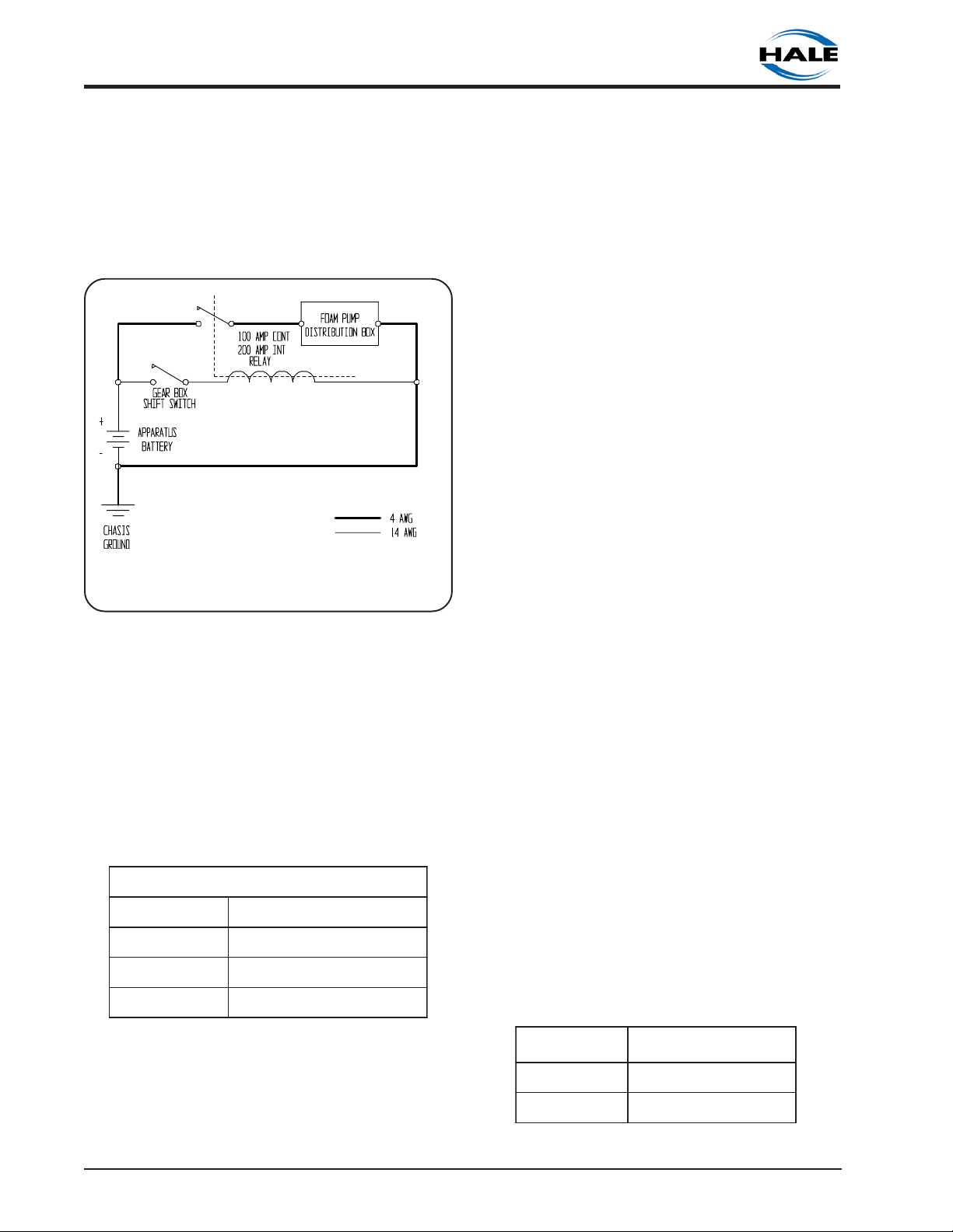
is in gear. Use of a solenoid with a 200 AMP
peak, 100 AMP continuous rating is
recommended. Figure 2-1 shows the
recommended wiring of this relay.
Figure 2-1. Recommended Relay Wiring
Schematic
equipment. The ground strap should be a
minimum of 1-¼ inches (32 mm) wide and
be no longer than 18 inches (457 mm). The
ground strap must have soldered flat lug
ends with 5/16 inch (8 mm) diameter holes.
If the ground strap length exceeds 18
inches (457 mm), a wider ground strap
should be used or use a double thickness of
1-¼ inches (32 mm) wide ground strap.
When making the ground strap connection
make sure the connection is made to the
chassis. Use minimum 5/16 inch (8 mm)
diameter bolt or mounting stud for this
connection.
Make sure the ground is attached directly
to the chassis frame and not to the
apparatus body work. Before making
ground connection remove all paint,
grease and coatings from the connection
area. After making connection seal against
corrosion. When a flat ground strap is not
available use a battery cable one size
larger than the power cable used.
With Hale FoamLogix Model 5.0 or Model
3.3, cable lengths up to 6 feet (1.8 meters)
require minimum 4 AWG type SGX (SAE
J1127) battery cable. Use solder lugs on
cable ends with a 5/16 inch (8 mm)
diameter hole. Refer to the following table
for the recommended battery cable size.
When planning cable runs make sure the
primary wires are routed by the shortest
most direct route.
SEZISELBACREWOPYRAMIRPDEDNEMMOCER
0.5&3.3sledoMhtgneLmumixaM
2
mm2.12(GWA4
)sseLro)M8.1(tF6
2
mm5.35(GWA0
))M6.4(tF51ot)M8.1(tF6
2
mm5.76(GWA00
)regnoLro)M6.4(tF51
A braided flat ground strap connected to
the apparatus chassis is recommended for
the ground connection to limit the RFI/EMI
interference encountered with radios,
computers or other sensitive electronic
NOTE: When an inline current shunt
ammeter is installed on the apparatus it is
necessary to install a power filter kit (Hale P/
N 546-1870-00-0) on the Hale FoamLogix
foam pump.
FOAM CONCENTRATE TANK(s)
Foam concentrate tank(s) must be supplied
to suit the capacity required for the
apparatus application. The tank(s) must
meet NFPA minimum standards for their
design capacity, including filler size, vapor
pressure venting, baffling and drain
facilities. The following table lists
recommended foam tank capacities for
the different Hale FoamLogix models based
on NFPA requirements for flammable liquid
(Class B) fire suppression.
RETSAMMAOF
LEDOM
0.5LEDOM)sretiL973(.LAG001
3.3LEDOM)sretiL052(.LAG66
MAOFDEDNEMMOCER
YTICAPACKNAT
ΙΙ-8
Section II: Installation

ELECTRONIC FOAM PROPORTIONING SYSTEM
FOAM PUMP MOUNTING
Position the foam pump and motor
assembly in the desired location on the
apparatus. When installing the foam pump
and motor assembly, the assembly should
be kept in a
base plate on the bottom (see figure 2-2).
Although the system is sealed and designed
to be resistant to the harsh environment of
fire fighting apparatus, a compartment with
easy operator access is the recommended
installation location.
The base plate of the foam pump and
motor assembly must be anchored to a
surface or structure that is rigid and of
adequate strength to withstand the
vibration and stresses of apparatus
operation. Figures 2-3 and 2-4 provide the
mounting envelope dimensions for the Hale
FoamLogix foam pump and motor
assembly.
horizontal position with the
ROTARY GEAR PUMP
CORRECT
INCORRECT
Position the foam pump so the ON/OFF
switch and bypass valve are easily
accessible. When the Hale FoamLogix
system is ordered without the ADT option, a
separate bypass valve is included that may
be removed from the foam pump and
mounted on a truck panel for easier
access. When the Hale FoamLogix system is
ordered with the ADT option, the operating
knob can be removed from the bypass
valve actuator and an extension rod can
be installed to permit remote operation. In
either instance the foam pump and motor
assembly must be located to permit proper
operation of the bypass valve.
Make sure the foam concentrate hoses can
be properly routed to the inlet and outlet on
the foam pump. Foam concentrate must
gravity feed to the foam pump inlet from
the foam tank(s). The foam pump must be
mounted in an area to avoid excessive
engine exhaust system or accessory heat
buildup.
INCORRECT
Figure 2-2. Hale FoamLogix Installation
The base of the foam pump and motor
assembly has predrilled mounting holes.
These holes will accept 5/16 inch (8 mm)
diameter bolts and the apparatus mounting
location needs to be drilled accordingly.
The base plate can be used as a template
to mark mounting hole location or a
mounting hole layout drawing is provided
as figure 2-5.
Section II: Installation
ΙΙ-9

ROTARY GEAR PUMP
ELECTRONIC FOAM PROPORTIONING SYSTEM
MODEL 5.0: 22.00 IN. (559 MM)
MODEL 3.3: 21.75 IN. (552 MM)
MODEL 5.0: 19.07 IN. (484 MM)
MODEL 3.3: 18.82 IN. (478 MM)
6.02 IN.
(153 MM)
9.43 IN.
(240 MM)
¾ INCH NPT SUCTION
HOSE CONNECTION
½ INCH NPT INJECT
HOSE CONNECTION
2.58 IN.
(66 MM)
½ INCH NPT BYPASS HOSE
CONNECTION
Figure 2-3. Hale FoamLogix Installation Envelope Dimensions
ΙΙ-10
Section II: Installation

ROTARY GEAR PUMP
ELECTRONIC FOAM PROPORTIONING SYSTEM
6.02 IN.
(153 MM)
TANK A CONNECTION
¾ INCH I.D. HOSE
6.20 IN.
(157 MM)
3.70 IN.
(94 MM)
MODEL 5.0: 25.37 IN. (644 MM)
MODEL 3.3: 25.12 IN. (638 MM)
MODEL 5.0: 24.74 IN. (628 MM)
MODEL 3.3: 24.94 IN. (622 MM)
MODEL 5.0: 23.70 IN. (602 MM)
MODEL 3.3: 23.45 IN. (596 MM)
MODEL 5.0: 21.88 IN. (555 MM)
MODEL 3.3: 21.63 IN. (549 MM)
MODEL 5.0: 20.63 IN. (524 MM)
MODEL 3.3: 20.38 IN. (518 MM)
MODEL 5.0: 19.07 IN. (484 MM)
MODEL 3.3: 18.82 IN. (478 MM)
8.95 IN.
(227 MM)
BYPASS HANDLE: BYPASS POSITION
BYPASS HANDLE: INJECT POSITION
INJECT PORT: ½ INCH NPT
BYPASS PORT: ½ INCH NPT
TO CENTER OF FLUSH
WATER INLET CONNECTION
TANK B CONNECTION
1 INCH I.D. HOSE
3.02 IN.
(77 MM)
0.87 IN. (22 MM)
4.76 IN.
(121 MM)
FLUSH WATER CONNECTION
½ INCH NPT
Figure 2-4. Hale FoamLogix Installation Envelope Dimensions with Optional ADT
0.81 IN.
(21 MM)
6.62 IN.
(168 MM)
4.81 IN.
(122 MM)
0.38 IN. (10 MM)
0.75 IN.
(19 MM)
14.06 IN.
(357 MM)
15.56 IN.
(395 MM)
DIA. THRU HOLE
(4 PLACES)
Figure 2-5. Hale FoamLogix Foam Pump and Motor Assembly Base Plate Dimensions
and Mounting Hole Locations
Section II: Installation
ΙΙ-11

ROTARY GEAR PUMP
ELECTRONIC FOAM PROPORTIONING SYSTEM
PLUMBING COMPONENT INSTALLATION
Hale FoamLogix System plumbing diagrams are located at the end of this manual section.
The diagrams provide recommended guidelines for the installation of system components
that handle water, foam concentrate and foam solution. The sequence in which the
plumbing installation is completed depends on the individual installation.
WATER AND FOAM SOLUTION
PLUMBING
When making water and foam solution
piping runs use the best industry practices to
install this piping. When making threaded
pipe connections use a suitable pipe
sealing compound at all joints.
OPTIONAL HALE PIPING COMPONENTS
Hale piping components such as 3 inch and
4 inch wafer type check valves, 115 and
2433 series flanges, mini manifold, etc. can
simplify installation of water and foam
solution discharge piping. The arrangement
shown in figure 2-6 provides accurate
MINIMUM LENGTH OF NIPPLE FOR
2-½ INCH PIPE AS SHOWN IS 12-½
INCHES (318 MM).
HALE 2H-98H ELBOW
("115" Flange x 2-½ INCH FNPT)
HALE HPF 25
FLOWSENSOR
proportioning across a wide range for up to
four discharges from the mini manifold. The
dual check valve arrangement helps to
ensure that no foam concentrate will
contaminate the pump water. The Hale
mini manifold provides a 1 inch NPT tap for
installation of the check valve/injector
fitting. The Hale mini manifold and elbow
components use 4-3/8 inch diameter bolt
circles and minimize fabrication and pipe
work. After installation of the plumbing is
complete make sure all pipes, hoses and
tubes are supported using the best industry
practices.
CHECK VALVE
INJECTOR FITTING
HALE 115 2-½
INCH NPT FLANGE
HALE MINI MANIFOLD
PROVIDES FOUR SEPARATE
DISCHARGE OUTLETS.
HALE "115" FLANGES ARE
AVAILABLE IN 1-¼ TO 3
INCH FNPT SIZES.
HALE 115 WAFER
TYPE CHECK
VALVE
ΙΙ-12
(Shown with optional machining that provides 2 additional
HALE MIDSHIP FIRE PUMP
Hale 115 flanged openings on top of the pump body)
Figure 2-6. Typical Midship Pump Installation
HALE 115
WAFER TYPE
CHECK VALVE
SUPPORT BRACKET FOR
HALE MINI MANIFOLD
(MANUFACTURED BY
SYSTEM INSTALLER)
Section II: Installation

ROTARY GEAR PUMP
ELECTRONIC FOAM PROPORTIONING SYSTEM
Figure 2-7 shows a suggested installation
arrangement using Hale 4 inch check
valves, Hale 2433 flanges and 4 inch pipe.
WATERWAY CHECK VALVES
Check valves in the waterway, rated at 500
PSI (34 BAR), are required to keep foam
solution out of the main pump and allow
pump priming without drawing foam into
the piping. Using double check valves,
separated by at least 8 inches (203 mm) of
pipe before the foam injection point, helps
ensure that pump and tank water remain
uncontaminated.
FLOWSENSOR
Hale FoamLogix flowsensor is specially
designed to make inspection and
maintenance of the flow sensor easy. The
flowsensor paddlewheel is installed on a
saddle clamp or weld fitting on the foam
capable discharge piping of the
apparatus. In horizontal piping runs, the
flowsensor should be mounted as close to
upright as possible within the range shown
in figure 2-8. DO NOT let the flowsensors
rotate more than 85o in either direction for
proper operation.
When selecting flowsensor it is important to
consider the minimum and maximum flow
requirements during operation. Refer to the
flowsensor selection chart in Section Ι of this
manual for proper pipe size for flow range
desired.
The flowsensor is installed in the piping
before the foam concentrate injection
point.
Some applications may require flowsensor
accuracy that is not within the range
specified for the discharge piping. This is
true in applications where the foam system
needs to supply a 3 inch deck gun as well
as a 1 inch booster line. Since the flow
through the deck gun will exceed the
capacity of the foam pump, pipe size for
flowsensor mounting should be selected to
provide accuracy at the lower flows.
Mounting the flowsensor in a short section of
pipe one pipe size smaller (4 inch to 3 inch,
3 inch to 2-½ inch, 2-½ inch to 2 inch or 2
inch to 1-½ inch) provides better accuracy
at the lower flows. Refer to the flowsensor
selection chart in Section Ι of this manual for
pipe size. Selection of the next smaller pipe
permits reducing the straight pipe run the
required distance prior to the flowsensor
paddlewheel then increasing the pipe size
Figure 2-7. Typical 4 Inch Check Valve Installation on Midship Pump
Section II: Installation
ΙΙ-13

ROTARY GEAR PUMP
ELECTRONIC FOAM PROPORTIONING SYSTEM
on the flowsensor outlet. In the short length
of reduced pipe pressure loss will be
minimal and there will be minimal pressure
loss through elbows and fittings. Figure 2-9
shows a typical reduced piping run
installation.
Excessive turbulence in the flowsensor may
produce unstable and inaccurate flow
readings. The length of straight pipe prior to
the flowsensor must be sufficient to reduce
the turbulence in the pipe. The following
installation guidelines will help attain the
best readings, and maintain the accuracy
of the Hale FoamLogix system.
a. A minimum 6 times the pipe diameter
of straight run pipe without any fittings is
necessary prior to the flowsensor
paddlewheel (see figure 2-10). Minimum
required straight pipe run:
eziSepiP
)mm83(.ni½-1)mm191(.ni9
)mm05(.ni2)mm452(.ni21
)mm46(.ni½-2)mm713(.ni51
)mm67(.ni3)mm183(.ni81
)mm201(.ni4)mm805(.ni42
dednemmoceRmuminiM
epiPnuRthgiartS
b. The downstream piping length is not
as critical but there should be a short
length of straight pipe with no fittings or
valves immediately after the flowsensor
paddlewheel.
c. Do not mount a flowsensor directly
after an elbow or valve. Valves create
severe turbulence when they are
“gated”.
Figure 2-8. Flowsensor Tee Position Range
in Horizontal Piping Runs
2-½ INCH X 2 INCH
NPT REDUCER
HALE 2H98 ELBOW
2-½ INCH NPT
OUTLET
HALE 3 INCH
CHECK VALVE
MIDSHIP PUMP
CONNECTION
SADDLE CLAMP INSTALLATION
Installation of the Paddlewheel Flowsensor
using a saddle clamp requires a 1.385/1.390
inch bored hole in the pipe. A minimum of
six times the pipe diameter of straight run
pipe without any fittings is necessary prior to
the position of the hole.
2 INCH DIAMETER
PIPE NIPPLE
2-½ INCH X 2 INCH
NPT REDUCER
2-½ INCH
DIAMETER PIPE
HALE HPF 20
FLOWSENSOR
MINIMUM 10 INCHES LONG
2 INCH DIAMETER PIPE
NIPPLE
2-½ INCH NPT
CLOSE NIPPLE
ΙΙ-14
Figure 2-9. Typical Reduced Flowsensor Piping Arrangement
Section II: Installation

ROTARY GEAR PUMP
ELECTRONIC FOAM PROPORTIONING SYSTEM
either direction for proper operation.
CORRECT
WATER
INLET
AT LEAST 5X THE PIPE
DIAMETER BETWEEN
VALVE OR FITTING AND
FLOWSENSOR
VALVE OR
FITTING AFTER
FLOWSENSOR
INCORRECT
WATER
INLET
Figure 2-10. Flowsensor Placement
For proper installation, the flowsensor
requires the use of a spacer and eight
stainless steel internal hex head screws.
Four 6 – 32 x ½ inch screws attach the
spacer to the saddle clamp mount, and
four 6 – 32 x ¾ inch screws with lockwashers
attach the paddlewheel to the spacer.
Align the spacer to the saddle clamp
mount by arranging the indexing pin of the
saddle clamp with the indexing hole of the
spacer. Use four ½ inch machine screws
without lockwashers to secure the two
pieces. Torque to 8.5 inch pounds.
Align the paddlewheel indexing pin to the
indexing hole in the spacer, secure using
four ¾ inch screws and lockwashers.
Torque to 7.5 inch pounds.
VALVE OR FITTING BEFORE
FLOWSENSOR WITH LESS THAN 5X
THE PIPE DIAMETER BETWEEN
FOAM PUMP FLUSH SYSTEM
When dual foam tanks are installed on the
apparatus, flushing water must be provided
to flush the system of foam concentrate
after use of some foam concentrate types
to prevent possible reactions. The Hale ADT
and Hale MDT II each have provisions for
connecting flushing water to the foam
concentrate injection system.
If a single foam concentrate tank system is
installed on the apparatus the Hale MST
provides a selector valve and gives the
system flush capabilities for NFPA
compliance. A fitting provided on the Hale
MST makes connection of flushing water
simple.
When the Hale FoamLogix is installed with
the "no tank" option the system installer must
provide flushing water supply to comply
with NFPA standards.
Flushing water hose should have a minimum
of ½ inch (12 mm) inside diameter and be
capable of withstanding the maximum fire
pump discharge pressure, 500 PSI (34 BAR)
minimum. The flush water supply should be
provided from one of the pressure taps on
the discharge of the fire pump. It is
recommended that a check valve be
installed at the pressure tap to prevent
contamination. Flush water thread
connections on the ADT are ½ inch NPT and
on the Hale MDT ΙΙ and Hale MST they are ¼
inch NPT. The system installer must provide
proper fittings for these connections.
Apply a small amount of grease to the
saddle clamp gasket before the final
installation of the assembly onto the pipe.
Tighten the saddle clamp onto the pipe
firmly.
The paddlewheel should be installed as
close to upright as possible within the range
shown in figure 2-8. Do not let the
flowsensor rotate more than 85 degrees in
Section II: Installation
FOAM CONCENTRATE PLUMBING
Foam concentrate plumbing consists of the
foam concentrate suction hose, foam
strainer, foam concentrate discharge hose
and check valve/injector fitting.
CAUTION: Make sure the foam tank and
foam concentrate suction hoses are
clean before making final connection to
foam pump. Flush tank and hoses prior
ΙΙ-15

ROTARY GEAR PUMP
ELECTRONIC FOAM PROPORTIONING SYSTEM
1 inch (25 mm) or 1-1/4 inch (32 mm) inside
SENSOR
O-RINGS
diameter hose depending on the viscosity
of foam concentrates used. (See figure 2-
12) Generally ¾ inch inside diameter hose
will be used for Class A foam and 1 inch
inside diameter hose will be used for Class B
foams. For high viscosity Class B foam
concentrates it may be necessary to use 11/4 or 1-1/2 inside diameter hose. A
bracket is included with the in-line strainer/
valve assembly to permit installation on the
apparatus.
SADDLE CLAMP
WATER FLOW DIRECTION
Figure 2-11. Flowsensor Sensor Service
to making connections.
NOTE: Foam concentrate gravity fed.
FOAM STRAINER
IN-LINE STRAINER/VALVE ASSEMBLY
CAUTION: The in-line strainer/valve
assembly is a low pressure device and
WILL NOT withstand flushing water
pressure. When installing the in-line
strainer in systems equipped with Hale
MDT ΙΙ or Hale MST make sure the in-line
strainer/valve assembly is in the hose on
the inlet side of the valve. If the strainer
will be subject to flushing water pressure,
use Hale FS series strainers.
The in-line strainer/valve assembly has 1-1/4
inch NPT female threaded ports. Fittings are
supplied for connection of ¾ inch (19 mm),
The hose from the foam tank(s) to the
strainer should have adequate wall stiffness
to withstand the vacuum of the foam pump
while it is operating [23 inches (584 mm) Hg
and 50 PSI (3 BAR)] (Kuriyama, Kuri-tec K7130 series or equal).
The following procedures are provided for
installation of the in-line strainer/valve
assembly:
1. Choose a location on the apparatus
that allows gravity feed from the foam
tank to the strainer inlet and from the
strainer outlet to the foam pump suction
connection.
NOTE: When selecting the strainer
location make sure there is sufficient
space below the strainer for removal of
the strainer basket and screen for
cleaning. A minimum of 5 inches (127
mm) is required for this purpose. Also
make sure there is at least 2 inches (51
mm) above the strainer assembly to
permit operation of the service valve.
(Refer to figure 2-12)
2. Refer to the diagram in figure 2-13 and
mark 4 holes for mounting the foam
strainer bracket. The holes must be
drilled to accommodate ¼-20 UNC
screws. The holes can either be tapped
(#7 drill for ¼-20 UNC tap) or drill large
enough to use screws, nuts and washers
(9/32 inch (7 mm) diameter) to secure
ΙΙ-16
Section II: Installation

ROTARY GEAR PUMP
ELECTRONIC FOAM PROPORTIONING SYSTEM
1-1/4 INCH NPT X 1-1/4
INCH HOSE BARB
(Use on each end for Class
B foam concentrates)
FOAM
CONCENTRATE
OUTLET
1-1/4 INCH NPT X 3/4 INCH
HOSE BARB
(Use on each end for Class
A foam concentrates)
5 INCHES (127 mm) MINIMUM
STRAINER
MOUNTING
BRACKET
CLEARANCE BELOW FOR
ELEMENT MAINTENANCE
Figure 2-12. In-Line Strainer/Valve Installation
the bracket to the apparatus. Secure
the bracket and strainer/valve assembly
to the apparatus.
2 INCHES (51 mm) MINIMUM
CLEARANCE ABOVE FOR
VALVE OPERATION
STRAINER SERVICE
VALVE
(Shown in open
position. Rotate 90
clockwise to close)
o
end. Wetting the ends of the hose and
fittings will make the installation on the
hose fittings easier.
FOAM
CONCENTRATE
INLET
1-1/4 INCH NPT X 1 INCH
HOSE BARB
(Use on each end for
Class B foam
concentrates)
3. Select the appropriate fittings from the
bag attached to the strainer assembly.
Two of each fitting are included with the
strainer assembly.
For Class A foam concentrate use the
supplied 1-1/4 inch NPT x ¾ inch hose
fittings in each end of the strainer/valve
assembly.
For most Class B foam concentrates use
the 1-1/4 inch NPT x 1 inch hose fittings.
When using higher viscosity Class B ATC
concentrates use the 1-1/4 inch NPT x 11/4 inch hose fittings
Before assembly coat all fitting threads
with Permatex #80724 (or equal) plastic
pipe thread sealant. Install the fittings
into the strainer/valve assembly ends
and tighten securely.
4. Install the clear plastic hose from the
foam tank outlet to the inlet of the
strainer/valve assembly. The inlet of the
strainer/valve assembly is on the valve
CAUTION: Make sure the foam tank and
foam concentrate suction hoses are
clean before making final connection to
foam pump. If necessary flush tank and
hoses prior to making connection.
5. Install the clear plastic hose from the inline strainer/valve assembly outlet to the
STRAINER BRACKET OUTLINE
SHOWN FOR CLARITY
2-21/32 IN.
(67 MM)
4 HOLES (#7 DRILL
IF TAPPED ¼-20
UNC or 9/32 IN (7
MM) DIAMETER
3-1/8 IN.
(79 MM)
Figure 2-13. In-Line Strainer Mounting
Bracket Hole Layout Dimensions
Section II: Installation
ΙΙ-17

ROTARY GEAR PUMP
ELECTRONIC FOAM PROPORTIONING SYSTEM
inlet of the Hale MDT ΙΙ, Hale MST or
foam concentrate pump or correct
fitting on Hale ADT.
FS SERIES STRAINER
When a pressurized water flush is provided
to the strainer from one of the discharges
the use of Hale FS series strainers is required.
The plumbing exposed to the flush water
pressure must be rated at or above the
operating pressure of all other discharge
plumbing components. [500 PSI (34 BAR)
minimum]
The following procedures are provided for
installation of FS series strainers:
Figure 2-14. FS Series Strainer Orientation
LOOKING FROM BACK OF STRAINER
NOTE: When selecting the strainer
location make sure there is sufficient
space behind the pump panel to permit
attaching hoses and fittings. Make sure
the inlet connection port is oriented as
shown in figure 2-14 when installing the
FS series strainer.
1. Choose a location on the apparatus
that allows gravity feed from the foam
tank to the strainer inlet and from the
strainer outlet to the foam pump suction
connection.
2.13 IN. (54 MM)
DIA. HOLE
4.28 IN.
(109 MM)
TYP.
0.28 IN. (7 MM)
DIA. THRU HOLE
(4 PLACES)
¾ INCH NPT
THREADED
OUTLET
1.00 IN.
(25 MM)
1.00 IN.
(25 MM)
2.14 IN.
(54 MM)
1-½ INCH
NST CAP
2. Remove the strainer cap, mounting
screws and nameplate from the strainer
assembly.
3. Using the nameplate as a guide, or refer
to the diagrams in figure 2-15, mark
3.00 IN.
(76 MM)
4.28 IN.
(109 MM)
3.38 IN. (86 MM)
DIA. HOLE
4.75 IN.
(121 MM)
2.38 IN.
(60 MM)
1 INCH NPT
THREADED
OUTLET
0.34 IN. (9 MM)
DIA. THRU HOLE
(4 PLACES)
1.50 IN.
(38 MM)
3.00 IN.
(76 MM)
2-½ INCH
NST CAP
1.50 IN.
(38 MM)
ΙΙ-18
0.88 IN.
(22 MM)
7.34 IN.
(186 MM)
FS15 STRAINER FS25 STRAINER
¾ INCH NPT
THREADED
INLET
OPERATOR
PANEL
1 INCH
NPT
THREADED
INLET
OPERATOR
1.13 IN.
(29 MM)
7.09 IN.
(180 MM)
PANEL
Figure 2-15. FS Series Strainer Mounting Dimensions
Section II: Installation

ROTARY GEAR PUMP
ELECTRONIC FOAM PROPORTIONING SYSTEM
holes for mounting the foam strainer.
The holes for the FS15 strainer mounting
screws are 9/32 inch (7 mm) and the
holes for FS25 strainer screws are 11/32
inch (9 mm) diameter. Additionally a
hole of sufficient size for the cap threads
to clear the panel is required. [FS15
strainer 2.13 inches (54 mm) and FS25
strainer 3.38 inches (86 mm)]
4. Select appropriate fittings for
attachment of the hoses to the strainer.
The fittings and hoses chosen must be
capable of withstanding the vacuum
generated by the foam pump [23
inches (584 mm) Hg] and the maximum
flushing water pressure [500 PSI (34
BAR)].
When using an FS15 strainer use ¾ inch
NPT x ¾ inch hose fittings.
When using an FS25 strainer use 1 inch
NPT x 1 inch hose fittings.
Before assembly coat all fitting threads
with a suitable thread sealant (Do not
use Teflon tape). Install the fittings into
the strainer and tighten securely.
7. Install the hose from the strainer outlet to
the inlet of the Hale FoamLogix foam
pump or selector valve.
CHECK VALVE/INJECTOR FITTING
The Hale check valve/injector fitting
supplied with the Hale FoamLogix system
meets NFPA requirements for a non-return
device in the foam injection system to
prevent back flow of water into the foam
concentrate tank. When properly installed
the brass and stainless steel construction
check valve/injector fitting ensures foam
concentrate is injected into the center of
the water flow for better mixing.
NOTE: Always position the check valve/
injector fitting at a horizontal or higher
angle to allow water to drain away from
the fitting (see figure 2-16). This will avoid
sediment deposits or the formation of an
ice plug.
CORRECT
CHECK VALVE/INJECTOR FITTING
ABOVE HORIZONTAL PLANE
INCORRECT
5. Make sure the strainer is oriented as
shown in figure 2-14 and secure the
strainer body and nameplate to the
apparatus with the screws provided.
Install the cap on the strainer.
6. Install the hose from the foam tank
outlet to the inlet of the strainer. The
inlet of the strainer is closer to the
operator panel and is oriented as shown
in figure 2-14. Wetting the ends of the
hose and fittings will help ease
installation on the hose fittings.
CAUTION: Make sure the foam tank and
foam concentrate suction hoses are
clean before making final connection to
foam pump. Flush tank and hoses prior
to making connection.
Section II: Installation
CHECK VALVE/INJECTOR FITTING
BELOW HORIZONTAL PLANE
Figure 2-16. Check Valve/Injector Fitting
Position
The check valve/injector fitting MUST be
mounted in a location that is common to all
discharges which require foam concentrate
(see figure 2-18). The Hale FoamLogix
system does not permit a separate injection
point for each foam capable discharge.
The check valve/injector fitting has 1 inch
NPT threads on the outside to fit into the 1
ΙΙ-19

ROTARY GEAR PUMP
ELECTRONIC FOAM PROPORTIONING SYSTEM
½ INCH NPT THREADS
(FOAM CONCENTRATE INLET)
CHECK VALVE
INJECTOR
FITTING
1 INCH NPT
THREADS
HALE MANIFOLD,
PIPE TEE OR
WELD BOSS ON
PIPE
Figure 2-17. Check Valve Injector Fitting
Installation
inch NPT threaded connection on the Hale
mini manifold, a pipe tee or a 1 inch NPT
weld fitting installed in the discharge piping
of the fire pump (see figure 2-17). The inlet
connection of the check valve/injector
fitting has ½ inch NPT female threads.
FOAM CONCENTRATE INJECTION HOSE
Connect hose from the foam pump inject
port (see figure 2-18) to the inlet of the
check valve injector fitting. The hose and
fittings from the INJECT port to the check
valve injector fitting should have minimum
½ inch (13 mm) inside diameter and be
rated at 500 PSI (34 BAR) working pressure
(Aeroquip 2580-10 or equal).
BYPASS HOSE CONNECTION
A bypass port is provided on the discharge
side of the Hale ADT or a 1/4 turn bypass
valve is mounted on the discharge of the
foam pump when the ADT option is not
installed. The bypass handle shall be
accessible by the pump operator during
normal operations.
The bypass valve is a 3-way directional
valve that selects where the output of the
foam pump will go. Determine which port is
the INJECT port (see figure 2-18) and which
port is the BYPASS port. The INJECT port is
identified on the bypass valve placard.
Look at the ports as you move the handle,
the flow should go from the center port to
each of the other ports. The bypass port on
the ADT is identified by a label above the
port.
Bypass hose connections are ½ inch NPT
threads. Hose fittings compatible with all
foam concentrates to be used must be
provided. The hose from the BYPASS port is
plumbed to the atmosphere and should not
receive high pressures. This hose is used for
calibrating the foam pump, pumping the
concentrate into a container to empty the
FOAM
CONCENTRATE
INLET
¾ INCH NPT
FOAM
PUMP
INJECT PORT
½ INCH NPT
BYPASS PORT
½ INCH NPT
BYPASS
VALVE
HALE FOAMLOGIX WITH NO TANK, MST
OR MDT ΙΙ OPTION
Figure 2-18. Injection and Bypass Hose Connections
ΙΙ-20
FOAM CONCENTRATE
INLET CONNECTION
BYPASS VALVE
HANDLE
BYPASS PORT
½ INCH NPT
FLUSHING WATER
PORT ½ INCH NPT
FOAM PUMP NOT
SHOWN FOR
CLARITY
INJECT PORT
½ INCH NPT
HALE FOAMLOGIX WITH ADT OPTION
Section II: Installation

ELECTRONIC FOAM PROPORTIONING SYSTEM
foam tank or to assist in priming of the foam
pump. The hose from the BYPASS port must
be long enough to reach a container
outside the truck. This hose must be coiled
for storage when not in use.
ROTARY GEAR PUMP
ACORN NUT
HANDLE
If the handle or placard is removed from
the bypass valve for repairs or to facilitate
remote mounting make sure they are
installed on the valve correctly. Make sure
the tang on the handle engages the cast
stops as shown in figure 2-9.
ADT AIR CONNECTIONS
If the ADT option is used, install the
operating switch and indicator light placard
for the ADT on the apparatus operator
panel. A mounting cutout diagram is
provided as figure 2-20.
After mounting the placard assembly install
the air hoses from the ADT to the placard
assembly. Make sure proper connections
are made at the placard assembly as
PLACARD OUTLINE SHOWN
FOR REFERENCE ONLY
1.69 IN.
(43 mm)
1.25 IN.
(32 mm)
HANDLE
TANG
PLACARD
PLACARD
SCREWS
CAST
BOSSES
INJECT HOSE
CONNECTION
BYPASS HOSE
CONNECTION
Figure 2-19. Bypass Valve Assembly
DRILL 4 THRU HOLES
7/32 IN. (6 mm) DIA.
3.50 IN.
(89 mm)
Figure 2-20. ADT Panel Placard Panel Cutout and Hole Dimensions
Section II: Installation
2.75 IN.
(70 mm)
1.38 IN.
(35 mm)
0.25 IN.
(6 mm)
RADIUS
TYP.
0.84 IN.
(21 mm)
1.63 IN.
(41 mm)
0.63 IN.
(16 mm)
ΙΙ-21

ROTARY GEAR PUMP
ELECTRONIC FOAM PROPORTIONING SYSTEM
indicated in figure 2-21. A color coded
decal attached to the ADT valve assembly
along with an optional color coded air hose
harness simplifies air hose connections. If
the optional air hose harness is not used ¼
inch inside diameter air brake tubing can
be substituted. Make sure the air brake
tubing selected has the proper DOT
approval. When cutting the air harness or
air brake tubing to size make sure the ends
are square using a tubing cutter or razor
knife.
ΙΙ-22
Section II: Installation

ROTARY GEAR PUMP
ELECTRONIC FOAM PROPORTIONING SYSTEM
AIR OUT A
(GREEN)
AIR IN
(BLACK)
TANK A
INDICATOR
SELECTOR
SWITCH
ELECTRICAL HARNESS
ADT PANEL PLACARD SIDE VIEW
TANK B
INDICATOR
AIR OUT B
(RED)
PANEL
PLACARD
ASSEMBLY
¼ INCH O.D. AIR
HOSE OR AIR
HARNESS
ASSEMBLY
AIR OUT
(BLACK)
TOP VIEW OF ADT ASSEMBLY
Section II: Installation
AIR IN B
(RED)
ADT ASSEMBLY
(FOAM PUMP NOT
SHOWN FOR CLARITY)
AIR SUPPLY FROM
APPARATUS AIR SYSTEM
AIR IN A
(GREEN)
Figure 2-21. ADT Air Hose Connections
ΙΙ-23

ROTARY GEAR PUMP
ELECTRONIC FOAM PROPORTIONING SYSTEM
SYSTEM PLUMBING DIAGRAMS
The following pages contain Hale FoamLogix system plumbing diagrams for the various
system configurations. Due to variations in apparatus configuration and individual
component locations, lengths of hoses and piping is not provided. The material described
and component sizes are those which will provide optimum performance of a Hale
FoamLogix system. These diagrams are intended as guidelines to assist the system installer
with selection of hoses and fittings along with the connections required.
ΙΙ-24
Section II: Installation

IMPORTANT: When Hale FoamLogix system is ordered
without a tank option the installer must provide the
fittings necessary for flushing the foam system to be
NFPA compliant. These components are:
Foam concentrate check valve; prevents water
contamination of foam tank and pressurization of inline strainer/valve assembly.
Tee; to connect flush water hose to foam concentrate
hose.
Flush Water Check Valve; prevents foam
contamination of water system.
Flush Water Shutoff Valve
¾ INCH NPT x ¾ INCH
HOSE FITTING
FOAM
CONCENTRATE
CHECK VALVE
FLUSH WATER
CHECK VALVE
ROTARY GEAR PUMP
ELECTRONIC FOAM PROPORTIONING SYSTEM
FOAM
TANK
FOAM TANK
DRAIN
VALVE
1 INCH NPT x ¾ INCH
NPT BUSHING
¾ INCH NPT x ¾ INCH
HOSE FITTING
FOAM SUCTION HOSE
¾ INCH (19 MM) INSIDE
DIAMETER CLEAR
RATED AT 23 INCHES
(584 mm) Hg VACUUM
and 50 PSI (3 BAR)
FLUSH WATER
VALVE
FOAM SUCTION HOSE
¾ INCH (19 MM) INSIDE
DIAMETER CLEAR
RATED AT 23 INCHES
(584 mm) Hg VACUUM
and 500 PSI (34 BAR)
FOAM PUMP AND
ASSEMBLY
FLUSH WATER SUPPLY HOSE
OR ½ INCH (10 or 12 MM)
OUTSIDE DIAMETER RATED AT
500 PSI (34 BAR)
TEE
MOTOR
3
/8
BYPASS
VALVE
IN-LINE FOAM STRAINER/
VALVE ASSEMBLY
FOAM INJECTION
HOSE ½ INCH (12 MM)
INSIDE DIAMETER
RATED FOR 500 PSI
(34 BAR) WITH ½
INCH NPT FITTINGS
BYPASS
HOSE
HALE
FLOWSENSOR
PADDLE WHEEL
MOUNTED IN
SADDLECLAMP
CHECK VALVE
INJECTOR
FITTING
FIRE
PUMP
WATERWAY
CHECK
VALVE
WATERWAY
CHECK
VALVE
Hale FoamLogix System Plumbing Diagram with Single Foam Concentrate Tank
Section II: Installation
FOAM SOLUTION
DISCHARGE(S)
ΙΙ-25

ROTARY GEAR PUMP
ELECTRONIC FOAM PROPORTIONING SYSTEM
FOAM
TANK
FOAM SUCTION HOSE
¾ INCH (19 MM) INSIDE
RATED AT 23 INCHES
(584 mm) Hg VACUUM
MST SELECTOR
¼ INCH NPT
FLUSH HOSE
CONNECTION
DIAMETER CLEAR
and 50 PSI (3 BAR)
¾ INCH NPT
FOAM HOSE
CONNECTIONS
FOAM SUCTION HOSE
¾ INCH (19 MM) INSIDE
DIAMETER RATED FOR
23 INCHES (584 mm)
Hg VACUUM and 500
PSI (34 BAR)
FOAM PUMP AND
MOTOR
ASSEMBLY
¾ INCH NPT x ¾ INCH
HOSE FITTING
1 INCH NPT x ¾ INCH
NPT BUSHING
¾ INCH NPT x ¾ INCH
HOSE FITTING
IN-LINE FOAM STRAINER/
VALVE ASSEMBLY
FOAM INJECTION
HOSE ½ INCH (12 MM)
INSIDE DIAMETER
RATED FOR 500 PSI
(34 BAR) WITH ½
INCH NPT FITTINGS
BYPASS
VALVE
FOAM TANK
DRAIN
VALVE
FOAM SUCTION HOSE
¾ INCH (19 MM) INSIDE
DIAMETER CLEAR
RATED AT 23 INCHES
(584 mm) Hg VACUUM
and 50 PSI (3 BAR)
FLUSH WATER SUPPLY HOSE
3
/8 OR ½ INCH (10 or 12 MM)
OUTSIDE DIAMETER RATED
AT 500 PSI (34 BAR)
FIRE
PUMP
WATERWAY
CHECK
VALVE
HALE
FLOWSENSOR
PADDLE WHEEL
MOUNTED IN
SADDLECLAMP
BYPASS HOSE
AIR BRAKE TUBING ½
INCH INSIDE DIAMETER
WATERWAY
CHECK
VALVE
CHECK VALVE
INJECTOR
FITTING
FOAM SOLUTION
DISCHARGE(S)
Hale FoamLogix System Plumbing Diagram with Single Foam Concentrate Tank, MST and
In-line Strainer/Valve Assembly
ΙΙ-26
Section II: Installation

ROTARY GEAR PUMP
ELECTRONIC FOAM PROPORTIONING SYSTEM
FOAM
TANK
FOAM SUCTION HOSE
¾ INCH (19 MM) INSIDE
RATED AT 23 INCHES
(584 mm) Hg VACUUM
¾ INCH NPT x ¾ INCH
HOSE FITTINGS FOR FS15
STRAINER
1 INCH NPT x ¾ INCH HOSE
FITTINGS FOR FS25
STRAINER
FOAM PUMP AND
MOTOR
ASSEMBLY
DIAMETER CLEAR
and 50 PSI (3 BAR)
¼ INCH NPT
FLUSH HOSE
CONNECTION
FOAM TANK
SHUTOFF
VALVE
FOAM INJECTION
HOSE ½ INCH (12 MM)
INSIDE DIAMETER
RATED FOR 500 PSI
(34 BAR) WITH ½
INCH NPT FITTINGS
BYPASS
VALVE
FOAM TANK
DRAIN
VALVE
MST SELECTOR
¾ INCH NPT
FOAM HOSE
CONNECTIONS
FOAM SUCTION HOSE
¾ INCH (19 MM) INSIDE
DIAMETER RATED FOR
23 INCHES (584 mm)
Hg VACUUM and 500
PSI (34 BAR)
FLUSH WATER SUPPLY HOSE
3
/8 OR ½ INCH (10 or 12 MM)
OUTSIDE DIAMETER RATED
AT 500 PSI (34 BAR)
FIRE
PUMP
WATERWAY
CHECK
VALVE
HALE
FLOWSENSOR
PADDLE WHEEL
MOUNTED IN
SADDLECLAMP
BYPASS
HOSE
WATERWAY
CHECK
VALVE
FOAM SOLUTION
DISCHARGE(S)
CHECK VALVE
INJECTOR
FITTING
Hale FoamLogix System Plumbing Diagram with Single Foam Concentrate Tank, MST and
FS Series Strainer
Section II: Installation
ΙΙ-27

ROTARY GEAR PUMP
ELECTRONIC FOAM PROPORTIONING SYSTEM
FOAM SUCTION HOSE
¾ INCH (19 MM) INSIDE
DIAMETER CLEAR
RATED AT 23 INCHES
(584 mm) Hg VACUUM
and 50 PSI (3 BAR)
1 INCH NPT x ¾ INCH
NPT BUSHING
TANK A
¾ INCH NPT x ¾ INCH
HOSE FITTING
FOAM
FOAM TANK
DRAIN
VALVE
1 INCH NPT x 1 INCH
MDT II SELECTOR ¾
INCH NPT FOAM
HOSE CONNECTIONS
HOSE FITTING
FOAM
TANK B
FOAM TANK
DRAIN
VALVE
FOAM SUCTION HOSE
1 INCH (25 MM) INSIDE
DIAMETER CLEAR
RATED AT 23 INCHES
(584 mm) Hg VACUUM
and 50 PSI (3 BAR)
FIRE
PUMP
¼ INCH NPT
FLUSH AND
DRAIN HOSE
CONNECTIONS
FOAM PUMP AND
MOTOR
ASSEMBLY
FLUSH WATER SUPPLY HOSE
3
/8 OR ½ INCH (10 or 12 MM)
OUTSIDE DIAMETER RATED
AT 500 PSI (34 BAR)
WATERWAY
CHECK
VALVE
PADDLE WHEEL
SADDLECLAMP
HALE
FLOWSENSOR
MOUNTED IN
FOAM SUCTION HOSE
¾ INCH (19 MM) INSIDE
DIAMETER RATED FOR
23 INCHES (584 mm)
Hg VACUUM and 500
PSI (34 BAR)
BYPASS
VALVE
BYPASS HOSE
AIR BRAKE TUBING ½
INCH INSIDE DIAMETER
WATERWAY
CHECK
VALVE
FOAM INJECTION
HOSE ½ INCH (12 MM)
INSIDE DIAMETER
RATED FOR 500 PSI
(34 BAR) WITH ½
INCH NPT FITTINGS
CHECK VALVE
INJECTOR
FITTING
FOAM SOLUTION
DISCHARGE(S)
Hale FoamLogix System Plumbing Diagram with Dual Foam Concentrate Tanks, MDT ΙΙ
and In-line Strainer/Valve Assembly
ΙΙ-28
Section II: Installation

ROTARY GEAR PUMP
ELECTRONIC FOAM PROPORTIONING SYSTEM
FOAM
TANK A
FOAM TANK
SHUTOFF
VALVE
FOAM SUCTION HOSE
¾ INCH (19 MM) INSIDE
DIAMETER CLEAR
RATED AT 23 INCHES
(584 mm) Hg VACUUM
and 50 PSI (3 BAR)
FOAM TANK
DRAIN
VALVE
¼ INCH NPT
FLUSH AND
DRAIN HOSE
CONNECTIONS
¾ INCH NPT x ¾ INCH
HOSE FITTINGS FOR FS15
1 INCH NPT x ¾ INCH HOSE
FLUSH WATER SUPPLY HOSE
3
/8 OR ½ INCH (10 or 12 MM)
OUTSIDE DIAMETER RATED
AT 500 PSI (34 BAR)
STRAINER
FITTINGS FOR FS25
STRAINER
FOAM PUMP AND
MOTOR
ASSEMBLY
TANK B
FOAM TANK
SHUTOFF
VALVE
MDT II SELECTOR ¾
INCH NPT FOAM
HOSE CONNECTIONS
FOAM SUCTION HOSE
¾ INCH (19 MM) INSIDE
DIAMETER RATED FOR
23 INCHES (584 mm)
Hg VACUUM and 500
FOAM INJECTION
HOSE ½ INCH (12 MM)
INSIDE DIAMETER
RATED FOR 500 PSI
(34 BAR) WITH ½
INCH NPT FITTINGS
BYPASS
VALVE
BYPASS HOSE
AIR BRAKE TUBING ½
INCH INSIDE DIAMETER
FOAM
FOAM TANK
DRAIN
VALVE
FOAM SUCTION HOSE
1 INCH (25 MM) INSIDE
DIAMETER CLEAR
RATED AT 23 INCHES
(584 mm) Hg VACUUM
and 50 PSI (3 BAR)
PSI (34 BAR)
CHECK VALVE
INJECTOR
FITTING
FIRE
PUMP
WATERWAY
CHECK
VALVE
HALE
FLOWSENSOR
PADDLE WHEEL
MOUNTED IN
SADDLECLAMP
WATERWAY
CHECK
VALVE
FOAM SOLUTION
DISCHARGE(S)
Hale FoamLogix System Plumbing Diagram with Dual Foam Concentrate Tanks, MDT ΙΙ
and FS Series Strainer Assembly
Section II: Installation
ΙΙ-29

ROTARY GEAR PUMP
ELECTRONIC FOAM PROPORTIONING SYSTEM
FOAM SUCTION HOSE
¾ INCH (19 MM) INSIDE
DIAMETER CLEAR
RATED AT 23 INCHES
(584 mm) Hg VACUUM
and 50 PSI (3 BAR)
1 INCH NPT x ¾ INCH
NPT BUSHING
¾ INCH NPT x ¾ INCH
HOSE FITTING
FOAM
TANK A
FOAM
TANK B
FOAM TANK
DRAIN
VALVE
1 INCH NPT x 1 INCH
HOSE FITTING
FOAM TANK
DRAIN
VALVE
FOAM SUCTION HOSE
1 INCH (25 MM) INSIDE
DIAMETER CLEAR
RATED AT 23 INCHES
(584 mm) Hg VACUUM
and 50 PSI (3 BAR)
FOAM PUMP AND
MOTOR
ASSEMBLY
FLUSH WATER SUPPLY HOSE
3
/8 OR ½ INCH (10 or 12 MM)
OUTSIDE DIAMETER RATED
AT 500 PSI (34 BAR)
½ INCH NPT
FLUSH HOSE
CONNECTION
FIRE
PUMP
WATERWAY
CHECK
VALVE
BYPASS HOSE
AIR BRAKE TUBING ½
INCH INSIDE DIAMETER
HALE
FLOWSENSOR
PADDLE WHEEL
MOUNTED IN
SADDLECLAMP
WATERWAY
CHECK
VALVE
FOAM INJECTION
HOSE ½ INCH (12 MM)
INSIDE DIAMETER
RATED FOR 500 PSI
(34 BAR) WITH ½
INCH NPT FITTINGS
CHECK VALVE
INJECTOR
FITTING
FOAM SOLUTION
DISCHARGE(S)
Hale FoamLogix System Plumbing Diagram with Dual Foam Concentrate Tanks, ADT and
In-line Strainer/Valve Assemblies
ΙΙ-30
Section II: Installation

ROTARY GEAR PUMP
ELECTRONIC FOAM PROPORTIONING SYSTEM
FOAM TANK
SHUTOFF
VALVE
FOAM SUCTION HOSE
¾ INCH (19 MM) INSIDE
DIAMETER CLEAR
RATED AT 23 INCHES
(584 mm) Hg VACUUM
and 50 PSI (3 BAR)
FOAM
TANK A
¾ INCH NPT x ¾
FS15 STRAINER
FOAM TANK
DRAIN
VALVE
INCH HOSE
FITTINGS FOR
FOAM TANK
SHUTOFF
VALVE
1 INCH NPT x
¾ INCH HOSE
FITTINGS FOR
FS25
STRAINER
FOAM
TANK B
FOAM TANK
DRAIN
VALVE
FOAM SUCTION HOSE
1 INCH (25 MM) INSIDE
DIAMETER CLEAR
RATED AT 23 INCHES
(584 mm) Hg VACUUM
and 50 PSI (3 BAR)
FOAM PUMP AND
MOTOR
ASSEMBLY
FLUSH WATER SUPPLY HOSE
3
/8 OR ½ INCH (10 or 12 MM)
OUTSIDE DIAMETER RATED
AT 500 PSI (34 BAR)
FIRE
PUMP
½ INCH NPT
FLUSH HOSE
CONNECTION
HALE
FLOWSENSOR
PADDLE WHEEL
MOUNTED IN
SADDLECLAMP
WATERWAY
CHECK
VALVE
FOAM INJECTION HOSE
½ INCH (12 MM) INSIDE
DIAMETER RATED FOR
500 PSI (34 BAR) WITH ½
INCH NPT FITTINGS
BYPASS HOSE
AIR BRAKE TUBING ½
INCH INSIDE DIAMETER
WATERWAY
CHECK
VALVE
CHECK VALVE
INJECTOR
FITTING
FOAM SOLUTION
DISCHARGE(S)
Hale FoamLogix System Plumbing Diagram with Dual Foam Concentrate Tanks, ADT and
FS Series Strainer Assemblies
Section II: Installation
ΙΙ-31

ROTARY GEAR PUMP
ELECTRONIC FOAM PROPORTIONING SYSTEM
ΙΙ-32
Section II: Installation

ROTARY GEAR PUMP
ELECTRONIC FOAM PROPORTIONING SYSTEM
ELECTRICAL INSTALLATION
ELECTRICAL CONNECTIONS
Complete system electrical diagrams are
provided at the end of this manual section.
Refer to these diagrams for proper hookup
of each of the electrical components. The
Hale FoamLogix system is designed to be
installed with a minimum of electrical
connections. Complete electrically
shielded cables are provided with each
Hale FoamLogix system to make the
flowsensor, control unit and distribution box
connections. The system installer must
supply primary power wire, low tank level
sensor wire and flat braided ground straps.
ELECTRICAL INSTALLATION CAUTIONS
• To prevent system damage or electrical
shock the main power supply wire will be
the last connection made to the Hale
FoamLogix distribution box.
• The cables provided with each Hale
FoamLogix system are shielded
assemblies. Never attempt to shorten or
lengthen the cables. If necessary order
longer or shorter cables from Hale
Products to suit the particular installation.
• The cables are indexed so they only go in
the correct receptacle and they can
only go in one way. When making cable
connections DO NOT force mismatched
connections as damage can result in
improper system operation.
• The system can only perform when the
electrical connections are sound, so
make sure each one is correct.
• Hale FoamLogix systems are designed for
use on direct current, negative ground
apparatus electrical systems only.
• Before connecting the cables inspect the
o-ring seal in the female connector. If
the seal washer is missing or damaged,
water can enter the connector causing
corrosion of the pins and terminals
resulting in possible system failure.
• The cables shipped with each Hale
FoamLogix system are tested at the
factory with that unit. Improper handling
and forcing connections can damage
these cables which could result in other
system damage.
• The ground strap must be a minimum of
1-¼ inches (32 mm) wide and no longer
than 18 inches (457 mm). A longer
ground strap must be wider or a double
thickness strap must be used. Make sure
the ground strap is attached to the
chassis frame. Grounding to the body IS
NOT acceptable.
• Always disconnect the power cable,
ground straps, electrical wires and cables
from the control unit or other Hale
FoamLogix equipment before electric
arc welding at any point on the
apparatus. Failure to do so will result in a
power surge through the unit that could
cause irreparable damage.
• There are no user serviceable parts inside
Hale FoamLogix system electrical/
electronic components. Opening of
these components (distribution box or
control unit) will void warranty.
• When an inline current shunt ammeter is
installed on the apparatus power filter kit
(Hale P/N 546-1870-00-0) on the Hale
FoamLogix foam pump.
• Do not mount radio transmitter or
transmitter cables in direct or close
contact with the Hale FoamLogix unit.
Section II: Installation
CONTROL UNIT
The control unit mounts in the operator
panel of the apparatus. The display is
secured with four #10 socket head screws in
ΙΙ-33

ROTARY GEAR PUMP
ELECTRONIC FOAM PROPORTIONING SYSTEM
the four holes in the face (See figure 2-22 for
mounting dimensions). The display requires
7 inches (178 mm) minimum clearance from
the back of the operator panel to allow
proper connection of cables. Once the
control unit is mounted on the operator
panel, attach the 14 pin AMP connector on
the flow sensor cable assembly to the back
of the display. Referring to figures 2-23 and
2-24 make connections to the distribution
box and flow sensor.
NOTE: Ensure that the panel where the
control unit is mounted has an
adequate ground. For stainless steel
and vinyl coated panels a ground strap
½ inch (12 mm) wide must be attached
from one of the four screws holding the
control unit in place to the frame of the
fire truck to ensure adequate grounding.
FOAM TANK LOW LEVEL SENSOR
INSTALLATION
The foam tank low tank level sensor(s) must
be installed and wired to monitor foam
concentrate level. Mount a low tank level
sensor in each foam tank as follows. Refer
to figure 2-25 for low tank level sensor
mounting options.
CAUTION: Foam tank low level sensors
must be utilized to protect the Hale
FoamLogix from dry running. Failure to
use low level sensors with the Hale
FoamLogix system will void warranty.
SIDE MOUNT LOW LEVEL SENSOR
INSTALLATION
1. A side mount low tank level sensor is
available to be used if the bottom of the
foam tank is not accessible. The side mount
low tank level sensor has ½ inch NPT
threads. If tank design and construction
allows, the side mount sensor can be
threaded directly into the side of the tank at
the proper height. Also the sensor can be
mounted on the foam tank using a ½ x 1
inch NPT bushing and a bulkhead fitting
with 1 inch FNPT threads (see figure 2-26).
The center of the switch must be located at
least 1-½ to 2 inches (38 to 51 mm) from the
bottom of the foam tank with the float
positioned on top of the switch to move up
and down.
NOTE: When the side mount low tank
level sensor senses a low concentrate
condition the system will operate for one
minute unless the foam concentrate
level is restored. If the foam
ΙΙ-34
7.00 IN. (178 MM)
CLEARANCE BEHIND OPERATOR PANEL
Figure 2-22. Control Unit Mounting Dimensions
Section II: Installation

ROTARY GEAR PUMP
ELECTRONIC FOAM PROPORTIONING SYSTEM
(Connection made at factory when Hale MDT II or Hale ADT option installed.)
(Plug inserted at factory when single tank installed.)
(Field connection required at installation when Hale MST option installed.)
POS (+) MOTOR
TERMINAL
NEG (-) MOTOR
TERMINAL
CHASSIS GROUND STRAP CONNECTION *
USE 1-¼ INCH WIDE FLAT BRAIDED GROUND STRAP MAXIMUM
(Use Silicon Sealant to Prevent Corrosion)
* CONNECTION MADE DURING SYSTEM INSTALLATION.
ACCESSORY CONNECTOR
CONTROL UNIT
CABLE CONNECTION
(6-PIN) *
18 INCHES (457 mm) LONG
USE MINIMUM 4 AWG TYPE SGX (SAE J1127) BATTERY CABLE
FOR CABLE LENGTH OVER 6 FEET REFER TO TABLE 2-2 FOR
** CONNECTION REQUIRED WHEN SINGLE TANK OR
HALE MST INSTALLED.
Figure 2-23. Distribution Box Connections
LOW TANK SENSOR
CONNECTION **
(WHEN SINGLE TANK OR MST
OPTION IS ORDERED A KIT
WITH THE MATING PACKARD
CONNECTOR IS INCLUDED.)
FEEDBACK
SENSOR PIGTAIL
PRIMARY POWER CONNECTION
(60 AMPS MINIMUM) *
FOR CABLE LENGTH UP TO 6 FEET.
.(Use Silicon Sealant to Prevent Corrosion and
use Rubber Boot Provided to Prevent Short
PROPER GAUGE WIRE
Circuit)
concentrate level is not restored the
Hale FoamLogix system will shut down.
When locating the side mount low tank
14 PIN AMP CONNECTOR
CONNECTS TO BACK OF
FoamLogix CONTROL UNIT
BACK OF CONTROL UNIT
Figure 2-24. Control Unit Cable Connection
level sensor on the foam tank sufficient
foam concentrate should be present for
one minute of operation at rated flow.
FLOWSENSOR
(10, 20 OR 30 FEET LONG)
CONTROL CABLE
TO DISTRIBUTION BOX
(6 FEET LONG)
REMOTE ACTUATION
SWITCH
(20 INCHES LONG)
CAN CONNECTION
(20 INCHES LONG)
(FOR CAFSPro
INSTALLATIONS ONLY)
DISPLAY POWER GROUND
CONNECTION
(12 INCHES LONG)
RED=POWER; BLACK=GND
Section II: Installation
ΙΙ-35

ROTARY GEAR PUMP
ELECTRONIC FOAM PROPORTIONING SYSTEM
TOP MOUNT LOW
LEVEL SENSOR
OPTION
TYPICAL
FOAM TANK
BOTTOM MOUNT
LOW LEVEL
SENSOR OPTION
SIDE MOUNT
LOW LEVEL
SENSOR
OPTION
Figure 2-25. Foam Tank Low Level Sensor
Mounting Options
2. Coat the threads of the low tank sensor
with suitable sealant and insert into tank
fitting. Tighten sensor making sure the float
is on the top of the sensor.
3. After installation, check operation of the
side mount low tank level sensor with a
powered test light. With no foam in the
tank, the light should be on. If light does not
illuminate, rotate the side mount low tank
level sensor until the test light is on.
BOTTOM MOUNT LOW LEVEL SENSOR
INSTALLATION
1. The bottom mount foam tank low level
sensor must be mounted into the bottom of
the foam tank. The sensor, as supplied, is
threaded into a bushing that has 1 inch NPT
threads. The sensor is designed to be
installed from the outside of the foam tank
through a bulkhead fitting or boss with 1
inch FNPT threads. Mount the sensor in the
bottom of the foam tank in an upright
position. Use suitable sealant to prevent
concentrate leakage.
NOTE: There must be sufficient space
under the foam tank for the low tank
level sensor wires to be routed to the
foam pump/motor assembly. Be sure
not to remove the float from the shaft on
the low tank level sensor assembly. If the
float is installed in the reverse position,
“lo A” or “lo b” will appear on the
control unit and the system will
automatically shut down even if there is
foam in the tank.
2. Check low tank level sensor operation
with a powered test light. With no foam in
the tank, the light should be on. If this is not
the case, remove the clip from the end of
the sensor. Remove float and reinstall 180
out of position. Reinstall clip.
o
FLOAT POSITION
(SUFFICIENT FOAM
CONCENTRATE IN TANK)
FLOAT POSITION
(INSUFFICIENT FOAM
CONCENTRATE IN TANK)
BOTTOM OF FOAM TANK
1-½ to 2 in.
(38 to 51 mm)
BULKHEAD
FITTING
LOW TANK
LEVEL SENSOR
ASSEMBLY
Figure 2-26. Side Mount Foam Tank Low
Level Sensor Installation
ΙΙ-36
TOP MOUNT LOW LEVEL SENSOR
INSTALLATION
A top mount low level sensor assembly is
available for installations where the sides or
bottom of the foam tank are not accessible
or sensor service is required without draining
the foam tank. The sensor assembly is
flange mounted in an access hole at the
top of the foam tank. The two section
telescoping assembly permits adjustment of
low tank level sensor position for various
foam tank depths from 31-½ to 60 inches
(800 to 1524 mm). Flange cutout
dimensions are shown in figure 2-27. The
flange gasket can also be used as a
template to mark hole location.
Section II: Installation

ROTARY GEAR PUMP
ELECTRONIC FOAM PROPORTIONING SYSTEM
1.44 in.
(37 mm)
0.72 in.
(18 mm)
1.44 in.
(37 mm)
0.72 in.
(18 mm)
(4) Thru Holes
0.281 in. (7 mm)
1.31 in.
(33 mm)
Dia. Thru
Hole
Figure 2-27. Top Mount Low Tank Switch
Mounting Flange Cutout Dimensions
1. Using dimensions in figure 2-27, layout
and drill holes in the top of the foam
tank. The center of the sensor should be
located at least 1-½ to 2 inches (38 to 51
mm) from the sides of the foam tank.
NOTE: The minimum depth of foam tank
for installation of the top mount sensor
without cutting the tube sections is 31-½
inches (800 mm). If the tank depth is less
than 31-½ inches (800 mm) cut the
tubing as described in step c.
2. Determine the approximate length of
the top mount low tank sensor extension
by measuring from the top of the foam
tank at the flange opening to the
bottom of the tank. When properly
installed the center of the sensor float
should be 1-½ to 2 inches (38 to 51 mm)
above the bottom of the foam tank.
3. Slide the flange to the top of the 5/8
inch diameter tube and adjust the
telescoping section until the desired
length is achieved as measured from
the bottom of the flange to the bottom
of the sensor. Tighten the compression
fittings on the union to lock length.
CAUTION: Use mounting hardware that
is compatible with all foam
concentrates to be used in the system.
Use washers, lockwashers and
capscrews made of brass or 300 series
stainless steel.
4. Insert sensor assembly through the
1.31 inch (33 mm) hole and align the
screw holes on the flange and gasket
with the holes on the tank. Secure the
assembly in place using four ¼-20 UNC x
1 inch long cap screws, ¼ inch washers
and ¼ inch lockwashers.
5. Make final adjustment to the sensor
position by pulling the tubing sections up
through the flange until sensor is 1-½ to 2
inches (38 to 51 mm) from the bottom of
the tank. Tighten the 5/8 tube
compression nut on the flange.
6. Close strain relief to the 900 position
making sure it snaps shut. Tighten strain
relief gland nut to seal out water and
contamination.
RESIZING THE LOW LEVEL SENSOR
Some applications may require the top
mounted sensor to be shorter than
factory length. Use the following
procedure only if the tube sections are
too long otherwise proceed to step d.
Refer to figure 2-28, disassemble and cut
the tube sections as follows:
1) Loosen and remove the 3/8 FNPT x 5/8
tube fitting and strain relief from the top
of the sensor assembly. Carefully slide
the sensor wire out of the strain relief
gland.
2) Loosen and remove the ¼ FNPT x ½
tube fitting and sensor from the bottom
of the sensor assembly. DO NOT remove
the ½ inch tube from the 5/8 inch tube.
Section II: Installation
ΙΙ-37

ROTARY GEAR PUMP
ELECTRONIC FOAM PROPORTIONING SYSTEM
STRAIN
RELIEF
FLANGE AND
1
/2 FNPT X 5/8 TUBE
FITTING
5
/8 INCH O.D.
STAINLESS TUBE
GASKET
SENSOR
WIRE
STRAIN RELIEF
GLAND NUT
LOW LEVEL SENSOR WIRING
strain relief to the end of the tube.
5
Tighten the
/8 tube compression nut.
6) Slide the flange to the top of the 5/8
inch diameter tube and adjust the
telescoping section until the desired
length is achieved as measured from
the bottom of the flange to the bottom
of the sensor. Tighten the compression
fittings on the union to lock length.
CAUTION: When extending the low tank
sensor wires make sure the splices are
properly sealed using an adhesive filled
heat shrink tubing.
½ TUBE X 5/8
TUBE UNION
MINIMUM LENGTH
WITHOUT CUTTING TUBE
SECTIONS 31-½ INCHES
(800 MM)
½ INCH O.D.
STAINLESS TUBE
¼ FNPT X ½ TUBE
FITTING
¼ NPT X 1/8 FNPT
BUSHING
SENSOR
Figure 2-28. Top Mount Low Tank Switch
Assembly Component Identification
3) Using a tubing cutter, remove the
required length of tube from the end of
each tube. Deburr the cuts when
complete.
4) Install a new ½ compression ferrule
on the end of the tube. Carefully thread
the sensor wire through the tube
assembly and attach the ¼ FNPT x ½
tube fitting with sensor attached to the
end of the tube. Tighten the ½ tube
compression nut.
5) Install a new 5/8 compression ferrule
on the end of the tube. Carefully thread
the sensor wire through the 3/8 FNPT x 5/8
tube fitting and strain relief gland.
Attach the 3/8 FNPT x 5/8 tube fitting and
CAUTION: When extending the low tank
sensor wires make sure the splices are
properly sealed using an adhesive filled
heat shrink tubing.
SINGLE FOAM TANK SYSTEM
When a single foam tank system is installed
use minimum 16 AWG Type SXL or GXL (SAE
J1128) wire to extend the low tank sensor
wire to allow connection to the 2-wire
Packard WeatherPack connector on the
distribution box (see figure 2-23). Low tank
level sensors are not polarity sensitive
therefore terminal connections are not
specific.
If necessary, when making splices to extend
the low tank sensor wires make sure the
splices are sealed using an adhesive filled
heat shrink tubing. Where two wires exit the
heat shrink tubing pinch the tubing while
heating the tubing to make sure the
adhesive seals around both wires.
A connector kit (Hale P/N 546-1780-00-0) is
included that contains a Packard
WeatherPack 2-contact shroud half, two (2)
14-16 gage male terminals and two (2) 1416 gage cable seals. Assemble these
components to the end of the low tank
sensor wires. Snap the two halves of the
Packard WeatherPack connector together
making sure they are sealed.
ΙΙ-38
Section II: Installation

ROTARY GEAR PUMP
ELECTRONIC FOAM PROPORTIONING SYSTEM
DUAL FOAM TANK SYSTEM
When the Hale FoamLogix system is installed
using a Hale ADT or Hale MDT ΙΙ connect
the low tank level sensors using the following
procedure (refer to figure 2-29):
CAUTION: Before running wires from the
low tank switches to the A-B switch box
make sure the wire from Tank A is
identified and properly labeled.
1. Using minimum 16 AWG Type SXL or
GXL (SAE J1128) wire, extend the pigtails
on the low tank level sensors to the A-B
switch box. When making splices to
extend the low tank sensor wires make
sure the splices are sealed using an
adhesive filled heat shrink tubing. Where
two wires exit the heat shrink tubing
pinch the tubing while heating the
tubing to make sure the adhesive seals
around both wires.
CAUTION: Use the silicone sealer
provided with the Hale FoamLogix
system to insulate the terminal strip
connection screws and prevent
corrosion.
2. Tie one wire from each low level
switch together as a common lead.
Connect this common lead to the
TANK A
TERMINAL
COMMON
TERMINAL
TANK B
TERMINAL
center screw on the terminal block on
the A-B switch box.
3. Connect the lead from Tank A to the
terminal labeled A TANK on the switch
box and connect the wire from Tank B to
the terminal labeled B TANK.
4. Seal the terminal strip connections
using the silicone sealer provided.
DISPLAY UNIT POWER AND GROUND
CONNECTIONS
Power must be connected directly to
the display unit. The power and ground
connection is the 2 pin packard
connector on the 12 inches long pigtail
on the flow sensor harness (see figure 2-
24). The mating harness provided is
approximately 18 inches long. If
additional wire length is required, use
minimum 16 AWG type SXL, or GXL (SAE
J1128) wire.
Using the harness provided, connect the
black (B) wire to a chassis ground stud.
Protect the ground connection from
corrosion.
Connect the red (A) wire to the power
supply. Idealy this power wire should be
connected to a minimum 5 AMP fused
dedicated circuit. If a dedicated circuit
is not available then the power lead can
be connected to a terminal where there
is not a high current load. Acceptable
additional components powered from
this terminal include ENFO IV, Governor,
Tank Level Gauge, Etc.
A-B SWITCHBOX MOUNTED ON
FOAM PUMP
Figure 2-29. Low Tank Sensor A-B
Switchbox Connections
Section II: Installation
DISTRIBUTION BOX GROUND AND
PRIMARY POWER CONNECTIONS
CAUTION: Connect the primary positive
lead from the terminal block to the
master switch terminal or relay terminal
using minimum 4 AWG type SGX (SAE
J1127) chemical resistant battery cable
and protect with wire loom.
CAUTION: Prevent corrosion of power
and ground connections by sealing
these connections with silicone sealant
ΙΙ-39

ROTARY GEAR PUMP
ELECTRONIC FOAM PROPORTIONING SYSTEM
provided.
GROUND CONNECTION
Be sure the Hale FoamLogix system is
grounded to the chassis. Use a short length
of wide flat ground strap at least 1-¼ inches
(32 mm) wide and less than 18 inches (457
mm) long to reduce the potential of RFI
emitted by this connection. A stud labeled
NEG (—) is located on the distribution box to
attach the chassis ground strap to the Hale
FoamLogix system. (See figure 2-24) When
making the ground strap connections make
sure lugs are attached to the strap ends for
trouble free connections.
When the length of the ground strap
exceeds 18 inches (457 mm) use a wider
strap or a double thickness strap.
CAUTION: DO NOT connect the main
power lead to small leads that are
supplying some other device such as a
light bar or siren. The Hale FoamLogix
Model 3.3 and Model 5.0 require 60 AMP
minimum current. The Hale FoamLogix
Model 3.0 requires 40 AMP minimum
current.
PRIMARY POWER SUPPLY
CONNECTION
Make sure adequate switched electrical
power from the battery + terminal to the
battery connection stud on the distribution
box (see figure 2-24) is provided. Use 4
AWG minimum type SGX (SAE J1127)
battery cable directly to the battery,
battery switch or solenoids for cable runs up
to 6 feet (1.8 meters) long. Longer wire runs
may require larger battery cable for proper
operation. DO NOT connect power to the
same connection as the pump primer. The
following table provides recommended
cable size for various lengths of cable run.
Table 2-1
SEZISELBACREWOPYRAMIRPDERIUQER
0.5&3.3sledoMhtgneLmumixaM
2
mm(GWA4
)sseLro)M8.1(tF6
2
mm(GWA0
))M6.4(tF51ot)M8.1(tF6
2
mm(GWA00
)regnoLro)M6.4(tF51
MODULAR CABLE
DO
WIRE TIES
DON'T
MODULAR CABLE
Figure 2-30. Extra Cable Storage
RFI/EMI
Electrically shielded cables for control unit,
flowsensor, foam discharge multiplexing
display units and pressure transducers are
provided with the Hale FoamLogix system.
The cables are 100% electrically shielded to
eliminate the potential problem of EMI/RFI.
Proper installation of system components
and cables along with proper grounding will
limit radio interference caused by the Hale
FoamLogix system. Additionally, make sure
radio cables and hardware are not located
in the immediate area where Hale
FoamLogix equipment is mounted.
Make sure the flowsensor tee is grounded.
If metal piping is used sufficient grounding
may be present. However, Victaulic joints,
plastic pipe and rubber mounted pumps
interfere with proper grounding and an
additional ground strap may be required. If
necessary, connect a flat braided ground
strap at least ¼ inch (6 mm) wide from the
flowsensor tee to the apparatus frame to
ΙΙ-40
Section II: Installation

ROTARY GEAR PUMP
ELECTRONIC FOAM PROPORTIONING SYSTEM
ensure proper grounding. The #6-32 UNC
screw that holds the spade terminal to the
flowsensor tee can be used to attach the
ground strap to the tee (refer to figure 2-11).
Making round coils of extra control and
flowsensor cables in the pump
compartment can act as an antenna.
While the control and flowsensor cables
cannot be shortened, various lengths of
cable are available to minimize the "extra"
cable in the truck. When routing control
and flowsensor cables take care to avoid
routing them next to antenna wires, radio
power lines and radio components. When
there is extra cable, double the cable back
on itself and secure with plastic wire ties in a
flat bundle instead of making a round coil.
(See Figure 2-30)
REMOTE ACTIVATION SWITCH
Choose a location in the apparatus
personnel compartment for mounting the
remote activation switch. Make sure the
switch is accessible to the operator without
interfering with other controls on the
apparatus.
To install the remote activation switch use
the following procedures (See Figure 2-31):
1. Determine location on panel where
switch is to be mounted. Refer to figure
2-33 and layout panel cutout and
mounting holes as shown.
2. Make panel cutout and drill the four
0.203 inch (5 mm) diameter thru holes.
3. Insert switch assembly through panel
2.00 IN.
(51 MM)
1.00 IN.
(25 MM)
MOUNTING
PANEL
1.25 IN.
(32 MM)
1.53 IN.
(39 MM)
2.50 IN.
(64 MM)
3.06 IN.
(78 MM)
FOUR 0.203 IN.
(5 MM) THRU
HOLES
0.88 IN.
(22 MM)
RADIUS
4.50 IN. (114 MM) MINIMUM
CLEARANCE FOR CABLE
3.22 IN. (82 MM)
2.72 IN.
(69 MM)
FOUR #10-32 UNC x 0.50 IN LG
MOUNTING SCREWS AND NUTS
Figure 2-31. Remote Activation Switch Installation Dimensions
Section II: Installation
ΙΙ-41

ROTARY GEAR PUMP
ELECTRONIC FOAM PROPORTIONING SYSTEM
cutout and secure to panel using the
#10-24 UNC x ½ inch long screws and
#10-24 UNC nuts provided.
NOTE: When making cable connection
make sure the cable is routed by the
shortest most direct route. A maximum
of 40 feet (12 meters) of remote cable
may be used.
4. Connect the remote activation
switch cable from the connector on the
control unit (see figure 2-24) to the
connector on the back of the remote
activation switch.
ΙΙ-42
Section II: Installation

ROTARY GEAR PUMP
ELECTRONIC FOAM PROPORTIONING SYSTEM
HALE FOAMLOGIX SYSTEM ELECTRICAL DIAGRAMS
CONTROL
UNIT
FLOWSENSOR
CABLE
REMOTE SWITCH
CABLE
USE 1-¼ INCH WIDE FLAT BRAIDED GROUND STRAP
MAXIMUM 18 INCHES (457 mm) LONG
GROUND STRAP
CONTROL
CABLE
LOW TANK LEVEL SENSOR
USE MINIMUM 16 AWG TYPE
SXL OR GXL (SAE J1128) WIRE
DISPLAY & POWER & GROUND
USE MINIMUM 16 AWG TYPE SXL
OR GXL (SAE J1128) WIRE
PRIMARY POWER SUPPLY CABLE
USE MINIMUM 4 AWG TYPE SGX (SAE J1127)
BATTERY CABLE FOR CABLE LENGTH UP TO 6 FEET.
FOR CABLE LENGTH OVER 6 FEET REFER TO TABLE
2-2 FOR PROPER GAUGE WIRE.
HALE FOAMLOGIX SYSTEM (NO TANK OPTION)
FLOWSENSOR
CABLE
MST WIRING
USE 1-¼ INCH WIDE FLAT BRAIDED GROUND STRAP
MAXIMUM 18 INCHES (457 mm) LONG
GROUND STRAP
HALE FOAMLOGIX SYSTEM WITH MST
CONTROL
UNIT
HARNESS
CONTROL
CABLE
LOW TANK LEVEL SENSORS
USE MINIMUM 16 AWG TYPE
SXL OR GXL (SAE J1128) WIRE
MST SELECTOR
PRIMARY POWER SUPPLY CABLE
USE MINIMUM 4 AWG TYPE SGX (SAE J1127)
BATTERY CABLE FOR CABLE LENGTH UP TO 6 FEET.
FOR CABLE LENGTH OVER 6 FEET REFER TO TABLE
2-2 FOR PROPER GAUGE WIRE.
Section II: Installation
ΙΙ-43

ROTARY GEAR PUMP
ELECTRONIC FOAM PROPORTIONING SYSTEM
HALE FOAMLOGIX SYSTEM ELECTRICAL DIAGRAMS
(Continued)
LOW TANK LEVEL SENSORS
USE MINIMUM 16 AWG TYPE
SXL OR GXL (SAE J1128) WIRE
CONTROL
UNIT
FLOWSENSOR
CABLE
USE 1-¼ INCH WIDE FLAT BRAIDED GROUND STRAP
MAXIMUM 18 INCHES (457 mm) LONG
GROUND STRAP
CONTROL
CABLE
MDT II
SELECTOR
OPTIONAL
MDT II WIRING
HARNESS EXTENSION
MDT II WIRING
HARNESS
PRIMARY POWER SUPPLY CABLE
USE MINIMUM 4 AWG TYPE SGX (SAE J1127)
BATTERY CABLE FOR CABLE LENGTH UP TO 6 FEET.
FOR CABLE LENGTH OVER 6 FEET REFER TO TABLE
2-2 FOR PROPER GAUGE WIRE.
HALE FOAMLOGIX SYSTEM WITH MDT ΙΙ
CONTROL
UNIT
FLOWSENSOR
CABLE
ADT PANEL
PLACARD LIGHT
CONNECTION
USE 1-¼ INCH WIDE FLAT BRAIDED GROUND STRAP
MAXIMUM 18 INCHES (457 mm) LONG
GROUND STRAP
CONTROL
CABLE
LOW TANK LEVEL SENSORS
USE MINIMUM 16 AWG TYPE
SXL OR GXL (SAE J1128)
PRIMARY POWER SUPPLY CABLE
USE MINIMUM 4 AWG TYPE SGX (SAE J1127)
BATTERY CABLE FOR CABLE LENGTH UP TO 6 FEET.
FOR CABLE LENGTH OVER 6 FEET REFER TO TABLE
2-2 FOR PROPER GAUGE WIRE.
WIRE
ΙΙ-44
HALE FOAMLOGIX SYSTEM WITH ADT
Section II: Installation

ROTARY GEAR PUMP
ELECTRONIC FOAM PROPORTIONING SYSTEM
START -UP CHECKLIST
Before energizing the apparatus and Hale FoamLogix system for the first time make sure
the following items are checked:
Electrical
q Tank level sensor(s) wires connected to distribution box and sealed from moisture.
q Tank level sensor(s) function properly.
q Control cable connection at distribution box correct and tight.
q Flowsensor cable properly connected to control unit.
q All cables and wires are secured and protected from damage during operation.
q Control and flowsensor cables properly folded and secured; radio antennas, power
lines and equipment away from cables.
q Foam Pump and motor assembly properly grounded using flat ground strap.
q Correct voltage provided. Direct current, negative ground.
q Adequate current, 60 AMPS minimum, available. Main power direct to battery, battery
switch or solenoid without primer or other accessories tied in.
q Primary electrical and ground connections tight and protected from corrosion with
silicone sealant.
q Splices in wires sealed from moisture using adhesive filled heat shrink tubing.
q Hale FoamLogix system ON/OFF switch on the distribution box is in the ON position.
q If installed, ADT, MST or MDT ΙΙ electrical connections correct.
q If installed, Remote ON/OFF switch cable connection correct.
8
Liquid
q Flowsensor mounted with flow arrow in the correct direction for water flow.
q Check valves are properly mounted in water and foam concentrate lines.
q Strainer mounted for proper concentrate flow direction in foam tank to pump hose.
q Foam tank to foam pump valve is in place and open.
q Check valve/injector fitting lines are proper size and connections are tight.
q BYPASS valve is properly mounted and oriented for direction of concentrate flow.
q Foam concentrate gravity feeds to foam pump from foam concentrate tank.
q All hoses free of kinks and sharp bends.
q No sharp bends that can trap air exist in system.
q MST positioned to FOAM TANK or MDT ΙΙ positioned to TANK A.
q Flush water connections correct and tight.
q Discharge piping hydro tested in accordance with NFPA/UL requirements.
q Bypass valve handle is in the INJECT position.
Foam Pump
q Foam pump and motor assembly mounted in horizontal position with base plate down.
q Foam pump and motor assembly properly secured using proper mounting hardware.
q Foam pump suction and discharge hoses connected to proper ports.
q Foam pump suction and discharge hose fittings tight.
Optional ADT
q Panel placard mounted on operator panel.
q Air hoses connected and connections tight.
q Selector switch is in the TANK A position.
q Bypass handle is in the INJECT position.
Section II: Installation
ΙΙ-45

ROTARY GEAR PUMP
ELECTRONIC FOAM PROPORTIONING SYSTEM
When energizing the Hale FoamLogix system at the system installer facility for the first time
SYSTEM INSTALLER START -UP
the following procedures shall be used.
INITIAL SYSTEM POWER CHECK
Observe the display on the control unit
while energizing the apparatus electrical
system and turn the foam pump distribution
box power switch to ON. Check the control
unit readout — FLOW, TOTAL FLOW, %
FOAM, TOTAL FOAM and all bargraph LEDs
will light along with "88888" for several
seconds. "HALE CLASS 1 2002" will scroll
across the display while the system checks
itself followed by the default display. The
default display is zero on the digital readout
(if no water is flowing) and FLOW LED (See
figure 2-32). If default display does not
appear refer to TROUBLESHOOTING for
possible causes and solutions.
INITIAL SYSTEM OPERATION CHECK
After initial system power-up, low tank level
sensor operation, foam pump operation
and flowsensor calibration must be
checked. Use the following procedures to
complete these system checks.
INITIAL POWER-UP
CAUTION: Water is used at the system
installer facility to verify low tank level sensor
operation and foam pump operation as the
end user specified foam concentrates may
not be readily available. DO NOT pump
water with the Hale FoamLogix foam pump
for more than one minute per foam tank.
DO NOT attempt to calibrate foam pump
feedback sensor with other than end user
specified foam concentrate. Make sure the
bypass valve is in the BYPASS position when
pumping water with the foam pump.
1. Upon initial power-up with the foam
tanks empty the display on the control
unit will alternate between "0" and "Lo A"
indicating the foam tank is empty. Fill
foam concentrate tank A with water.
The "Lo A" indication should disappear
from the control unit display indicating
the low tank level sensor in Tank A is
operating properly.
WARM-UP/SYSTEM CHECKING
SYSTEM READY
Figure 2-32. Control Unit Ready Indication
ΙΙ-46
Section II: Installation

ELECTRONIC FOAM PROPORTIONING SYSTEM
2. If the system is equipped with ADT or
MDT ΙΙ move the selector to TANK B
position and observe the control unit
display. The display should alternate
between "0" and "Lo b" indicating the
foam tank is empty. Fill foam
concentrate tank B with water. The "Lo
b" indication should disappear from the
control unit display indicating the low
tank level sensor in Tank B is operating
properly.
ROTARY GEAR PUMP
3. If the system is equipped with ADT,
MDT ΙΙ or MST place the selector in the
FLUSH position. "FLUSH" should alternate
with "0" on the control unit display. Once
proper operation is verified place the
selector to TANK A position (or FOAM
TANK position on MST).
NOTE: The bypass valve on the ADT is a
pull to operate device. There are two
detents that the valve must pass through
to be fully open. Make sure the bypass
valve is fully opened before attempting
to operate foam pump.
4. Place the BYPASS valve to the
BYPASS position to check foam pump
operation. Place a calibrated five
gallon container at the discharge of the
bypass hose.
5. Place the system in simulated flow
mode by selecting the FLOW display and
depressing both up é
buttons simultaneously. Set simulated
flow value to 100 GPM by pressing up é
or down ê button. Display will show “S”
at the left most position to indicate the
simulated flow (See figure 2-33).
6. Depress the SELECT DISPLAY button
until the LED under % FOAM lights. Set
foam concentrate injection rate to "1.0"
by pressing up é
7. Depress the SELECT DISPLAY button
until the LED under TOTAL FOAM lights.
and down ê
or down ê button.
Figure 2-33. Simulated Flow Display
Depress ON button to energize Hale
FoamLogix system. Observe the
discharge of the bypass hose to make
sure the foam pump is operating. After
one minute depress the ON button to
stop the foam pump. There should be
approximately one gallon of water in
the container and the TOTAL FOAM
display on the control unit should read
approximately "1.0".
8. If the system is equipped with ADT or
MDT ΙΙ move the selector to TANK B
position and repeat steps 6 and 7 for
tank B.
9. After foam pump operation has
been checked with both foam tanks exit
simulated flow mode by selecting the
FLOW display and depressing both up é
and down ê buttons simultaneously.
10. Drain water from foam tanks and
concentrate lines and return the bypass
valve to the INJECT position.
11. Verify operation of and calibrate
flowsensor(s) as required using
flowsensor calibration procedures in the
user calibration section.
This completes the Hale FoamLogix system
operation checks that can be
accomplished at the system installer facility.
Foam pump feedback calibration along
Section II: Installation
ΙΙ-47

ROTARY GEAR PUMP
ELECTRONIC FOAM PROPORTIONING SYSTEM
with setting of user specified default
simulated flow and concentrate injection
rates should be accomplished upon
delivery to the end user using actual end
user specified foam concentrates and
default values.
ΙΙ-48
Section II: Installation

TM
FoamLogix
MODEL 3.3 AND 5.0 ROTARY GEAR
PUMP ELECTRONIC FOAM
PROPORTIONING SYSTEM
DESCRIPTION, INSTALLATION AND
OPERATION MANUAL
SECTION III
SET -UP AND CALIBRA TION
NOTICE: This manual section is used by the installer and end user for setting up and calibrating
the Hale foam proportioning system. This manual section also provides procedures for the end
user to change default values and verify calibration if different foam concentrates are used. This
manual section can be used as a stand alone section or in conjunction with other sections of the
complete manual.
HALE PRODUCTS, INC. l A Unit of IDEX Corporation l 700 Spring Mill Avenue l Conshohocken, PA 19428 l TEL: 610-825-6300 l FAX: 610-825-6440
Hale Products cannot assume responsibility for product failure resulting from improper
maintenance or operation. Hale Products is responsible only to the limits stated in the product
warranty. Product specifications contained in this material are subject to change without notice.


ROTARY GEAR PUMP
ELECTRONIC FOAM PROPORTIONING SYSTEM
SAFETY
Hale FoamLogix systems are designed to provide reliable and safe foam concentrate
injection. Before installing or operating a Hale FoamLogix system read all safety
precautions and follow carefully to ensure proper installation and personnel safety.
WARNINGS
1. Do not permanently remove or alter any
guard or insulating devices or attempt to
operate the system when these guards
are temporarily removed.
2. To prevent electrical shock always
disconnect the primary power source
before attempting to service any part of
the Hale Foam system.
3. All electrical systems have the potential
to cause sparks during service. Take
care to eliminate explosive or hazardous
environments during service/repair.
4. To prevent system damage or electrical
shock the main power supply wire will be
the last connection made to the Hale
Foam proportioner distribution box.
5. Release all pressure then drain all
concentrate and water from the system
before servicing any of its component
parts.
6. Rotating drive line components can
cause injury. When working on
components of the Hale Foam system
be careful of rotating components.
CAUTIONS
1. Foam tank low level sensors must be
utilized to protect the Hale Foam
proportioner from dry running. Failure to
use low level sensors with the Hale Foam
system will void warranty.
2. Do not operate system at pressures
higher than the maximum rated
pressure.
3. Use only pipe, hose, and fittings from the
foam pump outlet to the injector fitting,
which are rated at or above the
maximum pressure rating at which the
water pump system operates.
4. Hale Foam proportioning systems are
designed for use on negative ground
direct current electrical systems only.
5. Do not mount radio transmitter or
transmitter cables in direct or close
contact with the FoamLogix control unit.
6. Before connecting the cordsets and
wiring harnesses inspect the seal washer
in the female connector. If the seal
washer is missing or damaged, water
can enter the connector causing
corrosion of the pins and terminals
resulting in possible system failure.
7. Always disconnect the power cable,
ground straps, electrical wires and
control cables from the control unit or
other Hale Foam system equipment
before electric arc welding at any point
on the apparatus. Failure to do so could
result in a power surge through the unit
that could cause irreparable damage.
8. DO NOT connect the main power lead
to small leads that are supplying some
other device such as a light bar or siren.
The Hale FoamLogix Model 3.3 and
Model 5.0 require 60 AMP minimum
current.
9. When operating the Hale FoamLogix in
Simulated Flow mode an outlet for the
foam concentrate must be provided to
prevent excessive pressure buildup in
discharge piping or hoses.
10. Unless engaged in Class B foam
operations, the ADT toggle switch or
MDT II selector handle must be in the
TANK A or FLUSH position. If the toggle
switch or selector handle is in the FLUSH
position when the Hale Foam system
foam pump is started the foam pump
will only run for 20 seconds and shut
down.
11. Make sure the foam tank and foam
concentrate suction hoses are clean
before making final connection to foam
pump. If necessary flush tank and hoses
prior to making connection.
Section III: Set-up and Calibration
ΙΙΙ-1

ROTARY GEAR PUMP
ELECTRONIC FOAM PROPORTIONING SYSTEM
NOTES
1. Check all hoses for weak or worn
conditions after each use. Ensure that
all connections and fittings are tight and
secure.
2. Ensure that the electrical source of
power for the unit is a negative ground
DC system, of correct input voltage, with
a reserve minimum current available to
drive the system.
3. The in-line strainer/valve assembly is a
low pressure device and WILL NOT
withstand flushing water pressure. When
installing the in-line strainer in systems
equipped with Hale MDT ΙΙ or Hale MST
make sure the in-line strainer/valve
assembly is in the hose on the inlet side
of the valve. If the strainer will be
subject to flushing water pressure, use
Hale FS series strainers.
4. When determining the location of Hale
Foam system components keep in mind
piping runs, cable routing and other
interferences that will hinder or interfere
with proper system performance.
5. Always position the check valve/injector
fitting at a horizontal or higher angle to
allow water to drain away from the
fitting. This will avoid sediment deposits
or the formation of an ice plug.
6. The cordsets provided with each Hale
Foam system are 100% electrically
shielded assemblies. Never attempt to
shorten or lengthen the molded cables.
If necessary order longer or shorter
cordsets from Hale Products to suit the
particular installation.
7. The cordsets provided with each Hale
Foam system are indexed so they only
go in the correct receptacle and they
can only go in one way. When making
cordset connections DO NOT force
mismatched connections as damage
can result in improper system operation.
8. The system can only perform when the
electrical connections are sound, so
make sure each one is correct.
9. The cables shipped with each Hale
Foam system are 100% tested at the
factory with that unit. Improper
handling and forcing connections can
damage these cables which could result
in other system damage.
10. There are no user servicable parts inside
Hale Foam system electrical/electronic
components. Opening of these
components (distribution box, control
unit, foam discharge multiplexing display
unit) will void warranty.
11. Use mounting hardware that is
compatible with all foam concentrates
to be used in the system. Use washers,
lockwashers and capscrews made of
brass or 300 series stainless steel.
12. When making wire splice connections
make sure they are properly insulated
and sealed using an adhesive filled heat
shrink tubing.
13. Before running wires from the low tank
switches to the A-B switch box make sure
the wire from Tank A is identified and
properly labeled.
14. ALWAYS connect the primary positive
power lead from the terminal block to
the master switch terminal or the positive
battery terminal using minimum 4 AWG
type SGX (SAE J1127) chemical resistant
battery cable and protect with wire
loom.
15. Prevent corrosion of power and ground
connections by sealing these
connections with silicone sealant
provided.
16. Prevent possible short circuit by using the
rubber boot provided to insulate the
primary power connection at the Hale
FoamLogix distribution box.
ΙΙΙ-2
Section III: Set-up and Calibration

ROTARY GEAR PUMP
ELECTRONIC FOAM PROPORTIONING SYSTEM
INST ALLATION AND DELIVERY CHECKLIST
After the Hale FoamLogix system has been installed the following check list should be used
to verify installation and ensure proper system set-up when apparatus is delivered to the
end user. Use procedures in referenced manual sections.
INSTALLATION
DATE INITIALS
_______ _______ q System properly installed according to installation section of
manual. (SECTION II; START-UP CHECKLIST)
_______ _______ q Tank level sensor function verified for Tank A and Tank B (as
equipped). (SECTION II; SYSTEM INSTALLER START-UP)
_______ _______ q Foam pump operation checked for both Tank A and Tank B (as
equipped). (SECTION II; SYSTEM INSTALLER START-UP)
_______ _______ q Flush indication on control unit display verified. (SECTION II; SYSTEM
INSTALLER START-UP)
_______ _______ q Foam tank(s) and hoses drained of water. (SECTION II; SYSTEM
INSTALLER START-UP)
_______ _______ q Flowsensor function checked and flowsensor calibrated as
necessary. (SECTION III; USER CALIBRATION)
DELIVERY
DATE INITIALS
_______ _______ q Foam tank(s) filled with user specified foam concentrate(s).
(SECTION III; INITIAL END USER SET-UP)
_______ _______ q Foam pump priming checked for both foam concentrate tank(s).
(SECTION III; INITIAL END USER SET-UP)
_______ _______ q Flowsensor calibration verified with pitot. (SECTION III; USER
CALIBRATION)
_______ _______ q Default simulated flow value set to end user specification.
(SECTION III; USER CALIBRATION)
_______ _______ q Default foam concentrate injection rate(s) set to end user
specification for each foam tank (as equipped). (SECTION III; USER
CALIBRATION)
_______ _______ q Foam concentrate feedback values verified and calibrated with
end user specified foam concentrate(s). (SECTION III; USER
CALIBRATION)
_______ _______ q Proper Hale FoamLogix system operation demonstrated to end
user in accordance with manual procedures. (SECTION IV;
OPERATING INSTRUCTIONS)
_______ _______ q End user trained in proper operation of Hale FoamLogix system in
accordance with manual procedures. (SECTION IV; OPERATING
INSTRUCTIONS)
_______ _______ q Warranty registration card filled out by end user and mailed to
Hale Products Inc.
_______ _______ q Two copies of Description, Installation and Operation manual
provided to end user.
Section III: Set-up and Calibration
ΙΙΙ-3

ROTARY GEAR PUMP
ELECTRONIC FOAM PROPORTIONING SYSTEM
INITIAL END USER SET-UP
When the apparatus is delivered to the end
user facility the foam tank(s) must be filled
with the specified foam concentrate(s).
Make sure the proper foam concentrate is
put into the correct tank. The system must
then be adjusted to operate with the end
user foam concentrate(s) for best
accuracy.
SYSTEM POWER CHECK
Observe the display on the control unit
while energizing the apparatus electrical
system and turn the foam pump distribution
box power switch to ON. Check the control
unit readout — FLOW, TOTAL FLOW, %
FOAM, TOTAL FOAM and all bargraph LEDs
will light along with "88888" for several
seconds. "HALE CLASS 1 2002" followed by
the software revision level (r x.x) will scroll
across the display while the system checks
itself followed by the flow display. The flow
display is zero on the digital readout (if no
water is flowing) and FLOW LED (See figure
2-33). If flow display does not appear refer
to TROUBLESHOOTING for possible causes
and solutions.
INITIAL POWER-UP
PRIMING FOAM PUMP
After the foam tank(s) are filled and the
system is powered up foam concentrate
flow must be checked to verify the foam
pump is primed.
CAUTION: When operating the Hale
FoamLogix in Simulated Flow mode an
outlet for the foam concentrate must be
provided to prevent excessive pressure
buildup in discharge piping or hoses.
1. Make sure the bypass valve is in the
BYPASS position. Route the bypass hose
into a suitable container to collect the
discharged foam concentrate.
2. If dual foam tank system is used select
TANK A. Make sure there is foam
concentrate in both foam tanks.
ΙΙΙ-4
WARM-UP/SYSTEM CHECKING
SYSTEM READY
Figure 3-1. Control Unit Ready Indication
Section III: Set-up and Calibration

ELECTRONIC FOAM PROPORTIONING SYSTEM
3. Place the system in simulated flow mode
by selecting the FLOW display and
depressing both up é and down ê
buttons simultaneously. Increase
simulated flow value by pressing é
button to permit easier priming (above
factory default value of 150 GPM).
Display will show “S” at the left most
position to indicate the simulated flow
(See figure 3-2).
4. Engage the Hale FoamLogix system by
pressing the red ON button. The left LED
on the horizontal bargraph will illuminate
to indicate the system is on. As the foam
pump begins to run the bargraph LEDs
to the right light indicating foam
concentrate is being pumped. If no
concentrate is flowing the pump will
increase to maximum speed in an
attempt to prime itself. All LEDs will light
and flash. The pump will run at full
speed until a feedback signal is
indicated or for 30 seconds. If no
feedback signal is present after 30
seconds the system will shut down and
the display will show "noPri" (no prime).
Repeat this step one more time to
attempt to prime the pump.
ROTARY GEAR PUMP
Figure 3-2. Simulated Flow Display
5. If the system has been installed
properly, foam concentrate should flow
readily to the pump. Observe the clear
foam suction line to verify if foam is
flowing.
6. If a dual tank system is installed switch
to TANK B and repeat priming
procedure for that tank.
7. Once foam flow is established from
both tanks, turn the system off and turn
the bypass valve back to the INJECT
position.
If the foam pump does not prime after
the second try do the following:
• Make sure all foam concentrate
valves are open.
• Make sure there are no restrictions in
the hose from the foam concentrate
tank to the inlet of the foam pump.
• Make sure there are no air traps in
the hose from the foam concentrate
tank to the inlet of the foam pump.
• Make sure there are no leaks in the
plumbing where air can enter the pump.
Section III: Set-up and Calibration
Proceed with user calibration procedures
as system calibration must now be verified
with the end user foam concentrate.
ΙΙΙ-5

ROTARY GEAR PUMP
ELECTRONIC FOAM PROPORTIONING SYSTEM
USER CALIBRATION
The complete Hale FoamLogix System;
foam pump and motor assembly, control
unit and flowsensor, is tested and calibrated
at the factory before shipping to the
installer. Each component of the matched
system is assigned the same serial number
to ensure they remain together. If the Hale
FoamLogix system is properly installed,
further calibration WILL NOT be necessary
until delivery to customer. The system is
designed to permit easy checking of
component calibration to assure accurate
operation. The calibration verification
process will verify component calibration
and allow adjustments to the flowsensor
and feedback sensor display readings to
allow for variations in apparatus piping
configuration and end user selected foam
concentrate(s). Default values for
simulated flow and foam concentrate
injection rates can be set to end user
specifications while in the calibration mode.
display button press the é or ê button to
enter the password.
EDOMDROWSSAP
NOITARBILACRESU
SEULAVYROTCAFEROTSER
éééé
éêéé
RESTORE FACTORY DEFAULT VALUES
At times it may be necessary to return the
simulated flow rate, concentrate injection
rate(s) and calibration factors to the original
factory default values.
To return to the factory default values enter
the restore factory values password
(ééêé) as previously described. Once the
password is entered correctly the unit will
display "FAC" and return to normal
operation. Proceed with calibration after
performing this reset.
NOTE: The Hale FoamLogix system is
calibrated at the factory to U.S.
measurement (GPM, PSI, GALLONS, etc.)
units. The system may be calibrated to
any unit of measure, i.e. U.S., Metric,
Imperial, etc. The same unit of
measurement must be used throughout
the calibration process to ensure proper
proportioning by the system.
Recalibration of the system should be
required ONLY after major repairs or
component changes to the Hale
FoamLogix foam system or if different
viscosity foam concentrates are used.
ENTERING PASSWORDS
Entering passwords is accomplished by
using the control unit function buttons.
To enter passwords press and hold the
DISPLAY button. The display will show PASS
then go blank. While continuing to hold the
Factory default values are:
Simulated Flow:150 GPM (568 LPM)
% FOAM: 0.5% Class A (Tank A)
1.0% Class B (Tank B) (If so
equipped)
CALIBRATION
To perform calibration the unit must be
placed in calibration mode with the proper
password.
To enter calibration password press and
hold the DISPLAY button. The display will
show "PASS" then go blank. While
continuing to hold the display button enter
the calibration password (éééé).
The display will show “CAL” (See figure 3-3)
for several seconds followed by "C 0" and
FLOW LED (Water Flowsensor Calibration).
(See figure 3-4)
ΙΙΙ-6
Section III: Set-up and Calibration

ELECTRONIC FOAM PROPORTIONING SYSTEM
PRESS AND
HOLD
CONTINUE TO
HOLD
DISPLAYS WHEN
ê IS PRESSED
DISPLAYS WHEN
é IS PRESSED
ROTARY GEAR PUMP
Flowsensor calibration should be verified
during NFPA/UL testing of apparatus and
delivery to end user.
NOTE: An accurate flow measuring
device must be used to measure the
water flow when calibrating the
flowsensor. Use a suitable size smooth
bore nozzle and an accurate Pitot
Gauge instrument. Hand held pitot
gauges are usually not very accurate.
Make sure the system is calibrated with
an accurate flow measuring device.
Determine the water flow normally
expected from the discharge outlet and
establish flow. Make sure the water flow
established is within the range of the
flowsensor monitoring the discharge. For
example, actually establish a flow of 150
GPM (568 LPM) of water through a nozzle
and Pitot system. Compare the calculated
flow value to the value shown on the
control unit digital display.
PRESS IN
SEQUENCE AS
NECESSARY TO
ENTER
PASSWORD
RELEASE WHEN
DISPLAY SHOWS
"CALIB"
Figure 3-3. Entering Calibration Mode
WATER FLOWSENSOR CALIBRATION
NOTE: The flowsensor is calibrated at
Hale Products Inc. and matched to the
control unit. If the system is installed
properly only minor adjustments should
be necessary to flowsensor reading.
Press the é or ê button to set the reading
to match the actual flow calculated from
the Pitot gauge reading. Decrease fire
pump pressure by approximately ½ and
recalculate water flow rate. Verify the
reading on the control unit is within 5% of
the actual value. Stop the water flow when
the reading adjustments are completed.
Figure 3-4. Flowsensor Calibration Display
Section III: Set-up and Calibration
ΙΙΙ-7

ROTARY GEAR PUMP
ELECTRONIC FOAM PROPORTIONING SYSTEM
RECORD WATER FLOWSENSOR
CALIBRATION FACTOR
Depress and release the DISPLAY button.
The display will show "F xx.x" which is the
water flowsensor calibration factor (See
figure 3-5). Record this value for future
reference. This factor can be programmed
into the display if the display ever requires
replacement.
WATER FLOWSENSOR CALIBRATION
FACTOR: _________________________
Press the DISPLAY button. The display will
show the current default concentrate
injection rate stored in the computer
memory for the selected foam concentrate
tank (see figure 3-7). If the factory default
values have not been changed the display
will show “PA 0.5” for a single tank system or
dual tank system with selector in the TANK A
position. When a dual tank system is
installed and the selector is placed in the
Figure 3-5. Flowsensor Calibration Factor
Display
TANK B position the display will show "Pb
1.0". The é or ê buttons can be used to set
the user specified default concentrate
injection rate.
Figure 3-6. Simulated Flow Calibration
Display
SIMULATED FLOW
The default Simulated Flow value is factory
set to 150 GPM (568 LPM) and, if necessary,
the default value can be adjusted while in
user calibration mode. Press the DISPLAY
button. The default simulated flow rate will
be displayed as shown in figure 3-6. Adjust
the setting by pressing the é or ê buttons to
set the desired rate, i.e., “S 150”.
FOAM CONCENTRATE INJECTION RATE
When the Hale FoamLogix system power is
turned on, the foam concentrate injection
rate in memory will be the default injection
rate setting. The user specific default
concentrate injection rate can be adjusted
in calibration mode.
ΙΙΙ-8
If a dual tank system is installed set the
default injection rate with the tank selector
in the TANK A position then switch to the
TANK B position to set concentrate injection
rate for the foam concentrate in that
particular tank.
If the ADT, MDT ΙΙ or MST selector is in the
FLUSH position the display will show "FLUSH"
and the foam concentrate injection rate
cannot be set.
FOAM PUMP FEEDBACK CALIBRATION
NOTE: Foam pump feedback is
calibrated at Hale Products Inc.
Calibration after installation is necessary
to verify values with the actual foam
concentrate(s) being used. Only
calibrate using actual foam
Section III: Set-up and Calibration

ROTARY GEAR PUMP
ELECTRONIC FOAM PROPORTIONING SYSTEM
TANK SELECTOR (TANK A)
TANK SELECTOR (TANK B)
Figure 3-7. Foam Concentrate Injection
Rate Default Value Set Display
concentrates. DO NOT use water,
training or test foams for feedback
calibration verification.
TANK SELECTOR (TANK A)
TANK SELECTOR (TANK B)
Figure 3-8. Foam Pump Feedback
Calibration Display
NOTE: If an accurate calibrated
container is not available an accurate
scale can be used to weigh the foam
concentrate pumped. The total volume
Press the DISPLAY button. The control unit
display will show "A x.xx" for a single tank
system or dual tanks system with the
selector in Class A position or "B x.xx" for dual
tank system with the selector in Tank B
position, indicating the total volume of
foam concentrate pumped during the last
calibration run (See figure 3-8).
Set the bypass valve to the BYPASS position
and place a graduated measure container
at the outlet of the bypass hose that can
contain the expected volume of foam
concentrate, 5 gallons (19 liters) minimum
(figure 3-9).
Section III: Set-up and Calibration
BYPASS
HOSE
BYPASS
VALVE ON
FOAM PUMP
CALIBRATED
CONTAINER
Figure 3-9. Foam Concentrate Collection
ΙΙΙ-9

ROTARY GEAR PUMP
ELECTRONIC FOAM PROPORTIONING SYSTEM
of foam concentrate can then be
calculated from this weight and the
density of the foam concentrate from
the MSDS sheet.
Start the Hale FoamLogix foam pump by
pressing the red ON button. The LEDs on the
horizontal bargraph will light and the foam
pump will operate at approximately
speed to pump foam concentrate into the
container. The display will show the volume
of foam concentrate pumped. Stop the
foam pump and measure precisely the
amount of foam concentrate collected.
Adjust the reading on the display to the
volume actually pumped by pressing the é
or ê button.
2
/3
TANK SELECTOR (TANK A)
Repeat the procedure to verify the setting is
correct.
When a dual tank system is installed switch
to the other tank and repeat the
procedure.
Set the bypass valve handle back to INJECT
position.
RECORD FOAM PUMP FEEDBACK
CALIBRATION FACTORS
Depress and release the DISPLAY button.
The display will show "FAxxx" for single tank
or dual tank system with selector in Class A
position or "FBxxx" for dual tank system with
selector in Class B position (See figure 3-10).
These are the foam pump feedback
calibration factors. Record these values for
future reference. These factors can be
programmed into the display if the display
ever requires replacement.
Class A FOAM PUMP FEEDBACK
CALIBRATION FACTOR: ____________
Class B FOAM PUMP FEEDBACK
CALIBRATION FACTOR: ____________
TANK SELECTOR (TANK B)
Figure 3-10. Foam Pump Feedback
Calibration Factor
EXITING AND SAVING CALIBRATION
To exit calibration and save the set values
press and hold the DISPLAY button. The
display will show "PASS" then go blank.
While continuing to hold the display button
enter the password (éééé).
The display will show “SCAL” (See figure 3-
11) for several seconds followed by the flow
display "C 0".
The above procedures complete
verification and adjustment of the system.
The Hale FoamLogix system is now ready to
be placed in service.
ΙΙΙ-10
Section III: Set-up and Calibration

ROTARY GEAR PUMP
ELECTRONIC FOAM PROPORTIONING SYSTEM
Figure 3-11. Exiting and Saving
Calibration
RELIEF VALVE
The pressure relief valve (see figure 3-12) is
factory tested and set to values shown in
the following table. During normal
installation and operation the relief valve
will not require adjustment. If adjustment is
necessary in field installation contact Hale
Products Inc for Relief Valve Service bulletin.
RETSAMMAOFELAH
LEDOM
0.5LEDOM)RAB12(ISP003
3.3LEDOM)RAB82(ISP004
TESEVLAVFEILER
ERUSSERP
DISTRIBUTION
BOX
ELECTRIC
MOTOR
PRESET RELIEF
VALVE
FOAMLOGIX
FOAM PUMP
ASSEMBLY
Figure 3-12. Relief Valve
Section III: Set-up and Calibration
ΙΙΙ-11

ROTARY GEAR PUMP
ELECTRONIC FOAM PROPORTIONING SYSTEM
Section III: Set-up and Calibration

TM
FoamLogix
MODEL 3.3 AND 5.0 ROTARY GEAR
PUMP ELECTRONIC FOAM
PROPORTIONING SYSTEM
DESCRIPTION, INSTALLATION AND
OPERATION MANUAL
SECTION IV
OPERATION
NOTICE: This manual section is primarily used by the apparatus end user for proper operation
and maintenance of the Hale foam proportioning system. This manual section can be used as a
stand alone section or in conjunction with other sections of the complete manual.
HALE PRODUCTS, INC. l A Unit of IDEX Corporation l 700 Spring Mill Avenue l Conshohocken, PA 19428 l TEL: 610-825-6300 l FAX: 610-825-6440
Hale Products cannot assume responsibility for product failure resulting from improper
maintenance or operation. Hale Products is responsible only to the limits stated in the product
warranty. Product specifications contained in this material are subject to change without notice.


ROTARY GEAR PUMP
ELECTRONIC FOAM PROPORTIONING SYSTEM
SAFETY
Hale FoamLogix systems are designed to provide reliable and safe foam concentrate
injection. Before installing or operating a Hale FoamLogix system read all safety
precautions and follow carefully to ensure proper installation and personnel safety.
WARNINGS
1. Do not permanently remove or alter any
guard or insulating devices or attempt to
operate the system when these guards
are temporarily removed.
2. To prevent electrical shock always
disconnect the primary power source
before attempting to service any part of
the Hale FoamLogix system.
3. All electrical systems have the potential
to cause sparks during service. Take
care to eliminate explosive or hazardous
environments during service/repair.
4. To prevent system damage or electrical
shock the main power supply wire will be
the last connection made to the Hale
FoamLogix distribution box.
5. Release all pressure then drain all
concentrate and water from the system
before servicing any of its component
parts.
6. Rotating drive line components can
cause injury. When working on
components of the Hale FoamLogix
system be careful of rotating
components.
CAUTIONS
1. Foam tank low level sensors must be
utilized to protect the Hale FoamLogix
from dry running. Failure to use low level
sensors with the Hale FoamLogix system
will void warranty.
2. Do not operate system at pressures
higher than the maximum rated
pressure.
3. Use only pipe, hose, and fittings from the
foam pump outlet to the injector fitting,
which are rated at or above the
maximum pressure rating at which the
water pump system operates.
4. Hale FoamLogix systems are designed
for use on negative ground direct
current electrical systems only.
5. Do not mount radio transmitter or
transmitter cables in direct or close
contact with the Hale FoamLogix unit.
6. Before connecting the cordsets and
wiring harnesses inspect the seal washer
in the female connector. If the seal
washer is missing or damaged, water
can enter the connector causing
corrosion of the pins and terminals
resulting in possible system failure.
7. Always disconnect the power cable,
ground straps, electrical wires and
control cables from the control unit or
other Hale Foam system equipment
before electric arc welding at any point
on the apparatus. Failure to do so could
result in a power surge through the unit
that could cause irreparable damage.
8. DO NOT connect the main power lead
to small leads that are supplying some
other device such as a light bar or siren.
The Hale FoamLogix Model 3.3 and
Model 5.0 require 60 AMP minimum
current.
9. When operating the Hale FoamLogix in
Simulated Flow mode an outlet for the
foam concentrate must be provided to
prevent excessive pressure buildup in
discharge piping or hoses.
10. Unless engaged in Class B foam
operations, the ADT toggle switch or
MDT II selector handle must be in the
TANK A or FLUSH position. If the toggle
switch or selector handle is in the FLUSH
position when the Hale Foam system
foam pump is started the foam pump
will only run for 20 seconds and shut
down.
11. Make sure the foam tank and foam
concentrate suction hoses are clean
before making final connection to foam
pump. If necessary flush tank and hoses
prior to making connection.
Section IV: Operation
IV-1

ROTARY GEAR PUMP
ELECTRONIC FOAM PROPORTIONING SYSTEM
NOTES
1. Check all hoses for weak or worn
conditions after each use. Ensure that
all connections and fittings are tight and
secure.
2. Ensure that the electrical source of
power for the unit is a negative ground
DC system, of correct input voltage, with
a reserve minimum current available to
drive Hale FoamLogix system.
3. The in-line strainer/valve assembly is a
low pressure device and WILL NOT
withstand flushing water pressure. When
installing the in-line strainer in systems
equipped with Hale MDT ΙΙ or Hale MST
make sure the in-line strainer/valve
assembly is in the hose on the inlet side
of the valve. If the strainer will be
subject to flushing water pressure, use
Hale FS series strainers.
4. When determining the location of Hale
FoamLogix components keep in mind
piping runs, cable routing and other
interferences that will hinder or interfere
with proper system performance.
5. The Hale HPF flowsensor is assembled
and tested at the factory. Removal of
the flow sensor from the tee is not
necessary or recommended for
installation in the system.
6. Always position the check valve/injector
fitting at a horizontal or higher angle to
allow water to drain away from the
fitting. This will avoid sediment deposits
or the formation of an ice plug.
7. The cordsets provided with each Hale
FoamLogix system are 100% electrically
shielded assemblies. Never attempt to
shorten or lengthen the molded cables.
If necessary order longer or shorter
cordsets from Hale Products to suit the
particular installation.
8. The cordsets provided with each Hale
FoamLogix system are indexed so they
only go in the correct receptacle and
they can only go in one way. When
making cordset connections DO NOT
force mismatched connections as
damage can result in improper system
9. The system can only perform when the
10. The cables shipped with each Hale
11. There are no user serviceable parts
12. Use mounting hardware that is
13. When making wire connections make
14. Before running wires from the low tank
15. ALWAYS connect the primary positive
16. Prevent corrosion of power and ground
17. Prevent possible short circuit by using the
operation.
electrical connections are sound, so
make sure each one is correct.
FoamLogix system are 100% tested at
the factory with that unit. Improper
handling and forcing connections can
damage these cables which could result
in other system damage.
inside Hale FoamLogix system electrical/
electronic components. Opening of
these components (distribution box,
control unit, foam discharge multiplexing
display unit) will void warranty.
compatible with all foam concentrates
to be used in the system. Use washers,
lockwashers and capscrews made of
brass or 300 series stainless steel.
sure they are properly insulated and
sealed using an adhesive filled heat
shrink tubing.
switches to the A-B switch box make sure
the wire from Tank A is identified and
properly labeled.
power lead from the terminal block to
the master switch terminal or the positive
battery terminal using minimum 4 AWG
type SGX (SAE J1127) chemical resistant
battery cable and protect with wire
loom.
connections by sealing these
connections with silicone sealant
provided.
rubber boot provided to insulate the
primary power connection at the Hale
FoamLogix distribution box.
IV-2
Section IV: Operation

ROTARY GEAR PUMP
ELECTRONIC FOAM PROPORTIONING SYSTEM
OPERATING INSTRUCTIONS
SYSTEM OPERATION DESCRIPTION
Operation of Hale FoamLogix systems is
simple with all control provided by the push
buttons on the control unit face (see figure
4-1).
Upon initial power up of the apparatus the
Hale FoamLogix system will go to the
standby mode upon completion of a self
diagnostic routine. There are four different
display functions on the control unit digital
display. While in standby mode with the
FLOW LED lit the digital readout will show the
current water flow rate in the monitored
discharge pipe. Pressing the DISPLAY
button will change the function indicated
by the LED that is lit under a particular label.
TOTAL WATER and TOTAL FOAM values can
be reset any time they are displayed.
When the % FOAM LED is lit, or in any other
function mode, the foam concentrate
injection rate can be set to the desired
value, if different from the default value,
prior to or during foam operations by
pressing the é and ê buttons.
When the red ON button is pressed, the
leftmost LED will illuminate indicating that
the system is ready. If water flow is present
the foam pump will start and inject foam
concentrate into the discharge stream. The
bargraph will light when foam is being
injected and indicate system capacity. The
Hale FoamLogix system constantly monitors
water and foam concentrate flow values
maintaining foam injection at the specified
concentrate injection rate. The system
responds to variations in water flow by
increasing or decreasing the speed of the
foam pump.
When the ON button is again pressed, the
LEDs will extinguish, indicating that the
system is in Stand-By mode and the foam
pump will stop, but other system monitoring
functions will continue.
(TURNS THE FOAM INJECTION ON
ON PUSH BUTTON
OR OFF.)
BARGRAPH
(LIGHTS TO INDICATE THE SYSTEM
IS ON AND INJECTING FOAM
CONCENTRATE)
(ADJUST THE CONCENTRATE INJECTION RATE DURING OPERATION. PUSHING
BOTH AT THE SAME TIME WILL RESET TOTAL FOAM OR FLOW VALUES)
Section IV: Operation
(LIGHT TO INDICATE FUNCTION
LEDs
SELECTED)
DISPLAY
(SELECTS CONTROL UNIT
FUNCTION AS INDICATED BY
LABEL AND LED AT LEFT)
DIGITAL DISPLAY
(PROVIDES DIRECT READOUT OF
SELECTED FUNCTION VALUES AND
DISPLAYS WARNINGS)
DOWN ARROW AND UP ARROW
Figure 4-1. Control Unit Identification
IV-3

ROTARY GEAR PUMP
ELECTRONIC FOAM PROPORTIONING SYSTEM
DISPLAY INFORMATION
The five digit display on the control unit
shows the value of the selected display
function or provides warnings to the
operator when the system is operating. A
function is selected by pressing the grey
DISPLAY button in the upper right hand
corner of the control unit. Each time the
button is pressed a new function mode is
selected and displayed. LEDs above the
digital display denote which function is
being displayed. Pressing the SELECT
DISPLAY button changes the control unit
function but does not affect injection rate.
Control unit functions include:
FLOW
The display shows the current flow rate
of water or foam solution per minute in
Hale flowsensor monitored discharges.
(See figure 4-2)
the selector is in the flush position the
display reads "FLUSH".
TOTAL FLOW
The display shows the total amount of
water or foam solution pumped through
flowsensor monitored discharges. This
totalized value may be reset using
procedures outlined in the "Reset
Functions" paragraph.
TOTAL FOAM
The display shows the total amount of
foam concentrate pumped. The value
will be in the same unit of measure as
the water flow. This totalized value may
be reset using procedures outlined in the
"Reset Functions" paragraph. As an
example the display may show "9.5"
indicating 9.5 gallons of foam
Figure 4-2. Stand-By/Flow Mode Display
% FOAM
The display shows the foam concentrate
injection rate setting in the % FOAM
mode. For example, with a single tank
system or when the dual tank system
selector is in the TANK A position the
display will show "A 0.5". When the dual
tank system selector is in the TANK B
position the display will show "b 1.0".
(See figure 4-3) When the system is
equipped with MST, MDT ΙΙ or ADT and
IV-4
TANK A SELECTED
TANK B SELECTED
Figure 4-3. Foam Percentage Display
Section IV: Operation

ROTARY GEAR PUMP
ELECTRONIC FOAM PROPORTIONING SYSTEM
Using the DISPLAY button, select either
TOTAL WATER or TOTAL FOAM. By pressing
and holding both the é and ê buttons at
the same time, the value shown is cleared
and displayed as zero. Additionally the
totalized values for water and foam
concentrate reset to zero automatically
when the apparatus power is turned off.
FOAM CONCENTRATE INJECTION RATE
When % FOAM is selected, the é and ê
buttons will respectively increase or
decrease foam concentrate percentage.
Figure 4-4. Total Foam Display
concentrate have been used. (See
figure 4-4)
BARGRAPH
The bargraph (refer to figure 4-1) consists of
10 LEDs. When the ON button is pressed the
leftmost LED will light to indicate the system
is on and ready to inject foam concentrate.
When water is flowing LEDs to the right on
the bargraph will light indicating foam
concentrate is being injected. The amount
of LEDs lighted provides an indication of the
approximate pump capacity being used.
If water flow requirements exceed the
capacity of the pump to deliver foam
concentrate, the pump will run at maximum
rate. All bargraph LEDs light and the
rightmost LED flashes warning the operator
that the system capacity is being exceeded
and is running "lean" on foam concentrate
percentage.
If the flow decreases such that the required
injection rate is less than the lowest rating of
the pump, the pump will run at its minimum
rate and the first bargraph LED to the right
flashes so the operator will know the system
is running "rich" on foam percentage.
RESET FUNCTIONS
The totalized values for water and foam
concentrate pumped can be cleared from
memory by performing a RESET function.
While operating in any function, with the
exception of FLOW during simulated flow
operation, whenever the é or ê buttons
are momentarily pressed, the display will
switch to the % FOAM display and show the
current injection rate for 2 seconds. In any
display mode, if either the é or ê button is
held down for a period of 2 seconds or
more, the injection rate value will increase
or decrease accordingly. Once released,
the display will return to the last selected
display after 2 seconds. When a reset
(pressing both the é and ê buttons at the
same time) is performed in the % FOAM
display mode the foam concentrate
injection rate is returned to the default
value.
WARNING MESSAGES
Several safety features are incorporated
into the Hale FoamLogix system to protect
the foam concentrate pump, electric motor
and apparatus wiring while maintaining
personnel safety. Messages appearing on
the display alert the operator to adverse
conditions that could cause damage to
Hale FoamLogix system components, the
apparatus and cause personnel injury.
FLUSH
If the Hale FoamLogix system is equipped
with ADT, MDT ΙΙ or MST and the operating
controls for these selectors are in the FLUSH
position the foam pump motor will increase
to approximately 80% capacity. The system
will operate for 20 seconds when water is
Section IV: Operation
IV-5

ROTARY GEAR PUMP
ELECTRONIC FOAM PROPORTIONING SYSTEM
flowing then go to standby mode.
When in FLOW or TOTAL FLOW mode the
display will alternate between "FLUSH" (see
figure 4-5) and the value of the selected
function. These modes function normally
when in FLUSH mode.
When in % FOAM or TOTAL FOAM mode
"FLUSH" will show steady on the display.
These modes will not function while in FLUSH
mode.
Low Foam Tank Level
The Hale FoamLogix foam pump is
interlocked with the foam concentrate tank
level switch(es). If the tank is empty, the
pump will run for 1 minute. Low foam
concentrate tank level is denoted by “Lo
A” or “Lo b” (see figure 4-6) alternating with
the normal selected function on the display.
If one minute of low concentrate level is
TANK A
SELECTED
Figure 4-5. Flush Display
detected the display will show “no A” or
“no b”, the pump will stop, and the leftmost
LED will go out until the foam level is
restored and the ON button is depressed. If
the ON button is pressed before refilling the
foam tank the system will run for 30 seconds
AFTER 1
MINUTE OF
OPERATION
TANK B
SELECTED
IV-6
AFTER 1
MINUTE OF
OPERATION
Figure 4-6. Low Foam Tank Display
Section IV: Operation
 Loading...