

SERVICE MANUAL
L30039
8/06
ModulX™ Air Disc Brake
DB19/DB22/DB22LT

Contents
• Use appropriate spare parts documentation when obtaining spare parts.
• Use only genuine Haldex spare parts in repairs.
• Haldex reserves the right to make changes in the interest of technical progress.
• The contents of this manual are not legally binding.
• No part of this publication may by reproduced, copied or translated without the prior permission of Haldex
Brake Products Corporation.
• This edition supersedes all previous editions of the same documentation and renders them invalid.
• In case of a dispute between language versions, the English original has priority.
Contents
Page
Introduction
.....................................................................................................................................................2
Product identification ........................................................................................................................2
Description of Product
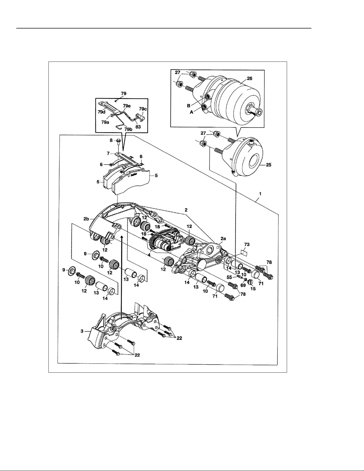
Disc brake DB19/DB22 Generation 1 - Exploded view....................................................................3
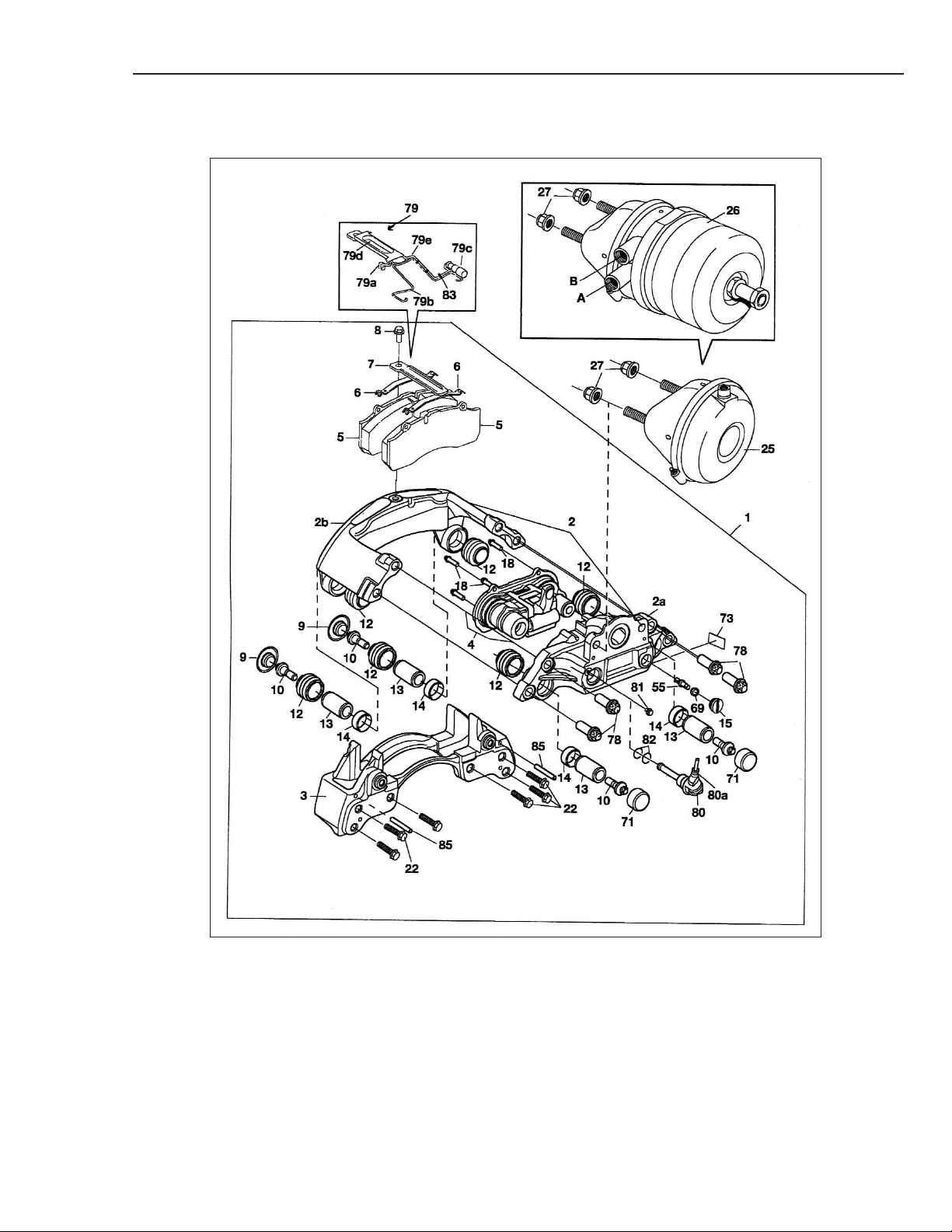
Disc brake DB19/DB22/DB22LT Generation 2 - Exploded view......................................................4
Disc brake component list ................................................................................................................5
Disc brake specifications..................................................................................................................6
Tightening torques............................................................................................................................7
Wear limits........................................................................................................................................7
Operation of Product...................................................................................................................................8
General instructions
Instructions .....................................................................................................................................11
Recycling ........................................................................................................................................11
Cleaning..........................................................................................................................................11
Surface finishing ............................................................................................................................11
Brake force distribution...................................................................................................................12
Inspection/checks/adjustment
Inspection intervals ........................................................................................................................13
Inspection and checks....................................................................................................................14
Function test...................................................................................................................................18
Initial setting. ..................................................................................................................................19
Lubrication. .....................................................................................................................................20
Service
Replacing brake pads ....................................................................................................................21
Removing disc brake unit ..............................................................................................................23
Installing disc brake unit.................................................................................................................23
Replacing protection boots (common thrust plate) .......................................................................24
Replacing protection boots (two separate thrust plates)................................................................27
Replacing slide pins, slide bushings and protection boots ...........................................................30
Replacing caliper housing (mechanism) ........................................................................................35
Replacing brake chamber .............................................................................................................38
Replacing spring brake chamber ..................................................................................................41
Replacing radial seal and adjustment shaft ..................................................................................44
Troubleshooting..........................................................................................................................................45
Tools ........................................................................................................................................................47
1
2
Introduction
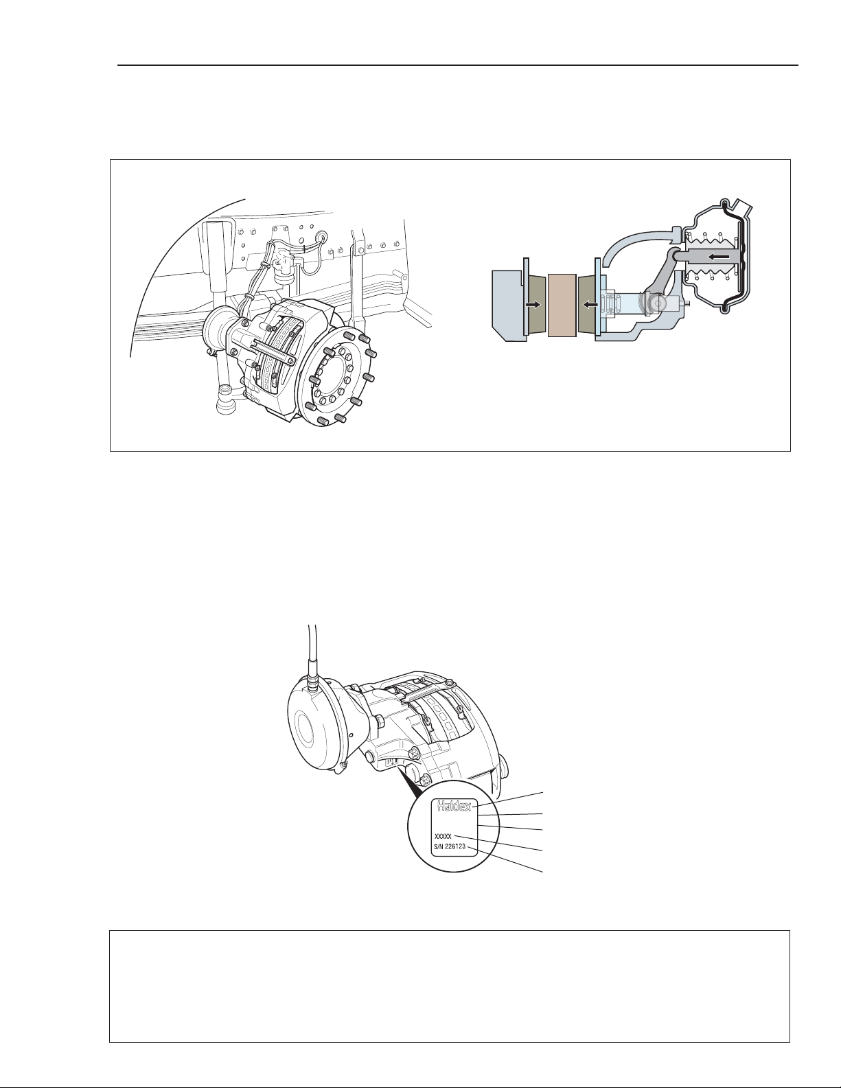
The Haldex disc brake is designed to provide high performance coupled with low weight, durability and a
minimum number of wearing parts. Floating, twopiece calipers are used. Brake pad wear is compensated for by an automatic clearance adjustment mechanism. The mechanism, which is activated by the brake
chamber, acts on a thrust plate which presses the inner
brake pad against the rotor, which then causes the
caliper to move (float) laterally, so that the outer
brake pad also comes in contact with the rotor. The
caliper moves on slide pins. Where the rotor also
serves as a parking brake, the mechanism is activated
by a spring brake chamber.
Introduction
Product identification
Type and serial numbers are stamped on an identification plate fixed to the caliper.
1. OEM/Haldex logo 5. Haldex S/N 226123 (example)
2. OEM P/N (if required) 2 = year, 2002
3. Haldex (origin) assembled in the U.S.A. 26 = week number.
4. Haldex P/N xxxxx 123 = sequential number
1
4
5
3
(2)
Assembled in USA
Haldex Disc Brakes
DB19/DB22 Generation 1
3
See Component List on Page 5.
4
Haldex Disc Brakes
DB19/DB22/DB22LT Generation 2
See Component List on Page 5.

Component list
Haldex Disc Brakes
Component list
DB19/DB22/DB22LT
1 Disc brake assembly
2
Caliper assembly
2a Caliper housing
2b Caliper bridge
3 Carrier
4 Adjuster Mechanism
5Pad
6 Pad spring
7 Pad retainer
8 Bolt
9 Protection cap
10 Slide pin attaching bolt
12 Protection boots
13 Slide pin
14 Slide bushing
15 Plug
18 Torx bolt
22 Bolt
25 Brake chamber
26 Spring brake chamber
27 Fixing bolt
28 Thrust plate
29 Thrust plate clip
30 Protection spring
32 Protection boots
33 Adjuster Mechanism Cover
34 Circlip
35 Adjustment screw
37 Bushing
38 Return spring
41 Cross bar
43 Needle bearing (outer)
44 Lever
45 Retainer
46 Rivet
47 Guide pin
48 Needle bearing (inner)
48a Slide bearing (inner)
50 Washer
53 Bearing sleeve
54 Adjuster
55 Adjustment shaft
59 Washer
60 Circlip
61 Clamp
62 Housing (adjuster)
63 Adjustment spring
64 Circlip (small)
64a Circlip (large)
66 Friction spring (one-way)
67 Hub
68 Companion sleeve
69 Radial Seal
71 Protection cup
73 Data plate
74 Adjustment sleeve (driving)
75 Adjustment sleeve (driven)
76 Pin
77 Gear wheel
78 Torx bolt
79 PWI
79a PWI connectors
79b PWI clamp for cable
79c PWI wire connector
79d PWI plate
79e PWI cable
80 PWS
80a PWS connector
81 Bolt
82 O-ring
83 Cable ties/straps
84 Synchronization plate
85 Indicator pin
86 Pin
5
6
Specifications
DB22
DB19
English
Metric
English
Metric
English
Metric
Specifications
DB19 DB22 DB22LT
Wheel size 19.5-22.5 in. 22.5-24.5 in. 22.5-24.5 in.
Max. brake torque with 0.34 COF 159,313 in-lbs. 18 kNm 194,716 in-lbs. 22 kNm 159,313 in-lbs. 18 kNm
Max. brake chamber force 2,698 ft. lbs. 12 kN 3125 ft. lbs. 12.5 kN 2,698 ft. lbs. 12 kN
Number of actuating tappets 2 2 2 2 2 2
Number of slide pins 4 4 4 4 4 4
Threshold Force 11 lbs. 50N 11 lbs. 50N 11 lbs. 50N
Max. brake chamber stroke 2.5 in. 65 mm 2.5 in. 65 mm 2.5 in. 65 mm
Adjustment for excess clearance (see p. 8). 9.8% 9.8% 9.8% 9.8% 9.8% 9.8%
Max. adjustment distance brake lining 1.9 in. 48 mm 2.0 in. 52 mm 2.0 in. 52 mm
Running clearance, brake lining to rotor 0.02-0.04 in. 0.6-1.0 mm 0.02-0.04 in. 0.6-1.0 mm 0.02-0.04 in. 0.6-1.0 mm
Pad lining thickness 0.82 in. 21 mm 0.86 in. 22 mm 0.86 in. 22 mm
Pad backplate thickness 0.35 in. 9 mm 0.31 in. 8 mm 0.31 in. 8 mm
Pad lining area (per pad) 23 in
2
150 cm
2
30.0 in
2
193 cm
2
24.8 in
2
160 cm
2
External diameter of brake rotor 14.8 in. 375 mm 16.9 in 430 mm 16.9 in 430 mm
Brake rotor thickness 1.8 in. 45 mm 1.8 in. 45 mm 1.8 in. 45 mm
Pad weight each 4.2 lbs. 1.9 kg 5.9 lbs. 2.7 kg 4.9 lbs. 2.2 kg
Weight approx. (excl. pads/brake chamber) 73.9 lbs. 33.5 kg 88 lbs. 39.9 kg 73.9 lbs. 33.5 kg
DB22LT

Tightening torques
For number references in parenthesis in the text which do not appear in this section, refer to the
exploded view (p. 3-4)
Follow the vehicle/axle manufacturers recommendations or follow the method described below:
Bolts for carrier mounting (M20, 2.5 pitch) 350+/-25 475+/-34 350+/-25 475+/-34 350+/-25 475+/-34
Torx Bolts (78) for caliper housing/bridge 273-302 390+/-20 391-435 560+/-30 273-302 390+/-20
Torx Bolts for slide pins 148-177 220+/-20 148-177 220+/-20 148-177 220+/-20
attaching bolts (10) Gen 1
Torx Bolts for slide pins 192-221 280+/-20 192-221 280+/-20 192-221 280+/-20
attaching bolts (10) Gen 2
Pad retainer bolt (8) 33-39 45+8/-0 33-39 45+8/-0 33-39 45+8/-0
Fixing bolts (27), brake chamber 133+22/-0 180+30/-0 133+22/-0 180+30/-0 133+22/-0 180+30/-0
* = The bolt must not be re-used
Specifications
DB19 DB22 DB22LT
Wear limits
Pads (5), min. lining thickness 2mm (0.08 in) 2mm (0.08 in) 2mm (0.08 in)
Pads (5), max. uneven wear 1mm (0.04 in) 1mm (0.04 in) 1mm (0.04 in)
Slide pins (13), max. movement 1mm (0.04 in) 1mm (0.04 in) 1mm (0.04 in)
Slide function, max slide resistance 100N (22.5 lbs.) 100N (22.5 lbs.) 100N (22.5 lbs.)
Brake Rotor, min. thickness 37mm (1.45 in ) 37mm (1.45 in) 37mm (1.45 in)
Brake Rotor, max. wear per side 4mm (0.15 in) 4mm (0.15 in) 4mm (0.15 in)
Brake Rotor, max. lateral runout 0.5mm (0.02 in) 0.5mm (0.02 in) 0.5mm (0.02 in)
Brake Rotor, max. thickness variation 0.1mm (0.004 in) 0.1mm (0.004 in) 0.1mm (0.004 in)
DB19 DB22 DB22LT
ft. lbs. ft. lbs. ft. lbs.
Nm
Nm Nm
7
8
Operation of product
For number references in parenthesis in the text which do not appear in this section, refer to the
exploded view (p. 3-4)
Operation of product
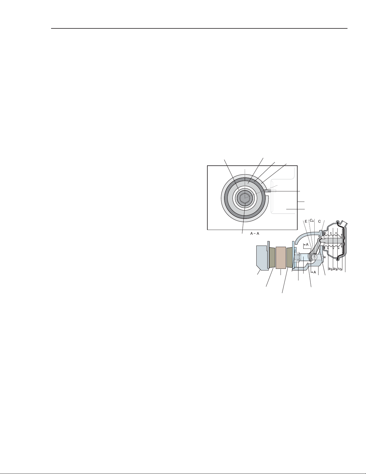
Rest position
66
68
63
62
47
54
44
74
2
A
28
35
41
74/75
2
44
25/26
5 (inner)
5 (outer)
Actuation/release of brake
During braking, lever (44) is actuated by brake
chamber (25/26). The inner section of lever (44)
presses the cross bar (41) axially towards the
brake disc (A). The force is transferred from the
cross bar (41) via adjustment sleeves (74/75),
adjustment screws (35) and the thrust plate (28)
to the inner brake pad (5). As the brake pad (5)
comes into contact with the rotor (A), the caliper
(2) moves laterally on the slide pins (13) to allow
the outer pad (5) to contact the rotor (A). When
the brake is released, return spring (38) forces
cross bar (41) back to its rest position, allowing
the design clearance between pad (5)
and rotor (A) to be achieved.
Automatic adjustment
Adjustment is based on the clearance principle.
The braking sequence is split into three phases:
design clearance C, excess clearance Ce (which
must be adjusted out), and the elasticity phase E.
These phases take place when the brakes are
activated and released. The lever (44) activates
the adjuster unit (54) by means of a guide pin
(47). The clearance between the guide pin (47)
and the slot in the adjuster unit housing (62)
determines the clearance between the brake pads
(5) and the rotor (A).The adjuster unit (54) in turn
rotates the adjustement sleeve (74), which is
threaded around the adjustment screw (35). The
thrust plate (28) is held in position on the end
pins of the adjuster screws (35) by clips (29).The
adjustment screws (35) are prevented from
rotating/following the adjuster sleeves (74/75)
by guides on the thrust plate (28). The second
adjustment sleeve (75) is synchronized and
driven by a gear mechanism which consists of
gear wheels (77) attached to each of the two
adjustment sleeves (74/75) plus an intermediate
gear wheel. (Three gear wheels (77) in total).
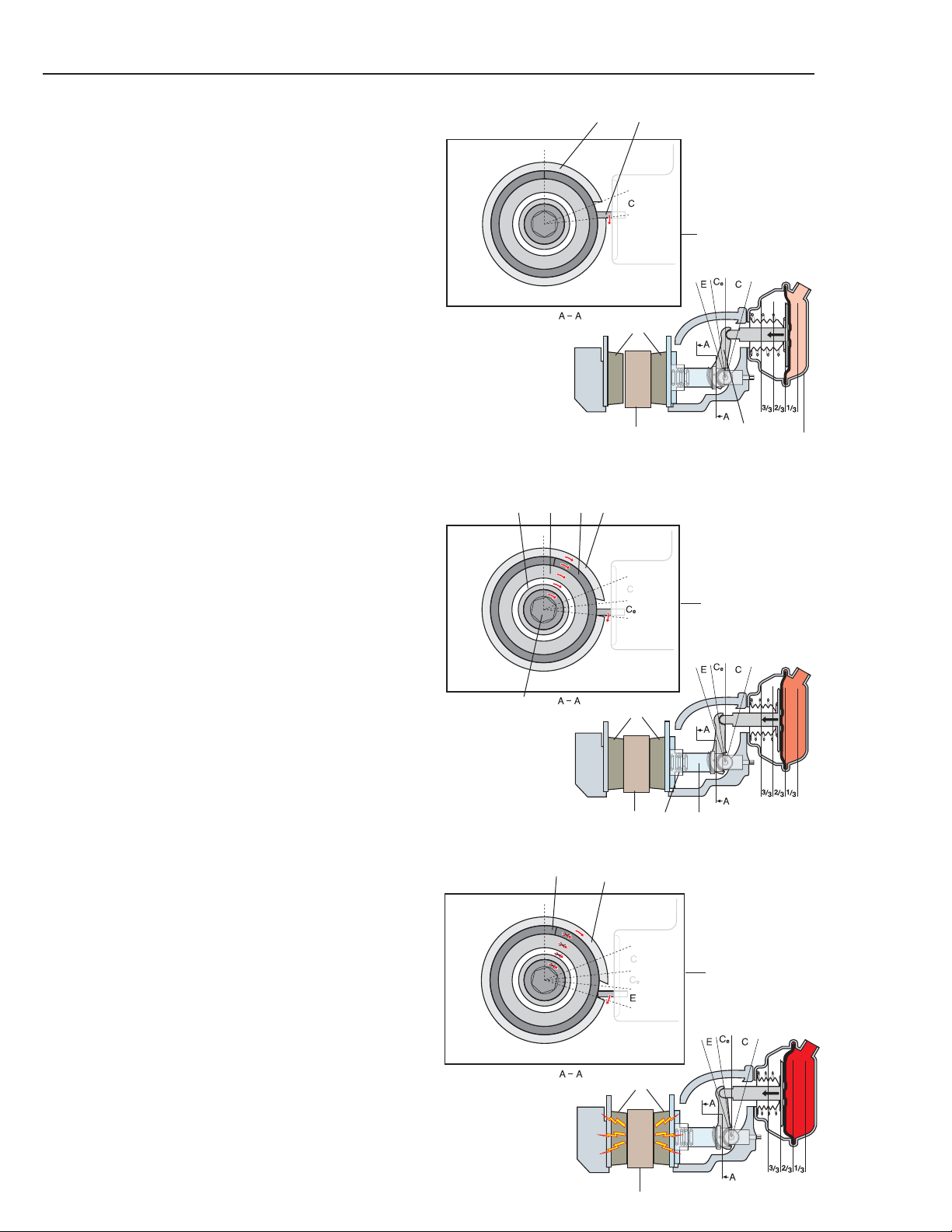
Application
C - During the forward stroke through C, the design
clearance between pads (5) and rotor (A) is measured.
The clearance between the guide pin (47), which is
attached to the lever (44) and the slot in the adjuster
unit housing (62) determines the magnitude of the
forward stroke before the adjustment process begins.
Ce - If there is any clearance between the rotor (A)
and the brake pad (5) when the thrust plate (29) has
moved axially through the design clearance C, the
adjuster unit (54) rotates the adjuster sleeves (75/75).
The adjustment screws (35) are held in position by the
thrust plate (28) and are therefore prevented from
turning. Rotation of the adjuster sleeves (74/75) in
relation to the adjustment screws (35) removes a percentage of the measured excess clearance Ce.
In adjuster unit (54), turning movement is transferred
from the housing (62) via adjustment spring (63),
companion sleeve (68), one-way spring (66) to the
adjustment sleeves (74/75), which are threaded
around the adjustment screws (35).
E – When pads (5) come into contact with rotor (A),
the braking enters elasticity phase E, the torque rises
and adjuster unit (54) stops adjusting. The continued
rotational movement which now occurs in adjuster
unit (54) is allowed by rotating housing (62) in relation to adjustment spring (63).
Operation of product
54
25/26
44
Clearance phase
62
47
5
A
Adjustment phase
66
68 63 62
74
54
35
74/75
5
A
A
Elasticity phase
62
63
5
9
10
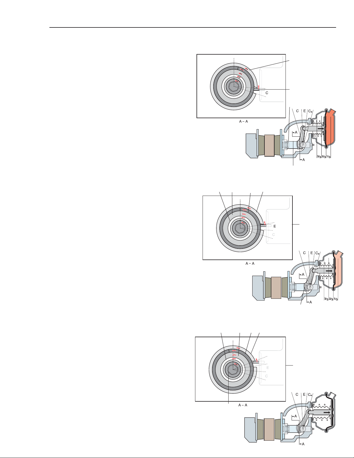
Release
The first part of the return stroke is a combination of
elasticity phase E and design clearance C. Any residual part of the return stroke is excess clearance Ce
which is adjusted out during subsequent braking.
During the return stroke, return spring (38) ensures
that cross bar (41) travels back.
C – During the first part of the return stroke, the force
on the brakes decreases. The guide pin (47) moves to
the opposite side of the slot in the adjuster unit housing (62) = transition of design clearance.
Operation of product
Clearance phase
62
47
41
38
E – Corresponds to forward stroke movement through
E. Adjuster unit housing (62), adjustment spring (63)
and companion flange (68) are rotated in relation to
the adjustment sleeve (74/75), which remains stationary. Movement between the companion flange (68)
and the adjustment sleeve (74) is taken up by the oneway spring (66).
Ce – During the last part of the return stroke (corresponding to the movement of the forward stroke
through Ce), rotational movement in adjuster unit
(54) continues as described under E until adjuster
mechanism (4) reaches its rest position.
The brake is now back in its rest position.
Adjustment phase
66
68 63 62
74
54
Elasticity phase
62
54
74
63
68
66
General Instructions
• Always follow the vehicle manufacturer’s safety instructions when working on the vehicle.
• Follow the vehicle manufacturer’s instructions for recommended practices not described in this manual.
• Comply with local safety regulations.
• Work must be carried out by trained personnel.
• Sudden release of tensioned springs (e.g. the spring brake part of the brake chamber or the disc brake
return spring) may cause injury.
• Use recommended tools only.
• Release pressure from lines and components before disassembly.
• Chock at least one of the vehicle’s axles to prevent involuntary movement of the vehicle.
• Before releasing the vehicle back into service, perform a brake operational check and test the vehicle
to make sure that the brakes are working correctly.
means that special attention is required!
Instructions
Recycling
When replacing the disc brake or parts thereof, the components removed must be recycled/destroyed in
compliance with applicable environmental legislation, regulations and provisions.
To avoid causing damage or displacing hoses, seals and other components
when cleaning/washing/removing snow/ice it is important to take care
when using chemicals, high pressure cleaner or cleaning tools.
Cleaning
For the disc brake’s function it is important to keep it clean so its normal movements are not limited by mud,
ice, snow, objects etc.
!
!
The result of damage may be immediate loss of the brake function or ingress of moisture/dirt and in turn
function irregularities.
This symbol
Surface finishing for disc brake
Surface Coating
Care must be taken to ensure that painting and/or undercoating does not cause damage and/or restrict the natural
movement or operation of the disc brake.
All contact surfaces, brake pads, rubber parts and rotor friction surfaces must therefore be protected or masked.
The mechanism (4) must be protected from the ingress of paint (e.g. if brake chamber (25/26) is not installed).
The following areas must not be painted:
Protection boots (12/32), radial seals (69), brake pads (5) (complete assembly), the swept area of the disc,
mounting surfaces of the assembly and all bolted connections.
11

12
Brake force distribution
It is important that the distribution of brake force (between axles/vehicles) in a vehicle combination is adapted
so that the brake force for each axle/vehicle is proportioned in accordance with the legally applied braking calculations.
If brake force is not correctly distributed it can lead to excessive braking of a vehicle and/or one or more axles
in the combination. This can result in overheating, accelerated wear and damage to the disc brake, pads, brake
discs, tires and wheel components.
Instructions
!
WARNING: Avoid creating dust. Possible cancer and lung disease hazard.
While Haldex does not offer asbestos brake linings, the long term affects of some non-asbestos
fibers have not been determined. Current OSHA Regulations cover exposure levels to some
components of non-asbestos linings but not all. The following precautions must be used when
handling these materials.
ⓦ Avoid creating dust. Compressed air or dry brushing must never be used for cleaning
brake assemblies or work area.
ⓦ Haldex recommends that workers doing brake work must take steps to minimize
exposure to airborne brake lining particles. Proper procedures to reduce exposure
include working in well ventilated area, segregation of areas where brake work is
done, use of local filtered ventilation systems or use of enclosed cells with filtered
vacuums. Respirators approved by the Mine Safety and Health Administration (MSHA)
or National Institute for Occupational Safety and Health (NIOSH) should be worn at all
times during brake servicing.
ⓦ Workers must wash before eating, drinking or smoking; shower after working and
should not wear work clothes home. Work clothes should be vacuumed and laundered
separately with out shaking.
ⓦ OSHA Regulations regarding testing, disposal of waste and methods of reducing
exposure for asbestos are set forth in 29 Code of Federal Regulations §1910.001.
These Regulations provide valuable information which can be utilized to reduce
exposure to airborne particles.
ⓦ Material Safety Data Sheets (MSDS) on this product, as required by OSHA, are
available from Haldex.
13
Inspection/checks/adjustment
Inspection/checks/adjustment
For number references in parenthesis in the text which do not appear in this section, refer to the exploded
view (p. 3-4).
Clean the disc brakes, removing any dirt and dust. Use dust removal equipment
or a vacuum cleaner but do not use compressed air - inhaling dust particles may
be harmful to your health! See Cleaning for instructions.
Do not disassemble the Torx bolts (78) that hold the caliper housing (2a) and
caliper bridge (2b) together!
IMPORTANT!
Read the safety instructions carefully. See the section entitled Safety.
The vehicle manufacturer’s instructions should also be followed.
If the disc brake is equipped with a parking
brake function, ensure that the spring brake
chamber is fully retracted and mechanically
secured in the released position.
See the vehicle manufacturer’s instructions
Visually Inspect the following items every 3 months.
·
Brake Pads 3 month intervals
· Brake Disc 3 month intervals
Check the following items regularly as indicated. Refer to the instructions
provided in the “Inspection” section.
·
Check brake pads 6 month intervals
· Check brake disc 6 month intervals
· Check slide function 6 month intervals
· Check play inside pins 12 month intervals
· Check protection boots 12 month intervals
!
!
!
!
Inspection and checks
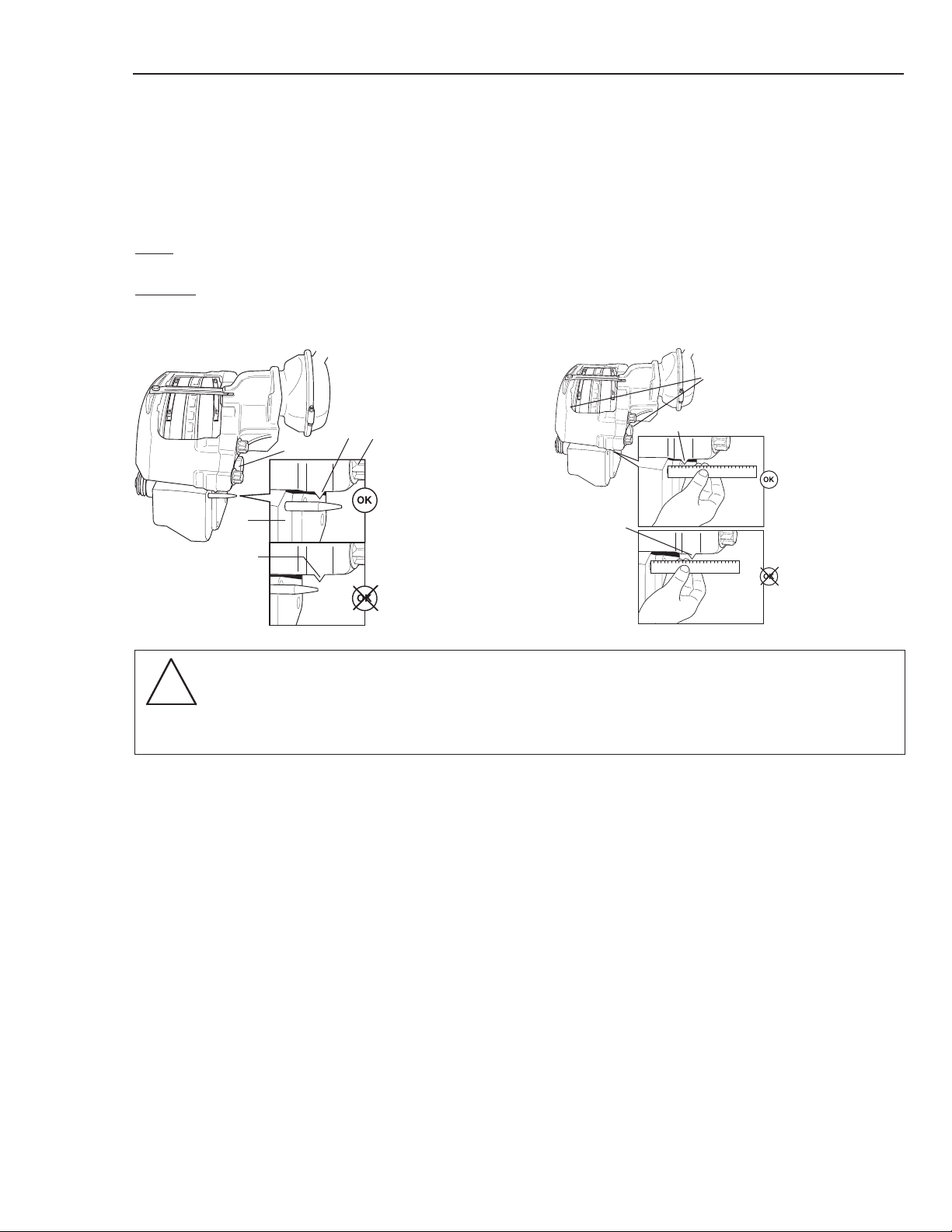
Inspection of pad wear, visual
An indication on the degree of pad wear can be obtained (without removing the wheels) by examining the position of pointer A on the brake caliper assembly (2) in relation to carrier (3). Methods/specifications are the same
for DB19, DB22 and DB22LT. See method descriptions with and without indicator pin below.
W
ith
indicator pin: Examine the position of pointer A in relation to the tip of the indicator pin. See Fig.1.
W
ithout
indicator pin: Use a rigid ruler to measure the distance between carrier assembly (3) and indicator A.
New pads (5) 27 mm (1 1/16 in.) Worn out pads (5) 47 mm (1 7/8 in.) See Fig.2.
NOTE
Inspection procedure only indicates the degree of wear of the outer pad (5)!
To accurately determine the degree of pad wear see Inspection/checks/adjustment,
’Checking pad wear’ [with pads (5) removed] on page 15.
New pads
(5)
27 mm
(1 1/16 in.)
Worn out
pads (5)
47 mm
(1 7/8 in.)
A
A
2
Fig 1
3
A
New Pads
Worn out pads
71
2
A
The checks outlined in subsequent sections should be conducted with brake pads (5) removed. See section entitled ’Replacing brake pads’ for instructions regarding the removal of brake pads.
Inspection of rotors, visual.
Visually inspect the inside and outside faces of the rotors for damage, wear and cracks. (The outside face of the
rotors can be inspected through the holes in the wheel or by using a mirror and looking from the inside of the
wheel outwards). To assess any damage see ’Condition of the brake rotor’ later in this section.
In case of doubt concerning the extent of the damage, remove the wheel to allow closer inspection. Refer also to
the axle/vehicle manufacturer’s instructions.
If there are signs of overheating on the rotor, inspect the protection boots, brake pads and springs for damage (12
and 32). Grease escaping from the wheel hub can also be a sign of overheating. See ’Function test’ and ’Brake
force distribution’ for more information on checking the operation of the disc brake and adjusting the operating
system and brake force if overheating has occurred.
14
Inspection/checks/adjustment
Fig 2
!

Inspection/checks/adjustment
15
Checking pad wear
Measure the distance from backplate (A) to wear surface (B) of
pad (5) in four places, as shown.
Minimum permitted lining thickness (friction material) = 2 mm
(approximately 1/8 in.) New pads, lining thickness = 22 mm
(approximately 7/8 in.) Replace pads if they are worn out or if
they are expected to be before the next service.
Also check that pads (5) are evenly worn, max. 1mm (0.04 in.) uneven wear (measured at four points). In
the event of uneven wear, check the sliding function of caliper (2) on slide pins (13). See ’Checking slide
function’ later in this section.
Also check that there is no dirt between the thrust plate (28) and pads (5) and that the thrust plate (28) is
adjusted flush during function testing. [Both adjustment screws (35) must be adjusted by the same amount].
See ’Function test’ later in this section for procedure.
NOTE: Driving with light
brake applications may result in increased wear on the inner brake pad.
A
B
Checking brake rotor
Measure the thickness of the rotor (A) using a slide caliper. If the
rotor (A) has a wear ridge, the measurement can be performed
using two spacers (B) (e.g. 5 mm (0.20 in) thick flat washers).
Reduce the measured dimension by the total thickness of the two
spacers (B). Min. thickness of brake disc 41 mm (1.6 in.). In a
ventilated rotor, max. wear is 2 mm (0.08 in.) per side. Rotor (A)
must be replaced if the wear limits have been exceeded.
Lateral runout
Check/adjust wheel bearing end play in accordance with the vehicle
manufacturer’s instructions.
Measure the lateral runout of the rotor (A) by attaching a magnetic stand
complete with a dial gauge on carrier (3). Point the tip of the dial gauge
towards the side of brake disc and rotate the rotor (A) > one turn. Max
lateral runout 0.5 mm (0.02 in.).
NOTE: Do not include wheel bearing end play in the measurement!
A
3
B
B
A
B
A

Condition of the brake rotor
Check the rotor (A) for cracks and wear tracks. Also refer
to the vehicle/axle manufacturer’s instructions.
If action is required, see the vehicle/axle manufacturer’s
instructions for replacing the brake rotor.
Crack length
< Less than 75% of brake
rotor width
Permitted cracking
Crack length
< More than 75% of brake
rotor width
Non-permitted cracking,
replace rotor
Checking slide function
This check is done after the pads have been removed.
Check the sliding motion of the caliper assembly (2)
on slide pins (13). The caliper assembly (2) must be
free to slide on the slide pins (13), max. slide resistance 22.5 lbs. If slide resistance is higher, check that
the movement is not hindered by external dirt, foreign
objects, etc. If caliper is not sliding freely, see section
entitled ‘Replacing slide pins, slide bushings and protection boots’.
Checking play in slide function
Measure the play in the outer slide pins (13) by
attaching a magnetic stand complete with a dial gauge
on carrier (3), with the tip of the dial gauge on point
(A) as illustrated. Lift and lower the caliper assembly
(2) outside the brak
e rotor and read off the dial gauge.
Repeat the procedure inside the brake rotor for the
inner slide pins (13) and measure at point (B). The
method for obtaining a play measurement must be
adapted to the ’clock position’ of the disc brake. The
example here shows the disc brake in the 12 o’clock
position. Max. play 1 mm (0.04 in.). If corrective
measures are required, see the section entitled
’Replacing slide pins. slide bushings and seals’.
A
3
13
13
B
2
13
Max 22.5 lbs.
(100 N)
IMPORTANT! The disc brake
caliper must be mounted on the
axle and the bolts (22) fully
tightened for this check.
16
Inspection/checks/adjustment
!

Inspection/checks/adjustment
17
Checking slide pin protection boots
Check each of the two protection caps (9) and six protection boots (12). Also check the two protection cups
(71).
If there are signs of cracks or other damage, the
protection cups (71), protection boots (12) and protection caps (9) must be replaced!
If action is required, see the section entitled ’Replacing
slide pins, slide bushings and boots
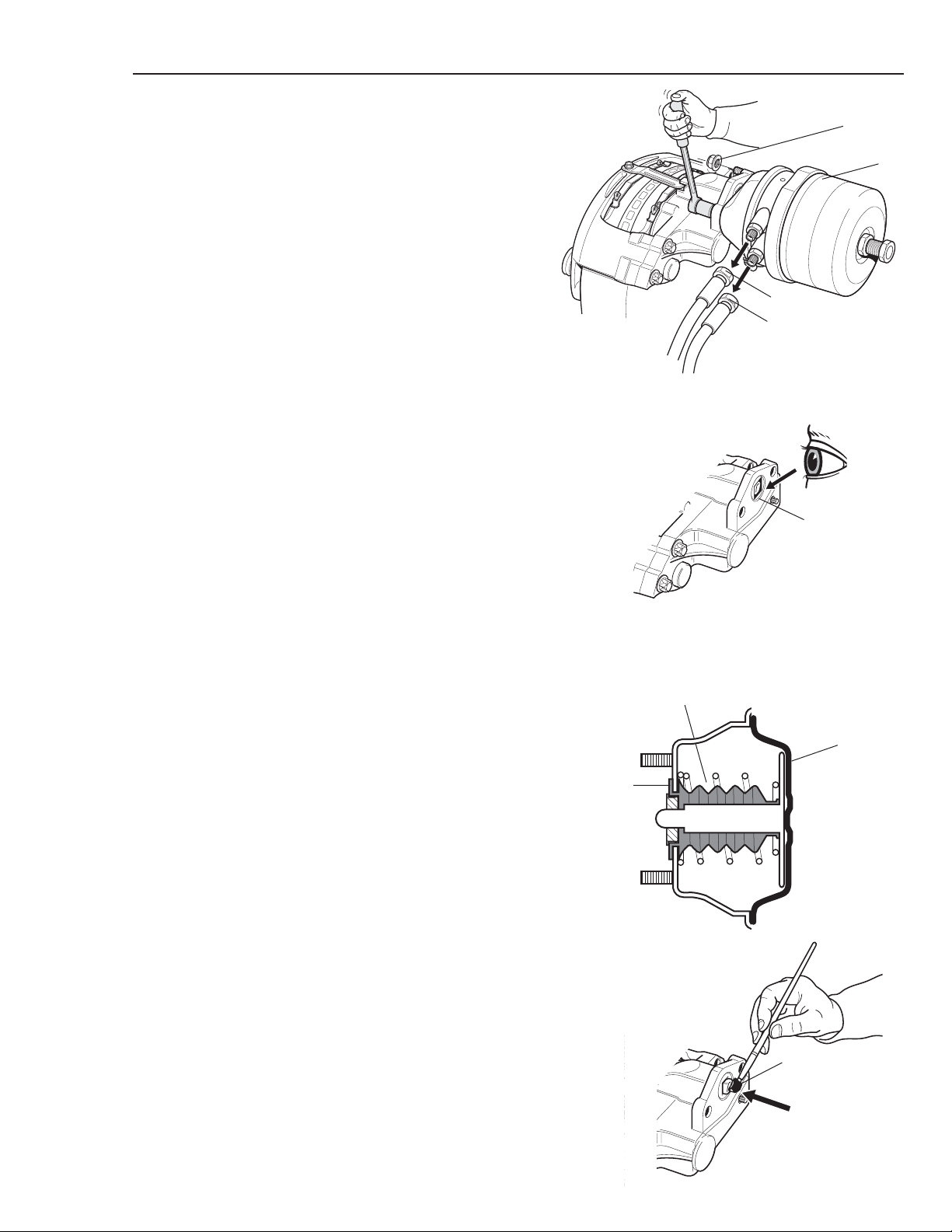
Checking adjustment screw
protection boots
Using an 8 mm wrench, rotate adjustment shaft (55)
clockwise until protection springs (30) become fully
visible. NOTE! the thrust plate (28) must be no
more than 50 mm (approximately 2 in.) from
adjuster mechanism cover (33)!
Inspect protection springs (30). Pull protection
springs (30) back and inspect protection boots (32).
If there are signs of cracking or other damage,
the protection springs/boots must be replaced!
Turn adjustment shaft (55) counter-clockwise until
thrust plate is fully retracted and resistence is felt.
Check that the protection springs (30) are
correctly seated so that they are not crushed or
damaged!
CAUTION: Continuing to rotate the adjustment
shaft when the thrust plate is fully retracted can
result in internal damage to the disc brake
mechanism.
If action is required, see the section entitled
’Replacing adjustment screw protection boots.’
The checks outlined in this section should be conducted with brake pads (5) removed. See section entitled ’Replacing brake pads’ for brake pad installation
instructions and the section entitled ’Initial setting’.
max
50 mm
(approximatly
2 in.)
33
30
28
32
71
12
9
12
12

Function test
For number references in parenthesis in the text which do not appear in this section, refer to the
exploded view (p. 3-4)
• Lift up and support the axle in accordance with the vehicle manufacturer’s instructions.
IMPORTANT!
Read the safety instructions carefully. See the section entitled ’General Instructions’.
The vehicle manufacturer’s instructions should also be followed.
• Check that the wheel can be turned freely.
• Remove the plug (15)
• Release the brake adjustment by using an 8mm wrench to turn the adjustment shaft (55)
3/4 of a turn counter-clockwise.
Leave the wrench in position on the adjustment shaft
(55). Apply the brakes five times. The wrench must
move on each application, showing that the automatic adjustment is working.
NOTE! The wrench must be allowed to move
freely!
If the wrench moves back and forth or does not move
at all, the mechanism is faulty and must be replaced.
See section entitled ‘Replacing the caliper housing
(2a) [including adjuster mechanism (4)]’.
Carry out initial setting as described on the next page.
Optional clearance checking procedure: only
required for an approximation of the clearance
between the rotor (A) and the brake pads (5).
General clearance check.
x5
A
55
A
After the function test has been completed, activate the brakes until the wrench no longer moves.
Then turn the wrench clockwise by hand until the
brake pads (5) touch the rotor (A). If the wrench
can be turned between 1/8 and 1/4 of a turn then
the clearance is within the specified value. (See
’Specifications’ for data). Then rotate the adjustment shaft (55) 1/4 turn counter-clockwise.
18
Inspection/checks/adjustment
!

Initial Setting
19
Initial setting
Check that brake rotor (A) can be turned freely.
Using an 8 mm wrench, turn the adjustment shaft
(55) clockwise (Do not force) until both pads (5)
touch rotor (A). Then turn it 1/4 turn counter-clockwise to obtain a basic clearance between pads (5) and
rotor (A). Check that brake rotor can be turned freely.
Remove the wrench.
Check the radial seal (69) for wear and damage.
Clean/replace if required. See replacement instructions
in the section on ‘Replacing radial seal and adjustment
shaft’ (page 44).
Fitting the plug (15) (where applicable): Lubricate the
inside and outside of the plug (15) and the recess for
the adjustment shaft, using grease P/N 89652 or
equivalent EP chassis grease.
Then install the plug (15) for the adjustment shaft (55).
Check that the plug (15) for the adjustment shaft (55)
is pushed fully into place (See diagram).
IMPORTANT!
Never use an impact wrench
or other similar device as they
will damage the adjustment
mechanism!!
A
A
To provide the correct clearance between the brake
rotor (A) and brake pads (5) the mechanism will make
the final adjustment itself when the brakes are applied
the next few times.
55
15
EP Chassis Grease
15
EP chassis
Grease
55

Lubrication
IMPORTANT!
Read the safety instructions carefully. See the section entitled ’General Instructions’.
The vehicle manufacturer’s instructions should also be followed.
General
Use specified lubricant only!
To safeguard operation of the disc brake it is important only to use specified lubricants for the lubrication
point concerned. Apply the correct amount of lubricant - do not apply excessive quantities to avoid lubricant being dispersed or causing damage during the
natural movements of the brake (on pad friction surfaces, on the brake rotor, in protection boots etc.).
Mechanism
Before installing the brake chamber (25/26), lubricate
the recess in the lever (44) where the brake chamber
(25/26) pushrod fits. Adjuster mechanism (4) is lubricated in the factory and, as such, does not normally
require further lubrication. If additional lubrication is
required (e.g. when removing/fitting the mechanism)
see the section entitled ’Specifications’ for more
information about the type of lubricant that should be
used.
20
Inspection/checks/adjustment
!

Replacing brake pads
21
Service
Replacing brake pads
For number references shown within parenthesis that do not appear in this section, see the exploded
view (p. 3-4)
• Always replace pads on both sides of the axle
at the same time.
• Replace pads with original equipment material or equivalent orginal equipment material.
Do not remove or loosen the Torx bolts (78) that hold the caliper housing (2a) and
caliper bridge (2b) together!
IMPORTANT!
Follow the safety instructions. See the section entitled ’General Instructions’.
The vehicle manufacturer’s instructions should also be followed.
• Follow the vehicle manufacturer’s instructions to chock the wheels on an axle which is not to be raised.
• Lift the axle, support and remove the wheels in accordance with the vehicle manufacturer’s instructions.
Clean the brakes, removing any dirt and dust. Use dust removal equipment or
a vacuum cleaner but do not use compressed air - inhaling dust particles may
be hazardous to your health! See, Cleaning, for instructions.
If the disc brake is equipped with a parking brake
function, ensure that the spring brake chamber
is fully caged in the released position.
See the vehicle manufacturer’s instructions for more information.
!
!
!
!

Removing pads
Using an 8mm wrench, release the brake
adjustment by turning the adjustment shaft (55)
counter-clockwise until the thrust plate (28) is
fully retracted.
55
Release
8
7
NOTE!
When releasing the brake adjustment it is important
that the protection springs (30) are correctly seated in
the mechanism cover (33) so that the thrust plate (28)
is free to retract without damaging the springs.
The thrust plate (28) should come to a distinct stop.
Important, do not over tighten; or internal damage
will occur.
Remove bolt (8) and pad retainer (7).
Remove pad springs (6). Remove pads (5).
Clean the pad (5) contact surfaces on thrust plates
(28), in caliper assembly (2) and on carrier (3) with a
wire brush. Do not grind!
Perform in service checks in section titled
‘Inspection/checks/adjustment’.
33
30
33
28
IMPORTANT!
Never use a impact wrench or
similar device as this will
damage adjuster mechanism (4)!
28
6
5
30-37 ft. lbs.
(45±5 Nm)
Installing brake pads
Using an 8mm wrench, ensure that the adjustment
shaft (55) is fully retracted. Check that the protection
springs (30) are correctly seated and are not damaged
and that the thrust plate (28) is fully retracted. Check
that the pad (5) contact surfaces in the disc brake are
clean.
7
6
5
Insert the brake pads (5), insuring that friction
material faces the brake rotor.
Install the pad springs (6), pad retainer (7) and secure
with bolt (8). Tighten to a torque of 30-37 ft. lbs.
(45±5 Nm).
Perform ‘Initial Setting’ on page 19.
8
22
Replacing brake pads

Removing and Installing disc brake
23
Removing disc brake
Remove two of the disc brake’s three attaching bolts
(22) on each side.
Insert the pad retainer (7) and secure with bolt (8).
Connect a lifting strap and a suitable lifting device.
Remove the two remaining attaching bolts (22), lift
and remove the disc brake.
22
22
7
8
Installing disc brake
Check that the surfaces for fitting to the axle, brake
chamber (25/26) and pads (5) are clean.
Insert pad retainer (7) and secure with bolt (8).
Connect a lifting strap and a suitable lifting device.
Lift the disc brake into position.
Follow the vehicle/axle manufacturer’s recommendations for fitting/tightening bolts (22) or follow
the method as described below:
Lubricate bolts (22) with anti-seize compound
P/N 81934 or equivalent.
Always use new bolts (22).
Fit one bolt (22) on each side of the caliper assembly (2).
Remove the lifting strap, bolt (8) and pad retainer
(7).
Fit the other bolts (22) and tighten all bolts according to the vehicle OEM specifications or see the
‘Tightening Torques’ table on page 7.
Check caliper sliding function as instructed on page
16.
Install brake chamber as instructed on page 39.
Install brake pads as instructed on page 21.
Perform Initial setting as instructed on page 19.
22
see vehicle OEM
specifications or
see the ‘Tightening
Torques’ table on
page 7 for torque
specification.

Replacing protection boots on
disc brakes with a common thrust
plate (previous design of ModulX)
Removing protection boots
Protection springs (30) are optional and are therefore
not always fitted (customization). Using an 8 mm
socket, turn the adjustment shaft (55) clockwise so
that the thrust plate (28) moves 35-40 mm (1.4 to 1.6
in.) out from its fully retracted position. Pull back the
protection spring (30) and detach the thrust plate (28)
from the adjustment screws (35) by tapping a screwdriver into the gap between the two adjustment screws
(35) and the thrust plate (28).
Do not damage the adjustment screws (35)/thrust
plate (28)!
NOTE! The clips (29) will be forced out of their slots
when the thrust plate (28) comes loose.
Remove protection springs (30).
Clean the adjuster mechanism cover (33) and protection boots (32).
To prevent any change being made to the synchronisation of the thrust plate (28) it is important to hold
the adjustment screws (35) in position so that they
cannot rotate during the following steps!
Remove the protection boots (32) from the adjustment screws (35) and adjuster mechanism cover (33)
by prying them off with a screwdriver. Do not dam-
age the sealing surfaces! Avoid damaging the protection boot (32) mounting surfaces in the adjuster
mechanism cover (33)!
Do not pry out thrust plate (28)
against adjuster mechanism
cover (33) (with a screwdriver or
similar tool) - the needle bearings
(43/48) may be displaced and be
damaged!
29 28
30
35
35
35
32
32
Replacing adjustment screw protection boots
24
33
Common
Thrust Plate
Two Separate
Thrust Plates
!

Replacing adjustment screw protection boots
25
Fit the thrust plate (28) in place and hold it in
position against the adjustment screws (35) [with
the clips (29) removed]. Check the two holes in the
thrust plate (28) to ensure that the adjustment screws
(35) are correctly seated. Turn the adjustment shaft
(55) counter-clockwise until the adjustment screws
(35) are fully retracted and then screw them out one
turn. Remove the thrust plate (28).
NOTE! Do not damage the
adjustment screws and/or boot
mounting surfaces, as this
could cause leakage or water
penetration.
Cleaning
Clean the thrust plate (28), adjustment screws (35)
and sealing surfaces in the adjuster mechanism
cover (33).
Make sure that dirt and other
contaminants do not enter
through the openings for the
adjustment screws!
Inspection
Check that the sealing surfaces for the protection
boots (32) in the adjuster mechanism cover (33)
and on the adjustments screws (35) are free from
damage that could cause leakage or water
penetration.
Check that the thrust plate clips (29) are intact.
Also check the part of the adjuster mechanism (4)
visible beyond the adjustment screws (35), looking
for signs of corrosion, damage and condensation. If
corrosion or damage is visible the complete
adjuster mechanism (4) must be replaced.
See section entitled ’Replacing the adjuster
mechanism’.
55
28
35
28
35
28
28
35
28
3528
35
33
35
!
!

Installing protection boots
Check that the adjustment screws (35) are rotated
into the right position to engage in their guides in
the thrust plate (28). Use a straight edge to check
that the adjustment screws (35) are parallel (i.e. in
their original position). Adjust if necessary. A 1/2
turn = 2 mm (0.08 in.). Lubricate the adjustment
screws (35) threads with grease P/N 89652.
Put the protection boots (32) in place in the adjuster
mechanism cover (33). Press them into their positions using special tool P/N 89778 and a suitable
lever. Insert the lever between the rotor and special
tool P/N 89778. Do not damage the rotor!
Using the thrust plate (28), recheck that the adjustment screws (35) are turned to the correct position.
Then press the protection boots (32) into position
on the adjustment screws (35) using special tool
P/N 89779 and a lever (as described above).
Compress the protection springs (30) if used and
insert them in position in the adjuster mechanism
cover (33) with the smallest end facing the thrust
plate (28). Then press the thrust plate (28) into
place on the adjustment screws (35).
Look through the two holes in the thrust plate (28)
to check that the adjustment screws (35) are correctly seated.
Installing the clips
Place the inner part of special tool P/N 89936 on
a flat surface, such as a work bench, with the large
end downwards and place the thrust plate clip (29)
over the end of the tool. Use the outer part of the
special tool to press the thrust plate clip (29) all the
way down towards the surface. Now center the special tool, with the thrust plate clip (29), over the
adjustment screw (35). Insert a suitable lever
between the rotor (A) and the special tool
P/N 89936 and use it to press the thrust plate clip
(29) into its slot on the adjustment screw (35). Do
not damage the rotor (A)!
Repeat the procedure to install the second thrust
plate clip (29).
Make sure that the protection springs (30) are correctly seated, otherwise they will be damaged!
P/N 89778
P/N 89779
32
32
35
35
P/N 89936
29
P/N 89936
29
P/N 89936
29
35
28
32
32
26
Replacing adjustment screw protection boots

Replacing adjustment screw protection boots
27
Replacing protection boots on disc
brakes with two separate thrust
plates (DB22LT and updated
design DB22 and DB19 calipers)
Removing the protection boots
Protection springs (30) are optional and are therefore
not always fitted (customization).
Turn the adjustment shaft (55) using an 8 mm socket
clockwise until the thrust plates (28) are 35-40 mm.
(1.4-1.6 in.) out from their fully retracted position.
Pull back the protection springs (30) if used and carefully pry off the protection boots (32) from the thrust
plates (28) using a screwdriver. Remove the thrust
plates (28) by tapping in a screwdriver and bending
the joint to the adjustment screw (35). Avoid damaging the adjustment screws (35)/thrust plate (28)!
Do not pry off the thrust plates
(28) using a chisel or similar tool
on the adjuster mechanism cover
(33). This could lead to damage
of the adjuster mechanism (4).
Remove the protection springs (30) if used.
Remove thrust plate clips (29).
Turn the adjustment shaft (55) counter-clockwise
until the adjustment screws (35) are fully retracted
and then screw out one turn.
Remove the protection boots (32) from the adjuster
mechanism cover (33) by prying them out with a
screwdriver. Avoid damaging the sealing surfaces!
IMPORTANT! Avoid damaging the
adjustment screws and/or the
seal mounting surfaces!
35
32
28
33
35
32
28
29
Common
Thrust Plate
Two Separate
Thrust Plates
!
!

Cleaning
Clean the adjuster mechanism cover (33), thrust
plates (28) and adjustment screws (35).
Make sure that dirt and other
contaminants do not enter
through the openings at the
adjustment screws!
Where necessary, lubricate the threads on the
adjustment screws (35) with grease P/N 89652.
Inspection
Check that the protection boot (32) mounting surfaces in the adjuster mechanism cover (33) and on
the thrust plates (28) are free from damage.
Check that the thrust plate contact surfaces (28)
and the adjustment screws (35) are free from damage.
Also check the part of the adjuster mechanism (4)
that is visible past the adjustment screws (35) for
corrosion, damage and condensation. If rust/damage has occurred, replace the full caliper housing
(2a) assembly.
See section on ‘Replacing caliper housing’.
Mounting the protection boots
Lubricate the adjustment screw (35) threads with
grease P/N 89652. Put the protection boots (32) in
place in the adjuster mechanism cover (33). Then
press them into position using a special tool
P/N 89778 and appropriate prying device. Bend
using a prying device between the rotor (A) and
special tool P/N 89778. Avoid damaging the rotor!
Fit new thrust plate clips (29) on the adjustment
screws (35).
Turn the protection springs (30) if used together
and put the adjuster mechanism cover (33) in place
with the small diameter directed to the thrust plate
(28).
32
33
35
A
P/N 89778
29
28
Replacing adjustment screw protection boots
!

Replacing adjustment screw protection boots
29
Press the protection boots (32) in place on the thrust
plate (28) with your fingers and then press the adjustment screw (35) in place using the special tool
P/N 89778 and a suitable prying device.
Repeat for the other protection boots (32), adjustment screws (35) and thrust plates (28).
If protection springs (30)
are used: make sure they
are correctly positioned in
their seats and do not
damage the protection
boots (32)!
Replace brake pads as instructed on page 21.
32
28
35
28
!
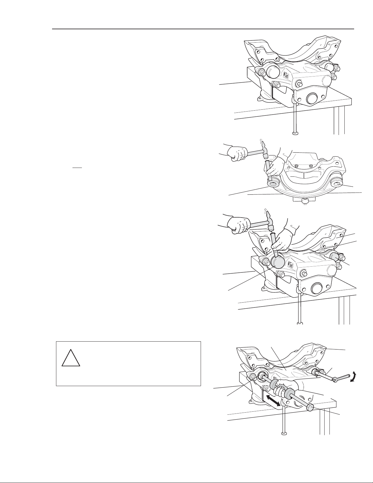
Removing slide pins, slide bushings
and protection boots
Remove brake pads as described on page 21.
Remove brake chamber as described on page 38.
Position the disc brake in a vice. Use protection jaws.
9
9
71
2
3
71
Remove the two protection caps (9) and the two
protection cups (71) using a hammer and chisel.
The protection caps (9) and protection cups (71)
must not
be re-used.
Remove the slide pin attaching bolts (10) using special tool P/N 81933 (Torx E18 socket). Press the slide
pins (13) back [enough to remove carrier (3) from
caliper assembly (2)] by rocking carrier (3) back and
forth.
NOTE!
Do not use gripping tools or
similar - this will damage the
slide pin sealing surfaces!
If slide pins (13) are seized in carrier (3), cut threads
on the inside of slide pins (13) using an M16x2 tap
and special tool P/N 81920 (slide hammer without
yoke) as a puller.
2
13
▼
P/N 81920
Thread tap
M16x2
3
Replacing slide pins, slide bushings and protection boots
30
!

Replacing slide pins, slide bushings and protection boots
31
NOTE! Only grip on external
surfaces!
Clean the components, removing
any dirt and dust. Use dust
removal equipment or a vacuum
cleaner but do not use
compressed air - inhaling dust
particles may be harmful to your
health!
Remove the four slide pins (13) from the caliper
assembly (2).
Remove the six protection boots (12) by carefully
prying them out.
NOTE! Do not damage the contact surfaces!
2
3
2
12
Remove carrier (3) from caliper assembly (2).
Remove the four slide bushings (14) (which are of
split design) using a small screwdriver. Begin at the
split.
NOTE! Do not damage the mounting surfaces!
Cleaning/Inspection
Clean and check to ensure that the fitting surfaces for
the slide bushings (14), protection boots (12) and protection cups (71) are free from dirt and damage.
14
2
2
13
!
!

Press the slide pins (13) into position in the slide
bushings (14).
Slide pins (13) must be able to slide easily in slide
bushings (14) to ensure that that caliper assembly (2)
floats over carrier (3).
2
13
Installing slide bushings, slide
pins and protection boots
Slide bushings (14) are supplied as a band.
Shape (4 pcs.) slide bushings (14) in 2-steps as shown
in the pictures (the ends of the bushing band must
touch each other) and fit them in position in caliper
assembly (2).
Expand the slide bushings (14) by pressing/twisting
through special tool P/N 81921.
14
14
14
P/N 81921
14
P/N 81921
Replacing slide pins, slide bushings and protection boots
32

Replacing slide pins, slide bushings and protection boots
33
Fit the protection boots (12) in caliper assembly (2)
using special tool P/N 81922.
NOTE!
Protection cups (71) should only be installed after
tightening the slide pin fixing bolt (10) to the required
torque. Refer to the section ‘Tightening Torques’ on
page 7.
Press the end of the protection boots (12) into position on the shoulder on the end of slide pin (13).
Clean the contact surfaces in carrier (3), caliper
assembly (2) and on thrust plates (28). Also clean
pads (5) (if these are to be re-used). Use a wire brush.
Do not grind!
Sparingly lubricate slide pin (13) and carrier (3)
mounting surfaces with anti-seize compound.
P/N 81934 or equivalent.
Press out slide pins (13) so that they are free from carrier (3) during installation.
Lower carrier (3) into position in caliper assembly (2)
and press in slide pins (13) so that they fit on carrier
(3). Do not damage protection boots (12)!
NOTE! Only grip on external
surfaces! Do not damage
the protection boots (12)!
12
P/N 81922
(Consists of three parts)
2
13 12
2
3
2
!

Lubricate the threads on the four slide pin attaching
bolts (10) using anti-seize compound P/N 81934 or
equivalent and screw them into position. Tighten
using a torque wrench and special tool P/N 81933
(Torx E18 socket). Refer to the section ‘Tightening
Torques’ on page 7.
Check that carrier (3) slides easily in caliper assembly
(2).
Max. slide resistance with disc brake assembly (1)
installed on the vehicle axle: 100N (22.5 lbs.) (See
maintenance instructions).
10
P/N 81933
(Torx E18 socket)
Tap new protection caps (9) into position in the outer
ends of the slide pins (13) using a 17 mm socket and
an extension or equivalent diameter tool.
NOTE! The protection caps (9) must go all the way
into the slide pins (13).
Carefully tap new protection cups (71) for inner slide
pins (13) in place in the caliper assembly (2).
71
9
Socket
Extension
9
Replacing slide pins, slide bushings and protection boots
34

Replacing caliper housing
35
Replacing caliper housing/mechanism
For number references shown within parenthesis that do not appear in this section, see the exploded
view (p. 3-4)
IMPORTANT!
Follow the general instructions on page 11 and the vehicle manufacturer’s
instructions.
Follow the vehicle manufacturer’s instructions to chock the wheels on an axle
which is not to be raised.
Lift the axle, support, and remove the wheels in accordance with the vehicle
manufacturer’s instructions.
Clean the brakes, removing any dirt and dust. Use dust removal equipment or
a vacuum cleaner but do not use compressed air - inhaling dust particles may
be hazardous to your health! See ‘Cleaning’ for instructions.
If the disc brake is equipped with a parking
brake function, ensure that the spring brake
chamber is fully retracted and mechanically
secured in the released position.
See the vehicle manufacturer’s instructions for
more information.
Remove slide pins, bushings, protection boots and carrier as instructed on pages 30-31.
Removing caliper housing
Remove the four Torx bolts (78) that hold the caliper
housing (2a) to the caliper bridge (2b), using special tool
P/N 90797 (Torx E20 socket) for DB19 and DB22LT or
P/N 90798 (Torx E24 socket) for DB22.
Remove the caliper housing (2a).
P/N 90797 for DB19/DB22LT
P/N 90798 for DB22
2b
2a
!
!
!

Replacing caliper housing
36
Removing slide bushings from
caliper bridge
Remove the four protection boots (12) by carefully
prying them out.
NOTE! Do not damage the mating surfaces!
Then press both slide pins (13) out of the caliper
bridge (2b)
Remove the two slide bushings (14) (which have a
split design) using a small screwdriver. Begin at the
split.
NOTE! Do not damage the mating surfaces!
Cleaning/Inspection
Clean and check the surfaces of the caliper bridge
(2b) that mate with the slide bushings (14) and protection boots (12) to ensure they are free from dirt and
damage.
Also clean and check the threads of the Torx bolts
(78) in the caliper bridge (2b) and their surfaces that
are in contact with the caliper housing (2a), to ensure
they are not damaged. Otherwise the complete disc
brake assembly (1) must be replaced.
Check the four slide pins (13) for wear and damage,
replace if necessary.

Installing caliper housing
Model Torque Bolt Spec. tool
DB19 273-302 ft. lbs. (390±20 Nm) M16 P/N 90797
DB22 391-435 ft. lbs. (560±30 Nm) M18 P/N 90798
DB22LT 273-302 ft. lbs. (390±20 Nm) M16 P/N 90797
Lightly lubricate the threads and the underside of the
heads on the Torx bolts (78) with oil.
NOTE! do not apply any oil to the joint between the
caliper housing (2a) and the caliper bridge (2b)!
Assemble the caliper housing (2a) and the caliper
bridge (2b) using the four Torx bolts (78).
NOTE! It is important that the Torx bolts turn freely
in the threads in the caliper bridge (2b)!
Tighten diagonally opposing Torx bolts (78) to the
correct torque, using special tool P/N 90797 (Torx
E20 socket) for DB19/DB22LT and P/N 90798 (Torx
E24 socket) for DB22, as specified below.
It is important that all the surfaces in the
joint between the caliper housing (2a)
and the caliper bridge (2b) are dry and
free from contaminants (oil, grease, etc.).
DB19/DB22LT 273-302 lbs. (390±20 Nm)
DB22 391-435 ft. lbs. (560±30 Nm)
P/N 90797 for DB19/DB22LT
P/N 90798 for DB22
Refer to the section ‘Tightening Torques’ on page 7.
Replacing caliper housing
37
Fitting slide bushing to caliper
bridge
Slide bushings (14) are supplied as a strip form.
Shape two slide bushings (14) in two stages as shown
in the pictures (the ends of the bushing band must
touch each other) and fit them in position in caliper
bridge (2b).
Expand the slide bushings (14) by pressing/twisting
through special tool P/N 81921.
Press the slide pins (13) into position in the slide
bushings (14). The slide pins (13) must be able to
slide easily in the slide bushings (14) to ensure that
the caliper assembly (2) “floats” over the carrier (3).
14
14
14
P/N 81921
14
P/N 81921
!

Replacing brake chamber
38
Replacing Brake Chamber
For number references shown within parenthesis that do not appear in this section, see the exploded
view (p. 3-4)
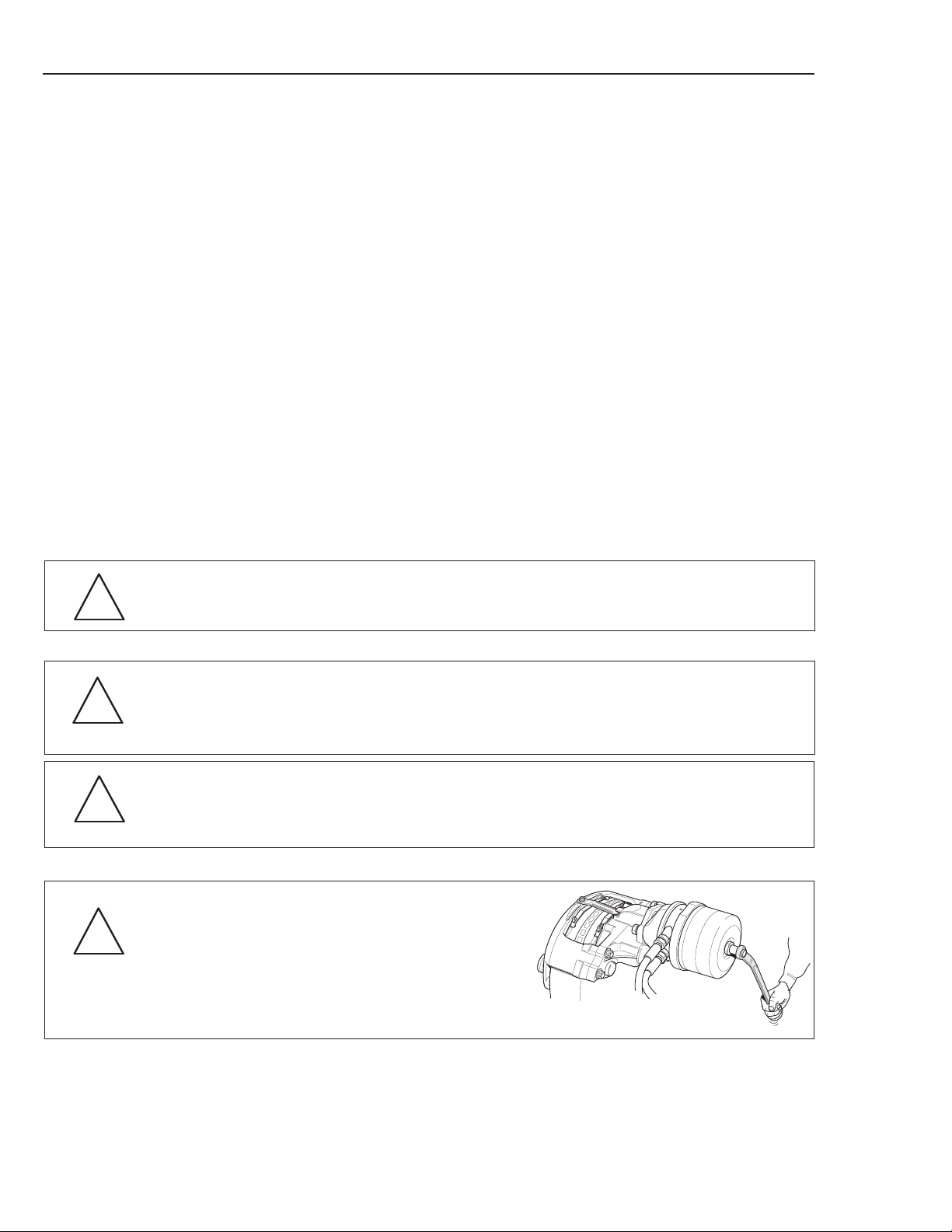
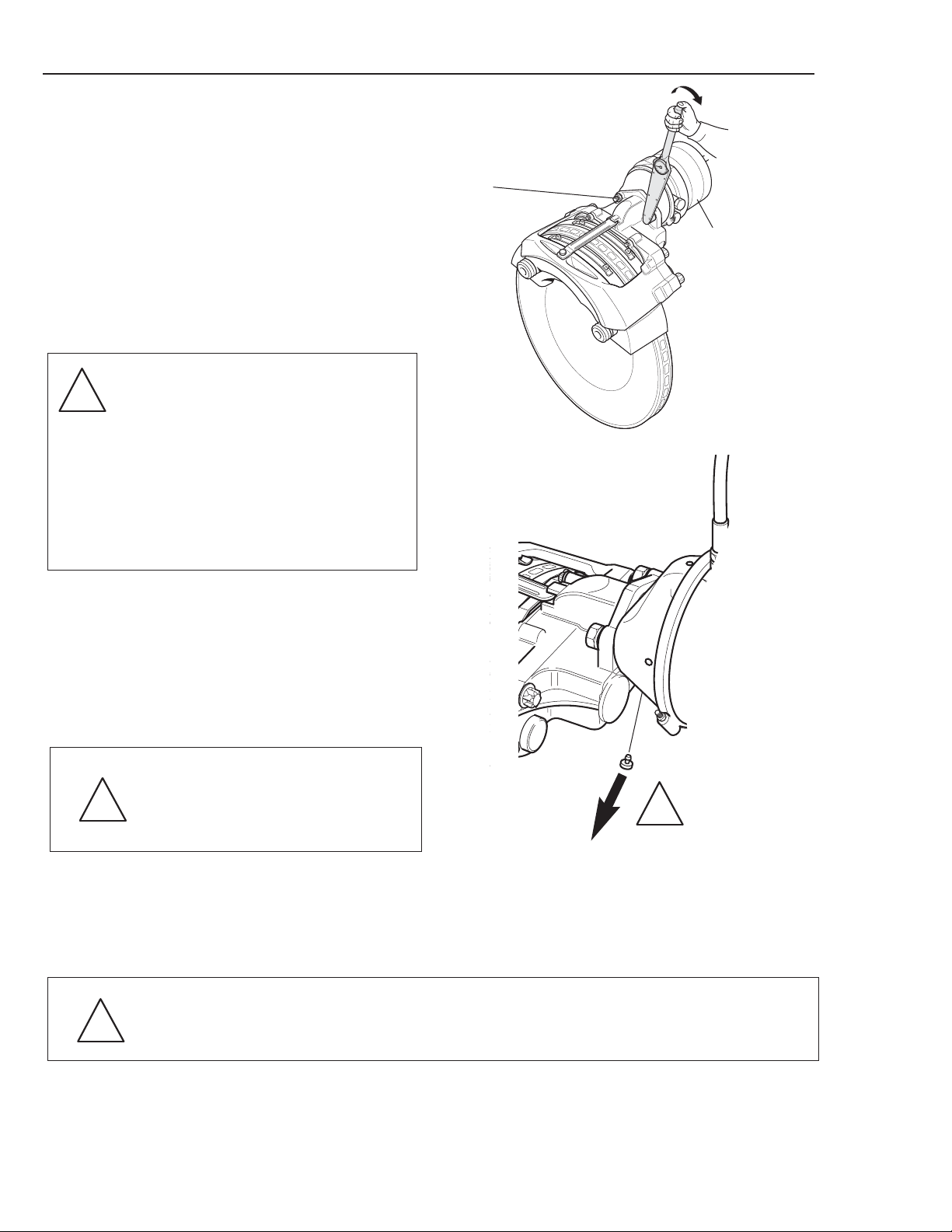
Removing brake chamber
Thoroughly clean the joint faces of brake chamber (25)
and caliper assembly (2) to insure that dirt does not get
into the mechanism area when removing the brake
chamber.
Remove the hose (A). Remove the two fixing bolts (27)
holding the brake chamber (25). Remove the brake
chamber (25).
▼
▼
A
27
25
IMPORTANT!
Follow the ‘General Instructions’ on page 11 and the vehicle manufacturer’s
instructions.
Follow the vehicle manufacturer’s instructions to chock the wheels on an axle
which is not to be raised.
Lift the axle, support and remove the wheels in accordance with the vehicle
manufacturer’s instructions.
Check through the pushrod opening in the brake
chamber attachment flange for moisture/corrosion.
If present, replace the caliper housing complete
with mechanism to avoid operating problems.
If action is required see section on ‘Replacing
caliper housing’.
2
Do not loosen theTorx bolts (78) that hold the caliper housing (2a) and caliper
bridge (2b) together!
Clean the brakes, removing any dirt and dust. Use dust removal equipment or a
vacuum cleaner but do not use compressed air - inhaling dust particles may be
harmful to your health! See ‘Cleaning’ for instructions.
!
!
!

P/N 89652
Installing brake chambers
Check that the new brake chamber (25) is of the correct
design.
NOTE: Failure to use proper brake chamber will affect service life and void caliper warranty.
There must be an internal boot (A) on the push rod. Check
the external seal flange (B) so it is intact and seats correctly!
Install the pipe fitting to the new brake chamber (25).
Check that the brake chamber (25) mating flange on the
caliper is free from dirt and that the inner boot (A) in the
chamber is correctly seated at (B).
Put a dab of grease P/N 89652 or equivalent in the ball cup
in lever (44).
Fit the new brake chamber (25) with fixing bolts (27).
Tightening torque 118-148 ft. lbs. (180±20 Nm)
B
▼
A
25/26
27
118-148 ft. lbs.
(180±20 Nm)
Replacing brake chamber
39

Replacing brake chamber
40
It is important to remove the
lowest drain plug in the chamber
housing if equipped.
Other drain plugs can remain in
position in the chamber housing.
If all the plugs remain fitted the
mechanism will not operate
correctly!
!
Connect the brake chamber (25) hose connection (A).
Remove the drain plug that faces downwards from the
brake chamber housing (25) if equipped.
With the service brake applied and where appropriate,
with the parking brake released, check the brake chambers, hoses and connections for leaks and damage.
Install the wheels as per the vehicle manufacturer’s
instructions.
Check that the brake hoses do not rub during full wheel articulation.
Check the wheel so it turns freely with the parking
brake released.
Remove the axle support and the wheel chocks
and lower the axle in accordance with the vehicle
manufacturer’s instructions.
NOTE!
Check that the contact surface of the rim and hub
are clean and free from distortion. Follow the vehicle manufacturer’s instructions for fitting and
tightening torques!
If changing wheels and/or valve stem, check with vehicle OEM for suitable wheel
and/or valve stem configurations.
!
!
!

26
Removing spring brake chamber
Clean carefully the joint faces of spring brake chamber (26) and caliper assembly (2).
Activate the spring caging mechanism of the brake
chamber so that the spring is held in its compressed
position. See the vehicle manufacturer’s instructions.
Replacing spring brake chamber
For number references shown within parenthesis that do not appear in this section, see the exploded
view (p. 3-4)
Do not loosen the Torx bolts (78) that hold the caliper housing (2a) and caliper
bridge (2b) together!
Clean the disc brake, removing any dirt and dust. Use dust removal equipment or
a vacuum cleaner but do not use compressed air - inhaling dust particles may be
harmful to your health! See ‘Cleaning’ for instructions.
IMPORTANT!
Follow the ‘General Instructions’ on page 11 and the vehicle manufacturer’s
instructions.
Follow the vehicle manufacturer’s instructions to chock the wheels on an axle
which is not to be raised.
Lift the axle, support and remove the wheels in accordance with the vehicle
manufacturer’s instructions.
Replacing spring brake chamber
41
!
!
!
B
Replacing spring brake chamber
42
27
26
B
A
P/N 89652
Insure air line has no pressure (parking brake
applied).
Mark and remove the hose connections of the
service brake (A) and parking brake (B).
Remove the two nuts (27) holding spring brake
chamber (26).
Remove spring brake chamber (26).
▼
A
25/26
Check through the pushrod opening in the brake
chamber attachment flange for moisture/corrosion. If
present, replace the caliper housing complete with
mechanism to avoid operating problems.
If action is required see section on ‘Replacing Caliper
Housing’.
Installing spring brake chamber
Check that the park brake spring is caged in accordance with the manufacturer’s instructions and that
the new spring brake chamber (26) is of the correct
design.
NOTE! Failure to use proper brake chamber will
affect brake function service life and will cause
improper function to no function.
There must be an internal boot (A) on the push rod.
Check the external seal flange (B) so it is intact and
seats correctly!
Install the pipe fittings to the new brake chamber (25).
Check that the disc brake’s connection flange is free
from dirt.
Put a dab of grease P/N 89652 or equivalent in the ball
cup in lever (44).
2
27
26
118-148 ft. lbs.
Install the new spring brake chamber (26) with nuts
(27). Tightening torque 118-148
ft. lbs. (180±20 Nm)
Fit the spring brake chamber (26) hose connections.
NOTE! Do not mix up the hoses!
Remove the drain plug that faces downwards from the
brake chamber (25) housing, if equipped.
Release the parking brake and disengage the spring
brake chamber’s caging mechanism so that the spring
is released.
It is important to remove the lowest
drain plug in the chamber housing,
if equipped.
Other drain plugs can remain in
position in the chamber housing.
NOTE! If all the plugs remain
installed the brake will not operate
correctly!
With the service brake applied and where
appropriate, with the parking brake released, check
the brake chambers, hoses and connections for leaks
and damage.
Fit the wheels as per the vehicle manufacturer’s
instructions.
Check that the brake hoses do not rub during full wheel articulation.
Check the wheel so it turns freely with the parking
brake released.
Remove the axle support and the wheel chocks
and lower the axle in accordance with the vehicle
manufacturer’s instructions.
If changing wheels and/or valve
stem, check with vehicle OEM
for suitable wheel and/or valve
stem configurations.
NOTE!
Check that the contact surface of the rim and hub
are clean and free from distortion. Follow the
vehicle manufacturer’s instructions for fitting and
tightening torques!
Replacing spring brake chamber
43
!
!
!
!

Replacing radial seal and adjustment shaft
44
Replacing radial seal (69) and
adjustment shaft (55)
Grip the 8mm hexagonal end of the adjustment shaft
(55) with suitable handgrips and pull out the adjustment shaft. The radial seal (69) will come out at the
same time. If necessary, pry against the handgrips to
remove the adjustment shaft.
Remove the radial seal (69) from the adjustment shaft
(55).
Check for cracks and/or damage. If the end is broken
off, it is necessary to remove the caliper assembly (2)
from the axle. Use a magnet to retrieve the broken end
from the adjuster mechanism (4).
Clean the adjustment shaft (55) and the area behind
the radial seal (69) inside the caliper housing (2a) and
lubricate with grease P/N 89652 or equivalent.
Lubricate a new radial seal (69) and adjustment shaft
(55) with grease P/N 89652 or equivalent.
NOTE! Correct direction of fitting is important –
see diagram
Tap in the radial seal (69) and adjustment shaft (55)
using special tool P/N 89780.
Continue with the instructions in the ‘Initial setting’
section.
55
69
55
69
69
55
NOTE! Directon of fitting!
P/N 89780

Troubleshooting
Symptoms
NOTE! Follow ‘General Instructions’ Section and the vehicle manufacturer’s
instructions!
• Replace the pads.
• Carry-out initial adjustment + perform function checks.
• Replace the brake disc (See vehicle manufacturer’s
instructions.)
• Take actions in accordance with vehicle manufacturer’s
instructions.
• Remove the drain plug located at the lowest point.
No or low braking effect
• Are the pads worn/below minimum thickness?
• Is pad/disc clearance OK?
• Is the brake disc OK?
• Is air pressure in the brake chamber OK?
(Measure with a pressure guage at the brake chamber)
• Has the drain plug been removed from the brake
chamber housing?
Action
!
• See the vehicle manufacturer’s instructions for troubleshooting
air system.
• See the vehicle manufacturer’s instructions for troubleshooting
air system.
• Carry-out initial adjustment + perform function checks.
• Remove the brake pads, clean the pads, carrier and caliper.
• Replace slide pins/bushings.
• See the vehicle manufacturer’s instructions for information.
• Remove the drain plug located at the lowest point.
Troubleshooting
45
Symptoms
Action
Brakes drag or do not release completely.
• Does air pressure remain in the brake chamber when
the brakes are released?
• Are all of the spring brake chambers released when
the parking brake is off?
• Is pad/disc clearance OK?
• Can the pads move freely in the carrier?
• Is the caliper slide function OK?
• Is the wheel bearing clearance OK?
• Has one of the drain plugs been removed from the
brake chamber housing?

Troubleshooting
46
Troubleshooting
Symptoms
NOTE! Follow ‘General Instructions’ Section and the vehicle manufacturer’s
instructions!
The vehicle pulls to one side
• Are the pads worn on one side of the vehicle?
• Is pad/disc clearance OK?
• Can the pads move freely in the carrier?
• Is pressure the same in both brake chambers of the axle
during braking? (Measure with pressure guage at the
brake chambers.)
• Has one of the drain plugs been removed from the brake
chamber housing?
Action
• Replace the pads.
• Carry-out initial adjustment + perform function checks.
• Remove the brake pads, clean the pads, carrier and caliper.
• See the vehicle manufacturer’s instructions for troubleshooting
air system.
• Remove the drain plug located at the lowest point.
• Remove the brake pads, clean the pads, carrier and caliper.
• See ‘Installing disc brake’ on page 23.
• See ‘Condition of brake rotor’ section on page 16.
• See ‘Lateral runout’ section on page 15.
!
Symptoms
Action
Noise/ vibrations from the brake
• Can the pads move freely in the carrier?
• Are the disc brake and its components attached to
axle as specified?
• Are there non-permitted cracks/grooves on the brake
disc?
• Is the brake disc’s runout within specified parameters?

47
Tools
Tools
Special tools for Haldex disc brake.
For number references in parenthesis in the text which do not appear in this section, refer to the
exploded view (p. 3-4)
Contents of tool kit Haldex P/N 81918.
Part No.
P/N 81918 Complete tool kit including toolbox.
P/N 81920 Slide hammer (puller) for pads (5).
P/N 81921 Expansion drift for slide bushing (14).
P/N 81922 Tool for fitting seal to slide pins (13) in caliper assembly (2).
P/N 87833 Tool for fitting seal to adjuster screw (35) in cover.
P/N 89778 Tool for fitting seal to adjuster screw (35) in cover.
P/N 89779 Tool for fitting seal to adjuster screw (35).
P/N 81927 Protective cover for brake chamber opening in caliper assembly (2).
P/N 81928 Support plug (used in conjunction with P/N 87833), and tool for fitting radial seal (69) to
adjustment shafts (55).
P/N 89780 Tool for fitting radial seal (69) to adjustment shafts (55).
P/N 81919 Toolbox.
P/N 81933 Torx E18 socket for slide pin attaching bolts (10).
P/N 89781 Torx E10 socket for bolts Torx (18) for adjuster mechanism (4).
P/N 89936 Tool for fitting thrust plate clips (29).
P/N 90797 Torx E20 socket for Torx bolts (78) for caliper assembly (2), DB 19
P/N 90798 Torx E24 socket for Torx bolts (78) for caliper assembly (2), DB 22
P/N = Part Number

Tools
Tool kit P/N 81918
81920
81921
81922
87833 81933
81927
81928
87857
89778
89779
89781
89780 89936
P/N 81918
81919
90797
90798
48

Commercial Vehicle Systems
North American Sales
Haldex Brake Products Corporation
10707 N.W. Airworld Drive
Kansas City, MO 64153-1215
Phone: (816) 891-2470
Fax: (816) 801-4198
North American Sales
Haldex Limited
525 Southgate Drive, Unit 1
Guelph, Ontario CANADA N1G 3W6
Phone: (519) 826-7723
Fax: (519) 826-9497
www.haldex.com · www.hbsna.com
8/06 5M GOR L30039
 Loading...