

Hakuba PMD2, PMD1 User Manual
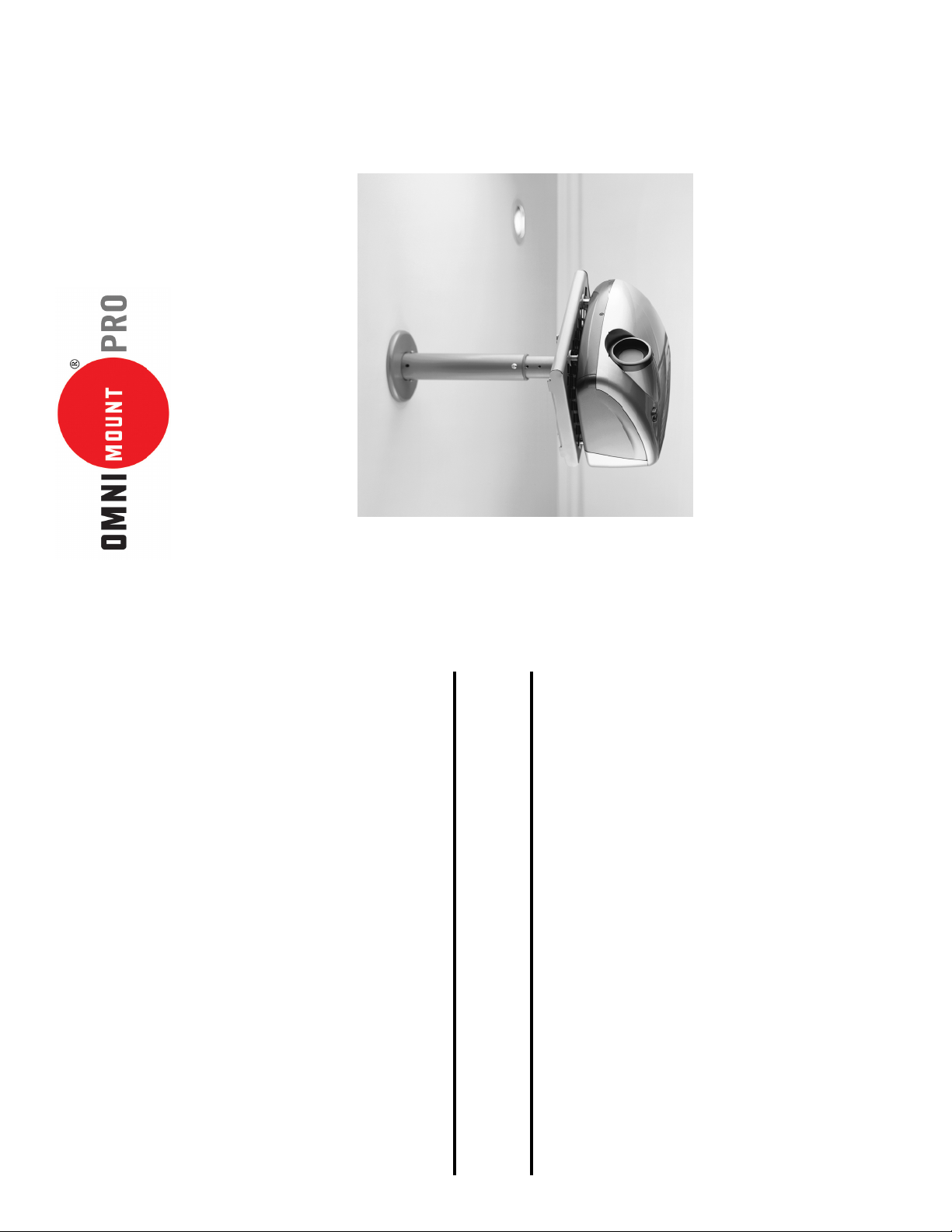
Universal Mounting Grid
Superior Mounting Flexibility
Adjustable Ceiling Pipe Drop
Questions? 1-800-MOUNT IT
User Friendly Adjustments
Installation Instructions
PMD1 PRO & PMD2 PRO:
Universal Projector Mounts
IMPORTANT: To utilize the PMD projector mount, the projector must have
mounting lands (threaded inserts) on the base. Contact OmniMount if you have any
questions regarding the proper installation of this projector mount system.
P/N 1002342—Rev. B 8/2004
OmniMount Systems, Inc.
1-800-MOUNT-IT • www.omnimount.com
8201 South 48th Street • Phoenix, AZ 85044-5355
Thank you for purchasing an OmniMount product.
Warranty: Limited Lifetime on manufacturing defects and workmanship.
Specifications are subject to change without prior notice. Every effort has been made to provide accurate and error-free assembly and installation.
OmniMount Systems disclaims liability for any difficulties arising from the interpretation
of information contained in these instructions. If OmniMount products are used for pur-
poses other than their original intent, OmniMount, its distributors and retailers shall not
be held responsible or liable for injuries or property damage, direct, indirect, or conse-
quential, which may arise from the inability to use this product safely, properly, and in the
manner for which it has been designed and manufactured. Warranty does not apply to
products which have been lost, damaged by misuse, abuse, or accident.
8
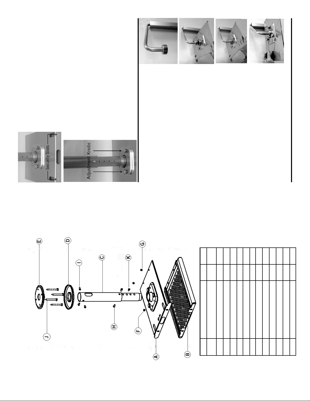
Important: Always secure projector plates by installing 3/8”
Fig. 14
screws (G) into holes on front edge of plates.
Additional security can be provided by installing small pad-
locks through security slots at the rear of the projector plates.
(Fig. 12)
Attach cables to the projector. Turn projector ON, and make pitch
and keystone adjustments as per the projector manufacturers
instructions. For additional pitch/tilt, use the three adjustment
knobs on top of the PMD mount (Fig. 13).
Fig. 15
Fig. 16
Fig. 17
Fig. 13
Fig. 12
Wall Mounting with OmniMount PMD-WM
Install the OmniMount PMD-WM wall mount to the wall as per
the instructions. (Fig. 14)
sliding them apart. (Fig. 2) Loosely thread top projector mounting plate (A) onto threaded
Separate top and bottom projector mounting plates (A&B), by
portion of wall mount coupler. (Fig. 15 & 16)
Thread ¼” hex head set screw (F) into side of pipe collar, on top
projector mounting plate (A). (Fig. 17)
Note: If necessary, screw in tilt knob to gain access to the set
screw hole.
Position top projector mounting plate into desired orientation
(horizontal or vertical), and then tighten set screw (F). Proceed to Step 4 to complete the installation.
7
ware
Mount Assembly Hard-
Part Description Qty.
Models: PMD 1 & PMD 2
C Pipe Drop Assembly 1
A Top Projector Plate 1
B Bottom Projector Plate 1
D Plastic Cover 1
F Hex Screw: ¼”-20 X ¼” 1 (d)
E Ceiling Plate 1 Bag
I Hex Screw: ¼”-X ½” 6 (d)
G Screw: ¼”-20 X 3/8” 2 (c)
H Hex Screw: ¼”-X 5/8” 4 (d)
J Lag Bolt: 5/16” X 3” 4 (e)
Hex Wrench 1 (d)
K Plastic Plugs 14 (b)
2
 Loading...