


Cleaning Technology · Municipal Technology
Scrubmaster B175 R (7180)
Operating Manual
Part number 88-10-3115 - 3922-xx
Valid as from: 04.2018

Introduction
Introduction
Foreword
Dear Customer,
We are certain that the excellent qualities of the machine will justify the faith
you have shown in us by your purchase.
To guarantee safe working with the machine, please read the Safety Notes
chapter before putting it into service.
Your own safety, as well as the safety of others, depends essentially on your
ability to control the vehicle. Please read this original operating manual
before you use the vehicle for the first time, act accordingly and keep these
instructions for future reference or subsequent users. The operating manual
contains all important information for operation, maintenance and care. We
have provided the places in this operating manual concerning your safety with
a danger pictogram. Your authorised Hako dealer is available at all times to
answer further questions about the vehicle or the operating manual.
We would expressly advise you that no legal claims may be asserted based
on the contents of this operating manual. In the case of necessary repair
work, please make sure that only original spare parts are used. Spare parts
must be original spare parts to guarantee safety. We reserve the right to make
changes in the interests of further technical development.
Hako GmbH
23843 Bad Oldesloe, Germany
Hamburger Str. 209-239
Phone +49 4531 806-0
Issue:
Index Book number Change no. Valid as from:
0 88-10-3115 3922-00 04.2018
2 00-7180-00.fm

Introduction
Intended use
Scrubmaster B175 R is a scrubber-drier for the wet cleaning of hard indoor
floor surfaces. This machine is intended for commercial use, e.g. in shopping
centres, swimming pools, shops, airports, schools and hotels. Any use extending beyond this is not intended use. The manufacturer is not liable for any damage resulting from this and the user alone bears the risk. Intended use also
includes compliance with the operating, maintenance and servicing conditions
specified by the manufacturer.
The Scrubmaster B175 R may be used, maintained and repaired only by
persons who are familiar with this work and instructed about the dangers.
The relevant accident prevention regulations as well as the other generally
recognised safety engineering and occupational medical rules must be
complied with.
The machine corresponds by virtue of its design and construction as well as in
the version distributed by us to the usual health and safety requirements of the
EC Directives (see Declaration of Conformity). This declaration loses its validity
in the event of a modification to the machine not authorised by us. The manufacturer is not deemed liable for any damage resulting from unauthorised modifications to the machine.
Notes on warranty
The terms defined in the purchase agreement apply. Claims for compensation
in relation to damage are excluded from the terms of the warranty when the
damage is the result of the failure to observe rules concerning servicing and
maintenance. Maintenance work must be carried out by an authorised Hako
service workshop and confirmed in the “Maintenance Report”, which serves as
a warranty logbook.
The following are excluded from the terms of warranty: wear and tear through
overuse, defective fuses, improper handling and use and unauthorised modifications. Claims under the terms of the warranty are also annulled when damage occurs to the machine resulting from the use of parts or accessories not
explicitly approved of by us or from failure to observe maintenance rules.
00-7180-00.fm 3

Introduction
Acceptance of the machine
Inspect the machine immediately on delivery for signs of transport damage.
You will be compensated for transport damage provided you immediately have
the damage confirmed by the transport company and send in the damage report together with the consignment note to us.
Machine data
Your machine is described clearly by the following data. Please always quote
these data in correspondence or when making a telephone query to your
authorised Hako dealer or our company.
• Machine type
• Manufacturing no.
• Start-up on:
Your nearest authorised Hako dealer:
• Address:
• Telephone:
4 00-7180-00.fm

Table of contents
1 Safety instructions ......................................................... 8
1.1 Warning and danger symbols ......................................... 8
1.2 General safety instructions ............................................. 9
1.3 Operating safety instructions ........................................ 10
1.4 Maintenance instructions .............................................. 11
1.5 Information about special risks ..................................... 12
1.6 Environmental protection instructions and disposal ..... 14
1.7 Labels on the machine ................................................. 15
2 Operation....................................................................... 18
2.1 Overviews ..................................................................... 18
2.1.1 Front view ..................................................................... 19
2.1.2 Rear view ...................................................................... 21
2.1.3 Control panel ................................................................ 22
2.2 Controls and display elements ..................................... 24
2.2.1 Control panel ................................................................ 24
2.3 Multifunction display (MFD) .......................................... 29
2.3.1 Menu guidance ............................................................. 29
2.3.2 Main menu .................................................................... 30
2.3.3 Sub-menu ..................................................................... 36
2.3.4 Controls at the machine ................................................ 40
2.4 Functional description: .................................................. 42
2.4.1 Solution tank ................................................................. 42
2.4.2 Rotating brush and roller brush unit ............................. 43
2.4.3 Side brush unit .............................................................. 43
2.4.4 Wiper ............................................................................ 43
2.4.5 Squeegee ..................................................................... 44
2.4.6 Waste water tank .......................................................... 44
2.4.7 Suction turbine .............................................................. 44
2.4.8 Travel drive ................................................................... 45
2.4.9 Brakes .......................................................................... 45
2.4.10 Batteries ....................................................................... 45
3 Operation....................................................................... 46
3.1 Instruction ..................................................................... 46
3.2 Before putting into service ............................................ 46
3.3 Check list: Before machine start-up .............................. 47
3.3.1 Installing the mains cable ............................................. 47
3.3.2 Driver's seat .................................................................. 48
3.4 Cleaning ....................................................................... 50
88-00-3115-01IVZ.fm 5

Table of contents
3.4.1 Fleet-Recorder (option) ................................................ 51
3.4.2 On-board dosing system (option) ................................. 52
3.4.3 Useful cleaning tips ...................................................... 53
3.4.4 Handling and braking the vehicle ................................. 54
3.4.5 Pushing the machine .................................................... 55
3.4.6 Turning off the machine ................................................ 56
3.4.7 Check list: After cleaning .............................................. 56
3.5 Loading and transporting .............................................. 57
3.6 Service information ....................................................... 58
4 Technical data............................................................... 61
5 Maintenance and Servicing ......................................... 64
5.1 Maintenance certificate ................................................. 65
5.2 Maintenance plan ......................................................... 66
5.3 Battery .......................................................................... 69
5.3.1 Checking the charging state ......................................... 69
5.3.2 Charge the battery ........................................................ 70
5.3.3 Checking the acid level ................................................. 74
5.3.4 Replacing the battery .................................................... 75
5.3.5 Battery plug coding ....................................................... 76
5.3.6 Maintaining drive batteries ............................................ 77
5.3.7 Taking the machine out of service for a long period ..... 77
5.3.8 Disposing of batteries ................................................... 77
5.4 Solution tank ................................................................. 78
5.4.1 Filling the solution tank ................................................. 78
5.4.2 Emptying the solution tank ........................................... 80
5.4.3 Cleaning the solution tank ............................................ 80
5.5 Waste water tank .......................................................... 81
5.5.1 Emptying the waste water tank ..................................... 81
5.5.2 Cleaning the waste water tank ..................................... 82
5.5.3 Cleaning the coarse dirt sieve ...................................... 83
5.5.4 Cleaning the intake sieve ............................................. 83
5.5.5 Checking the seal at the drain valve ............................. 83
5.5.6 Cleaning the fresh water filter ....................................... 84
5.5.7 Checking the seal in the tank cap ................................. 84
5.6 Rotating brush unit ....................................................... 85
5.6.1 Replacing the brushes/pads ......................................... 85
5.6.2 Cleaning the brushes .................................................... 85
5.6.3 Ejecting the brushes/pads ............................................ 86
5.6.4 Coupling the brushes/pads ........................................... 86
5.7 Roller brush unit ........................................................... 87
6 88-00-3115-01IVZ.fm

Table of contents
5.7.1 Emptying the dirt hopper .............................................. 87
5.7.2 Replacing the brushes .................................................. 88
5.7.3 Cleaning the brushes .................................................... 88
5.7.4 Disassembling the brushes .......................................... 88
5.7.5 Installing the brushes .................................................... 88
5.8 Side brush unit (optional) .............................................. 89
5.8.1 Adjusting the side brush ............................................... 89
5.8.2 Changing the side brush ............................................... 90
5.9 Squeegee ..................................................................... 91
5.9.1 Cleaning the squeegee ................................................. 91
5.9.2 Changing the sealing / slot strip ................................... 93
5.9.3 Adjusting the sealing strips ........................................... 94
5.10 Wiper ............................................................................ 96
5.10.1 Changing the wiper rubber ........................................... 96
6 Attachments/options.................................................... 97
6.1 Spray suction tool ......................................................... 97
6.2 Manual suction tool: ...................................................... 98
6.3 Spray nozzle ................................................................. 99
EC Declaration of Conformity ................................. 101
88-00-3115-01IVZ.fm 7

Safety instructions
1 Safety instructions
1.1 Warning and danger symbols
Important tasks concerning the safety of the operator and machine are named
as follows in this operating manual and emphasised by symbols.
Danger
Indication of a direct danger with high risk, in which death or severe
physical injury can occur if it is not avoided.
Warning
Indication of a possible danger with average risk, in which death or
severe physical injury can occur if it is not avoided.
Caution
Indication of a danger with low risk, in which light to medium severe
physical injury or material damage can occur if it is not avoided.
Attention
Attention indicates a hazard that can lead to technical damage when
not observed.
Environmental danger
Environmental danger due to the use of substances from which a
health and environmental risk proceeds.
Note
Indication of information that facilitates more effective and economical use of the machine.
8 01-7180-00.fm

Safety instructions
Note
Before starting up the machine, read the following safety instructions
and act accordingly. Machine operating errors can be avoided and
trouble-free operation can be guaranteed only with precise factual
knowledge.
1.2 General safety instructions
• Apart from the instructions in this operating manual, the general safety and
accident prevention regulations of the legislation must be taken into
account.
• Before the machine is put into service, please carefully read the operating
manual you receive as well as further separate instructions for additional
implements or attachments and observe them in all aspects of your work.
• The machine may be used, maintained and repaired only by persons who
have been instructed by Hako experts.
• The machine is not intended for use by persons (including children) with
reduced physical, sensory or mental capabilities or by persons lacking the
required experience and knowledge.
• Children should be supervised to ensure they do not play with the machine.
• The operating manual should always be available at the machine's place of
use and should therefore be stored with the machine.
• Please hand over these documents to the new owner/operator on sale or
rental of the device. Have the hand-over confirmed!
• The labels attached to the machine provide important information for safe
operation. Renew labels that are no longer legible or present.
• Only wheels (wheel tyres) approved by Hako may be used.
• With Hako-AntiBac® machine variants, the plastic inner surface of the fresh
water and waste water tanks contains silver ions in nanoparticle form.
• Spare parts must be original spare parts to guarantee safety.
01-7180-00.fm 9

Safety instructions
1.3 Operating safety instructions
Before putting into service
• Before initially starting up the machine, charge the used battery fully and
appropriately with commissioning charge. Please observe the operating
manual of the charger and the operating manual of the battery manufacturer. Hako assumes no liability for battery damage resulting from insufficient commissioning charge.
• Check the machine for operating safety before every start-up! Eliminate
faults immediately.
• Before starting work, the operator must familiarize himself with all
equipment, operating and actuating elements as well as with their function.
It is too late to do this during operation!
During operation
• Sturdy and slip-proof shoes must be worn when working with the machine.
• Only those surfaces approved by the contractor or its authorised representative for use of the machine may be driven on.
• If the machine is used in areas in which objects may fall down, this is only
permitted if it has a roof which protects the driver.
• When working with the machine, pay special attention to third persons,
especially children.
• When driving over thresholds, raise the brush head.
• Only use detergents suitable for automatic machines (foam retarded) and
observe the application, disposal and warning instructions provided by the
detergent manufacturer.
• The machine is not suitable for removing liquids, dusts or materials that are
dangerous to health, combustible or explosive. It is also prohibited to collect
burning objects, e.g. glowing cigarettes. The collection of wood dust, e.g.
beech and oak dust, is also prohibited – health hazard!
• Excessive quantities of dust must be avoided when working with the side
brush unit!
• The machine is not suitable for collecting large quantities of water, e.g. in
the event of flooding.
• For reasons of safety, the driver's seat is equipped with a seat contact
switch. The machine can only be started when the driver is sitting on the
driver's seat. The function of the seat contact switch must not be bypassed.
• The machine must not be used in potentially explosive atmospheres.
• It is not permitted to transport other people or heavy objects.
• When transporting the machine, raise the squeegee and the brush head.
Adjust your way of driving to local conditions.
10 01-7180-00.fm

Safety instructions
• Drive slowly on wet surfaces, particularly in bends, due to the risk of
skidding.
• Drive slowly into the bend when driving downhill.
• For cleaning, the machine must only be used on a level surface with a
maximum slope of 6 %.
• Transport journeys on slopes of up to 10 % must only take place for a
limited period of time and with special caution.
• Manipulating the switches and protective devices is forbidden.
After operation
• Remove the key when leaving the machine to prevent unauthorised use.
• After use, park the machine in a dry, indoor location with the brush head
and squeegee raised.
1.4 Maintenance instructions
• Daily and weekly maintenance work must be done in accordance with the
maintenance plan by the operating staff. In all other maintenance work,
please contact your nearest Hako service centre.
• The maintenance work and maintenance intervals specified in the
operating manual must be complied with.
• Suitable tools and protective clothing such as gloves and safety goggles must
be used during cleaning and maintenance work.
• Have the machine checked for safe condition by an expert in accordance
with the accident prevention regulations at appropriate intervals (we
recommend at least once yearly).
• Spare parts must at least comply with the technical requirements specified
by the manufacturer. This is guaranteed by original spare parts.
• Turn the machine off and disconnect the battery connector when cleaning
and maintaining the machine and before replacing parts.
• To prevent unauthorised use of the machine, remove the ignition key.
• Cleaning the machine with a high-pressure cleaner or steam jet is not
allowed.
• Application of aggressive and corrosive detergents is not allowed.
• After cleaning, let the machine air dry, e.g. over the weekend.
• Only put the machine into service when all the protective devices are
attached and in protection position.
01-7180-00.fm 11

Safety instructions
1.5 Information about special risks
Electrical system
• If the electrical system is faulty, always turn off the machine, disconnect the
battery and eliminate the fault.
• Work on the electrical system may be done only in accordance with
electrical engineering standards by a specialist trained for this work.
• Regularly inspect/check the electrical system of the machine. Defects such
as loose connections, loose nuts of electrified bolts, electrical components
or damaged cables must be eliminated immediately.
• Only use original fuses with the specified current. If stronger fuses are
used, the electrical system can be destroyed and fires may occur.
Batteries
• Observe the operating manuals and safety instructions provided by the
battery manufacturer.
• Never connect or disconnect batteries when the machine is turned on.
• Make sure the batteries are never fully discharged; recharge them as
quickly as possible.
• Only instructed maintenance personnel must handle and replace batteries.
• Only batteries approved by Hako may be used at the intended position.
• Danger! Make sure that the insulation of the battery cables is not damaged.
The battery cables should not rub against anything. If the insulation is
defective, no longer use the machine and have the battery cables replaced
by the Hako customer service immediately.
• Caution! Always make sure that the batteries are clean and dry to avoid
creeping currents and corrosion damage. Protect the batteries, in
particular, against conductive contamination, e.g. metal dust.
• Risk of short circuits and spark formation! Never place tools or other electrically conductive objects on the battery!
• Do not remove insulating caps and covers, if necessary re-install them after
carrying out work on the battery cables.
• Caution! Explosive gases can develop when charging the batteries.
Avoid smoking, fire or naked light in the vicinity of batteries. Ensure sufficient ventilation when charging the batteries.
• For further safety instructions, see Hako supplementary sheet 88-60-2556
– information for drive batteries.
Power connection and mains plug
• Only connect the machine to an electrical connection installed by an
electrician in accordance with IEC 60364-1.
• We recommend connection to a fused socket with a residual current circuit
breaker (max. 30 mA).
12 01-7180-00.fm

Safety instructions
• We recommend use of splash water protected sockets according to
DIN VDE 0620-1.
• Make sure the socket is dry!
• Only touch the mains plug and the mains cable with dry hands.
• Never insert the mains plug into the socket when the floor is wet or damp.
• Never dip the mains cable or mains plug in water or other liquids or clean it
under running water.
• Damp mains plugs or mains plugs that have become wet must no longer be
used. Water can enter the mains plug. Only qualified electricians must carry
out recommissioning.
• Check the mains cable regularly for damage. If damage is detected, the
machine must no longer be used. Have a qualified electrician replace the
mains cable.
• Make sure that no water or liquid can come into contact with live parts of
the machine. If water has still entered parts, immediately disconnect the
mains plug and have the machine checked by the authorised Hako service.
01-7180-00.fm 13

Safety instructions
1.6 Environmental protection instructions and disposal
If the end of use of the machine or of its components is reached and this is
handed over for scrapping, the components must be correctly disposed of.
Further information about disposal is available through the competent local
authorities and the authorised Hako dealers.
Do not dispose of products with this symbol in domestic waste.
Disposal takes place through local collecting points or the
manufacturer.
Recycle used materials with this symbol according to their labelling and do not dispose of them in domestic waste.
• Observe the applicable laws and local regulations when disposing of dirt,
waste water and detergents, also see the German Water Resources Law
(WHG).
• Used batteries with the recycling symbol contain reusable commodities. In
accordance with the symbol showing the crossed-out garbage bin, these
batteries must not be disposed of in the domestic waste. Return and
recycling have to be arranged with the authorised Hako dealer as required
in § 6 and § 8 of the German battery law (BattG)!
14 01-7180-00.fm

Safety instructions
A
B
Fig. 1:
1
2
3
E
A
C
B
C
D
D
F
E
F
1.7 Labels on the machine
The following safety and instruction labels are affixed to the machine in a
clearly visible and legible manner.
Attention
Renew missing or illegible labels immediately!
01-7180-00.fm 15

Safety instructions
H
Fig. 2:
I
G
I
H
J
G
J
A
16 01-7180-00.fm

Safety instructions
Company logo label Fig. 1/Fig. 2-A
The Hako logo is located at the front on the steering column and at the rear on
the hopper.
Label
– Read and observe the operating manual Fig. 1-B1
– Maximum permissible slope 6 % when cleaning Fig. 1-B2
– Never clean the machine with a high-pressure cleaner Fig. 1-B3
The label is located on the left hand side next to the driver's seat.
Label – Maintenance parts (yellow dot) Fig. 2-C
The yellow dot is located on the cover of the fresh water filter.
Label – Type plate Fig. 2-D
The type plate is located in front of the left front wheel.
Label – Explosive gases Fig. 1-E
The label is in the battery compartment.
Label – 36 V Fig. 1-F
The label is in the battery compartment.
Label – QR code Fig. 2-G
The label is located on the control panel.
Label – Drain waste water Fig. 2-H
The label is located on the drain hose of the waste water tank.
Label – Drain fresh water Fig. 2-I
The label is located on the drain hose of the solution tank.
Label – Keep off! Fig. 2-J
The label is located on the rotating brush or roller brush unit.
01-7180-00.fm 17

Operation
19
21
10
3
Fig. 3:
1718 16 15 14 13
4
9
11
12
8
7
6
5
2 Operation
2.1 Overviews
The description in chapter 2 contains information on the function and handling
of the individual controls on the machine. The controls always have the same
item number in all chapters.
18 02-7180-00.fm

2.1.1 Front view
Item Designation
1
2
3
4
5
6
7
8
9
10
11
12
13
14
15
16
17
18
19
Steering wheel
Driver's seat
Tray
Flashlight on a pole
Key for electronic system cover
Key for side panelling
Holder for manual suction tool or manual spray suction tool
Drinks holder and storage compartment
Socket for USB connection
Side panelling
Ball cock
Fresh water filter
Wiper
Side brush unit
Collision protection
Working light
Operating brake
Travel drive
Warning device
Operation
02-7180-00.fm 19

Operation
19
32
33
28
Fig. 4:
34
22
20
21
23
24
29
30
31
2527 26
35
36
37
38
39
42
40
20 02-7180-00.fm

2.1.2 Rear view
Item Designation
20
21
22
23
24
25
26
27
28
29
30
31
32
33
34
35
36
37
38
39
40
41
Mains cable
Accelerator pedal
On-board dosing system
Brush unit
Wiper
Solution tank
Maintenance opening solution tank
Squeegee water connection
Fresh water drain hose
Squeegee
Suction hose
Drain hose waste water
Waste water tank maintenance opening
Water connection
Spray nozzle
Battery compartment
Battery connector
Coarse dirt sieve
Waste water tank
Intake sieve
Filling opening
Automatic filling unit
Operation
02-7180-00.fm 21

Operation
46
48
51
Fig. 5:
45
47
49
58
53
55
42
59
52 5054
56
57
43 44
2.1.3 Control panel
Item Designation
42
Multifunction display (MFD)
43
Return button
44
Turn-push knob
Button – brush unit
45
Button – squeegee
46
Button – fresh water supply
47
Button – boost function
48
Button – on-board dosing system
49
22 02-7180-00.fm
Button – brush unit and squeegee
50
Button – driving direction selection
51

Button – I-Button Reader, Fleet-Recorder Standard
52
Key switch
53
Button – signal horn
54
Button – speed reduction forwards gear
55
Button – silent operation
56
Button – tool operation
57
Button – pre-sweep suction unit
58
Button – side brush unit
59
Operation
02-7180-00.fm 23

Operation
A
B
2.2 Controls and display elements
2.2.1 Control panel
The individual functions of the buttons on the control panel are described
below. The respective activated functions are visible as corresponding symbols in the multifunction display (MFD).
Key switch Fig. 5-53
The electrical system is switched on and off with the key switch.
• Position 0: The electrical system is switched off. The key can be pulled out.
• Position 1: The electrical system is switched on.
• The software version is displayed for approx. 1 second on the MFD,
followed by the last service code for approx. 3 seconds if necessary. The
operating hours meter is then displayed.
Driving direction selection button Fig. 5-51
The driving direction is selected with this button. The driving direction can be
changed while driving.
• Push the button (A): Forwards gear
• Push the button (B): Reverse gear
Note
A warning signal is output when in reverse gear. The maximum
speed when reversing is half of the maximum speed when driving
forwards.
24 02-7180-00.fm

Operation
Speed reduction button Fig. 5-55
The maximum speed when driving forwards is reduced by approx. 50 % with
this button.
• Push the button: Speed reduction ON
• Push the button again: Speed reduction OFF
Signal horn button Fig. 5-54
The signal horn is switched on and off with this button.
• Push the button: Signal horn ON
• Release the button: Signal horn OFF
Fresh water supply button Fig. 5-47
The fresh water supply is switched on and off with this button.
• Push the button: Fresh water supply ON
• Push the button again: Fresh water supply OFF
Boost function button Fig. 5-48
In order to remove heavy contamination, it is possible to boost the scrubbingvacuuming cleaning program (green button Fig. 5-50) and scrubbing (button
Fig. 5-45) using the boost function.
• Push and hold the button: The highest level of fresh water dosing and the
increased brush pressure are activated simultaneously.
• Release the button: The machine switches back to the operating mode it
was in before the boost function.
02-7180-00.fm 25

Operation
Brush unit button Fig. 5-45
The brush unit is lowered and raised with this button.
• Push the button: The brush unit is lowered. When actuating the accelerator
pedal, the brush drive and the water supply are switched on.
• Push the button again: The brush drive and the water supply are switched
off. The brush unit is raised.
Note
If the accelerator pedal is not actuated, the brush drive and the water
supply are switched off.
Squeegee button Fig. 5-46
The squeegee is lowered/raised and the suction turbine switched on and off
with this button.
• Push the button: The squeegee is lowered and the suction turbine switched
on.
• Push the button again: The squeegee is raised. After an after-run time of
approx. 15 seconds, the suction turbine is switched off.
Note
The squeegee is automatically raised when reversing. The suction
turbine drive remains switched on.
26 02-7180-00.fm
Operation
Button – on-board dosing system Fig. 5-49
The dosing system for the detergent is switched on and off with this button.
• Push the button: Dosing system ON
• Push the button again: Dosing system OFF
Brush unit and squeegee button Fig. 5-50
The brush and suction turbine drive are switched on and off simultaneously
with this button.
• Push the button: The brush unit, the side brush unit and the squeegee are
lowered, and the suction turbine is switched on. The brush drive and the
water supply are switched on when the accelerator pedal is actuated.
• Push the button again: The brush unit and the side brush unit are raised.
The brush drive and the water supply are switched off. The squeegee
continues to run for approx. 15 seconds to absorb residual water.
Button – Side brush unit Fig. 5-59
The side brush unit is switched on and off with this button.
• Push the button: Side brush unit ON
• Push the button again: Side brush unit OFF
02-7180-00.fm 27

Operation
Button – tool operation Fig. 5-57
The following tools can be switched on and off using this button when the
driver is not on the seat:
• Spray nozzle
• Manual suction or spray suction tool
If the machine does not have a particular tool, it is excluded from the switching
order.
• Push the button: Spray nozzle ON
• Push the button twice: Manual suction and spray suction tool ON
• Push the button again: Tool operation OFF
Button – silent operation Fig. 5-56
The suction turbine is switched to silent operation with this button.
• Push the button: Silent operation ON
• Push the button again: Silent operation OFF
I-Button Reader Fleet-Recorder Fig. 5-52
The I-Button Reader is used to activate the functions.
Red illuminated LED or warning sound after switching on the machine request
the activation of the operating data recording system via the I-Button Key.
• Push the I-Button-Key for approx. 2 seconds against the I-Button-Reader.
The red LED goes out. The machine is ready for operation.
28 02-7180-00.fm

Operation
Fig. 6:
A
B
C D
2.3 Multifunction display (MFD)
The functions and indicators of the machine are set and displayed with the
multifunctional display. After the machine is switched on, the operating system
and data are loaded and the start screen Fig. 6-A appears on the display.
After several seconds the view changes, and the main menu Fig. 6-B
appears. By selecting and confirming the soft key Menu selection Fig. 6-C
you are taken to the sub-menu Fig. 6-D.
Note
It is only possible to switch to the sub-menu if the cleaning functions
are switched off!
2.3.1 Menu guidance
The menu is operated with the turn-push knob Fig. 5-44
Menus and sub-menus are selected in the multifunctional display and the individual menu item values are set or changed with the turn-push knob. The following basically applies:
• Turn to select a menu item. The selected menu item is displayed with a
yellow border.
• Push to activate a menu item.
You can jump back to the previous menu using the return button Fig. 5-43.
02-7180-00.fm 29

Operation
Fig. 7:
A
B
C
2.3.2 Main menu
The main menu is divided up into three levels.
• Status level Fig. 7-A
• Function level Fig. 7-B
• Action level Fig. 7-C
Symbols at status level
Symbol Designation Meaning
Time The current time is displayed in hours and
minutes.
Changes can be made to the time in the
sub-menu.
Service alarm
clock
If the service alarm clock Days has elapsed, this
symbol is permanently visible.
Accelerator
pedal in neutral
This symbol appears when the accelerator pedal
is in the neutral position.
position
Speed reduction The symbol is displayed when the machine is
driving at reduced speed.
Parking brake The symbol is displayed when the parking brake
is activated.
30 02-7180-00.fm

Operation
Seat contact The warning symbol lights up if the driver gets
up from the driver's seat during operation. Main
functions, e.g. scrubbing, vacuuming and driving, are no longer possible.
User The symbol indicates the current user setting.
Silent operation The symbol appears when the machine is work-
ing in reduced-noise operation. The symbol also
appears at the Squeegee symbol.
Operating hours
meter
The operating hours in work mode are
displayed.
The operating hours for the individual units can
be called up in the sub-menu.
Service alarm
clock
If the service alarm clock Operating hours has
elapsed, this symbol is permanently visible.
Service indicator The symbol appears if a service case occurred,
but it had already been eliminated automatically
or by operator intervention.
Service indicator The symbol appears if a service case occurs. An
acoustic warning is also output and a four-digit
service code appears on the right next to the
symbol, see section 3.6
02-7180-00.fm 31
Operation
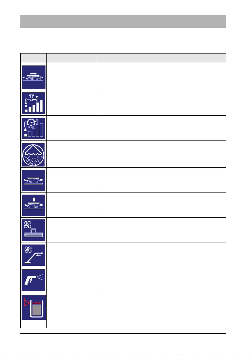
Symbols at function level
All active units are displayed as symbols at function level.
Symbol Designation Meaning
Side brush unit Side brush unit active
Speed-independent water dosing
Speed-dependent water dosing
The selected water dosing is displayed in the
bar diagram.
The selected water dosing is displayed in the
bar diagram.
Water quantity adaptive to driving speed.
On-board dosing
On-board dosing system active
system
Brush unit Brush unit active
Increased brush
pressure
Brush unit operating with increased brush
pressure
Squeegee Squeegee and suction turbines active
Manual suction
Manual suction tool or spray suction tool active
tool/spray suction
tool
Spray nozzle Spray nozzle active
Waste water tank
full warning
symbol
The symbol appears when the waste water tank
is full. An acoustic warning is also output, and
waste water collection is switched off. Empty
the waste water tank immediately, see section
5.5.1.
32 02-7180-00.fm

Symbol Designation Meaning
Solution tank
full
The current filling level of the solution tank is
shown descending in steps of 20 %.
Operation
Warning symbol – solution
tank empty
The symbol appears when the filling level of the
solution tank is approximately 10 litres. A warning
sound is additionally output.
Fill the solution tank immediately, see section 5.4.1
Battery
charging state
The current charge level of the battery is displayed
in steps of 10 %, see section 5.3.1
indicator
Additional symbols
For more information there are additional symbols, which are explained in the
following.
Symbol
Designation
Warning
symbol –
red spanner
Warning
symbol
Meaning
Faults in the functions are signalled by the red spanner. A 4-digit service code is also displayed at the
same time.
If this symbol appears, the unit
• is not installed or
• not configured
Example: On-board metering system not installed.
Symbol OFF If the symbol appears, the function is switched off.
Example: the water supply is switched off.
Function
symbol
displayed in
Interrupted functions are shown in yellow, e.g. if the
accelerator pedal is in the neutral position.
Example: Function interrupted by brush unit.
yellow
Symbol
displayed in
grey
If a symbol appears in grey, the function cannot be
started because the prerequisites for starting have
not been fulfilled.
Example: Switch to sub-menu not possible.
02-7180-00.fm 33

Operation
Fig. 8:
A B GFEDC
H
60
Action level
Settings can be made or actions performed in the action level using soft keys
Fig. 5-A to G.
The soft keys are selected by rotating the turn-push knob (soft key with yellow
border) and confirmed by pressing. An action window opens Fig. 8-H, in
which the actions can be carried out using the turn-push knob.
The following actions are possible:
Soft key Action
Setting
window/
soft key
A
Water
dosing
Depending on the presetting, the action window
appears for speed-dependent or speed-independent
water dosing.
• The water dosing has 5 settings:
• After reaching the highest speed-dependent water
quantity, the speed dependence is deactivated by
turning the turn-push knob clockwise.
B
Brush
pressure
Brush pressure increase ON/OFF
Green background = active
increase
34 02-7180-00.fm

Operation
C
Decoupling the
brushes
D
Coupling
the
brushes
E
Working
light
F
Flashlight
G
Forward
travel
warning
device
Ejecting the brushes, see section 5.6.3
Coupling the brushes, see section 5.6.4
Working light ON/OFF by means of direct selection
using the soft key.
If the working light is switched on, the colour of the
soft key changes from white to green.
Flashlight ON/OFF by means of direct selection
using the soft key.
If the flashlight is switched on, the colour of the soft
key changes from white to green.
The following settings can be selected in the action
window:
• Turn indicator ON/OFF
• Acoustic warning ON/OFF
• Turn indicator and acoustic warning ON/OFF
If the respective function is switched on, the colour
changes from white to green.
02-7180-00.fm 35

Operation
Fig. 9:
B
G
F
E
D
C
A
43
2.3.3 Sub-menu
Configuration can be carried out, operating data read off and the clock/calendar set in the sub-menu. Some sub-menus require additional access rights.
After calling up the sub-menu, the cursor automatically jumps to the operating
hours menu.
To return to the main menu, press
• soft key Home Fig. 9-A or
• the return key on the control panel Fig. 9-43
36 02-7180-00.fm

The following sub-menus can be selected:
Operating hours meter menu Fig. 9-B
• As well as the machine activation time
and work mode, the operating hours of
the individual units are displayed.
• The remaining time until the next
service is displayed in hours/days at
the bottom right. If a service is required,
the spanner appears in red.
Maintenance menu Fig. 9-C
The maintenance menu contains the
following menu items:
•The Maintenance instructions
sub-menu
• Activation/deactivation of speeddependent water dosing
• Activation/deactivation of automatic
squeegee cleaning
The Maintenance instructions sub-menu
opens, in which pictures for daily cleaning
and maintenance are stored.
When this menu is exited, a diskette
appears.
By selecting and confirming the Diskette
symbol, you are confirming that you have
carried out the maintenance.
Operation
Speed-dependent water dosing ON/OFF
Automatic squeegee cleaning ON/OFF,
see section 5.9.1
02-7180-00.fm 37

Operation
Time/date menu Fig. 9-D
User settings menu Fig. 9-E
Time:
• Choice between 12 hour or 24 hour
display
• Set the clock in hours and minutes
Date:
Set the date: day, month and year.
The set values are taken over when the
menu is exited.
The user settings menu contains:
• Selection of:
• Specified settings (1-6)
• User-specific settings (A-C)
• Definition of:
User-specific settings (A-C)
9 settings are available in the selection
menu:
• The specified settings (1-6) contain
predefined standard procedures
• User-specific settings (A-C) contain userdefined function procedures and function
restrictions.
The selected, active user setting is displayed with a number/letter with a green
background.
3 programs (A, B, C) with user-specific settings can be stored in this configuration
menu.
The modification of user profiles requires
additional access rights.
38 02-7180-00.fm

Configuration menu Fig. 9-F
The following settings are made in the configuration menu:
• Activate/deactivate options
• Setting of machine-specific parameters
Making changes to the configuration menu
requires additional access rights.
Service information menu Fig. 9-F
The last 10 items of service information are
displayed in the service information menu.
The operator can perform the following
actions:
• Delete the last service information when
• Obtaining detailed information
Deletion of the last service information
from the display:
Select the Delete symbol with the turnpush knob and press the turn-push knob
for 3 seconds.
The Delete symbol is now no longer visible
and the service code is no longer displayed after starting up the machine.
If the Information symbol appears next to
the service code, detailed information can
be requested.
Select the Information symbol with the
turn-push knob and confirm. Another window opens in which detailed information is
displayed.
Operation
the fault has been remedied
02-7180-00.fm 39

Operation
Fig. 10:
17
20
21
26
28
40
2.3.4 Controls at the machine
Mains cable Fig. 10-20
The mains connection supplies voltage to the on-board charger.
Operating brake Fig. 10-17
When the accelerator pedal is released, the machine comes to a stop due to
the braking effect of the travel drive. If this braking effect is not sufficient, the
operating brake can be applied in addition.
Accelerator pedal Fig. 10-21
The accelerator pedal is used to drive forwards or reverse and continuously
adjust the speed at the same time.
If the accelerator pedal is not actuated, it automatically returns to the zero
position and the machine stops.
Filling opening fresh water Fig. 10-40
The solution tank is filled via the filling opening. If the solution tank is filled
using fast filling, the grey cover can be removed to increase the size of the
filling opening.
Optionally, the solution tank can be filled via the automatic filling unit,
see section 5.4.1.
Fresh water drain hose Fig. 10-28
The solution tank is drained using the drain hose.
Solution tank maintenance opening Fig. 10-26
The cleaning opening is used for cleaning the solution tank.
40 02-7180-00.fm

Operation
Fig. 11:
12
31
10
11
32
Side panelling Fig. 11-10
The trough batteries and the suction turbines are behind the side panelling.
The side panelling can be easily removed using the provided wrench.
Waste water tank maintenance opening Fig. 11-32
The maintenance opening is used to drain the waste water and for cleaning
the tank.
Fresh water filter Fig. 11-12
When supplying water from the solution tank to the brush unit, the fresh water
is cleaned by the filter insert.
Ball cock Fig. 11-11
The ball cock is used to switch the water supply on and off manually in case
the fresh water filter needs to be unscrewed.
Drain hose for waste water Fig. 11-31
The waste water that is collected is drained using the drain hose.
02-7180-00.fm 41

Operation
25
23
Fig. 12:
7
14
40
29
2.4 Functional description:
Scrubmaster B175 R is a ride-on scrubber-drier for wet cleaning hard floor
surfaces. The Scrubmaster B175 R is intended for economical cleaning of
large operational areas.
In cleaning mode, the cleaning solution is supplied from the solution tank to
the rotating brushes in the brush unit. When the machine is moving forwards,
the used waste water is absorbed by the squeegee and conveyed into the
waste water tank.
A seat contact ensures that the machine can only be operated when the operator is sitting on the seat.
2.4.1 Solution tank
The solution tank Fig. 12-25 is filled via the filling opening Fig. 12-40. The
solution tank has a capacity of 175 litres. The current filling level is shown in
the multifunctional display. If the filling level is less than 10 litres in the tank,
the Tank empty symbol appears in the display and an acoustic warning indi-
cates that topping up is required.
42 02-7180-00.fm

Operation
Fig. 13:
A
13
B
2.4.2 Rotating brush and roller brush unit
The brushes in the brush unit Fig. 12-23 are driven by two electric motors.
The brush unit is lowered using the brush unit Fig. 5-45 button. When actuating the accelerator pedal, the brush motors and the water supply are switched
on. The floor is cleaned by the rotating brushes and the supply of cleaning
solution. The brush pressure can be changed in the MFD.
There is an indicator on the brush desk showing the amount of brush wear.
The brushes in the rotating brush unit can be ejected for maintenance purposes by pressing the Brush decoupler Fig. 8-C soft key in the MFD,
see section 5.6.3
2.4.3 Side brush unit
In order to brush up coarse dirt close to walls and beyond the squeegee, a
side brush unit Fig. 12-14 with two side brushes can be fitted at the front.
2.4.4 Wiper
To the right and left of the brush unit there are two wipers which avoid spray
water at the side in the working position and lead the waste water to the centre of the vehicle, where it is easier to vacuum up.
The wipers can be raised if necessary. To do this, raise the wiper at the handle Fig. 13-A and hook the locking hook Fig. 13-B into the bracket above it.
02-7180-00.fm 43

Operation
Fig. 14:
BA
2.4.5 Squeegee
The movable, hinged squeegee Fig. 12-29 is lowered and switched on with
the Squeegee button Fig. 5-46. The squeegee withdraws the waste water
from the floor using a sealing strip. The suction turbine vacuums the waste
water from the floor. If the machine passes through narrow sections, e.g.
checkout areas, the squeegee can be removed by loosening the star-shaped
handle and hooked into the cover Fig. 14-A of the waste water tank. The
squeegee can be swivelled up for maintenance purposes Fig. 14-B.
2.4.6 Waste water tank
The waste water vacuumed by the squeegee is conveyed via a suction hose
Fig. 14-30
from the squeegee into the waste water tank
Fig. 14-38
. A float
switch inside the waste water tank automatically switches the suction turbine off
when the maximum filling level is reached. In this case, a warning symbol illuminates in the MFD. An acoustic warning is output at the same time.
2.4.7 Suction turbine
The suction turbines are on the left-hand side of the machine and are accessible after removing the side panelling. The suction turbines are switched on
and off automatically when the squeegee is lowered and raised.
44 02-7180-00.fm

Operation
2.4.8 Travel drive
The travel drive consists of an electric machine and a gearbox, and fulfils the
functions of driving, braking and steering. Driving and braking are carried out
using the electric machine. Steering is carried out using a connected steering
rod. The gearbox does not require an oil change.
2.4.9 Brakes
The operator slows down the machine by releasing the accelerator pedal.
A greater braking effect is achieved by operating the brake. When the
machine comes to a standstill, the parking brake is automatically applied.
2.4.10 Batteries
The machine variants are equipped with different maintenance-free battery
types.
• Trough battery 36 V/320 Ah PzS, wet
• Trough battery 36 V/280 Ah PzV, maintenance-free
Battery management system (BMS)
The Scrubmaster B175 R is fitted with a BMS. The BMS ensures that the battery system is monitored and secure. The BMS is responsible for:
• determining the battery charging state during operation
• switching off the cleaning functions when the discharge limit has been
reached to protect the battery against total discharge
Attention
When using other batteries which have been approved by Hako, the
BMS must be reset to protect the battery against total discharge.
The settings of the BMS should only be carried out by a workshop
authorised by Hako!
For more information, see section 5.3.1
02-7180-00.fm 45

Operation
3 Operation
3.1 Instruction
Instruction is required before the first start-up. The first-time instruction of the
machine must be provided only by a specialist of your authorised Hako dealer.
This person will be notified immediately after delivery of the machine from the
factory and will contact you to make an instruction appointment.
3.2 Before putting into service
Attention
• Before initially starting up the machine, charge the used batteries
fully and appropriately with commissioning charge. Please
observe the instruction manual of the charging device and the
instruction manual of the battery manufacturer. Hako assumes no
liability for battery damage resulting from insufficient commissioning charge.
• Before the machine is initially put into service, install the countryspecific Hako mains cable.
• Check the machine for operating safety before every start-up!
Eliminate faults immediately.
• Before starting work, the operator must familiarize himself with all
equipment, operating and actuating elements as well as with their
function.
46 03-7180-00.fm

Operation
Fig. 15:
C
B
D
A
3.3 Check list: Before machine start-up
No. Description
1 Checking the parking area for signs of leaks. Cables and tanks must not
show any sign of leaks or damage.
2 Installing the mains cable, see section 3.3.1
3 Mounting the brushes and squeegee, see chapter Maintenance
4 Adjusting the driver's seat, if necessary, see section 3.3.2
5
Checking the battery charge and recharge it as required, see section 5.3.2
6
Emptying the waste water tank and clean it as required, see section 5.5
7 Filling the solution tank (see chapter Maintenance) and add detergent
according to the manufacturer's specifications
3.3.1 Installing the mains cable
1. Loosen the bolts of the cover Fig. 15-A using the supplied socket wrench
and remove the cover.
2. Route the cable of the mains plug Fig. 15-B through the opening in the
bracket Fig. 15-C. Ensure that the side of the strain relief without a latch is
facing the opening.
3. Push strain relief into bracket from below until all latches have engaged.
4. Plug the mains plug Fig. 15-D straight and firmly into the holder.
5. Reinstall the cover using the available screws.
03-7180-00.fm 47

Operation
Fig. 16:
A
3.3.2 Driver's seat
Attention
For reasons of safety, the driver's seat is equipped with a seat contact switch. The function of the seat contact switch must not be
bypassed.
Danger
Do not adjust the driver’s seat while driving. Risk of accident!
• Only adjust the seat if the machine is stationary.
• The driver’s seat must audibly engage after adjustment.
Adjust the driver’s seat in such a way that all controls can be easily reached.
Adjusting the standard driver’s seat
Sit on the driver’s seat and adjust as follows:
Adjust in longitudinal direction
• Push lever Fig. 16-A outwards.
• Move seat forwards or backwards.
• Release lever Fig. 16-A and let the driver's seat engage.
48 03-7180-00.fm

Operation
Fig. 17:
C
A
D
B
Adjusting the driver’s seat comfort
Sit on the driver’s seat and adjust as follows:
Adjust in longitudinal direction
•Push lever Fig. 17-A outwards.
• Move seat forwards or backwards.
• Release lever Fig. 17-A and let the driver's seat engage.
Adjusting the tilt of the backrest
Adjust the tilt of the backrest by turning the handwheel
Fig. 17-B
.
Adjusting the tilt of the armrests
Adjust the tilt of the armrests by turning the wheel Fig. 17-D.
The armrests can be folded up when not in use.
Adjusting the seat suspension
The seat suspension can be continuously adjusted to the weight of the driver
(50–120 kg) by turning the handwheel Fig. 17-C.
• Drivers who weigh less turn the handwheel Fig. 17-C to the left.
• Drivers who weigh more turn the handwheel to the right.
03-7180-00.fm 49

Operation
3.4 Cleaning
Attention
• Before operating the machine, read and observe the safety
instructions in chapter 1.
• The machine can only be put into service when the driver is sitting
on the driver's seat.
• The travel drive can only be started if the accelerator pedal is not
being actuated when the machine is turned on.
No. Description
1 Turn on the machine.
2 Activate the Fleet-Recorder (option)
3 Use the driving direction selection button to select the driving
direction
4 Select the cleaning programme
5 Actuate the accelerator pedal. The brush unit and the water
supply are switched on with the last selected setting.
6 If necessary, switch on the fresh water supply.
7 Set the fresh water quantity in the MFD using soft key Fresh
water dosing.
8 In the event of heavy soiling, increase the brush pressure
using soft key Brush pressure in the MFD or press the Boost
button for 1 minute.
50 03-7180-00.fm

Operation
Fig. 18:
B
C
A
3.4.1 Fleet-Recorder (option)
The Fleet-Recorder records operating times and further operating conditions
of the machine.
Putting into service
1. Turn the machine on with the key switch Fig. 18-A.
• Red LED of the I-Button Reader ON.
2. Press the I-Button Key Fig. 18-A against the I-Button Reader Fig. 18-B for
one to two seconds.
• Red LED OFF.
• Operating data recording system active.
If the machine is not registered with the I-Button Key, the following condition
arises according to the selected option:
Option Display LED Machine function* Data recording
50EC001 Red LED ON Fully functional The operating data
50EC002 Red LED ON Function of the
working tools locked,
transport possible
50EC003 Red LED ON, a
Fully functional
warning sound is
additionally output
after approx. 5 sec.
recording is activated or fully suppressed according
to the presetting.
GPS data is
recorded as
standard.
*deviating machine functions depending on the respective customer configuration possible
Note
A red illuminated LED or acoustic warning is a request for activation
of the operating data recording system via the I-Button Key!
Ending operation
Switch off the machine using the key switch.
03-7180-00.fm 51

Operation
Stage Detergent Mixing ratio
1 0.1 % 1:1000
2 0.2 % 1:500
3 0.3 % 1:333
4 0.4 % 1:250
5 0.5 % 1:200
6 0.6 % 1:167
7 0.7 % 1:143
8 0.8 % 1:125
9 0.9 % 1:111
10 1.0 % 1:100
49
Fig. 19:
F
B
C
E
D
A
3.4.2 On-board dosing system (option)
The on-board dosing system is used for optimum dosing of the detergent.
Attention
Only use detergents suitable for automatic machines (foam
retarded). We recommend use of our detergents and care agents
specifically developed for the machines. These products meet the
requirements of the German Detergent and Detergent Act (WRMG).
I
Putting into service
1. Release quick coupler Fig. 19-A at canister lid by pulling the lower ring of
the coupling upwards. Unscrew lid from filled canister. Screw on lid with
integrated hose Fig. 19-B and fit quick coupling with hose.
2. Turn the machine on with the key switch.
3. Switch on the dosing system using the On-Board Dosing System
Fig. 19-49 switch.
4. Press the quick ventilation switch Fig. 19-C at the dosing pump until detergent is present at the non-return valve.
Setting the mixing ratio
1. Remove the grey cover Fig. 19-D at the dosing pump.
2. Set the mixing ratio according to the detergent being used.
3. Basic setting = 1:700
Set the rotary knob Fig. 19-E between setting 1 and setting 2, see table.
52 03-7180-00.fm

Operation
Maintenance
Check the hose section Fig. 19-F in the hose pump (length approx. 23 mm)
and replace if necessary.
3.4.3 Useful cleaning tips
Sweep the floor before carrying out wet cleaning. This not only enhances the
cleaning effect but also reduces wear of the machine's working tools.
If the floors are really dirty or wax needs to be removed, treat the floor twice.
In the first step, scrub the floor with a detergent suitable for the degree of soiling; the squeegee remains raised for this.
Leave the detergent for approx. 5 to 10 minutes; subsequently scrub the floor
again and work with a lowered squeegee.
Note
• Only use detergents suitable for automatic machines (foam
retarded). We recommend use of our detergents and care agents
specifically developed for the machine. These products meet the
requirements of the German Detergent and Cleaning Agent Act
(WRMG).
• Observe correct dosing of the detergent. Correct dosing saves
money and protects the environment. Strong foam formation is a
sign of excessive dosing and impairs machine operation.
03-7180-00.fm 53

Operation
3.4.4 Handling and braking the vehicle
Note
Set the key switch to ‘0’ to immediately disable all the functions.
Danger
• Danger of tilting over when driving on excessively steep slopes
Transport journeys on slopes of up to 10 % must only take place
for a limited period of time and with special caution.
• Risk of skidding when driving on wet surfaces.
Drive very carefully into the bend when driving downhill.
Observe the following points when driving:
• Driving speed and braking of the machine are controlled via the accelerator
pedal.
• The engine brake is automatically applied when the accelerator pedal is
released. This also applies when ascending or descending.
• Stop the machine: Release the accelerator pedal.
• When the machine is at standstill, the parking brake is activated audibly. It
is no longer possible to push the machine, see section 3.4.5.
Overload protection
In case of an overload, e.g. excessively steep slopes, the drive motor is
switched off after a certain period of time.
• Let the machine cool down for approx. 15 minutes.
• Restart the machine.
54 03-7180-00.fm

3.4.5 Pushing the machine
Fig. 20:
B
A
C
Danger
Risk of accident! When pushing the machine, it does not have any
braking effect.
Only push the machine on a level surface!
After pushing the machine, only re-start it if the lever has been positioned and the cover installed.
Operation
In order to push the machine, carry out the following steps:
1. Loosen the bolts of the cover to the drive using the supplied socket wrench
and remove the cover.
2. Remove the pin Fig. 20-A from the holder and screw it into the ring
Fig. 20-B.
3. In order to unlock the parking brake, pull the pin upwards slightly Fig. 20-C
and simultaneously push the machine.
4. Disassembly is in reverse order.
03-7180-00.fm 55

Operation
3.4.6 Turning off the machine
1. Slowly bring the accelerator pedal to the zero position. The machine slows
down to standstill. A better braking effect is achieved when the machine is
slowed down by applying the brake.
2. When the machine is at standstill, the parking brake is activated audibly.
3. Switch off the cleaning functions.
4. Switch off the machine using the key switch.
Note
Remove the key when leaving the machine to prevent unauthorised
use.
3.4.7 Check list: After cleaning
Environmental danger
Observe the applicable laws and local regulations when disposing of
detergents.
Attention
Do not use a high-pressure cleaner or steam cleaner to clean the
machine.
No. Description
1 Drive to a suitable maintenance location.
2 Switch the machine off and pull out the key.
3 Empty and clean the waste water tank, see section 5.5.2.
4 Check the fresh water filter, see section 5.5.6.
5 Check the sealing strips and suction hose, see chapter Maintenance
and Servicing.
6 Check the functions and settings.
7 Charge the battery, see section 5.3.2.
8 Clean the machine. If the machine is not used over a longer period of
time, the solution tank must be fully emptied.
56 03-7180-00.fm

Operation
Fig. 21:
A
C
B
3.5 Loading and transporting
Attention
• When loading and subsequently transporting the machine to the
work site, the squeegee and brush head must be raised.
• Risk of skidding! Drive very carefully and, if possible, only on dry
ramps.
• To load the machine, reverse it up the ramp at idle speed
(maximum slope 16 %).
Loading
When loading the machine, observe its weight, see Section 4 Technical data.
Transporting
When transported on a vehicle or trailer, the machine must be secured
against tilting and rolling away. To do this, securely lash the machine at both
side Fig. 21-A, at the side Fig. 21-B and the rear Fig. 21-C with tension
straps.
03-7180-00.fm 57

Operation
3.6 Service information
In case problems occur with the machine, a four-digit service code is output in
the display panel in addition to the service indicator (tool key).
Eliminate the cause or note down the service code and inform your authorised
Hako service partner.
If the cause has been eliminated, the fault must be acknowledged via the key
switch OFF/ON.
Service
Fault Cause Remedy
code
1.2.2.1 Brushes/
Electrical defects Notify service partner
Roller stop
1.2.5.1/
1.2.5.2
1.2.6.1/
1.2.6.8
Brushes stop Foreign particles
between brush and
shaft
Brushes stop Foreign particles
block the brush
Inspect the brushes for foreign particles and remove
them if necessary
Inspect the brushes for foreign particles and remove
them if necessary
Brush not positioned
correctly in the holder
Actuate the brush decoupling system, contact
the service partner, if
necessary
1.2.6.3 Brush lift system, brush
and suction
turbine have
been switched
Foreign particles
between brush head
and machine
Brush head stuck Release brush head
Inspect the brush head for
foreign particles and
remove them if necessary
off
1.4.6.1 Squeegee lift
system stops
Overload due to foreign particles
Inspect for foreign particles
and remove them if
necessary
Foreign particles
between squeegee
and machine
Inspect the lift system for
foreign particles and
remove them if necessary
Squeegee jammed Make the squeegee
accessible
1.4.6.3/
1.4.6.4
Suction turbine stops
Foreign particles in
the suction turbine
Notify service partner
Faulty suction turbine
58 03-7180-00.fm

Operation
Service
Fault Cause Remedy
code
1.5.5.1 Fresh water level
not displayed
2.2.5.1 Rotating cylindrical brush stops
3.2.6.6. Service code indicator when turning on the
machine
3.3.1.1 Service interval
expired
3.4.1.2/
3.4.1.3
Driving not
possible
3.4.5.1. Cleaning function
switches off
3.6.6.4. Driving and cleaning not possible
5.8.7.1. Batteries are not
being charged
5.8.7.2 Batteries are not
being charged
Error in the electronics Notify service
partner
Foreign particles block the
brush
Inspect the rotating cylindrical
brush for foreign
particles and
remove them if
necessary
Discharged capacity of the
internal back-up battery of
Notify service
partner
the machine control
See maintenance
plan
Error in the drive control Turn the machine
OFF/ON, contact
the customer service if necessary
Drive wheel becomes
sluggish due to foreign
Remove foreign
particles
particles
Drive motor overheats Let the engine cool
down
Seat permanently loaded Relieve seat
Mains plug not inserted
correctly
Cables on the battery
poles loose or detached
Incorrect type of battery
installed
Insert the mains
plug correctly
Contact the customer service
Install correct
battery
03-7180-00.fm 59

Operation
7.1.5.1 USB connection
not working
Connected consumer
overloaded
Check whether the
consumer is drawing too much power
or there is a shortcircuit in the connected cable.
Internal controller defect Notify service
partner
60 03-7180-00.fm

4 Technical data
Dimensions
Technical data
Name
Length of machine with squeegee
without/with pre-sweep unit
Width of machine without/with
squeegee
Height of machine without/with
driver protection roof
Unit TB 900 TB 1080 WB 850
mm 1890/2670 1890/2670 1890
mm 940/1130 1120/1290 940/1130
mm 1450/2080
Working width
Brush unit mm 900 1080 850
Squeegee mm 1100 1260 1100
Weights
Weight (empty, without batteries) kg 450 455 440
Total weight (ready for use) kg 1010
Permissible total weight kg 1310
1015
1100
Driving performance
Driving speed transportation
(forwards/reverse)
Climbing capacity when cleaning % 6 (2 min)
km/h 8/4
Climbing capacity during transport
journey (ready for operation)
Ramp angle/Slope angle % 16
Turning circle (with squeegee) mm 2960 2970 2960
% 10 (1 min)
Wheels
Wheel diameter mm 305
Specific wheel contact pressure
front/rear
04-7180-00.fm 61
N/mm
2
0.66/0.65

Technical data
Tank contents
Name
Solution tank Litre 175
Waste water tank Litre 175
Unit TB 900 TB 1080 WB 850
Brush head
Brush speed rpm 210 210 850
Min./Max. brush pressure kg 35/70 38/70 29/38
Vacuum system
3
Air quantity 1/2 suction turbine
Vacuum (maximum) mbar approx. 50
m
100/200 200 100/200
/h
Electrical system
Nominal voltage V 36
Nominal output (max.) (P1) W 7470
Power consumption drive motor
(P1) S2-120 min
Power consumption of vacuum motor
(P1) 1/2 suction turbine
Power consumption brush motor
(P1)
W 2335
W 641/1282 1282 641/1282
W 2x936 2x936 2x918
Power consumption water pump
(P1)
Type of protection IPX 3
Protection class III
Wapprox. 67
On-board charger
Rated input/output voltage V 230/36
Nominal output W 1600
Type of protection IPX 3/P20
Protection class I
62 04-7180-00.fm

Noise emission value
Technical data
B175 R WZB B175 R TB
The sound power level (L
wAd
Standard
operation
)
Silent
operation
measured under the customary
conditions of use according to
DIN EN 60335-2-72 is:
dB (A)
85 80 85 80
The sound pressure level (LpA)
(at the ear of the driver) measured under the customary conditions of use according to DIN EN
dB (A)
68 64 68 64
60335-2-72 is:
Measuring uncertainty (KpA)
dB (A)
1.4 1.5 1.6 1.3
Vibration
Under the customary conditions of use, the weighted effective value of the acceleration to which the upper limbs (handarm) are subjected to according to DIN EN ISO 5349 is:
Under the customary conditions of use, the weighted effective value of the acceleration to which the body (feet or seat
surface) is subjected to DIN EN ISO 2631-1 is:
Standard
operation
m/s
m/s
Silent
operation
2
2
≤ 2.5
≤ 0,5
04-7180-00.fm 63

Maintenance and Servicing
5 Maintenance and Servicing
General
The operator is instructed fully on delivery of the machine.
Attention
Before undertaking servicing and maintenance work, read and
observe the safety instructions in chapter 1 of this operating manual!
Compliance with the maintenance work recommended by us gives you the
certainty of always having an operational machine available.
Daily and weekly maintenance and repair work can be undertaken by a driver
trained for this, all further Hako system maintenance work may be undertaken
only by trained and qualified personnel.
Please contact your nearest Hako service centre or authorised Hako dealer.
Any warranty claim is null and void if this is not complied with and damage
results.
Please always state the serial number in all enquiries and spare parts orders,
see section 1.7 – type plate.
Hako system maintenance
The Hako system maintenance specifies in single modules the special technical work to be done and the periods of time for the maintenance activities.
Parts to be replaced for the individual maintenance tasks are determined.
Hako system maintenance:
• Assures the reliable readiness for use of the Hako cleaning machines
(preventive maintenance).
• Minimises operating costs, repair costs, costs for maintenance.
• Assures long life and readiness for use of the machine.
Note
Maintenance parts in the machine are marked with a yellow dot and
yellow areas.
64 05-7180-00.fm

5.1 Maintenance certificate
Maintenance and Servicing
Handover
Equipment
Trial run
Handover to customer
Instruction
performed on:
at _______________ operating hours
Hako system maintenance I
750 operating hours
Workshop stamp
performed on:
at _______________ operating hours
Hako system maintenance II
1500 operating hours
Workshop stamp
performed on:
at _______________ operating hours
Hako system maintenance I
2250 operating hours
Workshop stamp
performed on:
at _______________ operating hours
Hako system maintenance I
250 operating hours
Workshop stamp
performed on:
at _______________ operating hours
Hako system maintenance S
1000 operating hours
Workshop stamp
performed on:
at _______________ operating hours
Hako system maintenance I
1750 operating hours
Workshop stamp
performed on:
at _______________ operating hours
Hako system maintenance II
2500 operating hours
Workshop stamp
performed on:
at _______________ operating hours
Hako system maintenance II
500 operating hours
Workshop stamp
performed on:
at _______________ operating hours
Hako system maintenance I
1250 operating hours
Workshop stamp
performed on:
at _______________ operating hours
Hako system maintenance S
2000 operating hours
Workshop stamp
performed on:
at _______________ operating hours
Hako system maintenance I
2750 operating hours
Workshop stamp
performed on:
at _______________ operating hours
Hako system maintenance S
3000 operating hours
Workshop stamp
performed on:
at _______________ operating hours
05-7180-00.fm 65
Hako system maintenance I
3250 operating hours
Workshop stamp
performed on:
at _______________ operating hours
Hako system maintenance II
3500 operating hours
Workshop stamp
performed on:
at _______________ operating hours

Maintenance and Servicing
5.2 Maintenance plan
Hako system maintenance customer:
Work to be performed by the customer by reference to the servicing and maintenance instructions specified in the operating manual.
Daily
• Emptying the waste water tank
• Clean the waste water tank, drain hose, coarse dirt sieve and suction filter
• Check the cover seal of the waste water tank, clean if necessary
• Check the battery, charge if necessary
• Check the squeegee, clean if necessary
• Emptying the dirt hopper in the roller brush unit (optional)
Weekly
• Clean the machine as required
• Clean the solution tank
• Check the sieve insert in the fresh water filter, clean or replace if necessary
• Check the scrubbing performance of the brushes/pads, clean if necessary
• Check the brushes and water retaining ring for proper fit and wear, replace
if necessary
• Check the suction performance of the squeegee, clean or replace the
sealing strips if necessary
• Check the fresh water supply to the brushes, clean if necessary
• Check the suction hose for tight fit and damage, clean if necessary
• Check the rubber of the lateral wiper, replace if necessary
• Pre-sweep unit (optional), check rotating cylindrical brush, clean
if necessary
• Trial run and function test
66 05-7180-00.fm

Maintenance and Servicing
Hako system maintenance I:
Performance by an expert of an authorised Hako workshop by reference to
the machine-specific system maintenance.
Every 250 hours
• Check the battery and the charger
• Check the battery acid level and acid density, refill demineralised water
if necessary
• Check the air inlet grilles, air duct and filter mat of the on-board charger for
contamination, clean or replace if necessary
• Check steering for stiffness and play
• Check steering pinion and gear rim for damage, grease if necessary.
• Check the brake for proper functioning
• Check the cover seal of the waste water tank, replace if necessary
• Check operation of float switch in waste water tank.
• Check the waste water and suction system, replace worn parts
if necessary
• Check the fresh water supply, replace worn parts if necessary
• Check the sealing strip/slot strip of the squeegee, turn or replace
if necessary
• Check the deflecting bracket/deflecting rollers at the squeegee, replace
if necessary
• Check the squeegee setting, reset if necessary
• Check the sieve insert and cover seal of the fresh water filter for damage,
replace if necessary
• Check the seal at the drain hose, replace if necessary
• Check the condition of tyres
• Check the rear wheel mounting screws, re-tighten if necessary (42 Nm)
• Check the electrical system (lighting, fuses and relays), replace parts
if necessary
• Remove fluff and dirt from the air inlet grilles of the brush motors
• Check toothed belt and bearing of the roller brush unit, replace
if necessary
• Check V-belt drive of pre-sweep unit (optional)
• Check the rotary brush setting, reset if necessary
• Check the side brush setting (optional), reset if necessary
• Check the front collision protection with deflecting roller for damage
05-7180-00.fm 67

Maintenance and Servicing
Hako system maintenance I (continued):
Every 250 hours
Spray the following locations on the machine with penetrating lubricant:
• Hinges at the squeegee lift system
• Hinges at the side deflectors
• Hinge and joint locations of the brush lift system
• Check the optical condition of the machine (corrosion and labels)
• Trial run and function test
Hako system maintenance II:
Performance by an expert of an authorised Hako workshop by reference to
the machine-specific system maintenance.
Every 500 hours
• All maintenance work according to Hako system maintenance I
• Read out the error memory and evaluate the service information
Check the following electrical output:
• Drive motor
• Brush motors
• Suction turbines
• Pre-sweep unit (optional)
• Side brush unit (optional)
• Trial run and function test
Hako system maintenance III/S (safety check)
Performance by an expert of an authorised Hako workshop by reference to
the machine-specific system maintenance. Performance of all legally stipulated safety-relevant tests according to the BGV specifications.
Every 1000 hours
• All maintenance work according to Hako system maintenance II
• Replace the backup battery of the electrical control and set a real-time
clock
• Remove coal dust from the brush motors, the side brush unit motor and
the pre-sweep unit motor and check the carbon brushes for ease of
movement and wear, replace carbon brushes if necessary
• Trial run and function test
68 05-7180-00.fm

Maintenance and Servicing
Fig. 22:
B
A
to
5.3 Battery
5.3.1 Checking the charging state
The charge condition of the battery is displayed on the MFD during operation.
Depending on the charge condition, the following symbols appear:
Symbols Charging state Notes
Battery is fully
charged
Battery capacity is
Battery can be charged
displayed in steps of
10 %
Battery capacity less
than 10 %
Cleaning functions are switched off
after 3 minutes.
Charge the battery!
Battery is empty Cleaning functions will be switched
off.
Only travel at half speed is possible.
Battery must be fully charged
immediately!
BMS service infor-
Service information, see section 3.6
mation. A four-digit
service code
appears at the same
time Fig. 22-B
05-7180-00.fm 69

Maintenance and Servicing
5.3.2 Charge the battery
Warning
• Risk of explosion! Explosive gases can develop when charging
the battery.
Avoid smoking, fire or naked light in the vicinity of batteries.
Ensure that there is sufficient ventilation when charging the
battery. Do not inhale battery gases!
• Danger of explosion due to short circuits and spark formation!
Never place tools or other electrically conductive objects on the
battery!
Attention
• Before initially starting up the machine, the battery that is used
must be fully and properly charged with commissioning charge.
Please observe the instruction manual of the charging device and
the instruction manual of the battery manufacturer. Hako
assumes no liability for battery damage resulting from insufficient
commissioning charge.
• Never leave batteries discharged, always recharge them
immediately.
• If possible, charge the batteries fully to ensure that the batteries
have an optimum service life. The charger is designed as a
continuous charger and retains the charging state of the battery
(trickle charge) after completing the charging process.
• The battery should always be charged without being interrupted.
• During the charging process it is not possible to turn on the
machine.
• Swivel up the seat console all the way before charging the
battery.
The seat console must remain open when charging the battery!
70 05-7180-00.fm

Maintenance and Servicing
Fig. 23:
123
B
C
A D
E F G H I
Charging the battery with the on-board charger
The battery is charged via the integrated on-board charger. A battery charge
is recommended when the charge condition is low, but no later than when the
cleaning functions are shut off.
1. Place the machine on a level surface and turn it off.
2. Remove the mains plug Fig. 4-20 from the tray and plug it into a 230 V
socket.
3. The charging process now starts automatically.
Checking the charging process
During the charging process, the progress of the charging is displayed in the
MFD:
1 Once the mains plug has been plugged in, the initialisation phase starts
and the symbol Charger with surrounding magnifying glass Fig. 23-A is
displayed. The information about the type of battery which has been
installed
• appears to the left of this Fig. 23-B and
• the charge characteristic which has been set Fig. 23-C.
2 Charging starts, and is indicated by a bar that is continuously filled
Fig. 23-D. At the same time, the battery capacity that has already been
stored appears to the right of this in three symbols:
•Symbol battery capacity less than 20 % Fig. 23-E
•Symbol battery capacity less than 80 % Fig. 23-F
•Symbol battery capacity more than 80 % Fig. 23-G
3 The end of charging is indicated by the following symbols:
•Symbol charger with green tick and filled bar Fig. 23-H
•Symbol battery capacity 100 % Fig. 23-I
The charger switches to trickle charging.
05-7180-00.fm 71

Maintenance and Servicing
Warning symbols during the charging procedure
Note
Failure to pay attention to warning symbols can lead to damage to
the charger or the battery.
If a fault occurs during the charging procedure, the red service spanner
appears in the toolbar with a 4-digit service code. An acoustic warning is also
heard for approx. 30 seconds. A warning symbol appears in the MFD.
Warning symbols/service
code
Possible cause Remedy
Wrong battery or no
Check battery
battery
Battery connector not
Check battery connector
connected
Invalid charge
Contact the customer service
characteristic
Contact the customer service
Charger temperature too
high e.g. due to sunshine
Disconnect the mains plug. Move
the machine to a cooler, shaded
location. Wait for 1/2 hour, then
continue charging.
Air filter for cooling is
soiled.
Fault in communication
Have air filter cleaned by Hako
service
Contact the customer service
connection
Charging phase time
exceeded
72 05-7180-00.fm
Disconnect mains plug and restart
the machine.

Maintenance and Servicing
Fig. 24:
AED
BC
Charging the battery with a stationary charger
Attention
Observe the information in the instruction manual of the charger
manufacturer!
Charge the batteries with a stationary charger as, for example, shown in
Fig. 24-A. The batteries can be charged if the battery capacity is less than
60 %.
1. Place the machine on a level surface and turn it off.
2. Disconnect the battery plug Fig. 24-B from the machine plug Fig. 24-C.
3. Connect the battery plug to the plug of the charger Fig. 24-D.
4. Switch on the charger.
5. The progress of the charging process is displayed in the display Fig. 24-E
of the charger. The charge control indicator in the MFD of the machine is
not active during charging with the stationary charger!
6. Once the battery is fully charged, terminate the charging process:
• Switch off the charger.
• Disconnect the battery plug from the plug of the charger and reconnect it
to the plug of the machine Fig. 24-C.
05-7180-00.fm 73

Maintenance and Servicing
Fig. 25:
BAC
5.3.3 Checking the acid level
Warning
Risk of explosion and fire! When handling batteries, it is prohibited to
smoke and use an open fire.
Attention
• Observe the information in the operating manual
of the battery manufacturer!
• Refilling must only take place once the battery charging process
has been terminated.
Note
Batteries approved by Hako are equipped with an aquamatic
system.
The customer has to check the acid level of the battery weekly, demineralised
water (according to DIN 43530-4) must be refilled if necessary.
Checking the acid condition:
If the trough battery is equipped with an aquamatic system Fig. 25-A, each
individual cell features a sealing plug with float indicator.
The white dot must be located at the top and must be clearly visible. If this is
not the case, refill demineralised water.
Topping up with demineralised water:
Connect the end piece of the aquamatic system
Fig. 25-B
to a container with
demineralised water. Observe sufficient gradient, ensuring the water can flow
into the cells. Once the required filling level has been reached, the plugs automatically seal the cells and indicate “full”
74 05-7180-00.fm
Fig. 25-C
.

5.3.4 Replacing the battery
Fig. 26:
A
B
Driving direction
C
Attention
• Only use batteries approved by Hako at the intended position!
• The battery should only be replaced by qualified service
personnel!
• Wear safety shoes when changing the battery.
• Only change the battery using suitable lifting gear and crane gear
with a sufficient load-bearing capacity.
• Lifting hooks may not cause damage to cells, connectors or
connecting cables!
• When using other batteries which have been approved by Hako,
the BMS must be reset to protect the battery against total
discharge. The settings of the BMS should only be carried out by
a workshop authorised by Hako!
Maintenance and Servicing
Removing the battery
1. Place the machine on a level surface and turn it off.
2. Undo the side panelling of the machine with the provided spanner and
remove.
3. Open the seat console all the way Fig. 26-A.
4. Disconnect the battery plug.
5. Attach crane gear to eyelets of the battery trough Fig. 26-B.
The crane gear must carry out a vertical pull so that the battery trough is not
distorted.
6. Slowly lift the battery trough upwards and swivel out to the side.
05-7180-00.fm 75

Maintenance and Servicing
Fig. 27:
36 V
B
D
A
C
Assembly is in reverse order.
Note
Please ensure that the trough battery is in the correct installation
position! See connecting diagram Fig. 26-C.
5.3.5 Battery plug coding
When using other batteries which have been approved by Hako, the plugs
must be re-coded.
The plug connectors between the battery Fig. 27-A, the machine Fig. 27-B
and the charger Fig. 27-C are coded with coloured coded pins (yellow, grey or
green) Fig. 27-D depending on the type of battery and rated voltage.
The following three prerequisites must be met for the whole system:
• Voltage coding (36 V) must be identical for all plugs and bushes.
• The colour of the coded pin in the connector housing of the machine is
always yellow.
• The colour of the coded pin in the charger plug (machines without built-in
charger) and in the bush housing of the battery must be identical:
• Grey for wet batteries
• Green for maintenance-free gel batteries
Warning
Risk of short circuit! The coding of the plugs should only be carried
out by a workshop authorised by Hako!
76 05-7180-00.fm

Maintenance and Servicing
5.3.6 Maintaining drive batteries
For maintaining and servicing drive batteries, see Hako supplementary sheet
88-60-2556 – information for drive batteries.
5.3.7 Taking the machine out of service for a long period
If the battery is not used for more than three months, the battery must be
recharged.
Note
Only park unused machines if they are switched off, have a fully
charged battery and are placed in a dry location.
5.3.8 Disposing of batteries
Used batteries with the recycling symbol contain reusable commodities. They
must not be disposed of in domestic waste, see Section 1 Environmental pro-
tection instructions and disposal.
05-7180-00.fm 77

Maintenance and Servicing
Fig. 28:
25
B
A
Fig. 29:
B
A
5.4 Solution tank
The filling level in the solution tank is measured continuously and shown in the
MFD in steps of 20 %. If there are less than 10 litres in the tank, a warning
symbol appears in the Fig. 28-A MFD. At the same time, an acoustic warning
is heard and indicates that a top-up is required.
5.4.1 Filling the solution tank
Fill the solution tank Fig. 28-25 though the filling opening before commencing
work or as required Fig. 28-B.
Attention
In order to avoid contamination of the drinking water by backflow,
the requirements of DIN EN1717 must be adhered to for filling the
solution tank.
Note
If the machine is equipped with an on-board dosing system, no detergent must be added to the fresh water!
Filling the solution tank with a hose
1. Place the machine on a level surface.
2. Remove insert in grey cover Fig. 29-A.
3. Fill the solution tank up to approx. 15 cm below the maximum filling level
(maximum water temperature 50 °C).
4. Add detergent according to the manufacturer's regulations via the sieve
insert Fig. 29-B.
78 05-7180-00.fm

Maintenance and Servicing
Fig. 30:
A
B
Fig. 31:
B
max. 50 °C
min. 2.5 bar
max. 6 bar
C
A
Filling the solution tank tank with the fast fill station
The filling opening of the solution tank can be increased when filling with the
fast fill station by unscrewing the grey cover Fig. 30-A and removing it
Fig. 30-B.
Filling the solution tank with the automatic filling unit
Optionally, the solution tank can be filled via the automatic filling unit.
1. Fit the hose with the quick coupler Fig. 31-A. Do not yet open the water
supply!
2. Push the operating button Fig. 31-B. The indicator knob Fig. 31-C
protrudes.
3. Open the water supply – water starts to flow.
4. The filling unit switches off automatically when the tank is full. The indicator
knob Fig. 31-C no longer protrudes.
5. Close the water supply and remove the hose with the quick coupling.
Use a water line fitted with a stop valve!
Note
The machine can also be filled manually through the opening in the
operating button Fig. 31-B.
05-7180-00.fm 79

Maintenance and Servicing
Fig. 32:
28
A
B
26
5.4.2 Emptying the solution tank
1. Drive to a suitable disposal centre.
2. Position the machine, ensuring the drain hose Fig. 32-28 reaches the drain
in the ground.
3. Turn off the machine.
4. Remove the drain hose from the holder, open the drain valve Fig. 32-A and
drain the waste water tank via the drain.
5. Ensure that the drain hose closure is fully closed after draining Fig. 32-B!
5.4.3 Cleaning the solution tank
1. Empty the solution tank, see section 5.4.2.
2. Undo the screw clamp with a screwdriver and remove the drain hose
Fig. 32-28.
3. Lead the water hose through the maintenance opening Fig. 32-26 and
clean the solution tank thoroughly.
4. Position the drain hose onto the support of the maintenance opening (arrow
must point to the right) and close again securely using the screw clamp.
80 05-7180-00.fm

Maintenance and Servicing
Fig. 33:
A
31
B
C
5.5 Waste water tank
5.5.1 Emptying the waste water tank
Clean the waste water tank Fig. 34-38 daily or as required. When the symbol
Waste water tank full Fig. 33-A appears in the display panel and an acoustic
warning signal is output, the suction functions are switched off and the waste
water tank should be drained immediately.
Environmental danger
Observe applicable laws and local regulations when disposing of
detergents!
1. Drive to a suitable disposal centre.
2. Position the machine, ensuring the drain hose Fig. 33-31 reaches the drain
in the ground.
3. Turn off the machine.
4. Remove the drain hose from the holder, open the drain valve Fig. 33-A and
drain the waste water tank via the drain.
5. Ensure that the drain hose closure is fully closed after draining!
05-7180-00.fm 81

Maintenance and Servicing
Fig. 34:
A
B
38
C
5.5.2 Cleaning the waste water tank
Clean the waste water tank daily or as required.
1. Empty the waste water tank, see section 5.5.1.
2. Open fastener at drain hose Fig. 34-A and remove hose.
3. Open the tank cap Fig. 34-B of the waste water tank.
• Reach into the recessed grip of the tank cap with one hand.
• Open the tank cap until the support Fig. 34-C engages.
4. Clean the waste water tank thoroughly with the water hose/spray nozzle
Fig. 34-D.
5. Also flush the drain hose.
6. Close the tank cap:
• Reach into the recessed grip with one hand and open the tank cap a little
further.
• Release the support
Fig. 34-B
with your right hand and close the tank cap.
7. Position the drain hose on the neck of the maintenance opening (arrow
must point upwards) and securely close using the fastener.
82 05-7180-00.fm

Maintenance and Servicing
Fig. 35:
B
37
Fig. 36:
A
39
A
Fig. 37:
A
5.5.3 Cleaning the coarse dirt sieve
A coarse dirt sieve Fig. 35-37 is optionally located in the waste water
tank.Clean the sieve daily and as required.
5.5.4 Cleaning the intake sieve
Check the function of the intake sieve Fig. 36-39 daily and clean it as
required.
1. Rotate the locks Fig. 36-A downwards and remove the intake sieve
Fig. 36-39.
2. Thoroughly clean the intake sieve under running water.
5.5.5 Checking the seal at the drain valve
Check the function of the seal in the drain valve
Fig. 37-A
daily, replace it after
125 operating hours at the latest.
1. Twist drain valve by 90° and swivel down from drain hose.
2. Change the seal.
3. Grease seal and cone with Molykote.
05-7180-00.fm 83

Maintenance and Servicing
Fig. 38:
B
A
12
C
Fig. 39:
A
C
B
D
5.5.6 Cleaning the fresh water filter
Check the filter sieve Fig. 38-A of the fresh water filter Fig. 38-12 weekly and
clean or replace it as required.
1. Close the ball cock Fig. 38-B.
2. Turn and remove the filter cover Fig. 38-C.
3. Remove the filter sieve Fig. 38-A from the filter housing and clean it under
running water. Replace the filter sieve as required.
4. Reinsert the filter sieve and filter cover and open the ball cock.
5.5.7 Checking the seal in the tank cap
Check the function of the seal in the tank cap Fig. 39-A daily and replace it if
damaged.
When replacing the seal:
• pay attention to correct installation position – sealing lip Fig. 39-B must be
facing outwards,
• ensure that the disconnection point of the seal finishes edge to edge – the
disconnection point Fig. 39-C must be below the dripping edge of the cover
Fig. 39-D,
• ensure that the seal is pressed fully into the groove.
84 05-7180-00.fm

Maintenance and Servicing
Fig. 40:
23
B
A
B
5.6 Rotating brush unit
5.6.1 Replacing the brushes/pads
Use the indicator Fig. 40-A on the rotating brush unit to:
• determine the wear of the brushes/pads (the rotating brush unit must be
lowered)
• determine whether the brushes/pads have been assembled.
The brushes/pads must be changed when the pointer Fig. 40-B is in the red
zone at the latest.
1. Ejecting the brushes/pads, see section 5.6.3
2. Inserting new brushes/pads, see section 5.6.4
Attention
If no brushes/pads are fitted, the top edge of the display plate is outside the coloured area.
5.6.2 Cleaning the brushes
Clean the brushes Fig. 40-B in the rotating brush unit Fig. 40-23 daily or as
required.
1. Ejecting the brushes, see section 5.6.3
2. Thoroughly clean the brushes under running water.
3. Coupling the brushes, see section 5.6.4
05-7180-00.fm 85

Maintenance and Servicing
Fig. 41:
A
B C
D
Fig. 42:
A
B C D
5.6.3 Ejecting the brushes/pads
1. Make sure that the rotating brush unit has been raised and the machine is
stationary.
2. Select soft key Eject brushes Fig. 41-A using the turn-push knob and confirm. The action window Fig. 41-B opens. Confirm the start with the turnpush knob.
The procedure starts and symbols Fig. 41-C, D appear on the MFD one
after the other. Only now is the procedure complete.
3. Swivel down the wiper see section 5.10.1 and remove the brushes/pads.
5.6.4 Coupling the brushes/pads
:
1. Make sure that the rotating brush unit has been raised and the machine is
stationary.
2. Place the brushes/pads in a central position underneath the brush head
holder.
3. Close the side wiper.
4. Sit on the seat and switch on the machine.
5. Select soft key Insert brushes Fig. 42-A with the turn-push knob and confirm. The action window Fig. 42-B opens. Confirm the start with the turnpush knob.
The procedure starts and symbols Fig. 42-C, D appear on the MFD one
after the other. Only now is the procedure complete.
86 05-7180-00.fm

Maintenance and Servicing
Fig. 43:
A
C
C
23
B
Fig. 44:
A
5.7 Roller brush unit
Attention
Only operate the drive with the dirt hopper inserted Fig. 43-A.
5.7.1 Emptying the dirt hopper
Empty the dirt hopper Fig. 43-A daily or as required.
1. Turn off the machine.
2. Swing down the wiper on the right-hand side of the machine.
3. Reach into the recessed grip below the dirt hopper with one hand and
remove the dirt hopper Fig. 44-A.
4. Empty the dirt hopper.
5. Assembly is in reverse order.
05-7180-00.fm 87

Maintenance and Servicing
Fig. 45:
X
A
B
C
D
5.7.2 Replacing the brushes
The brushes must be changed when the pointer in the indicator Fig. 43-B is in
the red zone at the latest.
1. Disassemble the brushes, see section 5.7.4.
2. Install the brushes, see section 5.7.5.
5.7.3 Cleaning the brushes
Clean the brushes Fig. 43-C in the roller brush unit Fig. 43-23 daily or as
required.
1. Disassemble the brushes, see section 5.7.4.
2. Thoroughly clean the brushes under running water.
3. Install the brushes, see section 5.7.5.
5.7.4 Disassembling the brushes
1. Turn off the machine.
2. Swing down the wiper, see section 5.10.1.
3. Unlock the brush holder Fig. 45-A:
Press the locking lever Fig. 45-B into position C and remove the brush
holder.
4. Pull out the brush.
5.7.5 Installing the brushes
1. Push the brush into the housing (teeth X must point to the outside) and let
the catch on the opposite side engage audibly.
2. Press the locking lever Fig. 45-B into position C and install the brush
holder.
3. Lock the brush holder:
Push the locking lever into position D.
4. Close the wiper, see section 5.10.1
88 05-7180-00.fm

Maintenance and Servicing
Fig. 46:
B
A
59
5.8 Side brush unit (optional)
5.8.1 Adjusting the side brush
Side brush tilt
The tilt of the side brush Fig. 46-A is preset in the factory and cannot be
changed.
Readjusting the side brush position
Check side brush weekly for wear. In the event of wear or after changing the
side brush, adjust as follows:
1. Place the machine on a level surface.
2. Lower the side brush unit with key Side brush unit Fig. 46-59.
3. Turn wing nuts Fig. 46-B clockwise at both sides until 1/3 of the area of the
side brush is touching the floor.
05-7180-00.fm 89

Maintenance and Servicing
Fig. 47:
A
B
D
C
E
59
5.8.2 Changing the side brush
Assembling the side brush
1. Place the machine on a level surface.
2. Raise the side brush unit with key Side brush unit Fig. 46-59.
3. Fit the side brush Fig. 47-A to the hub Fig. 47-B.
4. Position the carrier plate Fig. 47-C in such a way that the pin of the hub
Fig. 47-D goes through the hole of the carrier plate and the carrier plate is
sitting firmly in the holder.
5. Secure carrier plate to hub with washer and wing bolt Fig. 47-E.
The side brush is dismantled in the reverse order.
90 05-7180-00.fm

Maintenance and Servicing
Fig. 48:
A
B
5.9 Squeegee
Optimum vacuuming is achieved through:
• clean and undamaged or not worn sealing strips
• correctly set inclination angle and correct height adjustment of the sealing
strips.
5.9.1 Cleaning the squeegee
Check the squeegee Fig. 48-29 daily for soiling and foreign particles and
clean it as required.
Daily cleaning in the event of heavy soiling:
1. Drive machine to a suitable location with drain in floor:
2. Switch off machine and ensure that the squeegee is in the raised position.
3. Pull off the suction hose Fig. 49-D.
4. Fold over the squeegee:
Get hold of handles Fig. 48-A with both hands. Pull squeegee vertically
upwards with a jerk until the flap mechanism activates. Then fold over by
90° as far as possible Fig. 48-B.
5. Remove coarse dirt and thoroughly clean the squeegee with the hose.
6. Move squeegee to starting position:
Move handles against the direction of travel until the flap mechanism is activated. Then fold over squeegee to starting position.
05-7180-00.fm 91

Maintenance and Servicing
Fig. 49:
29
E
C
A
B
E
D
Daily cleaning in the event of light soiling:
1. Sit on the seat of the machine and switch on the machine.
2. In the sub-menu, call up menu item Maintenance page Fig. 49-A. Select
soft key Squeegee cleaning Fig. 49-B with the turn-push knob and activate.
The squeegee is lowered and the suction is switched on.
3. Move the machine forward a little so that the sealing lips are tilted back.
4. Connect hose with 1/2” quick coupling to connection of squeegee Fig. 49-C
and to water tap.
5. Open water tap fully for approx. 30 seconds.
Squeegee is cleaned by the internal spray nozzles.
After cleaning:
1. Close water tap and remove hose.
2. Sit on driver’s seat and select soft key Squeegee cleaning Fig. 49-B again
and terminate program.
92 05-7180-00.fm

Maintenance and Servicing
F
Fig. 50:
A
B
C
D
E
G
5.9.2 Changing the sealing / slot strip
Check the sealing strip
Fig. 50-A
and the slot strip
Fig. 50-B
at the squeegee
weekly for wear and damage. If the used sealing edge of the strip is worn or damaged, turn or replace the strip. Each strip can be used four times before it needs
replacing.
1. Pull off the suction hose Fig. 50-C.
2. Loosen the star-shaped handles Fig. 50-D and remove the squeegee.
3. Replacing the sealing strip:
Release the tension strap Fig. 50-E and remove.
Replacing the slot strip:
Fold over the turnbuckle Fig. 50-F all the way when releasing so that the
tension strap is easier to remove.
4 Remove strip from squeegee body.
5. Before turning or replacing the strips, thoroughly clean the squeegee body!
Assembly is in reverse order.
Note
The strips can be of different thickness. The turnbuckles must be
readjusted if necessary Fig. 50-G.
05-7180-00.fm 93

Maintenance and Servicing
Fig. 51:
B
A
Fig. 52:
46
5.9.3 Adjusting the sealing strips
Inclination adjustment
The correct inclination adjustment is decisive for:
• ensuring that the sealing strips of the squeegee rest evenly with the
complete contact surface on the ground,
• ensuring that the squeegee runs smoothly and evenly during the suction
process.
1. Place the machine on a level surface and lower the squeegee with the
squeegee key Fig. 52-46.
2. Loosen the lock nuts Fig. 51-A and turn the adjusting bushing Fig. 51-B to
adjust the squeegee so that the ends of the sealing strips barely have contact with the ground.
Turning the adjusting bushing clockwise:
The distance of the sealing strip to the ground increases at the ends
Fig. 51.
Turning the adjusting bushing counter-clockwise:
The distance of the sealing strip to the ground decreases at the ends
Fig. 52.
3. Turn on the machine and check the suction pattern. When driving, the sealing strips must be turn over evenly everywhere (centre and outside).
94 05-7180-00.fm

Maintenance and Servicing
Fig. 53:
B
X
A
4. Tighten the lock nuts:
Height adjustment
The height adjustment (X) of the supporting rollers Fig. 53-A has been set to
7 mm in the factory. If striping still occurs despite optimum inclination adjustment, readjust the distance between the supporting rollers and the lower edge
of the sealing strip.
Distance from floor (X) Use
<7 mm Very smooth floor surfaces, e.g. coated screed,
PVC, linoleum
7 mm Standard setting
>7 mm Very uneven floor surfaces, e.g. poorly laid tiles
(water does not drain off)
1. Place the machine on a level surface.
2. Lower the squeegee. The sealing strips must now be resting vertically onto
the floor.
3. Loosen nuts Fig. 53-B and adjust distance between supporting roller and
ground as per the table.
4. Tighten nuts.
05-7180-00.fm 95

Maintenance and Servicing
Fig. 54:
A
C
B
D
5.10 Wiper
5.10.1 Changing the wiper rubber
Check the rubber of the wiper Fig. 54-A weekly for wear, turn or replace the
rubber if necessary.
1. Loosen the wing nut Fig. 54-B.
2. Remove the clamping band Fig. 54-C.
3. Turn the rubber of the wiper (can be used 4 times) or replace it.
Assembly is in reverse order.
Note
During installation, ensure that the corner of the wiper rubber is
pointing outwards Fig. 54-D so that the wiper rubber folds over outwards during operation.
96 05-7180-00.fm

Attachments/options
Fig. 55:
57
A
B
D
C
E
6 Attachments/options
6.1 Spray suction tool
The spray suction tool Fig. 55-A is used for manually cleaning difficult-to-
reach points.
Attention
• The spray suction tool is used to suck up dust.
Only suck with the addition of water!
• Do not use the spray suction tool while driving!
Note
Before starting up for the first time, the provided adapter must be
securely attached to the end of the hose Fig. 55-B.
1. Reconnect the suction hose in the park position Fig. 55-C.
2. Insert the hose of the tool into the opening of the vacuum system Fig. 55-D.
3. Connect the hose to the water connection of the machine Fig. 55-E.
4. Use the tool operation button Fig. 55-57 on the control panel to switch the
tool on and off. The operator must not be sitting on the seat.
Push the button twice: Spray suction tool ON
Push the button again: Spray suction tool OFF
06-7180-00.fm 97

Attachments/options
Fig. 56:
34
57
B
C
A
6.2 Manual suction tool:
The manual suction tool Fig. 56-A is used for manually cleaning difficult-toreach points.
Attention
• The manual suction tool is not used to suck up dust.
Only suck up water!
• Do not use the spray suction tool while driving!
L
1. Reconnect the suction hose in the park position Fig. 56-B.
2. Insert the hose of the tool into the opening of the vacuum system Fig. 56-C.
3. Use the tool operation button Fig. 56-57 on the control panel to switch the
tool on and off. The operator must not be sitting on the seat.
Push the button twice: Manual suction tool ON
Push the button again: Manual suction tool OFF
98 06-7180-00.fm

Attachments/options
Fig. 57:
B
57
C
D
A
34
6.3 Spray nozzle
The spray nozzle Fig. 57-34 is used to flush the solution tank and waste water
tank.
1. Connect the hose to the water connection of the machine Fig. 57-A.
2. Use the Tool operation button Fig. 57-57 on the control panel to turn the
water supply on and off. The operator must not be sitting on the seat.
Push the button: Spray nozzle water supply ON
Push the button again: Spray nozzle water supply OFF
3. Spray nozzle operation:
B = operating handle for turning the water supply with locking mechanism
on and off.
C = adjusting lever for water dosing.
D = setting the type of water jet.
06-7180-00.fm 99

Attachments/options
100 06-7180-00.fm
 Loading...