


Cleaning Technology · Municipal Technology
Scrubmaster B120 R (7177)
Operating Manual
Part number 88-10-3105 - 3650-33
Valid as from: 07.2017

Introduction
Introduction
Foreword
Dear Customer,
We are certain that the excellent qualities of the machine will justify the faith
you have shown in us by your purchase.
To guarantee safe working with the machine, please read the Safety Notes
chapter before putting it into service.
Your own safety, as well as the safety of others, depends essentially on your
ability to control the vehicle. Please read this original operating manual
before you use the vehicle for the first time, act accordingly and keep these
instructions for future reference or subsequent users. The operating manual
contains all important information for operation, maintenance and care. We
have provided the places in this operating manual concerning your safety with
a danger pictogram. Your authorised Hako dealer is available at all times to
answer further questions about the vehicle or the operating manual.
We would expressly advise you that no legal claims may be asserted based
on the contents of this operating manual. In the case of necessary repair
work, please make sure that only original spare parts are used. Spare parts
must be original spare parts to guarantee safety. We reserve the right to make
changes in the interests of further technical development.
Hako GmbH
23843 Bad Oldesloe, Germany
Hamburger Str. 209-239
Phone +49 4531 806-0
Issue:
Index Book number Change no. Valid as from:
0 88-10-3105 3650-33 07.2017
2 00-7177-00.fm

Introduction
Intended use
Scrubmaster B120 R is a scrubber-drier for the wet cleaning of hard indoor
floor surfaces. This machine is intended for commercial use, e.g. in shopping
centres, swimming pools, shops, airports, schools and hotels. Any use
extending beyond this is not intended use. The manufacturer is not liable for
any damage resulting from this and the user alone bears the risk. Intended use
also includes compliance with the operating, maintenance and servicing
conditions specified by the manufacturer.
The Scrubmaster B120 R may be used, maintained and repaired only by
persons who are familiar with this work and instructed about the dangers.
The relevant accident prevention regulations as well as the other generally
recognised safety engineering and occupational medical rules must be
complied with.
The machine corresponds by virtue of its design and construction as well as in
the version distributed by us to the usual health and safety requirements of the
EC Directives (see Declaration of Conformity). This declaration loses its validity
in the event of a modification to the machine not authorised by us. The
manufacturer is not deemed liable for any damage resulting from unauthorised
modifications to the machine.
Notes on warranty
The terms defined in the purchase agreement apply. Claims for compensation
in relation to damage are excluded from the terms of the warranty when the
damage is the result of the failure to observe rules concerning servicing and
maintenance. Maintenance work must be carried out by an authorised Hako
service workshop and confirmed in the “Maintenance Report”, which serves as
a warranty logbook.
The following are excluded from the terms of warranty: wear and tear through
overuse, defective fuses, improper handling and use and unauthorised
modifications. Claims under the terms of the warranty are also annulled when
damage occurs to the machine resulting from the use of parts or accessories
not explicitly approved of by us or from failure to observe maintenance rules.
00-7177-00.fm 3

Introduction
Acceptance of the machine
Inspect the machine immediately on delivery for signs of transport damage.
You will be compensated for transport damage provided you immediately have
the damage confirmed by the transport company and send in the damage
report together with the consignment note to us.
Machine data
Your machine is described clearly by the following data. Please always quote
these data in correspondence or when making a telephone query to your
authorised Hako dealer or our company.
• Machine type
• Manufacturing no.
• Start-up on:
Your nearest authorised Hako dealer:
• Address:
• Telephone:
4 00-7177-00.fm

Table of contents
Introduction.................................................................... 2
1 Safety instructions ......................................................... 8
1.1 Warning and danger symbols ......................................... 8
1.2 General safety instructions ............................................. 9
1.3 Operating safety instructions ........................................ 10
1.4 Maintenance instructions .............................................. 11
1.5 Information about special risks ..................................... 12
1.6 Environmental protection instructions and disposal ..... 14
1.7 Labels on the machine ................................................. 15
2 Operation....................................................................... 18
2.1 Overviews ..................................................................... 18
2.1.1 Front view ..................................................................... 19
2.1.2 Rear view ...................................................................... 21
2.1.3 Control panel ................................................................ 22
2.1.4 Display panel ................................................................ 24
2.2 Controls and display elements ..................................... 26
2.2.1 Control panel ................................................................ 26
2.2.2 Controls at the machine ................................................ 32
2.3 General principle of operation ...................................... 34
2.3.1 Solution tank ................................................................. 34
2.3.2 Brush unit ..................................................................... 34
2.3.3 Squeegee ..................................................................... 35
2.3.4 Waste water tank .......................................................... 35
2.3.5 Drain hose waste water ................................................ 35
2.3.6 Tray (option) ................................................................. 35
3 Putting into service ...................................................... 36
3.1 Instruction ..................................................................... 36
3.2 Before putting into service ............................................ 36
3.3 Checklist – before machine start-up ............................. 37
3.3.1 Installing the mains cable ............................................. 37
3.3.2 Driver's seat .................................................................. 38
3.4 Cleaning ....................................................................... 39
3.4.1 Fleet-Recorder Standard (option) ................................. 40
3.4.2 On-board dosing system (option) ................................. 41
3.4.3 Manual spray suction tool (option) ................................ 42
3.4.4 Manual suction tool (option) ......................................... 42
88-00-3105-01IVZ.fm 5

Table of contents
3.4.5 Spraying nozzle ............................................................ 43
3.4.6 Useful cleaning tips ...................................................... 44
3.4.7 Handling and braking the vehicle ................................. 45
3.4.8 Pushing the machine .................................................... 46
3.4.9 Turning off the machine ................................................ 46
3.4.10 Checklist – after cleaning ............................................. 47
3.5 Loading and transporting .............................................. 48
3.6 Service information ....................................................... 49
4 Technical data............................................................... 51
5 Maintenance and Servicing ......................................... 54
5.1 Maintenance certificate ................................................. 55
5.2 Maintenance plan ......................................................... 56
5.3 Battery system .............................................................. 59
5.3.1 Type of battery .............................................................. 59
5.3.2 Battery plug coding ....................................................... 61
5.3.3 Battery management system (BMS) ............................. 61
5.3.4 Checking the charging state ......................................... 62
5.3.5 Charging the batteries .................................................. 63
5.3.6 Checking the acid level ................................................. 66
5.3.7 Replacing the batteries ................................................. 67
5.3.8 Maintaining drive batteries ............................................ 67
5.3.9 Disposing of batteries ................................................... 67
5.4 Solution tank ................................................................. 68
5.4.1 Filling the solution tank ................................................. 68
5.4.2 Automatic filling unit (option) ........................................ 69
5.4.3 Emptying the solution tank ........................................... 70
5.4.4 Cleaning the solution tank ............................................ 72
5.4.5 Cleaning the fresh water filter ....................................... 72
5.5 Waste water tank .......................................................... 73
5.5.1 Emptying the waste water tank ..................................... 73
5.5.2 Cleaning the waste water tank ..................................... 74
5.5.3 Coarse dirt sieve (option) ............................................. 74
5.5.4 Cleaning the suction filter ............................................. 75
5.5.5 Checking the seal at the drain hose ............................. 75
5.5.6 Checking the seal in the tank cap ................................. 75
5.6 Rotating brush unit ....................................................... 76
5.6.1 Replacing the brushes/pads ......................................... 76
5.6.2 Cleaning the brushes .................................................... 77
5.6.3 Decoupling the brushes/pads ....................................... 77
5.6.4 Coupling the brushes/pads ........................................... 77
6 88-00-3105-01IVZ.fm

Table of contents
5.7 Wiper ............................................................................ 78
5.7.1 Swinging down the wiper .............................................. 78
5.7.2 Replacing the rubber of the wiper ................................. 78
5.8 Roller brush unit ........................................................... 79
5.8.1 Emptying the dirt hopper .............................................. 79
5.8.2 Replacing the brushes .................................................. 79
5.8.3 Cleaning the brushes .................................................... 80
5.8.4 Disassembling the brushes .......................................... 80
5.8.5 Installing the brushes .................................................... 80
5.8.6 Squeegee ..................................................................... 81
5.8.7 Cleaning the squeegee ................................................. 81
5.8.8 Replacing the sealing strips .......................................... 82
5.8.9 Adjusting the sealing strips ........................................... 83
5.9 Options ......................................................................... 85
EC Declaration of Conformity ................................... 87
88-00-3105-01IVZ.fm 7

Safety instructions
1 Safety instructions
1.1 Warning and danger symbols
Important tasks concerning the safety of the operator and machine are named
as follows in this operating manual and emphasised by symbols.
Danger
Indication of a direct danger with high risk, in which death or severe
physical injury can occur if it is not avoided.
Warning
Indication of a possible danger with average risk, in which death or
severe physical injury can occur if it is not avoided.
Caution
Indication of a danger with low risk, in which light to medium severe
physical injury or material damage can occur if it is not avoided.
Attention
Attention indicates a hazard that can lead to technical damage when
not observed.
Environmental danger
Environmental danger due to the use of substances from which a
health and environmental risk proceeds.
Note
Indication of information that facilitates more effective and
economical use of the machine.
8 01-7177-00.fm

Safety instructions
Note
Before starting up the machine, read the following safety instructions
and act accordingly. Machine operating errors can be avoided and
trouble-free operation can be guaranteed only with precise factual
knowledge.
1.2 General safety instructions
• Apart from the instructions in this operating manual, the general safety and
accident prevention regulations of the legislation must be taken into
account.
• Before the machine is put into service, please carefully read the operating
manual you receive as well as further separate instructions for additional
implements or attachments and observe them in all aspects of your work.
• The machine may be used, maintained and repaired only by persons who
have been instructed by Hako experts.
• The machine is not intended for use by persons (including children) with
reduced physical, sensory or mental capabilities or by persons lacking the
required experience and knowledge.
• Children should be supervised to ensure they do not play with the machine.
• The operating manual should always be available at the machine's place of
use and should therefore be stored with the machine.
• Please hand over these documents to the new owner/operator on sale or
rental of the device. Have the hand-over confirmed!
• The labels attached to the machine provide important information for safe
operation. Renew labels that are no longer legible or present.
• With Hako-AntiBac® machine variants, the plastic inner surface of the fresh
water and waste water tanks contains silver ions in nanoparticle form.
• Spare parts must be original spare parts to guarantee safety.
01-7177-00.fm 9

Safety instructions
1.3 Operating safety instructions
Before putting into service
• Before initially starting up the machine, charge the used battery fully and
appropriately with commissioning charge. Please observe the operating
manual of the charger and the operating manual of the battery
manufacturer. Hako assumes no liability for battery damage resulting from
insufficient commissioning charge.
• Check the machine for operating safety before every start-up! Eliminate
faults immediately.
• Before starting work, the operator must familiarise himself with all the
equipment, controls and actuating elements as well as with their function! It
is too late to do this during operation!
During operation
• Sturdy and slip-proof shoes must be worn when working with the machine.
• Only those surfaces approved by the contractor or its authorised
representative for use of the machine may be driven on.
• Never use the machine at places where objects can fall down.
• When working with the machine, pay special attention to third persons,
especially children.
• When driving over thresholds, raise the brush head.
• Only use detergents suitable for automatic machines (foam retarded) and
observe the application, disposal and warning instructions provided by the
detergent manufacturer.
• The machine is not suitable for removing liquids, dusts or materials that are
dangerous to health, combustible or explosive. It is also prohibited to collect
burning objects, e.g. glowing cigarettes. The collection of wood dust,
e.g. beech and oak dust, is also prohibited – health hazard!
• For reasons of safety, the driver's seat is equipped with a seat contact
switch. The machine can only be started when the driver is sitting on the
driver's seat. The function of the seat contact switch must not be bypassed.
• The machine must not be used in potentially explosive atmospheres.
• It is not permitted to transport other people or heavy objects.
• When transporting the machine, raise the squeegee and the brush head.
Adjust your way of driving to local conditions.
• Drive slowly on wet surfaces, particularly in bends, due to the risk of
skidding.
• Drive slowly into the bend when driving downhill.
• For cleaning, the machine must only be used on a level surface with a
maximum slope of 2 %.
10 01-7177-00.fm

Safety instructions
• Transport journeys on slopes of up to 10 % must only be executed for
1 minute and with special caution.
• Manipulating the switches and protective devices is forbidden.
After operation
• Remove the key when leaving the machine to prevent unauthorised use.
• After use, park the machine in a dry, indoor location with the brush head
and squeegee raised.
1.4 Maintenance instructions
• Daily and weekly maintenance work must be done in accordance with the
maintenance plan by the operating staff. In all other maintenance work,
please contact your nearest Hako service centre.
• The maintenance work and maintenance intervals specified in the
operating manual must be complied with.
• Use suitable tools for the cleaning and maintenance work.
• Have the machine checked for safe condition by an expert in accordance
with the accident prevention regulations at appropriate intervals (we
recommend at least once yearly).
• Spare parts must at least comply with the technical requirements specified
by the manufacturer. This is guaranteed by original spare parts.
• Turn the machine off for cleaning and maintaining the machine as well as
before replacing parts.
• To prevent unauthorised use of the machine, remove the ignition key.
• Cleaning the machine with a high-pressure cleaner or steam jet is not
allowed.
• Application of aggressive and corrosive detergents is not allowed.
• After cleaning, let the machine air dry, e.g. over the weekend.
• Only put the machine into service when all the protective devices are
attached and in protection position.
01-7177-00.fm 11

Safety instructions
1.5 Information about special risks
Electrical system
• If the electrical system is faulty, always turn off the machine and eliminate
the fault.
• Work on the electrical system may be done only in accordance with
electrical engineering standards by a specialist trained for this work.
• Regularly inspect/check the electrical system of the machine. Defects such
as loose connections, loose nuts of electrified bolts, electrical components
or damaged cables must be eliminated immediately.
• Only use original fuses with the specified current. If stronger fuses are
used, the electrical system can be destroyed and there can be fires.
Batteries
• Observe the operating manuals and safety instructions provided by the
battery manufacturer.
• Never connect or disconnect batteries when the machine is turned on.
• Make sure the batteries are never fully discharged; recharge them as
quickly as possible.
• Only instructed maintenance personnel must handle and replace batteries.
• Only batteries approved by Hako may be used at the intended position.
• Danger! Make sure that the insulation of the battery cables is not damaged.
The battery cables should not rub against anything. If the insulation is
defective, no longer use the machine and have the battery cables replaced
by the Hako customer service immediately.
• Caution! Always make sure that the batteries are clean and dry to avoid
creeping currents and corrosion damage. Protect the batteries, in
particular, against conductive contamination, e.g. metal dust.
• Risk of short circuits and spark formation! Never place tools or other
electrically conductive objects on the battery!
• Do not remove insulating caps and covers, if necessary re-install them after
carrying out work on the battery cables.
• Caution! Explosive gases can develop when charging the batteries.
Avoid smoking, fire or naked light in the vicinity of batteries. Ensure
sufficient ventilation when charging the batteries.
• For further safety instructions, see Hako supplementary
sheet 88-60-2556 – information for drive batteries.
12 01-7177-00.fm

Safety instructions
Power connection and mains plug
• Only connect the machine to an electrical connection installed by an
electrician in accordance with IEC 60364-1.
• We recommend connection to a fused socket with a residual current
circuit breaker (max. 30 mA).
• We recommend use of splash water protected sockets according to
DIN VDE 0620-1.
• Make sure the socket is dry!
• Only touch the mains plug and the mains cable with dry hands.
• Never insert the mains plug into the socket when the floor is wet or
damp.
• Never dip the mains cable or mains plug in water or other liquids or clean
it under running water.
• Damp mains plugs or mains plugs that have become wet must no longer
be used. Water can enter the mains plug. Only qualified electricians must
carry out recommissioning.
• Check the mains cable regularly for damage. If damage is detected, the
machine must no longer be used. Have a qualified electrician replace the
mains cable.
• Make sure that no water or liquid can come into contact with live parts of
the machine. If water has still entered parts, immediately disconnect the
mains plug and have the machine checked by the authorised
Hako service.
01-7177-00.fm 13

Safety instructions
1.6 Environmental protection instructions and disposal
If the end of use of the machine or of its components is reached and this is
handed over for scrapping, the components must be correctly disposed of.
Further information about disposal is available through the competent local
authorities and the authorised Hako dealers.
Do not dispose of products with this symbol in domestic waste.
Disposal takes place through local collecting points or the
manufacturer.
Recycle used materials with this symbol according to their
labelling and do not dispose of them in domestic waste.
• Observe the applicable laws and local regulations when disposing of dirt,
waste water and detergents, also see the German Water Resources Law
(WHG).
• Used batteries with the recycling symbol contain reusable commodities. In
accordance with the symbol showing the crossed-out garbage bin, these
batteries must not be disposed of in the domestic waste. Return and
recycling have to be arranged with the authorised Hako dealer as required
in § 6 and § 8 of the German battery law (BattG)!
14 01-7177-00.fm

Safety instructions
A
B
C
D
Fig. 1:
1
2
3
E
A
B
C
D
E
1.7 Labels on the machine
The following safety and instruction labels are affixed to the machine in a
clearly visible and legible manner.
Attention
Renew missing or illegible labels immediately!
01-7177-00.fm 15

Safety instructions
F
H
I
Fig. 2:
J
G
I
A
K
J
G
F
H
K
16 01-7177-00.fm

Safety instructions
Label – Logo Fig. 1-A
The Hako logo is located at the front on the steering column and at the rear on
the hopper.
Label
– Read and observe the operating manual Fig. 1-B1
– Maximum permissible slope 2 % when cleaning Fig. 1-B2
– Never clean the machine with a high-pressure cleaner Fig. 1-B3
The label is located on the left hand side next to the driver's seat.
Label – 24 V Fig. 1-C
The label is located on the right hand side of the battery compartment.
Label – Overflowing water Fig. 1-D
The label is located on the right hand side of the battery compartment.
Label – Explosive gases Fig. 1-E
The label is located on the right hand side of the battery compartment.
Label – Type plate Fig. 2-F
The type plate is located on the right-hand side of the chassis in front of the
rear wheel.
Label – QR code Fig. 2-G
The label is located on the control panel.
Label – Maintenance parts (yellow dot) Fig. 2-H
The yellow dot is located on the cover of the fresh water filter.
Label – Drain waste water Fig. 2-I
The label is located on the drain hose.
Label – Drain fresh water Fig. 2-J
The label is located on the cover of the maintenance opening.
Label – Keep off! Fig. 2-K
The label is located on the rotating brush or roller brush unit.
01-7177-00.fm 17

Operation
15
321
7
4
6
5
Fig. 3:
8
1314 12 11 10 9
2 Operation
2.1 Overviews
The description in chapter 2 contains information on the function and handling
of the individual controls on the machine. The controls always have the same
item number in all chapters.
18 02-7177-00.fm

2.1.1 Front view
Item Designation
1
2
3
4
5
6
7
8
9
10
11
12
13
14
15
Steering wheel
Mains cable on-board charger
Driver's seat
Tray (option)
Manual suction tool or manual spray suction tool (option)
Solution tank
Brush decoupler rotating brush
Rotating brush unit
Wiper
On-board dosing system (option)
Collision protection
Working spotlights (option)
Operating brake
Travel drive
Warning device (option)
Operation
02-7177-00.fm 19

Operation
31
18
16
17
15
29 262728
23
22
24
Fig. 4:
19
20
30
21
25
33
20 02-7177-00.fm

2.1.2 Rear view
Item Designation
16
17
18
19
20
21
22
23
24
25
26
27
28
29
30
31
32
Suction filter
Waste water tank
Coarse dirt sieve (option)
Automatic filling unit (option)
Filling opening solution tank
Cleaning opening solution tank
Accelerator pedal
Roller brush unit
Fresh water filter
Ball cock
Squeegee
Drain hose waste water
Suction hose squeegee
Maintenance opening solution tank
Fresh water level indicator
Battery compartment
Flashlight on pole
Operation
02-7177-00.fm 21

Operation
35
39
40
45
46
42
44
50
Fig. 5:
36
41
34
37
38
49
47
43
48
33
2.1.3 Control panel
Item Designation
33
Display panel
Button – brush pressure increase
34
Button – boost function
35
Button – brush unit
36
Button – squeegee
37
Button – fresh water supply
38
Button – fresh water dosing
39
Button – brush unit and squeegee
40
Button – on-board dosing system (option)
41
Driving direction button
42
22 02-7177-00.fm

Key switch
43
I-Button-Reader – Fleet-Recorder Standard (option)
44
Button – speed reduction forwards gear
45
Button – signal horn
46
Button – working spotlights (option)
47
Button – warning device (option)
48
Button – silent operation
49
Button – tool operation (option)
50
Operation
02-7177-00.fm 23

Operation
63
64
65
575651 54 5553
5861 59
Fig. 6:
52
62
66
60
2.1.4 Display panel
Item Designation Meaning
Fresh water dosing The symbol is displayed when the fresh water
51
supply is switched on and the brush unit is
lowered.
The respective selected level of the water
quantity can be read in the display panel.
If there are only 10 litres left in the solution
tank, the symbol flashes and a warning sound
is output.
Fill the solution tank immediately,
see section 5.4
Waste water tank full The symbol is displayed when the waste water
52
tank is full. A warning sound is
additionally output.
Number field Display panel for:
53
Empty the waste water tank immediately, see
section 5.5.1.
-Operating hours meter
-Service code
-Release indicator for Fleet-Recorder option
24 02-7177-00.fm

Speed reduction The symbol is displayed when the machine is
54
driving at reduced speed.
Parking brake The symbol is displayed when the parking
55
brake is activated.
Seat contact The warning symbol lights up if the driver gets
56
up from the driver's seat during operation. Main
functions, e.g. scrubbing, vacuuming and
driving, are no longer possible.
Indicator - battery
57
management system
(BMS) and charging
process
If the machine is ready for use, the current
charging state of the batteries is displayed.
When the battery is charged, the charge
control indicator is displayed in the display
panel.
Service indicator The symbol is displayed in case of a system
58
fault. A warning signal is additionally output
and a service code displayed in the number
field, see section 3.6
Brush drive The symbol is displayed when the rotating or
59
roller brushes are switched on.
Brush pressure
60
increase
Suction turbine drive The symbol is displayed when the suction
61
The symbol is displayed when the brush
pressure increase is activated.
turbine drive is switched on. After switching off
the suction function, the suction turbine
continues to run for 15 seconds as standard.
The symbol flashes during this time.
Tool operation
62
(option)
Acoustic warning
63
signal (option)
Warning device
64
(option)
On-board dosing
65
system (option)
Silent operation The symbol is displayed when the machine is
66
The symbol is displayed when the manual suction tool or the spray suction tool is being used.
The symbol is displayed when the acoustic
warning signal is switched on.
The symbol is displayed when the warning
device is switched on.
The symbol is displayed when the dosing
system is switched on.
working in silent operation.
Operation
02-7177-00.fm 25

Operation
A
B
2.2 Controls and display elements
2.2.1 Control panel
The individual functions of the buttons on the control panel are described
below. The respective activated functions are visible as corresponding
symbols in the display panel.
Key switch Fig. 5-43
The electrical system is switched on and off with the key switch.
• Position 0: The electrical system is switched off. The key can be pulled out.
• Position 1: The electrical system is switched on.
• The software version is displayed for approx. 1 second in the number
field Fig. 6-53, possibly followed by the last service code for
approx. 3 seconds. The operating hours meter is then displayed.
• The current charging state of the batteries is displayed in the BMS
display panel Fig. 6-57.
Driving direction selection button Fig. 5-42
The driving direction is selected with this button. The driving direction can be
changed while driving.
• Push the button (A): Forwards gear
• Push the button (B): Reverse gear
Note
A warning signal is output when in reverse gear. The maximum
speed when reversing is half of the maximum speed when driving
forwards.
26 02-7177-00.fm

Operation
Speed reduction button Fig. 5-45
The maximum speed when driving forwards is reduced by approx. 50 % with
this button.
• Push the button: Speed reduction ON
• Push the button again: Speed reduction OFF
Signal horn button Fig. 5-46
The signal horn is switched on and off with this button.
• Push the button: Signal horn ON
• Release the button: Signal horn OFF
Fresh water supply button Fig. 5-38
The fresh water supply is switched on and off with this button.
• Push the button: Fresh water supply ON
• Push the button again: Fresh water supply OFF
Fresh water dosing button Fig. 5-39
After the fresh water supply has been switched on, the fresh water quantity
can be set to six different levels with this button.
Push the button to increase the water quantity by one level. After reaching
level 6, pushing the button again switches back to the lowest water quantity
(level 1).
The respectively set level is displayed in the display panel Fig. 6-51.
02-7177-00.fm 27

Operation
Brush unit button Fig. 5-36
The brush unit is lowered and raised with this button.
• Push the button: The brush unit is lowered. When actuating the accelerator
pedal, the brush drive and the water supply are switched on.
• Push the button again: The brush drive and the water supply are switched
off. The brush unit is raised.
Note
If the accelerator pedal is not actuated, the brush drive and the water
supply are switched off.
Squeegee button Fig. 5-37
The squeegee is lowered/raised and the suction turbine switched on and off
with this button.
• Push the button: The squeegee is lowered and the suction turbine switched
on.
• Push the button again: The squeegee is raised. The symbol for the suction
turbine drive begins to flash in the display panel. After a delay time of
approx. 15 seconds, the suction turbine is switched off.
Note
The suction turbine drive works independently of the driving direction.
The squeegee is raised automatically when reversing.
28 02-7177-00.fm

Operation
Brush unit and squeegee button Fig. 5-40
The brush and suction turbine drive are switched on and off simultaneously
with this button.
• Push the button: The brush unit and the squeegee are lowered, the suction
turbine is switched on. The brush drive and the water supply are switched
on when the accelerator pedal is actuated.
• Push the button again: The brush unit is raised. The brush drive and the
water supply are switched off. The squeegee continues to run for
approx. 15 seconds to absorb residual water.
Brush pressure increase button Fig. 5-34
When the cleaning program is switched on, it is possible to increase the brush
pressure and thus enhance the cleaning result with this button.
• Push the button: Brush pressure increase ON
• Push the button again: Brush pressure increase OFF
Boost function button Fig. 5-35
In order to remove heavy contamination, it is possible to boost the cleaning
program scrubbing-vacuuming (green button Fig. 5-40) and scrubbing (button
Fig. 5-35) via the boost function.
• Push and hold the button: The highest level of fresh water dosing and the
increased brush pressure are activated simultaneously.
• Release the button: The machine switches back to the operating mode it
was in before the boost function.
02-7177-00.fm 29

Operation
On-board dosing system button (option) Fig. 5-41
The dosing system for the detergent is switched on and off with this button.
• Push the button: Dosing system ON
• Push the button again: Dosing system OFF
Warning device button (option) Fig. 5-48
Two functions can be selected with this button:
• Push the button once: The warning light flashes. A warning signal is
additionally output when driving forwards.
• Push the button again: The warning light flashes.
• Push the button again: Warning device OFF
Working spotlights button (option) Fig. 5-47
The working spotlight is switched on and off with this button.
• Push the button: Working spotlights ON
• Push the button again: Working spotlights OFF
30 02-7177-00.fm

Operation
Tool operation button (option) Fig. 5-50
Tool operation is switched on and off with this button when the manual suction
or manual spray suction tool is connected. The driver must not be on the
driver's seat.
• Push the button: Tool operation ON
• Push the button again: Tool operation OFF
Silent operation button (option) Fig. 5-49
The suction turbine is switched to silent operation with this button.
• Push the button: Silent operation ON
• Push the button again: Silent operation OFF
I-Button-Reader Fleet-Recorder (option) Fig. 5-44
The I-Button-Reader is used to activate the functions.
Red illuminated LED or warning sound after switching on the machine request
the activation of the operating data recording system via the I-Button-Key.
• Push the I-Button-Key for approx. 2 seconds against the I-Button-Reader.
• The red LED goes out. The machine is ready for operation.
02-7177-00.fm 31

Operation
Fig. 7:
2
13
22
21
2.2.2 Controls at the machine
Mains cable Fig. 7-2
The mains connection supplies voltage to the on-board charger.
Operating brake Fig. 7-13
When the accelerator pedal is released, the machine comes to a stop due to
the braking effect of the travel drive. If this braking effect is not sufficient, the
operating brake can be applied in addition.
Accelerator pedal Fig. 7-22
The accelerator pedal is used to drive forwards or reverse and continuously
adjust the speed at the same time.
Note
Set the driving direction in advance with the driving direction selection
button Fig. 5-42.
If the accelerator pedal is not actuated, it automatically returns to the zero
position and the machine stops.
Cleaning opening solution tank Fig. 7-21
The cleaning opening is used for cleaning the solution tank.
32 02-7177-00.fm

Operation
7
27
Fig. 8:
1920
24
25
Brush decoupler rotating brush Fig. 8-7
By actuating the brush decoupler, the rotating brushes
can be disassembled quickly and without tools.
Fresh water filter Fig. 8-24
When supplying water from the solution tank to the brush unit, the fresh water
is cleaned by the filter insert.
Ball cock Fig. 8-25
The ball cock is used to switch the water supply on and off manually in case
the fresh water filter needs to be unscrewed.
Drain hose for waste water Fig. 8-27
The absorbed waste water is drained with the drain hose of the waste water
tank.
Maintenance opening Fig. 8-19
The maintenance opening is used to drain fresh water.
Filling opening fresh water Fig. 8-20
The solution tank is filled via the filling opening.
Optionally, the solution tank can be filled via the automatic filling unit,
see section 5.4.2.
02-7177-00.fm 33

Operation
6
8
26
7
Fig. 9:
5
4
2.3 General principle of operation
Scrubmaster B120 R is a ride-on scrubber-drier for wet cleaning hard floor
surfaces.
In cleaning mode, the cleaning solution is supplied from the solution tank to
the rotating brushes in the brush unit. When the machine is moving forwards,
the used waste water is absorbed by the squeegee and conveyed into the
waste water tank.
2.3.1 Solution tank
The solution tank Fig. 9-6 is filled via the filling opening Fig. 4-20. The
solution tank has a capacity of 120 litres. The level can be determined via a
transparent hose Fig. 10-30. If there are only 10 litres of fresh water left in the
tank, the ball cock symbol flashes in the display panel and a warning sound
(approx. 30 seconds) requests refilling.
2.3.2 Brush unit
The brushes in the brush unit Fig. 9-8 are driven by two electric motors. The
brush unit is lowered with the brush unit button Fig. 5-36. When actuating the
accelerator pedal, the brush motors and the water supply are switched on.
The floor is cleaned by the rotating brushes and the supply of cleaning
solution.
For maintenance purposes, the brushes in the rotating brush unit can be
decoupled via the foot lever brush decoupler Fig. 8-7.
34 02-7177-00.fm

Operation
17
A
27
Fig. 10:
28
30
2.3.3 Squeegee
The movable, hinged squeegee Fig. 9-26 is lowered and switched on with the
squeegee button Fig. 5-37. The squeegee withdraws the waste water from
the floor using a sealing strip. The suction turbine vacuums the waste water
from the floor. If the machine passes through narrow sections, e.g. checkout
areas, the squeegee can be removed by loosening the star-shaped handle
and hooked into the cover Fig. 10-A of the waste water tank.
2.3.4 Waste water tank
The waste water vacuumed by the squeegee is conveyed via a suction hose
Fig. 10-28 from the squeegee into the waste water tank Fig. 10-17.
A manual suction tool or manual spray suction tool Fig. 9-5 is optionally available for cleaning and water absorption in difficult-to-reach positions.
2.3.5 Drain hose waste water
The waste water is drained from the waste water tank with the drain hose
Fig. 10-27.
2.3.6 Tray (option)
The tray Fig. 9-4 is used to transport cleaning utensils.
Note
Before opening the tank cap, remove the tray!
02-7177-00.fm 35

Putting into service
3 Putting into service
3.1 Instruction
Instruction is required before the first start-up. The first-time instruction of the
machine must be provided only by a specialist of your authorised Hako dealer.
This person will be notified immediately after delivery of the machine from the
factory and will contact you to make an instruction appointment.
3.2 Before putting into service
Attention
• Before initially starting up the machine, charge the used batteries
fully and appropriately with commissioning charge. Please
observe the operating manual of the charging device and the
operating manual of the battery manufacturer. Hako assumes no
liability for battery damage resulting from insufficient
commissioning charge.
• Before the machine is initially put into service, install the
country-specific Hako mains cable.
• Check the machine for operating safety before every start-up!
Eliminate faults immediately.
• Before starting work, the operator must familiarize himself with all
equipment, operating and actuating elements as well as with their
function.
36 03-7177-00.fm

Putting into service
Fig. 11:
C
B
D
A
3.3 Checklist – before machine start-up
No. Description
1 Checking the parking area for signs of leaks. Cables and tanks must not
show any sign of leaks or damage
2 Installing the mains cable, see section 3.3.1
3 Mounting the brushes and squeegee, see chapter Maintenance
4 Adjusting the driver's seat, if necessary, see section 3.3.2
5
Checking the battery charge and recharge it as required, see section 5.3
6
Emptying the waste water tank and clean it as required, see section 5.5
7 Filling the solution tank (see chapter Maintenance) and add detergent
according to the manufacturer's specifications
3.3.1 Installing the mains cable
1. Loosen the bolts of the cover Fig. 11-A using the supplied socket wrench
and remove the cover.
2. Route the cable of the mains plug Fig. 11-B through the opening in the
bracket Fig. 11-C. Ensure that the side of the strain relief without a latch
faces the front towards the opening.
3. Press the strain relief into the bracket until all latches have engaged.
4. Plug the mains plug Fig. 11-D straight and firmly into the holder.
5. Reinstall the cover using the available screws.
03-7177-00.fm 37

Putting into service
Fig. 12:
A
Fig. 13:
A
B
C
3.3.2 Driver's seat
Attention
For reasons of safety, the driver's seat is equipped with a seat
contact switch. The function of the seat contact switch must not be
bypassed.
Adjusting the standard driver’s seat
Adjust the driver’s seat with the lever Fig. 12-A so that all the controls can be
reached effortlessly.
Adjusting the comfort driver's seat (option)
Adjust the comfort driver’s seat as follows:
Adjusting in longitudinal direction
Press the lever
Fig. 13-A
slightly outwards and move the seat forwards or
backwards.
Adjusting the tilt of the backrest
Use the handwheel
Fig. 13-B
to adjust the backrest to the desired tilt.
Adjusting the driver’s weight
• Drivers who weigh less turn the handwheel Fig. 13-C to the left.
• Drivers who weigh more turn the handwheel to the right.
38 03-7177-00.fm

Putting into service
3.4 Cleaning
Attention
• Before operating the machine, read and observe the safety
instructions in chapter 1.
• The machine can only be put into service when the driver is sitting
on the driver's seat.
• The travel drive can only be started when the accelerator pedal is
not actuated when turning the machine on.
No. Description
1 Turn on the machine.
2 Activate the Fleet-Recorder (option)
3 Use the driving direction selection button to select the driving
direction
4 Select the cleaning programme
5 Actuate the accelerator pedal. The brushes and the water
supply of the last selected setting are switched on.
6 If necessary, switch on the fresh water supply.
7 Adjust the fresh water quantity using the respective button.
8 In case of heavy contamination
increase the brush pressure,
or
actuate the boost button for 1 minute.
03-7177-00.fm 39

Putting into service
Fig. 14:
B
C
A
3.4.1 Fleet-Recorder Standard (option)
The Fleet-Recorder records operating times and further operating conditions
of the machine.
Putting into service
1. Turn the machine on with the key switch Fig. 14-A.
• Red LED of the I-Button-Reader ON.
2. Press the I-Button-Key Fig. 14-B against the I-Button-Reader Fig. 14-C for
one to two seconds.
• Red LED OFF.
• Operating data recording system active.
If the machine is not registered with the I-Button-Key, the following condition
arises according to the selected option:
Option Display LED Machine function* Data recording
Standard Red LED ON Fully functional The operating data
Option
5400.00
Option
5400.10
Red LED ON Function of the
working tools locked,
transport possible
Red LED ON, a
Fully functional
warning sound is
recording is activated
or fully suppressed
according to the
presetting.
GPS data is recorded
as standard.
additionally output
after approx.
5 seconds
*
deviating machine functions depending on the respective customer configuration
possible
Note
Red illuminated LED or warning sound request the activation of the
operating data recording system via the I-Button-Key!
Ending operation
Switch off the machine using the key switch.
40 03-7177-00.fm

Stage Detergent Mixing ratio
1 0.1 % 1:1000
2 0.2 % 1:500
3 0.3 % 1:333
4 0.4 % 1:250
5 0.5 % 1:200
6 0.6 % 1:167
7 0.7 % 1:143
8 0.8 % 1:125
9 0.9 % 1:111
10 1.0 % 1:100
A
C
D
41
B
Fig. 15:
Putting into service
3.4.2 On-board dosing system (option)
The on-board dosing system is used for optimum dosing of the detergent.
Attention
Only use detergents suitable for automatic machines (foam
retarded). We recommend use of our detergents and care agents
specifically developed for the machines. These products meet the
requirements of the German Detergent and Detergent Act (WRMG).
I
Putting into service
1. Fill the canisters Fig. 15-A with detergent.
2. Turn the machine on with the key switch.
3. Switch on the dosing system with the on-board dosing system button
Fig. 15-41.
4. Press the quick ventilation switch Fig. 15-B at the dosing pump until
detergent is available at the non-return valve.
Setting the mixing ratio
1. Remove the grey cover Fig. 15-C at the dosing pump.
2. Set the mixing ratio according to the detergent being used.
3. Basic setting = 1:700
Set the rotary knob Fig. 15-D between stage 1 and 2, see table.
Maintenance
Check the hose section Fig. 15-D in the hose pump (length approx. 23 mm)
and replace it if necessary.
03-7177-00.fm 41

Putting into service
Fig. 16:
A
B
50
5
C
28
Fig. 17:
A
B
50
5
28
3.4.3 Spray suction tool (option)
The manual spray suction tool Fig. 16-5 is used for manually cleaning
difficult-to-reach points.
1. Reconnect the suction hose Fig. 16-28 to park position Fig. 16-A.
2. Insert the hose of the tool into the opening of the vacuum system Fig. 16-B.
3. Connect the hose to the water connection of the machine Fig. 16-C.
4. Use the tool operation button Fig. 16-50 on the control panel to switch the
tool on and off.
3.4.4 Manual suction tool (option)
The manual suction tool Fig. 17-5 is used for manually cleaning difficult-toreach points.
1. Reconnect the suction hose Fig. 17-28 to park position Fig. 17-A.
2 Insert the hose of the tool into the opening of the vacuum system Fig. 17-B.
42 03-7177-00.fm

Putting into service
5
A
37
B
50
C
D
Fig. 18:
3. Use the tool operation button Fig. 17-50 on the control panel to switch the
tool on and off.
3.4.5 Spray nozzle (option)
The spray nozzle is used to flush the fresh water and waste water tank.
1. Connect the hose to the water connection of the machine Fig. 18-A.
2. Use the tool operation button Fig. 18-50 on the control panel to turn the
water supply on and off.
As the vacuum system is not required during tool operation, the turbine can
be switched off using the squeegee button Fig. 18-37.
3. Fig. 18-B = operating handle for turning the water supply with locking
mechanism on and off.
Fig. 18-C = adjusting lever for water dosing.
Fig. 18-D = setting the type of water jet.
03-7177-00.fm 43

Putting into service
3.4.6 Useful cleaning tips
Sweep the floor before carrying out wet cleaning. This not only enhances the
cleaning effect but also reduces wear of the machine's working tools.
If the floors are really dirty or wax needs to be removed, treat the floor twice.
In the first step, scrub the floor with a detergent suitable for the degree of
soiling; the squeegee remains raised for this.
Leave the detergent for approx. 5 to 10 minutes; subsequently scrub the floor
again and work with a lowered squeegee.
Note
• Only use detergents suitable for automatic machines (foam
retarded). We recommend use of our detergents and care agents
specifically developed for the machine. These products meet the
requirements of the German Detergent and Cleaning Agent Act
(WRMG).
• Observe correct dosing of the detergent. Correct dosing saves
money and protects the environment. Strong foam formation is a
sign of excessive dosing and impairs machine operation.
44 03-7177-00.fm

Putting into service
3.4.7 Handling and braking the vehicle
Note
Set the key switch to ‘0’ to immediately disable all the functions.
Danger
• Danger of tilting over when driving on excessively steep slopes
Transport journeys on slopes of up to 10 % must only be
executed for 1 minute and with special caution.
• Risk of skidding when driving on wet surfaces.
Drive very carefully into the bend when driving downhill.
Observe the following points when driving:
• Driving speed and braking of the machine are controlled via the accelerator
pedal.
• When releasing the accelerator pedal, the engine brake is activated
automatically. This also applies to slopes and when driving downhill.
• Stop the machine: Release the accelerator pedal.
• When the machine is at standstill, the parking brake is activated audibly. It
is no longer possible to push the machine, see section 3.4.8.
Overload protection
In case of an overload, e.g. excessively steep slopes, the drive motor is
switched off after a certain period of time.
• Let the machine cool down for approx. 15 minutes.
• Restart the machine.
03-7177-00.fm 45
Putting into service
Fig. 19:
A
B
C
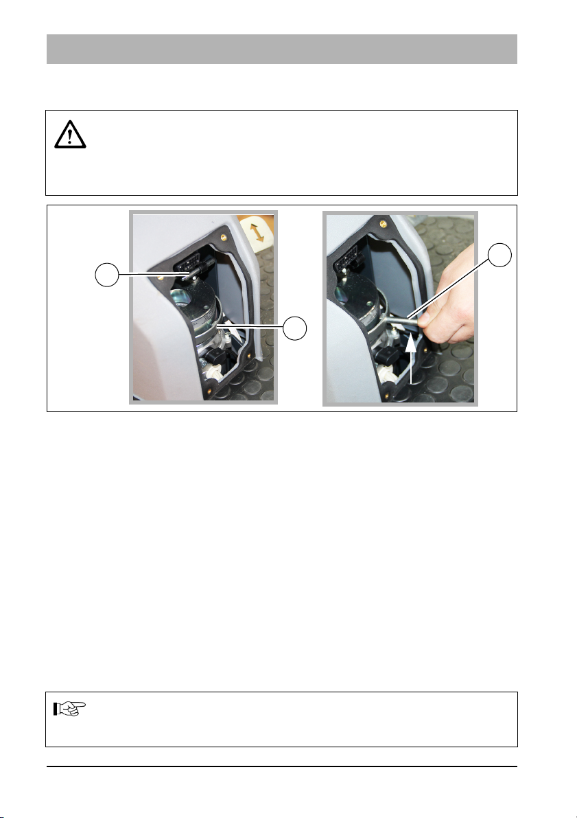
3.4.8 Pushing the machine
Danger
Risk of accident! When pushing the machine, it does not have any
braking effect.
After pushing the machine, only re-start it if the lever has been
positioned and the cover installed.
In order to push the machine, carry out the following steps:
1. Loosen the bolts of the cover to the drive using the supplied socket wrench
and remove the cover.
2. Remove the pin Fig. 19-A from the holder and screw it into the ring
Fig. 19-B.
3. In order to unlock the parking brake, slightly pull the pin upwards and
simultaneously push the machine.
4. Disassembly is in reverse order.
3.4.9 Turning off the machine
1. Slowly bring the accelerator pedal to the zero position. The machine slows
down to standstill. A better braking effect is achieved when the machine is
slowed down by applying the brake.
2. When the machine is at standstill, the parking brake is activated audibly.
3. Switch off the cleaning functions.
4. Switch off the machine using the key switch.
Note
Remove the key when leaving the machine to prevent unauthorised
use.
46 03-7177-00.fm

Putting into service
3.4.10 Checklist – after cleaning
Environmental danger
Observe the applicable laws and local regulations when disposing of
detergents.
Attention
Do not use a high-pressure cleaner or steam cleaner to clean the
machine.
No. Description
1 Drive to a suitable maintenance location.
2 Switch the machine off and pull out the key.
3 Empty and clean the waste water tank, see section 5.5.2.
4 Check the fresh water filter, see section 5.4.5.
5 Check the sealing strips and suction hose, see chapter Maintenance
and Servicing.
6 Check the functions and settings.
7 Charge the battery, see section 5.3.5.
8 Clean the machine. If the machine is not used over a longer period of
time, the solution tank must be fully emptied.
03-7177-00.fm 47

Putting into service
3.5 Loading and transporting
Attention
• When loading and subsequently transporting the machine to the
work site, the squeegee and brush head must be raised.
• Risk of skidding! Drive very carefully and, if possible, only on dry
ramps.
Loading
When loading the machine, observe its weight, see Section 4 Technical data.
Transporting
When transported on a vehicle or trailer, the machine must be secured
against tilting and rolling away. To do so, tie the machine down tightly using
clamping bands.
48 03-7177-00.fm

Putting into service
3.6 Service information
In case problems occur with the machine, a four-digit service code is output in
the display panel in addition to the service indicator (tool key).
The dots of the service code flash. Eliminate the cause or note down the
service code and inform your authorised Hako service partner.
If the cause has been eliminated, the fault must be acknowledged via the key
switch OFF/ON.
Service
Fault Cause Remedy
code
1.2.2.1 Brushes/Roller
Electrical defects Contact the customer
stop
1.2.5.2. Brushes stop Foreign particles
between brush and shaft
1.2.6.1. Brushes stop • Foreign particles block
the brush
• Brush not positioned
correctly in the holder
1.2.6.3. Brush lift
system, brush
and suction
• Foreign particles
between brush head
and machine
turbine have
been switched
off
• Foreign particles
between squeegee
and machine
• Squeegee jammed
1.4.6.1. Squeegee lift
system stops
Overload due to foreign
particles
service
Inspect the brushes for
foreign particles and
remove them if
necessary
• Inspect the brushes for
foreign particles and
remove them if
necessary
• Actuate the brush
decoupling system,
contact the service
partner, if necessary
• Inspect the brush
head for foreign
particles and remove
them if necessary
• Inspect the lift system
for foreign particles
and remove them if
necessary
• Make the squeegee
accessible
Inspect for foreign
particles and remove
them if necessary
03-7177-00.fm 49

Putting into service
Service
Fault Cause Remedy
code
1.4.6.3. Suction turbine
stops
3.2.6.6. Service code
indicator when
turning on the
machine
3.3.1.1. Service interval
expired
3.4.1.2. Driving not
possible
3.4.5.1. Cleaning function
switches off
3.6.6.4. Driving and
cleaning not
possible
5.8.7.0. Batteries are not
being charged
5.8.7.1. Batteries are not
being charged
Flashing
number
Driving not
possible
field
• Foreign particles in the
suction turbine
Contact the
customer service
• Faulty suction turbine
Discharged capacity of the
internal back-up battery of
Contact the
customer service
the machine control
See maintenance
plan
Error in the drive control Turn the machine
OFF/ON, contact
the customer
service if
necessary
• Drive wheel becomes
sluggish due to foreign
• Remove foreign
particles
particles
• Drive motor overheats
• Let the engine
cool down
Seat permanently loaded Relieve seat
• Cables on the battery
poles loose or detached
Contact the
customer service
• Incorrect type of battery
installed
• Mains plug not inserted
correctly
Insert the mains
plug correctly
• Incorrect type of battery
installed
• Seat not occupied
• Start sequence not
observed
• Occupy seat
• Observe start
sequence
50 03-7177-00.fm

4 Technical data
Dimensions
Technical data
Name
Length of machine with squeegee mm 1675 1675 1675 1675
Width of machine with squeegee mm 960 1120 960 1120
Width of machine without
squeegee
Height of machine mm 1440 1440 1440 1440
Unit TB 750 TB 900 WB 700 WB 850
mm 810 950 810 950
Working width
Brush unit mm 750 900 700 850
Squeegee mm 950 1100 950 1100
Weights
Weight (empty, without batteries) kg 340 355 324 326
Total weight (ready for use) kg 723
Permissible total weight kg 870
738
870
707 709
870 870
Driving performance
Driving speed transportation
(forwards/reverse)
Climbing capacity when cleaning % 2 2 2 2
Climbing capacity during transport
journey (ready for operation,
max. 1 minute)
Ramp angle/Slope angle % 18 18 18 18
Turning circle (with squeegee) mm 2470 2470 2470 2470
km/h 6.7/3.9 6.7/3.9 6.7/3.9 6.7/3.9
%10101010
Wheels
Wheel diameter mm 305 305 305 305
2
Specific wheel contact pressure
front/rear
04-7177-00.fm 51
N/mm
0,49/
0,48
0,49/
0,48
0,49/
0,48
0,49/
0,48

Technical data
Tank contents
Name
Solution tank Litre 120 120 120 120
Waste water tank Litre 120 120 120 120
Unit TB 750 TB 900 WB 700 WB 850
Brush head
Number of brushes Piece 2 2 2 2
Brush speed rpm 210 210 850 850
Min./Max. brush pressure kg 37/60 50/70 26/33 28/35
Vacuum system
Air quantity
Vacuum (maximum) mbar 170 170 170 170
3
m
110 118 110 118
/h
Electrical system
Nominal voltage V 24 24 24 24
Nominal output (max.) (P1) W 3260 3260 3100 3100
Power consumption drive motor (P1)
S2-120 min
Power consumption vacuum motor
(P1)
Power consumption brush motor (P1)
Power consumption water pump (P1)
W 816 816 816 816
W 528 528 528 528
W 2x960 2x960 2x876 2x876
W 100 100 100 100
Type of protection IPX3 IPX3 IPX3 IPX3
Protection class III III III III
On-board charger
Rated input/output voltage V 230/24 230/24 230/24 230/24
Nominal output W 1130 1130 1130 1130
Type of protection IP20 IP20 IP20 IP20
Protection class I I I I
52 04-7177-00.fm

Noise emission value
Technical data
The sound power level (L
conditions of use according to DIN EN 60335-2-72 is:
) measured under the customary
wAd
dB (A) 85
The sound pressure level (LpA) (at the ear of the driver) measured
under the customary conditions of use according to DIN EN
60335-2-72 is:
dB (A) 66
Measuring uncertainty (KpA)dB (A)2
Vibration
Under the customary conditions of use, the weighted effective
value of the acceleration to which the upper limbs (hand-arm) are
subjected to according to DIN EN ISO 5349 is:
Under the customary conditions of use, the weighted effective
value of the acceleration to which the body (feet or seat surface) is
subjected to DIN EN ISO 2631-1 is:
m/s
m/s
2
≤2.5
2
≤0.5
04-7177-00.fm 53

Maintenance and Servicing
5 Maintenance and Servicing
General
The operator is instructed fully on delivery of the machine.
Attention
Before undertaking servicing and maintenance work, read and
observe the safety instructions in chapter 1 of this operating manual!
Compliance with the maintenance work recommended by us gives you the
certainty of always having an operational machine available.
Daily and weekly maintenance and repair work can be undertaken by a driver
trained for this, all further Hako system maintenance work may be undertaken
only by trained and qualified personnel.
Please contact your nearest Hako service centre or authorised Hako dealer.
Any warranty claim is null and void if this is not complied with and damage
results.
Please always state the serial number in all enquiries and spare parts orders,
see section 1.7 – type plate.
Hako system maintenance
The Hako system maintenance specifies in single modules the special
technical work to be done and the periods of time for the maintenance
activities. Parts to be replaced for the individual maintenance tasks are
determined.
Hako system maintenance:
• Assures the reliable readiness for use of the Hako cleaning machines
(preventive maintenance).
• Minimises operating costs, repair costs, costs for maintenance.
• Assures long life and readiness for use of the machine.
Note
Maintenance parts in the machine are marked with a yellow dot and
yellow areas.
54 05-7177-00.fm

5.1 Maintenance certificate
Maintenance and Servicing
Handover
Equipment
Trial run
Handover to customer
Instruction
performed on:
at _______________ operating hours
Hako system maintenance I
750 operating hours
Workshop stamp
performed on:
at _______________ operating hours
Hako system maintenance II
1500 operating hours
Workshop stamp
performed on:
at _______________ operating hours
Hako system maintenance I
2250 operating hours
Workshop stamp
performed on:
at _______________ operating hours
Hako system maintenance I
250 operating hours
Workshop stamp
performed on:
at _______________ operating hours
Hako system maintenance S
1000 operating hours
Workshop stamp
performed on:
at _______________ operating hours
Hako system maintenance I
1750 operating hours
Workshop stamp
performed on:
at _______________ operating hours
Hako system maintenance II
2500 operating hours
Workshop stamp
performed on:
at _______________ operating hours
Hako system maintenance II
500 operating hours
Workshop stamp
performed on:
at _______________ operating hours
Hako system maintenance I
1250 operating hours
Workshop stamp
performed on:
at _______________ operating hours
Hako system maintenance S
2000 operating hours
Workshop stamp
performed on:
at _______________ operating hours
Hako system maintenance I
2750 operating hours
Workshop stamp
performed on:
at _______________ operating hours
Hako system maintenance S
3000 operating hours
Workshop stamp
performed on:
at _______________ operating hours
05-7177-00.fm 55
Hako system maintenance I
3250 operating hours
Workshop stamp
performed on:
at _______________ operating hours
Hako system maintenance II
3500 operating hours
Workshop stamp
performed on:
at _______________ operating hours

Maintenance and Servicing
5.2 Maintenance plan
Hako system maintenance customer:
Work to be performed by the customer by reference to the servicing and
maintenance instructions specified in the operating manual.
Activity / interval
Daily
• Empty the waste water tank, clean the waste water tank, drain hose,
coarse dirt sieve (option) and suction filter
• Check the cover seal of the waste water tank, clean if necessary
• Check the battery, charge if necessary
• Check the squeegee, clean if necessary
Weekly
• Clean the machine as required
• Clean the solution tank
• Check the sieve insert in the fresh water filter, clean or replace if necessary
• Check the scrubbing performance of the brushes/pads, clean if necessary
• Check the brushes and water retaining ring for proper fit and wear, replace
if necessary
• Check the suction performance of the squeegee, clean or replace the
sealing strips if necessary
• Check the fresh water supply to the brushes, clean if necessary
• Check the drain hose for tight fit and damage, clean if necessary
• Check the rubber of the lateral wiper, replace if necessary
• Trial run and function test
56 05-7177-00.fm

Maintenance and Servicing
Hako system maintenance I:
Performance by an expert of an authorised Hako workshop by reference to
the machine-specific system maintenance.
Activity / interval
Every 250 hours
• Check the battery and the charger
• Check the battery acid level and acid density, refill demineralised water if
necessary
• Check the air inlet grilles, air duct and filter mat of the on-board charger for
contamination, clean or replace if necessary
• Check the steering pinion and gear rim for damage, replace if necessary.
Lubricate as required.
• Check the brake for proper functioning
• Check the cover seal of the waste water tank, replace if necessary
• Check the seal at the drain hose, replace if necessary
• Check the leak tightness of the seal at the inspection cover, replace if
necessary
• Check the sealing strip/slot strip of the squeegee, turn or replace if
necessary
• Check the sieve insert and cover seal of the fresh water filter for damage,
replace if necessary
• Check the transparency of the level indicator hose, replace if necessary
• Check the rear wheel mounting screws, re-tighten if necessary (42 Nm)
• Check the condition of tyres
• Check the waste water and suction system, replace worn parts if
necessary
• Check the fresh water supply, replace worn parts if necessary
• Check the electrical system (lighting, fuses and relays), replace parts if
necessary
• Remove fluff and dirt from the air inlet grilles of the brush motors
• Check the squeegee setting, reset if necessary
• Check the front collision protection with deflecting roller for damage
05-7177-00.fm 57

Maintenance and Servicing
Hako system maintenance I (continued):
Activity / interval
Every 250 hours
• Check the hoses and connecting pieces to the differential pressure switch
in the tank cap for contamination, clean or replace if necessary
• Check the optical condition of the machine (corrosion and labels)
• Trial run and function test
Hako system maintenance II:
Performance by an expert of an authorised Hako workshop by reference to
the machine-specific system maintenance.
Activity / interval
Every 500 hours
• All maintenance work according to Hako system maintenance I
• Read the error memory and evaluate the error messages
• Check electrical performance (drive motor, brush motor and suction
turbine)
• Replace the backup battery of the electrical control and set a real-time
clock
• Trial run and function test
Hako system maintenance III/S (safety check)
Performance by an expert of an authorised Hako workshop by reference to
the machine-specific system maintenance. Performance of all legally
stipulated safety-relevant tests according to the BGV specifications.
Activity / interval
Every 1000 hours
• All maintenance work according to Hako system maintenance II
• Remove coal dust from the brush motors and check the carbon brushes
for ease of movement and wear, replace carbon brushes if necessary
• Trial run and function test
58 05-7177-00.fm

Maintenance and Servicing
5.3 Battery system
5.3.1 Type of battery
The machine variants are equipped with different maintenance-free battery
types. When using other batteries which have been approved by Hako,
corresponding settings must be carried out in the configuration menu. These
settings should only be carried out by a workshop authorised by Hako!
Type of battery
Trough battery 24 V/320 Ah PzS, wet
Trough battery 24 V/280 Ah PzS, gel
maintenance-free
Connection diagram
Driving direction:
Note
Pay attention to the installation position of the trough batteries!
05-7177-00.fm 59

Maintenance and Servicing
Type of battery
Block battery 6 V/180 Ah GiV, gel
maintenance-free
Block battery 6 V/240 Ah GiV, gel
maintenance-free
Connection diagram
Driving direction
:
60 05-7177-00.fm

Maintenance and Servicing
Fig. 20:
24 V
24 V
6V
6V
B
D
A
C
5.3.2 Battery plug coding
The plug connectors between the battery Fig. 20-A, the machine Fig. 20-B
and the charger Fig. 20-C are coded with coloured coded pins (yellow, grey or
green) Fig. 20-D depending on the type of battery and rated voltage.
When using other batteries which have been approved by Hako, the plugs
must be re-coded.
The following three prerequisites must be met for the whole system:
• Voltage coding (24 V) must be identical for all plugs and bushes.
• The colour of the coded pin in the connector housing of the machine is
always yellow.
• The colour of the coded pin in the charger plug (machines without built-in
charger) and in the bush housing of the battery must be identical:
• Grey for wet batteries
• Green for maintenance-free gel batteries
Warning
Risk of short circuit! The coding of the plugs should only be carried
out by a workshop authorised by Hako!
5.3.3 Battery management system (BMS)
The battery management system (BMS) ensures the battery system is
monitored and secure. The BMS is responsible for:
• determining the battery charging state during operation
• switching off the cleaning functions when the discharge limit has been
reached to protect the battery against total discharge
Attention
When using other batteries which have been approved by Hako, the
BMS must be reset in order to protect the battery against total
discharge. The settings of the BMS should only be carried out by a
workshop authorised by Hako!
05-7177-00.fm 61

Maintenance and Servicing
Fig. 21:
57
5.3.4 Checking the charging state
During operation, the charging state of the batteries is displayed in the display
panel Fig. 21-57. Different numbers of fields are displayed depending on the
charging state.
Battery charging
state indicator
Charging state Notes
Four fields visible:
Battery is fully
charged
Three fields visible:
Battery is charged
Charging / recharging of the
batteries is not recommended.
to approx. 2/3
Two fields visible:
Battery can be charged.
Battery is charged
to approx. 1/3
One field visible: Cleaning functions are switched
off after 3 minutes.
One field is flashing
and a signal is
output
Machine can only be further
operated at reduced speed.
Charge the batteries
immediately!
62 05-7177-00.fm

5.3.5 Charging the batteries
Warning
• Risk of explosion! Explosive gases can develop when charging
the batteries.
Avoid smoking, fire or naked light in the vicinity of batteries.
Ensure sufficient ventilation when charging the batteries. Do not
inhale battery gases!
• Danger of explosion due to short circuits and spark formation!
Never place tools or other electrically conductive objects on the
battery!
Attention
• Before initially starting up the machine, charge the used batteries
fully and appropriately with commissioning charge. Please
observe the operating manual of the charging device and the
operating manual of the battery manufacturer. Hako assumes no
liability for battery damage resulting from insufficient
commissioning charge.
• Never leave batteries discharged, always recharge them
immediately.
• If possible, charge the batteries fully to ensure optimum service
life of the batteries. The charger is designed as a continuous
charger and retains the charging state of the batteries (trickle
charge) after completing the charging process.
• The battery should always be charged without being interrupted.
• During the charging process it is not possible to turn on the
machine.
• The seat console must remain open when charging the batteries.
Maintenance and Servicing
05-7177-00.fm 63

Maintenance and Servicing
Fig. 22:
1
2
3
4
57
Charging the batteries with the on-board charger
The batteries are charged via the integrated on-board charger. The batteries
can be charged if two fields of the charging state indicator Fig. 21-57 have
gone out, at the latest, however, after the cleaning functions have been
switched off (one field flashes).
1. Place the machine on a level surface and turn it off.
2. Remove the mains plug Fig. 3-2 from the tray and plug it into a 230 V
socket.
3. The charging process now starts automatically.
Note
If the battery is not used for longer than three months, interim charge
the batteries.
Only park unused machines when switched off and in a dry location.
Checking the charging process
During the charging process, the charging progress is displayed in the display
panel Fig. 22-57:
• Field 1 permanently ON, running light in fields 2, 3 and 4:
Main charge <50 % charged battery capacity
• Fields 1 and 2 permanently ON, running lights in fields 3 and 4:
Main charge >50 % charged battery capacity
• Fields 1, 2 and 3 permanently ON, field 4 flashes: Recharge
• All fields permanently ON: End of charging process / trickle charge
Note
An error is present when the battery symbol flashes in connection
with a field, see operating manual of the charger, contact the Hako
customer service if necessary.
64 05-7177-00.fm

Maintenance and Servicing
Fig. 23:
A
B
C
E
D
Charging the battery with a stationary charger
Attention
Observe the information in the instruction manual of the charger
manufacturer!
Charge the batteries with a stationary charger as, for example, shown in
Fig. 23-A. The batteries can be charged when two fields in the charging
status indicator Fig. 22-57 have gone out.
1. Place the machine on a level surface and turn it off.
2. Disconnect the battery plug Fig. 23-B from the machine plug Fig. 23-C.
3. Connect the battery plug to the plug of the charger Fig. 23-D.
4. Switch on the charger.
5. The progress of the charging process is displayed in the display Fig. 23-E
of the charger. In the meantime, the charging control indicator Fig. 22-57 in
the display panel is not active!
6. Once the battery is fully charged, terminate the charging process:
• Switch off the charger.
• Disconnect the battery plug from the plug of the charger and reconnect it
to the plug of the machine.
05-7177-00.fm 65

Maintenance and Servicing
Fig. 24:
A B
5.3.6 Checking the acid level
Warning
Risk of explosion and fire! When handling batteries, it is prohibited to
smoke and use an open fire.
Attention
• Observe the information in the operating manual of the battery
manufacturer!
• Refilling must only take place once the battery charging process
has been terminated.
Note
Batteries approved by Hako are equipped with an aquamatic
system.
The customer has to check the acid level of the battery weekly, demineralised
water (according to DIN 43530-4) must be refilled if necessary.
If the trough battery is equipped with an aquamatic system Fig. 24-A, each
individual cell features a sealing plug with float indicator. The white dot must
be located at the top and must be clearly visible. If this is not the case, refill
demineralised water.
To do so, connect the end piece of the aquamatic system Fig. 24-B to a
container with demineralised water. Observe sufficient gradient, ensuring the
water can flow into the cells. If the required level has been reached, the plugs
automatically seal the cells and indicate “full”.
66 05-7177-00.fm

Maintenance and Servicing
5.3.7 Replacing the batteries
Attention
• Only use batteries approved by Hako at the intended position!
• Use suitable lifting equipment when inserting/replacing batteries.
• When changing the type of battery, the battery holder in the
battery compartment might have to be adjusted to prevent
slipping.
• The batteries should only be replaced by qualified service
personnel!
For reasons of safety, we recommend that an authorised
Hako workshop carries out these tasks.
• When using other batteries which have been approved by Hako,
the BMS must be reset to protect the battery against total
discharge. The settings of the BMS should only be carried out by
a workshop authorised by Hako!
5.3.8 Maintaining drive batteries
For maintaining and servicing drive batteries, see Hako supplementary sheet
88-60-2556 – information for drive batteries.
5.3.9 Disposing of batteries
Used batteries with the recycling symbol contain reusable commodities. They
must not be disposed of in domestic waste, see Section 1 Environmental pro-
tection instructions and disposal.
05-7177-00.fm 67

Maintenance and Servicing
Fig. 25:
196
30
A
A
B
Fig. 26:
5.4 Solution tank
5.4.1 Filling the solution tank
Fill the solution tank Fig. 28-6 before commencing work or as required.
1. Place the machine on a level surface.
2. Open the tank cap.
3. Remove the insert of the filling opening Fig. 26-A.
4. Fill the solution tank up to the maximum (1/1) mark Fig. 25-A (maximum
water temperature 50 °C).
5. Add detergent according to the manufacturer's regulations via the sieve
insert Fig. 26-B.
68 05-7177-00.fm

Maintenance and Servicing
Fig. 27:
B
max. 50 °C
min. 2.5 bar
max. 6 bar
C
A
5.4.2 Automatic filling unit (option)
Optionally, the solution tank can be filled via the automatic filling unit.
Attention
According to DIN EN 1717, the automatic filling unit must not be
operated without a system separator (operating manual).
1. Fit the water connection Fig. 27-A. Do not yet open the water supply!
2. Push the operating button Fig. 27-B. The indicator knob Fig. 27-C
protrudes.
3. Open the water supply – water starts to flow.
4. The filling unit switches off automatically when the tank is full. The indicator
knob Fig. 27-C no longer protrudes.
5. Close the water supply and remove the water connection.
Use a water line fitted with a stop valve!
Note
The machine can also be filled manually through the opening in the
operating button Fig. 27-B. Check the level in the level indicator
Fig. 25-30.
05-7177-00.fm 69

Maintenance and Servicing
Fig. 28:
29
A
B
24
21
5.4.3 Emptying the solution tank
There are three options to empty the solution tank:
Emptying the solution tank via the fresh water filter
Position the machine ensuring the fresh water filter Fig. 28-24 is above a
drain in the ground.
1. Close the ball cock Fig. 28-B located in front of the fresh water filter.
2. Unscrew the filter cover by hand.
3. Open the ball cock fully. The solution tank is emptied via the fresh water
filter.
70 05-7177-00.fm

Maintenance and Servicing
Fig. 29:
37 28
A
Emptying the solution tank via the maintenance opening
Position the machine ensuring that the maintenance opening Fig. 28-29 is
above a drain in the ground.
1. Turn and remove the cover of the maintenance opening.
2. The solution tank is emptied via the maintenance opening.
3. After emptying the tank, place the cover on the maintenance opening and
screw tight.
Note
To facilitate loosening and closing the cover, use the supplied
handle Fig. 28-A.
Emptying the solution tank via the vacuum system
This method is recommended if no drain is available and the waste water tank
is empty.
1. Turn off the machine.
2. Close the ball cock Fig. 28-B.
3. Turn and remove the filter cover of the fresh water filter Fig. 28-24.
4. Remove the suction hose Fig. 29-28 from the squeegee A and plug it onto
the filter housing Fig. 29-A.
5. Open the ball cock fully.
6. Switch on the suction turbine via button Fig. 29-37. The fresh water is
conveyed into the waste water tank.
05-7177-00.fm 71

Maintenance and Servicing
Fig. 30:
A
B
5.4.4 Cleaning the solution tank
Attention
Overflowing water! Only open the cleaning opening Fig. 28-21 when
the solution tank is empty.
Note
To facilitate loosening and closing the cover of the maintenance
unit, use the supplied handle Fig. 28-A.
1. Empty the solution tank, see section 5.4.3.
2. Turn and remove the cover of the maintenance opening Fig. 28-29.
3. Unscrew the cover of the cleaning opening Fig. 28-21.
4. Feed the water hose through the cleaning opening and clean the solution
tank thoroughly.
5. After cleaning the tank, close the cleaning opening with the cover.
6. Place the cover onto the maintenance opening and screw tight.
7. After filling the solution tank, check the cover of the maintenance unit for
leak tightness. If necessary, screw the cover tighter.
5.4.5 Cleaning the fresh water filter
Check the filter sieve Fig. 30-B of the fresh water filter Fig. 28-24 weekly and
clean or replace it as required.
1. Close the ball cock Fig. 28-B.
2. Turn and remove the filter cover Fig. 30-A.
3. Remove the filter sieve Fig. 30-B from the filter housing and clean it under
running water. Replace the filter sieve as required.
4. Reinsert the filter sieve and filter cover and open the ball cock.
72 05-7177-00.fm

Maintenance and Servicing
18
27
17
52
Fig. 31:
Fig. 32:
B
C
D
A
5.5 Waste water tank
5.5.1 Emptying the waste water tank
Clean the waste water tank Fig. 31-17 daily or as required. When the waste
water tank full symbol Fig. 31-52 is displayed in the display panel and an
acoustic warning signal is output, the cleaning functions are switched off and
the waste water tank should be cleaned immediately.
Environmental danger
Observe applicable laws and local regulations when disposing of
detergents!
1. Drive to a suitable disposal centre.
2. Position the machine, ensuring the drain hose Fig. 31-27 reaches the drain
in the ground.
05-7177-00.fm 73

Maintenance and Servicing
B
A
C
Fig. 33:
16
3. Turn off the machine.
4. Remove the drain hose from the holder. Push the suction hose Fig. 32-A
slightly to the side so that the waste water tank can be emptied fully via the
drain hose.
5. Bend the squeeze nozzle in the front section Fig. 32-B.
6. Remove the cap Fig. 32-C.
7. Return the drain hose to its original position Fig. 32-D and empty the waste
water tank fully.
8. After emptying the tank, seal the drain hose with the cap.
5.5.2 Cleaning the waste water tank
Clean the waste water tank daily or as required.
1. Empty the waste water tank, see section 5.5.1.
The drain hose with open cap remains positioned at the drain in the ground.
2. Open the tank cap Fig. 33-A of the waste water tank.
• Put one hand in the recessed grip Fig. 33-B of the tank cap.
• Open the tank cap until the support Fig. 33-C engages.
3. Clean the waste water tank thoroughly with the water hose.
4. Also flush the drain hose.
5. Close the tank cap:
• Put one hand into the recessed grip Fig. 33-A and open the tank cap a
little further.
• Unlock the support
5.5.3 Coarse dirt sieve (option)
Fig. 33-B
with your left hand and close the tank cap.
A coarse dirt sieve Fig. 31-18 is optionally located in the waste water tank.
Clean the sieve daily or as required.
74 05-7177-00.fm
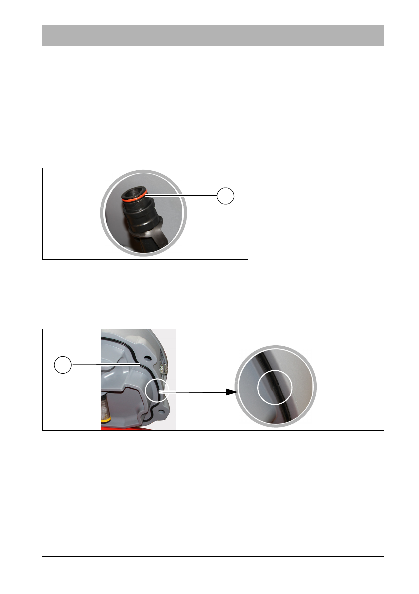
Maintenance and Servicing
Fig. 34:
A
A
Fig. 35:
5.5.4 Cleaning the suction filter
Check the function of the suction filter Fig. 33-16 daily and clean it as
required.
1. Remove the suction filter from the neck.
2. Clean the suction filter under running water.
3. Mount the suction filter on the neck again.
5.5.5 Checking the seal at the drain hose
Check the function of the seal at the drain hose Fig. 34-A daily, replace it after
125 operating hours at the latest.
After use, check the drain hose for soiling and clean if necessary.
5.5.6 Checking the seal in the tank cap
Check the function of the seal in the tank cap Fig. 35-A daily and replace it if
damaged.
When replacing the seal:
• Ensure that the installation position is correct.
• Ensure that the seal is pressed fully into the groove.
• Ensure that the seal is seated correctly.
05-7177-00.fm 75

Maintenance and Servicing
Fig. 36:
7
7
A
8
B
Fig. 37:
A
5.6 Rotating brush unit
5.6.1 Replacing the brushes/pads
Use the indicator Fig. 37-A on the rotating brush unit to:
• determine the wear of the brushes/pads (the rotating brush unit must be
lowered)
• determine whether the brushes/pads have been assembled.
Change the brushes/pads at the latest when the red pointer is in the red zone.
1. Decouple the brush/pad, see section 5.6.3
2. Insert the new brush/pad, see section 5.6.4
Attention
If no brushes/pads have been assembled, the red pointer is in the
red zone of the indicator.
76 05-7177-00.fm

Maintenance and Servicing
Fig. 38:
7
Fig. 39:
5.6.2 Cleaning the brushes
Clean the brushes Fig. 36-B in the rotating brush unit Fig. 36-8 daily or as
required.
1. Decouple the brush, see section 5.6.3.
2. Thoroughly clean the brush under running water.
3. Couple the brush, see section 5.6.4.
Note
Make sure that the cleaned brushes are installed on the same side
in the rotating brush unit where they were removed.
5.6.3 Decoupling the brushes/pads
1. Turn off the machine.
2. Swing down the wiper, see section 5.7.1.
3. To decouple the brushes/pads, press down the brush decoupler Fig. 38-7
with your foot.
5.6.4 Coupling the brushes/pads
:
1. Make sure that the rotating brush unit has been raised and the machine has
been switched off.
2. Place the brush/pad underneath the brush head holder.
3. Raise the brush/pad and press it firmly into the holder Fig. 39.
4. Turn the brush/pad fully and use your hand to press it again until the
brush/pad has engaged completely.
05-7177-00.fm 77

Maintenance and Servicing
Fig. 40:
9 A
B
C
5.7 Wiper
5.7.1 Swinging down the wiper
In order to change the brushes, raise the wiper Fig. 40-9 at the handle and
swing it to the side.
When raised, the wiper can be fixed into position with the locking lever
Fig. 39-A.
5.7.2 Replacing the rubber of the wiper
Check the rubber of the wiper weekly for wear, turn or replace the rubber if
necessary.
1. Loosen the wing nut Fig. 40-B.
2. Remove the clamping band Fig. 40-C.
3. Turn the rubber of the wiper (can be used 4 times) or replace it.
4. Assembly is in reverse order.
78 05-7177-00.fm
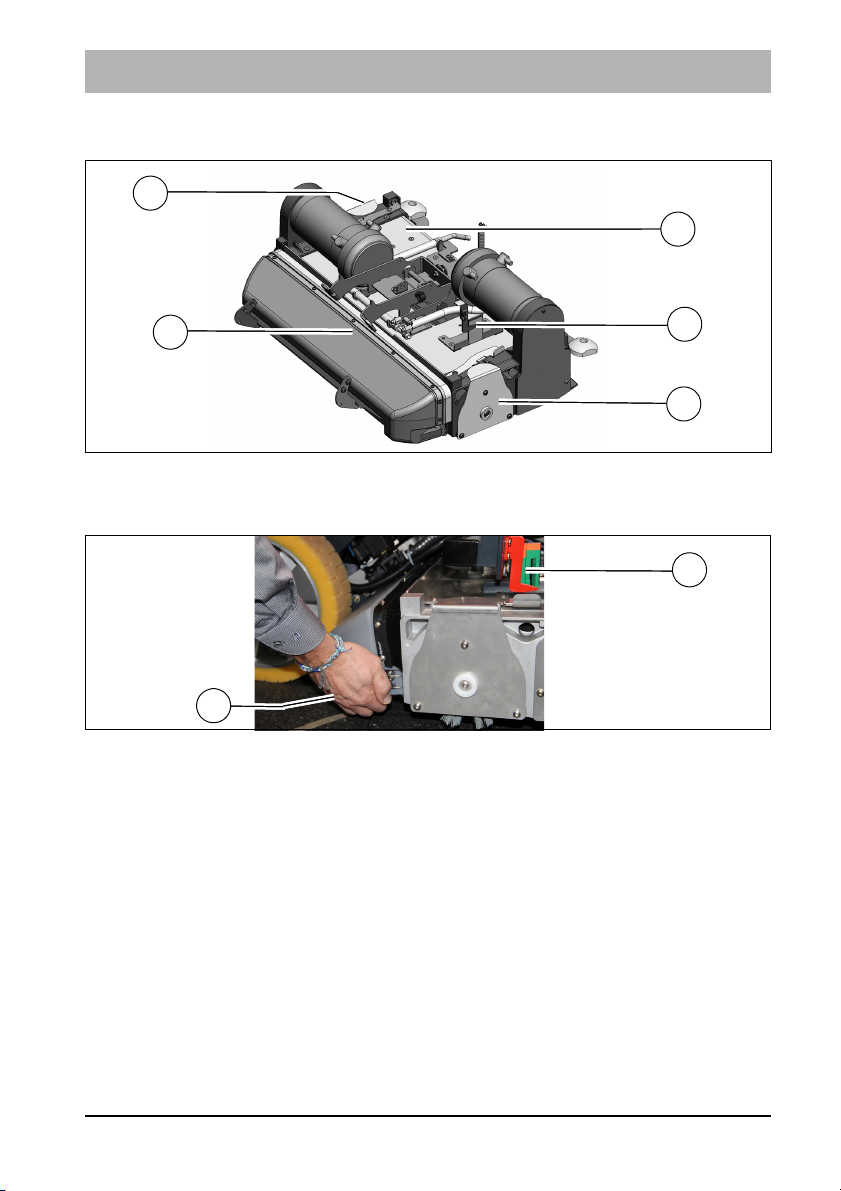
Maintenance and Servicing
Fig. 41:
B
A
C
C
23
Fig. 42:
A
B
5.8 Roller brush unit
5.8.1 Emptying the dirt hopper
Empty the dirt hopper Fig. 41-A daily or as required.
1. Turn off the machine.
2. Swing down the wiper on the right-hand side of the machine.
3. Put one hand in the recessed grip below the dirt hopper and remove the dirt
hopper.
4. Empty the dirt hopper.
5. Assembly is in reverse order.
5.8.2 Replacing the brushes
Change the brushes at the latest when the pointer in the indicator Fig. 42-B is
in the red zone, also see section 5.6.1
1. Disassemble the brushes, see section 5.8.4
2. Install the brushes, see section 5.8.5
05-7177-00.fm 79

Maintenance and Servicing
Fig. 43:
X
A
B
C
D
5.8.3 Cleaning the brushes
Clean the brushes Fig. 41-C in the roller brush unit Fig. 41-23 daily or as
required.
1. Disassemble the brush, see section 5.8.4.
2. Thoroughly clean the brush under running water.
3. Install the brush, see section 5.8.5.
5.8.4 Disassembling the brushes
1. Turn off the machine.
2. Swing down the wiper, see section 5.7.1.
3. Unlock the brush holder Fig. 43-A:
Press the locking lever Fig. 43-B into position C and remove the brush
holder.
4. Pull out the brush.
5.8.5 Installing the brushes
1. Push the brush into the housing (teeth X must point to the outside) and let
the catch on the opposite side engage audibly.
2. Press the locking lever Fig. 43-B into position C and install the brush
holder.
3. Lock the brush holder:
Push the locking lever into position D.
4. Swing up the wiper, see section 5.7.1.
80 05-7177-00.fm

Maintenance and Servicing
Fig. 44:
26
A
B
A
28
5.8.6 Squeegee
Optimum vacuuming is achieved through:
• clean and undamaged or not worn sealing strips
• correctly set inclination angle and correct height adjustment of the sealing
strips.
.
5.8.7 Cleaning the squeegee
Check the squeegee Fig. 44-26 daily for soiling and foreign particles and
clean it as required.
1. Pull out the suction hose Fig. 44-28, loosen the two star-shaped handles
Fig. 44-A and remove the squeegee.
2. Thoroughly clean the squeegee and remove foreign particles.
3. Assembly is in reverse order.
05-7177-00.fm 81

Maintenance and Servicing
A
C
E
Fig. 45:
C
B
D
F
5.8.8 Replacing the sealing strips
Check the sealing strips Fig. 45-A at the squeegee weekly for wear and
intactness. If the used sealing edge of the sealing strip is worn or damaged,
turn or replace the sealing strip. Each sealing strip can be used four times
before it needs replacing.
Size 950 squeegee:
1. Pull out the suction hose Fig. 44-26.
2. Loosen the star-shaped handles Fig. 44-B and remove the squeegee.
3. Press together the protective caps Fig. 45-C and pull them out.
4. Loosen the clamping band Fig. 45-D and remove it from the catch
Fig. 44-B.
5. Pull out the aluminium body Fig. 45-E from the top.
6. Remove the sealing strips Fig. 45-A from the plastic body Fig. 45-F.
7. Before turning or replacing the sealing strips, thoroughly clean the plastic
body!
8. Assembly is in reverse order.
Size 1100 squeegee (not shown):
1. Pull out the suction hose.
2. Loosen the star-shaped handles and remove the squeegee.
3. Press together the protective caps and remove them.
4. Open and remove the inner and outer clamping bands.
5. Turn or replace the sealing strips.
6. Assembly is in reverse order.
82 05-7177-00.fm

Maintenance and Servicing
Fig. 46:
B
A
Fig. 47:
5.8.9 Adjusting the sealing strips
Inclination adjustment
The correct inclination adjustment is decisive for:
• ensuring that the sealing strips of the squeegee rest evenly with the
complete contact surface on the ground
• ensuring that the squeegee runs smoothly and evenly during the suction
process.
1. Place the machine on a level surface and lower the squeegee.
2. Loosen the lock nuts Fig. 46-A and turn the threaded bar Fig. 46-B to
adjust the squeegee ensuring both ends of the sealing strips barely have
contact with the ground.
• Turn the threaded bar counter-clockwise: The distance of the sealing
strip to the ground increases at the ends Fig. 46.
• Turn the threaded bar clockwise: The distance of the sealing strip to the
ground decreases at the ends Fig. 47.
3. Turn on the machine and check the suction pattern. When driving, the
sealing strips must be turn over evenly everywhere (centre and outside).
4. Tighten the lock nuts of the threaded bar to 54 Nm.
05-7177-00.fm 83

Maintenance and Servicing
Fig. 48:
A
X
2 mm
3 mm
4 mm
Height adjustment
The height adjustment (X) of the supporting rollers Fig. 48-A has been set to
3 mm in the factory. If striping still occurs despite optimum inclination
adjustment, set the distance of the supporting rollers to the lower edge of the
sealing strip by adjusting the number of washers under the supporting roller
holder.
Number of washers /
distance to the
ground (X)
1/2 mm Very smooth floor surfaces, e.g. coated screed,
2/3 mm Standard setting
3/4 mm Very uneven floor surfaces, e.g. poorly laid tiles
Use
PVC, linoleum
(water does not drain off)
84 05-7177-00.fm

Maintenance and Servicing
5.9 Options
The following options are available for Scrubmaster B120 R.
Designation Order no.
On-board chemical dosing system, see section 3.4.2 7678.50
Comfort driver's seat 7093.20
Working spotlight 7091.20
Warning device 7091.30
Coarse dirt sieve, see section 5.5.3 7060.50
Manual suction tool, including holder 7036.80
Manual spray suction tool 7036.90
Holder for cleaning utensils 7031.20
Tray, see section 2.3.6 7009.50
Automatic filling unit 7743.10
Fleet-Recorder Standard 5301.20
Note
Please refer to the price list for information on pads, rotating and
roller brushes as well as more options.
05-7177-00.fm 85

Maintenance and Servicing
86 05-7177-00.fm

EC Declaration of Conformity
(corresponding to the EC Directive 2006/42/EC)
EC Declaration of Conformity
Hako GmbH
Hamburger Str. 209-239
23843 Bad Oldesloe, Germany
declare in sole responsibility that the following product
Scrubmaster B120 R, type: 7177
on which this declaration is based corresponds with the relevant basic safety
and health requirements of the EC Directive 2006/42/EC as well as the
requirements according to 2014/30/EC.
The following standard(s) and technical specifications was/were referred to for
the correct implementation of the safety and health requirements named in the
EC Directive:
EN 60335-2-72
EN 55012
EN 61000-6-2
Name of the authorised person who compiles the technical documents for
Hako:
Ludger Lüttel
Bad Oldesloe, 26.06.2017
Ricardo Ruiz Porath
Productlinemanager - Cleaning Technology
87

 Loading...