


Foil 1
Hakomatic B 1100
(7580.02)(7580.35)
Hakomatic B 1050
(7580.12/22)(7580.16/26)(7580.15)
Service-Handbuch
Service Booklet
Hako GmbH . Technisches Produktmanagement . D-23840 Bad Oldesloe . Stand 04/2012
Vertraulich – nur für den internen Gebrauch . For internal use only!
Schulung/Training
Fehlersuche/Trouble Shooting
Einstelldaten/Adjustments

Foil 2
Contents
1 Remarks 5
2 General 7
2.1 Settings 8
2.2 Brief Description 11
2.2.1 Switch Off Suction/Recovery Tank Filled Up 14
2.2.2 Initial Position Of Machine/Release, Lock Functions 15
3 Check Settings For Machine Type, TSG And Options,
Display And Delete Last Error 18
3.1 Check And Set Machine Type 23
3.2 Check And Set Options 24
3.3 Check And Set TSG 25
3.4 TSG Error 3211 28
3.5 View And Delete Last Appeared Error In The Display 29
4 Programming Different Cleaning Function Procedures Depending On
Accelerator Position (Check And Set) 30
4.1 Programme Functions 32

Foil 3
Contents
5 Specific Customer Settings (Display Of Last Error And Selection Of
Water Stage, Cleaning Agent, SWA, Side Brush, Filter) PPV 37
5.1 PPV1 40
5.2 PPV2 41
5.3 PPV3 42
5.4 PPV4 43
5.5 PPV5 (B 1100 only) 44
5.6 PPV6 (B 1100 only) 45
5.7 PPV7 (B 1100 only) 46
5.8 PPV8 (B 1100 only) 47
6 Setting Of Modules 48
6.1 Module 1 49
6.2 Module 3 50
7 Settings Of CAN Operator Panels (B 1100 only) 51
8 Water Pump 52
8.1. Water Amounts 52
8.2 Standstill Detection for Water Pump 54

Foil 4
Contents
9 Drive Controllers 55
9.1 SEVCON Controller (Diagnostic LED) 55
9.1.1 Signal Measurement On Controller (SEVCON) 58
9.2 ATECH / ZAPI Controller 63
9.2.1 Automatic Monitoring Of Components 65
9.2.2 Error Messages Displayed Via LED 66
9.2.3 Explanations For Displayed Error Messages 67
9.3 Drive Motor Hakomatic B1050 (Amer) 84
9.3.1 Tyre replacement 84
9.3.2 Check / replacement of carbon brushes 88
9.3.3 Diagnostic LED for drive control unit (Italsea) 89
10 Error Table With Information On Service Display 91
11 Notes 113

Foil 5
This document is structured so as to allow and seek continuous extension. You thus
receive the documents with the annotation that more or revised pages are to follow in
future.
This decision has been taken to allow adding modifications made to the machine
equally to the documents as revisions.
Beyond that this document may be improved upon your advice and proposals. I would
thus be grateful to receiving your feedback.
1. Remarks

Foil 6
Caution :
• Before working at the machine, disconnect voltage supply (pull battery plug)
except for the purpose of voltage and current measurement.
• When replacing stripe fuses, only loosen screws. Do not remove them completely
- short-circuit hazard.
Make sure to fully and evenly insert new blade fuses under the screws.
• After each repair proceed to starting and service current measurement to allow
detection of eventual defects.
• When working at the machine, comply with the general safety and accident
prevention regulations as provided by law.
1. Remarks

Foil 7
The Hakomatic B 1100 and the Hakomatic B1050 are equipped with a service indication
in the hourmeter display. Upon switching the key switch ON, a 4-digit code describing
the software version (e.g. 3.018), is displayed for about 3 seconds, followed by another
4-digit code signalling the last error which again is followed by the hourmeter indication.
Upon launch of the Hakomatic B1050, software version has updated to 4.020.
With the software revision 4.026 the Hakomatic B1100 TB 1230 was introduced.
As soon as a malfunction occurs, the red LED signalling a defect lights up and a warning
buzzer sounds. The current error code appears (as 4-digit alpha-numeric code in the
service display) with blinking dots between the digits. When all these criteria are met,
the error is a current one!
There is NO error code, containing a “0”.
Find the error codes listed in a table in chapter 11.
This document uses the following abbreviations:
TSG - low discharge signal sender
SWA - dirty water recycling
2. General

Foil 8
Settings on the control electronics/panel which have to be set and checked on
each machine:
In contrast to the Hakomatic B1100, scope of performance of the Hakomatic B1050 is
reduced and does not feature all the options available in the Hakomatic B1100. The
Hakomatic B1050PB (Plate Brush aggregate) has the side scrub unit optionally
available only; the Hakomatic B1050CB (Cylindrical Brush aggregate) has the side
broom unit optionally available, while the pre-sweeper, dirty water recycling and
cleaning agent dosage (99756402) options are available and settable for the
Hakomatic B1100 only. The B1050 PB 1230 doesn´t have any options adjustable via
the control moduls of the machine control system.
The Hakomatic B1100 PB1230 is equipped with the pre-sweep unit generally.
Machine type
TSG (low discharge signal sender - also called LDS)
Options
Delete display of last error after repair
Programme variants depending on the accelerator position
2.1 Settings

Foil 9
Settings which may be set via operator panel according to customer
requirements:
Display of last (remedied) error upon switching machine ON
Selection of water stage upon start of cleaning
Cleaning agent ON in addition to switching water ON (B1100 &
B1100 PB 1230 only)
Switching over to SWA upon switching water ON (B1100 only)
Side brush additionally ON in addition to switching ON scrubbing (B1100 and
B1050 PB only)
Side broom additionally ON in addition to switching ON scrubbing (B1050CB)
Filter shaking (B1100 only & B1100 PB 1230 )
Filter suction ON in addition to sweeping ON (B1100 only & B1100 PB 1230 )
Automatic filter shaking after sweeping (B1100 only & B1100 PB 1230 )
2.1 Settings

Foil 10
Settings at Module 1:
Dip-switch for electronic circuit-breakers
Settings at Module 3:
Dip-switch for electronic circuit-breakers and module coding
Settings at the additional operator panels (B1100 only):
Dip-switch for operator panel coding
2.1 Settings

Foil 11
Machine control is effectuated via the following electronics:
Control electronics
Module 1
Module 3 (for pre-sweeper, side broom and side brush, 3rd brush options)
Operator panel
Cleaning agent dosage /SWA operator panel (B1100 only)
Pre sweeper operator panel (B1100 only)
Cleaning agent module (optional, B1100 only)
Auxiliary voltage module (36V/24V transformer)
Voltage to the electronics is supplied by the auxiliary voltage module which transforms
36 Volts to 24 Volts. As the electronics are the same as integrated in the B910 and B
750R machines, the 24V electronics have to be transformed for use in the B 1100 and
B1050 machines. Components such as the motors and pumps, however, are still 36V
components.
The 24V voltage supply must not, even under load, fall below 23V since otherwise, supply
of the modules 1 and 3 would be insufficient and cause a CAN error (4000 error code).
2.2 Brief Description

Foil 12
The control electronics covers all control and monitoring functions in the machine
except for drive control.
Operation of drive controller is independent from the other electronics and only the
release signal and the signal for speed reduction are transmitted via control
electronics to drive controller. Beyond that, a signal is transmitted from drive controller
to control electronics for forward and reverse ride.
Upon occurrence of a defect on the drive controller, an error code is not output since
this controller has its own diagnostic indicator (see chapter 10).
The buttons for scrubbing, suction, scrubbing and suction and the green Hako button
for combined cleaning may be switched arbitrarily such that the selected function is
activated. Pre-sweeper/side broom and /or side brush function can be activated or de-
activated disregarding of the selected cleaning mode, if present in the machine.
The remaining functional buttons (water, brush ground pressure) allow activating or
de-activating the related functions in addition to the cleaning procedure without effect
on the running function.
2.2 Brief Description

Foil 13
The machine is equipped with a seat switch. Activation of this switch is required before
switching key switch on since otherwise sweeping and scrubbing functions (even in
combination) are locked. If the seat switch is not activated, suction can only be
activated for the „Hand suction hose“ option.
A reset of the machine after it was deactivated by the seat contact switch, is realized
by switching off and on again with the key switch.
Constant activation of the seat switch is also required. Leaving the seat while key
switch is ON causes locking of the functions.
The seat contact switch is 3 seconds delayed.
At the Hakomatic B1050 machines the sequence of switching on the machine (key
switch, seat contact switch), has no influence to the ability of function of the machine.
It is equally required to release parking brake to enable cleaning functions and drive
control is released.
To switch on the “TOOL”-function of the B1050 machines, it is necessary to activate
the brake of the machine.
2.2 Brief Description

Foil 14
The suction function is either stopped by the operator via button actuation or
automatically upon the „recovery tank filled up“ signal.
Switching off by operator:
Squeegee is lifted up
Suction motors switch off delayed (15 seconds)
Switching off after tank filled up:
The switch signalling „recovery tank filled up“ opens as soon as the tank is filled
If switch is open for 3 seconds or longer (spill protection) squeegee will be lifted
and the suction motors switch off with a delay of 15 seconds.
2.2.1 Switch Off Suction /
Recovery Tank Filled Up

Foil 15
When turned ON and the seat switch closed, all units of the machine are set to „initial
position“.
This means that the control electronic triggers all units (lifting elements and motors).
Lifting elements will be lifting up as long as they are not switched off by the microswitch controlling the upper limit position and integrated in the lifting element.
This means that the outputs for the lifting elements are powered for approx. 6 sec
every time the machine is switched on. During this time a voltage can be measured at
the outputs for the lifting elements.
Motors are off and the cleaning unit LED indication in the operator panel extinguishes.
The drive controller is transmitted the release signal.
Should the seat switch not be activated, the motors will also be turned off - for safety
reasons - but the lifting elements will not be lifting and the travel drive controller will
not be released either.
The only exception: water suction by hand hose (B1100).
2.2.2 Initial Position/Release,
Lock Functions

Foil 16
Before operation of the pre-sweeper (B1100 & B1100 PB 1230 only), the hood is to be
closed and the dirt hopper correctly inserted. The hood and the dirt hopper are
monitored each by a switch (NC switch) being serially connected. As soon as the
switch opens, the LED in the standard operator panel lights to signal „open hood“ and
the pre-sweeper function is disabled. Since both switches are serially connected, this
LED equally lights if the switch signalling „no dirt hopper inserted“ opens. In case of
faulty function, check the switch and all cable connections and connectors.
Another safety request is effected by the thermal switch of the broom motor. If this
switch opens, the pre-sweeper function will be disabled and an error code appears.
After engaging the parking brake, all cleaning functions will be disabled and the red
LED „brake engaged“ lights. This switch is an NC switch as well and it is thus
required, in case of faulty function, to check the switch, all cable connections and
connectors.
2.2.2 Initial Position/Release,
Lock Functions

Foil 17
Activation of the „Brushes“ function causes lowering of the brush head to the so-called
central position. The lifting element does not attain the lower limit position before
cleaning with increased ground pressure. The brush head lifting element thus has 3
micro-switches integrated, one each for the upper, the central and the lower limit
position.
Extracting the side brush unit is possible only after the brush head had lowered or in
other words: if the central position micro-switch does not switch, the „brush lowering
completed“ signal is missing and the side brush does not swing out. This signal
depends on the central position micro-switch only such that swinging out of side brush
is possible as well for cleaning with increased brush ground pressure. Since on its way
down to the lower limit position the central position micro-switch had been triggered
even if no fault occurred during cleaning with increased ground pressure.
2.2.2 Initial Position/Release,
Lock Functions

Foil 18
Check settings for machine type, TSG and options; display and delete last error
The settings described in this step are to be checked and modified if required.
Proceed to check and adjustment in particular after electronics replacement.
3. Machine Type Settings
Foil 19
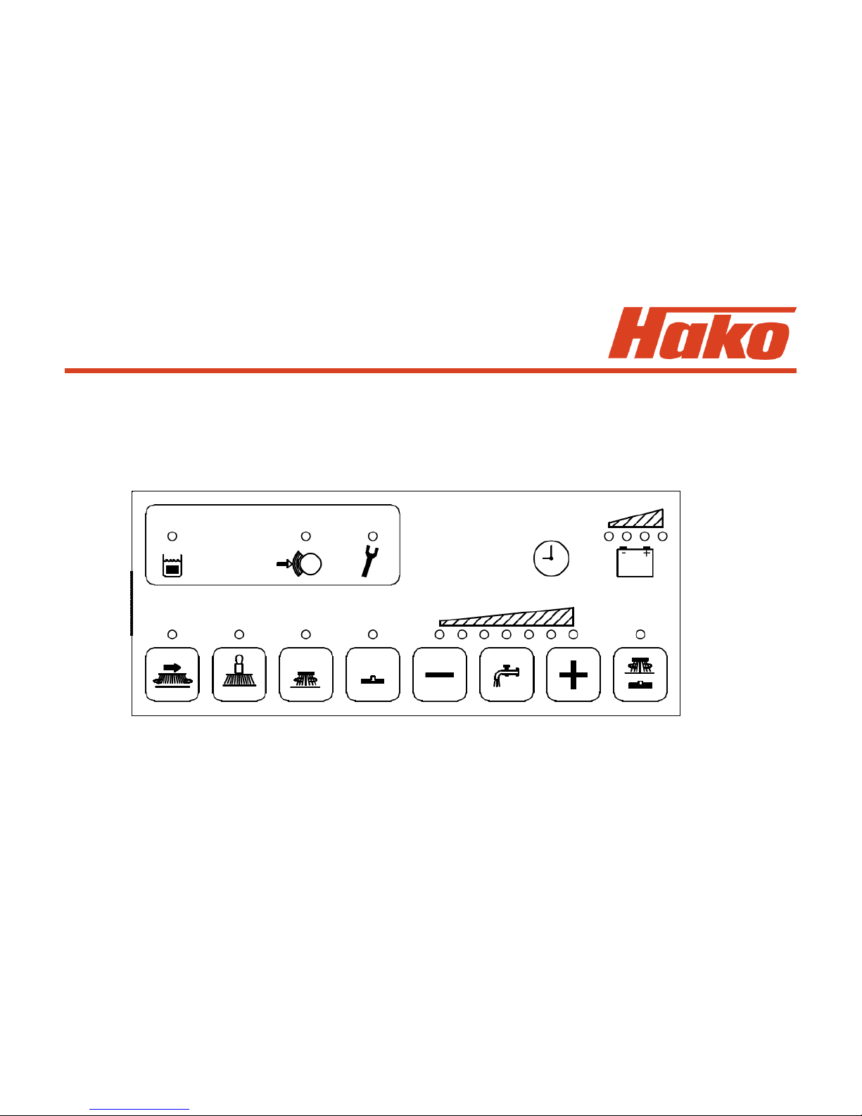
The picture shows the Hakomatic B1050 operator panel. Position of the programming
buttons is identical to those of the Hakomatic B1100. Only the icons differ due to the
different functional scope of this machine.
3. Machine Type Settings
B1050 PB & CB & PB 1230

Foil 20
Entry into programming
1. Switch off machine by key switch
2. Simultaneously press "G" and "H" and hold depressed, then switch on key switch
3. Hold depressed both buttons as long as the software version is displayed then
release buttons
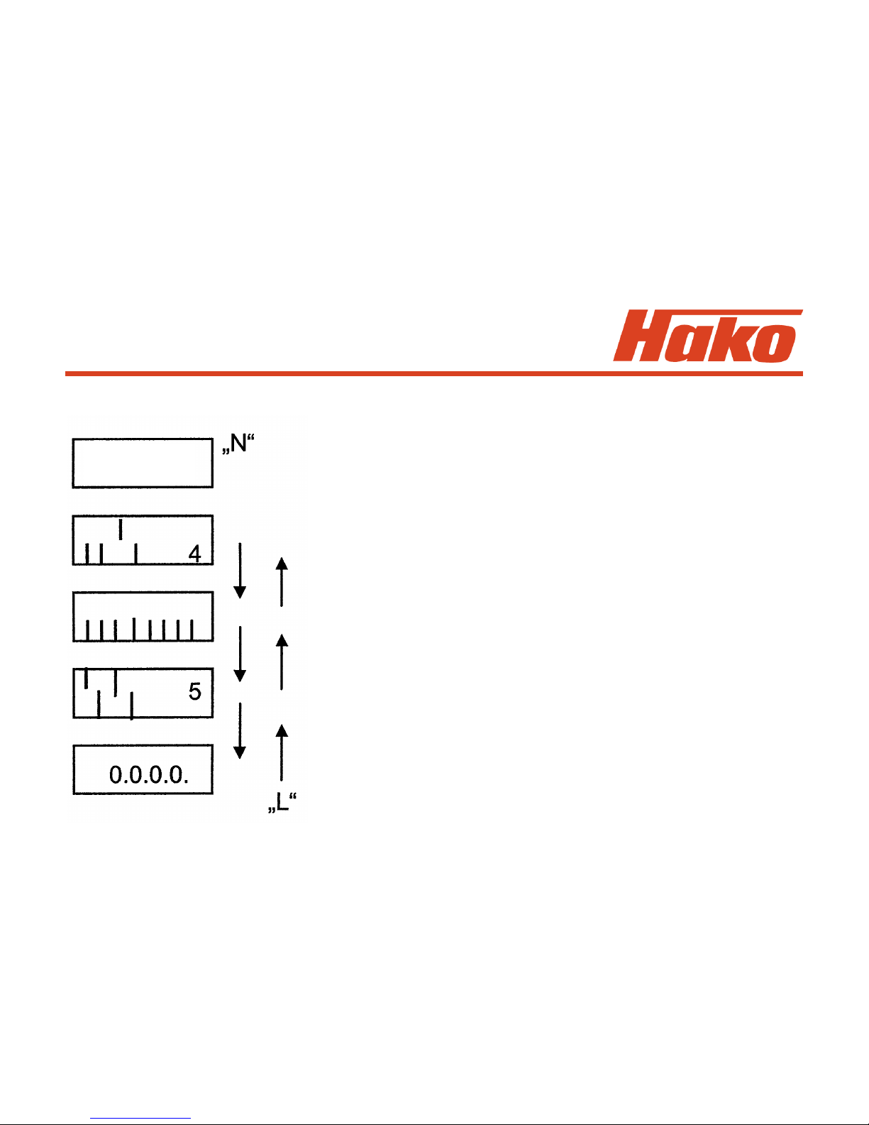
Display of set machine type then appears automatically. Use the “N” button to proceed
to display of set options and display of TSG setting or then to display of last
(remedied) error. Use the “L” button to return to previous display.
Quit programme any time by switching OFF the key switch.
3. Machine Type Settings
Foil 21
3. Machine Type Settings
Software version, automatic change to next
display
Set machine: 4 means B 1100; 11 means B 1050
13 means B1050 PB 1230;
14 means B1100 PB 1230
Set options
TSG setting
Display last error and reset
4020

Foil 22
3. Machine Type Settings
Control electronics
A1.X2
B
C
A
B1100 B1050 PB/CB B1050PB 1230
B1100-PB 1230

Foil 23
3.1 Check And Set
Machine Type
1. Make sure to have the correct machine type set. Use the Dip switch A on the
control electronics for setting (see foil 22)
2. For the B1100 machine, the bars no. 1, 2, 4 are to set in bottom and the bar no. 3 in
top position. This setting is a prerequisite for display of the cipher 4.
For the B1100 PB1230 machine, the bars no. 2, 3, 4 are to set in top and the bar 1
in bottom position. This setting is a prerequisite for display of the cipher 14.
For the B1050 machine, the bar no. 3 is to set in bottom and the bars 1, 2 and 4 in
top position. This setting is a prerequisite for display of the cipher 11.
For the B1050 TB 1230 machine, the bar no. 2 is to set in bottom and the bars
1, 3 and 4 in top position. This setting is a prerequisite for display of the cipher 13.
3. If other ciphers appear, modify combination at the Dip switch.
B 1100 1: OFF B 1100 1: OFF B 1050 1: ON B 1050 1: ON
2: OFF PB1230 2: ON PB / CB 2: ON PB 1230 2: OFF
3: ON 3: ON 3: OFF 3: ON
4: OFF 4: ON 4: ON 4: ON

Foil 24
3.2 Check And Set
Options
1. Setting each option in the machine is required at the Dip switch B (see p. 22)
on the control electronics.
2. The Dip switches are assigned as follows:
1: Cleaning agent dosage (B1100 &B1100PB 1230) (set = “ON”)
2: SWA (B1100 only) (set = “ON”)
3: Side brush (B1100 & B1050PB) (set = “ON”)
4: Tool (B1100 suction only) (set to “OFF”)
Tool (B1100 PB1230 & B1050PB / CB (set = “ON”)
and B1050 PB 1230 Spraying and suction)
5: Pre-sweeper (B1100 & B1050CB* (set = “ON”)
and B1100PB1230)
6: Cylindrical brush deck (B1050 only) (set = “ON”)
7 - 8: not assigned, i.e. “OFF”
* - for the B1050CB the side broom is activated.
3. An option is set if the Dip switch is set to ON.

Foil 25
3.3 Check And Set
TSG
1. The TSG has to be set in any case to the correct battery type.
2. When fitting other battery types, modify TSG setting as described below by
using Dip switch C on the control electronics
(see p. 22)
3. Dip switch 4 is to set to 36 V (OFF).
Set the TSG according to the following table. (No. 5 - PzS - is the default setting)

Foil 26
3.3 Check And Set
TSG
“1” means ON; “0” means OFF
The addition “foreign” indicates batteries which are not delivered by Hako.
Reset voltage for the TSG: approx. 38.5V.
This voltage is required to reset the TSG capacity to 100%.
Caution: as far as maintenance-free gel batteries are concerned, the difference
between Sonnenschein and Deta is no longer made and setting depends on the
battery type. Setting 6 for GIV batteries and setting 7 for PzV batteries, irrespective
of the manufacturer. (For historical reasons, the designations Sonnenschein and
Deta remain in the documents).
The adjustments 0 and 1 (GiS USA) are for the use with US manufactured batteries
only.

Foil 27
3.3 Check And Set
TSG
GiS and GiV are Grid plate batteries,
PzS and PzV are Tubular plate batteries,
GiV and PzV are maintenance free batteries
in Gel-Technologie,
GiS and PzS are vented, low maintenance batteries with liquid electrolyte.
For block batteries the following short terms are also used:
GiS = FF
GiV = GF-Y; GF-V
PzS = FT
Trough batteries are available as following types:
EPzS and EPzV

Foil 28
3.4 TSG Error 3211
TSG - Remarks on the error 3211
The controller receives data from the TSG module in serial form and transmission of a telegram
takes one second. The 3211 error occurs when two telegrams with the same contents are not
received within 5 seconds and this equally is the case if there is no transmission at all.
Apart from an actual defect of the TSG the following causes are possible for this error message:
No voltage supplied to the TSG (MK controller: A1:X2.1 + 4)
TSG is in auto test mode: battery DIP switch set to off-off-off or on-off-off (1-2-3) -
from Software revision 4.020 on, this adjustments are used for US-american
batteries
After occurrence of the 3211 error it is also possible to use the LED of the TSG to detect
functioning of data transmission since the TSG bar lights as soon as two telegrams with the same
contents have been successfully transmitted within 5 seconds. In all other cases, the bar does not
light.

Folie 29
3.5 View And Delete
Last Error
View
1. Press “N” button three times; then a 4-digit error code with blinking dots appears
(last error occurred and remedied)
2. Quit programme by switching OFF key switch (do not switch OFF key switch
when proceeding to point “Delete”)
Delete
1. Press “O” button and hold depressed as long as the display changes to 0.0.0.0.
2. Release button, switch key switch OFF and on again
3. The software version appears then and changes to normal hourmeter display
4. It is possible at any time and as described under “View” to read out the last
occurred error from the memory and view it since the error code is saved there
5. Quit programme by switching OFF key switch

Foil 30
4. Programming
Different Procedures
Programming of different procedures of cleaning functions depending on
the direction switch (check and set)
(For setting of the B 1050, it is the position of buttons which is decisive and not the
icon on the operator panel)

Foil 31
4. Programming
Different Procedures
Check
1. Switch off machine by key switch
2. Simultaneously press "N" and "O" buttons and hold depressed, then switch on
key switch
3. Hold both buttons depressed as long as the software version appears in the
display then release both buttons
4. Viewing the different programmes is possible by pressing the button “L” (down)
or the button “N” (up).
5. The active programme is marked by a dash in front of the cipher
6. Quit programme by switching OFF key switch (do not switch OFF key switch
when proceeding to point “Set”)
Set
1. Use the “L” or “N” button to select the desired programme
2. Press the “O” button and hold depressed until the dash appears in front of the
cipher. The programme then is saved and active
3. Quit programme by switching OFF key switch
Foil 32
4.1 Programme Functions
Precondition for functioning of the following programmes is that “Brushes” and/or
“Suction" and/or “Sweep” are ON. All programmes allow normal cleaning and suction
in ‘forward' accelerator position; for the 'Neutral' and 'Reverse‘ accelerator positions,
however, differences apply and are listed in the following table.
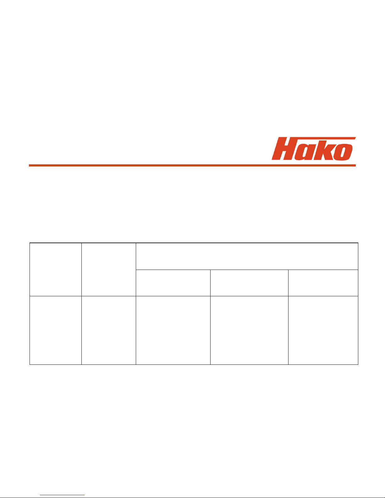
Programme Accelerator Function according to
code position/ accelerator position/direction switch
Direction Brush head Squeegee Broom
switch + Water (B1100 only)
Neutral Brushes and Suction remains Broom remains
water ON ON ON
1
Reverse Brushes and
water ON Lift squeegee Broom remains
ON

Foil 33
4.1 Programme Functions
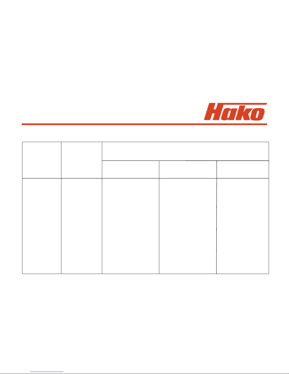
Programme Accelerator Function according to
code position/ accelerator position/direction switch
Direction Brush head Squeegee Broom
switch + Water (B1100 only)
Neutral Brushes and Lift squeegee Broom remains
water ON ON
2
Reverse Brushes and Lift squeegee Broom remains
water ON ON
Neutral Brushes and Suction remains Broom remains
water OFF ON ON
3
Reverse Brushes and Lift squeegee Broom remains
water ON ON

Foil 34
4.1 Programme Functions
Programme Accelerator Function according to
code position/ accelerator position/direction switch
Direction Brush head Squeegee Broom
switch + Water (B1100 only)
Neutral Brushes and Lift squeegee Broom off and
water OFF, lifted up
lift brush
head
4
Reverse Brushes and Lift squeegee Broom off and
water OFF, lifted up
lift brush
head
Neutral Brushes and Lift squeegee Broom remains
water OFF ON
5
Reverse Brushes and Lift squeegee Broom remains
water ON ON
Foil 35
4.1 Programme Functions
Programme Accelerator Function according to
code position/ accelerator position/direction switch
Direction Brush head Squeegee Broom
switch + Water (B1100 only)
Neutral Brushes and Lift squeegee Broom OFF and
water OFF, (delay lifted up
of 1 second for
6 brushes to avoid
(B 1100 only) the brushes from
& B1100 being switched OFF
PB 1230) when changing
from forward to
reverse ride)
Reverse Brushes and Lift squeegee Broom OFF and
water ON lifted up

Foil 36
4.1 Programme Functions
When the selected function of water supply, brush or suction function or the green
Hakomatic button is switched off by changed accelerator position, the function-related
LED blinks.
“ON” always means ‘switched ON’ and ‘lowered‘.
“OFF” only means ‘switched OFF’, ‘lifted’ is additionally indicated

Foil 37
5. Specific Customer
Settings
(Display of last error and selection of water stage, cleaning agent, SWA,
side brush, filter)
The settings described in this step can be modified according to customer
requirements. Factory settings need not be adopted.
For setting of the B 1050, it is the position of buttons which is decisive and not the
icon on the operator panel.

Foil 38
5. Specific Customer
Settings
Entry into programming
1. Switch off machine by key switch
2. Simultaneously press ”G" and "O" buttons and hold depressed, then switch on
key switch
3. Hold both buttons depressed as long as the software version appears in the
display, then release both buttons
Then the programmed settings for the following points are displayed automatically:
Display of last (remedied) error upon switching ON: yes / no
Water stage at start of cleaning: last selected stage/ always medium stage
Switch on cleaning agent together with switching ON water: yes / no (B 1100 & B1100 PB1230)
Water stage for Scrubbing and suction: last selected stage/ always medium stage
(B1050PB / B1050CB / B1050 PB 1230)
Switch over to SWA upon water ON: clear water / SWA (B 1100 only)
Switch on side brush/side broom together with switching ON scrubbing: yes / no (B1050PB/CB)
Switch on side brush together with switching ON scrubbing: yes / no (B 1100 only)
Filter shaking: in interval / as long as button is depressed (B 1100 & B1100 PB 1230)
Switch on filter suction together with switching ON sweeping: yes / no (B 1100 & B1100 PB 1230)
Automatic filter shaking after sweeping: yes / no (B 1100 & B1100 PB 1230)

Foil 39
5. Specific Customer
Settings
(this is the Factory setting for the B1100)
Currently programmed setting
Filter (B 1100 only)
Side brush
SWA (B 1100 only)/Side broom/-brush with scrubbing
Cleaning agent (B 1100 only)/water stage at scrub/suct
Water stage
Error display

Foil 40
5.1 PPV1 (Display Of Last Error)
1. Select desired setting by “L” and “N” buttons
2. The corresponding bar starts blinking
3. Use “M” button to move the bar up and down
Up = ON = Error code (of the remedied error) will be displayed for 3 seconds
after switching on
Down = OFF = Error code (of the remedied error) will not be displayed
4. Save setting by pressing the green button (“O” button) as long as the dot appears
at the bottom right of the display

Foil 41
5.2 PPV2 (Water stage Upon
Start of cleaning)
1. Select desired setting by “L” and “N” buttons
2. The corresponding bar starts blinking
3. Use “M” button to move the bar up and down
Up = ON = last selected stage is set
Down = OFF = always the medium stage is set
4. Save setting by pressing the green button (“O” button) as long as the dot appears
at the bottom right of the display

Foil 42
5.3 PPV3 (Cleaning Agent /
Waterstage)
1. Select desired setting by “L” and “N” buttons
2. The corresponding bar starts blinking
3. Use “M” button to move the bar up and down
B1100 Up = ON = Cleaning agent is equally switched on
& B1100 PB 1230 Down = OFF = Cleaning agent is not switched on
B1050 Up = ON = Water stage for Scrubbing and suction: last
selected stage
Down = OFF = always the medium stage is set
4. Save setting by pressing the green button (“O” button) as long as the dot appears
at the bottom right of the display

Foil 43
5.4 PPV4 (Switch Over to SWA /
Side broom - side brush)
1. Select desired setting by “L” and “N” buttons
2. The corresponding bar starts blinking
3. Use “M” button to move the bar up and down
B1100 Up = ON = Switching to dirty water recycling (SWA)
Down = OFF = Switching to clear water
B1050 Up = ON = Switching on side broom / brush together
(not B1050 PB 1230) with scrubbing
Down = OFF = don´t switch on side broom / brush
4. Save setting by pressing the green button (“O” button) as long as the dot appears
at the bottom right of the display

Foil 44
1. Select desired setting by “L” and “N” buttons
2. The corresponding bar starts blinking
3. Use “M” button to move the bar up and down
Up = ON = side brush is equally switched on
Down = OFF = side brush is not switched on
4. Save setting by pressing the green button (“O” button) as long as the dot appears
at the bottom right of the display
5.5 PPV5 (Side Brush Upon
Switching On Scrubbing)
(B1100 only)

Foil 45
1. Select desired setting by “L” and “N” buttons
2. The corresponding bar starts blinking
3. Use “M” button to move the bar up and down
Up = ON = Filter shaking as long as button is depressed
Down = OFF = Filter shaking after switching on by button 3 times in intervals
4. Save setting by pressing the green button (“O” button) as long as the dot appears
at the bottom right of the display
5.6 PPV6 (Filter Shaking)
(B 1100 & B1100 PB 1230)

Foil 46
1. Select desired setting by “L” and “N” buttons
2. The corresponding bar starts blinking
3. Use “M” button to move the bar up and down
Up = ON = Filter suction is equally switched on
Down = OFF = Filter suction is not switched on
4. Save setting by pressing the green button (“O” button) as long as the dot appears
at the bottom right of the display
5.7 PPV7 (Filter Suction Upon
Switching On Sweeping
Mode) (B 1100 & B1100 PB 1230)

Foil 47
1. Select desired setting by “L” and “N” buttons
2. The corresponding bar starts blinking
3. Use “M” button to move the bar up and down
Up = ON = after a minimum of 2 minutes of sweeping, shaking is automatically
switched on upon end of sweeping
Down = OFF = shaking is not automatically switched on upon end of sweeping
4. Save setting by pressing the green button (“O” button) as long as the dot appears
at the bottom right of the display
5.8 PPV8 (Automatic Filter Shaking
After Sweeping)
(B 1100 & B1100 PB 1230)

Foil 48
6. Settings On Module
The settings on the modules have an influence on load values of the electronic
circuit-breakers and the module coding.

Foil 49
6.1 Module 1
As they have an influence on the load value of the electronic circuit breakers for the
brush head and squeegee lifting elements, the Dip switch settings have to be correct
on Module 1.
Dip switch setting:
1: OFF
2: OFF
Circuit-breaker values:
Brush head: 5.7 A
Squeegee: 5.7 A

Foil 50
6.2 Module 3
As they have an influence on the module coding and the load value of the electronic
circuit breakers for the pre-sweeper / side broom / side brush lifting elements,
the Dip switch settings have to be correct on Module 3.
Modul 3 Code A (pre-sweeper B 1100 &): Modul 3 Code C (3rd Brush):
(B 1100 PB 1230) (B 1050 TB 1230 & B1100 PB 1230)
(Side broom B 1050 CB only)
1: OFF 1: OFF
2: OFF 2: ON
3: OFF 3: OFF
4: OFF 4: OFF
electr. C-b.: 5.7 A electr. C-b: not required
Modul 3 Code D (Side brush):
(B1100 und B 1050 TB)
1: ON
2: ON
3: OFF
4: ON
electr. C-b: 1.9 A

Foil 51
7. Operator Panel Settings
(B 1100 only)
The Code A and B operator panels (pre-sweeper / side brush and Cleaning agent /
SWA) have to be correctly set - i.e. coded - on the Dip switch.
These operator panel are available only in the Hakomatic B1100 & B1100 PB 1230.
They are located under the right-hand operator panel of the machine.
Code A (Pre-sweeper/Side brush; A2 ): Code B (Cleaning agent / SWA; A10):
1: OFF 1: ON
2: OFF 2: OFF

Foil 52
8. Water Pump
8.1 Water Amounts
For checking function of the water pump, voltage for each of the stages can be
measured at Module 1 (A5:X2:6+7).
When using a True RMS device, having water in the tank and ensuring that suction
turbine is OFF, the values from the following table shall be obtained:
When using other than the indicated measuring devices, values may vary since
measured voltage is pulsed. Beyond that the value depends on battery voltage.
Here, measurement was done with charged battery presenting three green LED
lighting in the battery indication.
The voltage values in the table are given for the Hakomatic B1100 and B1050PB only.
Beyond that, evaluation of the actually delivered water amount is to be
preferred since voltage values only indicate whether water pump control is
operable or not.

Foil 53
8. Water Pump
without
Sidebrush
with
Sidebrush
Stage 1: xx V ca. 1,3 l/min ca. 2,7 l/min ca. 1,3 l/min ca. 1,0 l/min
Stage 2: ca. 5,7 V ca. 2,2 l/min ca. 3,3 l/min ca. 2,2 l/min ca. 1,0 l/min
Stage 3: ca. 7,4 V ca. 2,9 l/min ca. 3,9 l/min ca. 2,9 l/min ca. 1,0 l/min
Stage 4: ca. 8,9 V ca. 3,6 l/min ca. 4,4 l/min ca. 3,6 l/min ca. 1,0 l/min
Stage 5: ca. 12,0 V ca. 4,7 l/min ca. 5,5 l/min ca. 3,9 l/min ca. 1,0 l/min
Stage 6: ca. 14,7 V ca. 5,7 l/min ca. 6,4 l/min ca. 4,1 l/min ca. 1,0 l/min
Stage 7: ca. 20,0 V ca. 7,5 l/min ca. 8,2 l/min ca. 4,4 l/min ca. 1,0 l/min
Hakomatic B1100 / B1050PB
Hakomatic
B1050CB
Option Tool
Hakomatic B1050

Foil 54
8.2 Standstill Detection For
Water Pump
Automatic standstill detection for water pump:
The electronics offer a possibility for water pump protection if delivery of pump is
blocked.
When the pump takes in water from the tank but cannot deliver it to the brushes,
a pressure builds up downstream the pump. Without protection by the electronics,
the pump would continue delivery against this pressure and could be damaged.
The electronics detects interruption of free delivery of the pump and automatically
switches off the pump for 2 seconds.
After these 2 seconds, pump is briefly switched on with simultaneous measurement
whether delivery then is free or whether water supply to brushes is still blocked.
When delivery of the pump is free, the selected stage remains ON; if counter-pressure
is still present, the pump again is switched OFF for 2 seconds. This procedure is
repeated until fault will be remedied.

Foil 55
9. Drive Controller
The light-emitting diodes (LED) are directly located on the electronics
LED indication Malfunction Remark
OFF Drive controller Voltage supply interrupted
without function Check fuses and wiring
ON Drive controller is Drive controller function
operable okay
2 signals Wrong start sequence Check accelerator and direction
switch as well as cabling
3 signals Output transistors Check wiring to drive motor;
do not connect or check carbon brushes;
no connection to if okay but error still present
drive motor replace drive controller
9.1 SEVCON Controller (Diagnostic LED)

Foil 56
9.1 SEVCON Controller
LED indication Malfunction Remark
4 signals Output transistors do Check wiring to drive motor
not connect or no and drive motor.
connection to drive motor Check direction switch and
direction contactors on drive
controller; if okay but signals
still present, replace drive
controller
5 signals Output transistors 160 A fuse blown, check
defective release signal from control
electronic; Check direction
switch and direction contactors
on drive controller; if okay but
signals still present, replace
replace drive controller

Foil 57
9.1 SEVCON Controller
LED indication Malfunction Remark
6 signals Accelerator or cable Check accelerator and wiring,
connection interrupted plugged connection eventually
loose; check direction switch
and drive potentiometer
switch
7 signals Battery voltage in- Measure voltage, check
sufficient, less than connections
13 Volts
8 signals Temperature of drive Is travel drive smooth?
electronics exceeded Is parking brake setting
(70 °C and higher) okay? Longer uphill rides?
Max. operating current
approx. 45 A

Foil 58
9.1.1 Signal Measurement at the
Drive Controller (SEVCON)
During test of the drive controller, the following points should be checked since
faultless operation of the drive controller is not possible without the described
signals applying accordingly.
The drive controller is designated by A6 in the circuit diagram and is supplied with
36 V even though some of the signals are 24-Volts signals.
The drive controller is a pulse controller activating the motor by the pulsed voltage.
In case of full throttle forward ride, battery voltage always applies at the motor.
1. Is F51-160A fuse okay?
2. Is battery voltage applying at drive controller?
3. Is battery minus connected at drive controller?
4. Is battery voltage applying at A6-X51:2 after switching key switch ON?

Foil 59
9.1.1 Signal Measurement at the
Drive Controller (SEVCON)
5. Cabling between accelerator potentiometer and drive controller okay?
Voltage measurement:
Green at A6-X51:8 (approx. 8.6V)
Red at A6-X51:9 (0-5V depending on potentiometer position)
Yellow at A6-X51:3 (approx. 0V)
Measured to battery minus
Resistance measurement (with machine switched off and
potentiometer disconnected):
Between green and red: approx. 5.7 kW Reducing to approx. 1.8 kW upon actuation
Between yellow and red: approx. 1.8 kW Increasing to approx. 5.7 kW upon actuation
Between yellow and green: approx. 4 kW Unchanged upon actuation
Caution: The potentiometer has a nominal value of 4 kW 20%. This means:
Due to the 20% tolerance, values may vary between 3.2 kW and 4.8 kW.
Depending on these tolerances, the measured values may increase or reduce
by up to 0.8 kW.

Foil 60
9.1.1 Signal Measurement at the
Drive Controller (SEVCON)
6. Is connection between A6:X51:3 and A1:X4:3&4 okay? Is battery minus equally
connected to A1:X4:3&4?
7. Is battery minus applying at A1:X3:1 after closing of key switch and seat contact
switch? Battery minus equally at S54:1? Is connection between A1:X3:1
and S54:1 okay? Only when battery minus is applying to S54 potentiometer
switch, the closed direction contactors can control the potentiometer switch and
the S53 direction switch.
8. Connection between direction switch and drive controller okay?
S53:B2 to A6-X51:4 (forward)
S53:B4 to A6-X51:5 (reverse)
9. Connection between direction switch and A1 control unit okay?
S53:A2 to A1:X8:4
S53:A4 to A1:X8:2
10. Are 24V applying at A1:X8:4 with “reverse” ride being selected?

Foil 61
9.1.1 Signal Measurement at the
Drive Controller (SEVCON)
11. Are 24V applying at A1:X8:2 after “forward” ride selected?
12. Is jumper in A1:X8 between Pin 1 and 3 and 5 okay?
13. Do switches S53 (direction) and S54 (potentiometer) operate faultlessly?
14. Is battery minus applying at A6-X51:4 with “forward” ride being selected
(potentiometer switch has to close)?
15. Is battery minus applying at A6-X51:5 with “reverse” ride being selected
(potentiometer switch has to close)?
16. Is battery minus no longer applying at A6-X51:11 with “reverse” ride being selected
(signal for speed reduction)?

Foil 62
9.1.1 Signal Measurement at the
Drive Controller (SEVCON)
17. Is cabling between drive controller and drive motor okay? Please check each
cable and their contacts. Do two wires contact via crimping > short-circuit?
18. Do direction contactors switch? Eventually proceed to activate each of them
directly.
19. Test with diagnostic device (general diagnostic devise and not that specific one for
drive controller as in the old version)

Foil 63
9.2 ZAPI Controller
The ZAPI controller has a diagnostic input. Unless not expressly indicated in the service
documents, modification of the default values and parameters is not admitted.
Contactor arrangement
A = Connector for contactor control and control inputs
B = Connector for console or alarm LED

Foil 64
9.2 ZAPI Controller
Description of control connections of the ZAPI controller
A1 RV1 Speed reduction 1; active if no positive voltage is applying
A2 IRE Emergency inversion acc. to Europ. standard; active if a pos. voltage is applying
A3 MT Tiller micro switch; active if a pos. voltage is applying
A4 NT2 Activation of neg. direction contactor forward ride (auto-stop),
Bypass contactor, general contactor or electric brake (standard)
A5 CH connected + (from key switch)
A6 IRZ Emergency inversion ("ZAPI standard"); active if no positive voltage is applying
A7 RV2 Speed reduction 2; active if no positive voltage is applying
A8 PT Activation positive for all contactors and micro-switches
A9 MA Micro-switch forward ride; active if a pos. voltage is applying
A10 MI Micro-switch reverse ride; active if a pos. voltage is applying
A11 NT1 Activation negative direction contactor reverse ride (auto-stop)
or both direction contactors (standard)
A12 NPOT Potentiometer negative
A13 CPOT Potentiometer arm
A14 PPOT Potentiometer positive (13V; output impedance 82Ohm)

Foil 65
9.2.1 ZAPI Controller
9.2.1 Automatic Monitoring of the Components
The micro-processor effectuates evaluation of basic controller functions.
This evaluation concerns:
•Check upon switching key switch ON:
Watch Dog, current sensor, power MOS FET, contactor activation (contactor driver),
direction switch, potentiometer connections, EEPROM)
•Check in standstill:
Watch Dog, current, power MOS FET, contactor activation (contactor driver), potentiometer
connections)
•Check during ride:
Watch Dog, current, power MOS FET, contactor activation (contactor driver), potentiometer
connections), closing and opening of contactors
•Permanent Monitoring:
Temperature, battery voltage
Eventual error messages are indicated by a blinking LED on connector B (section 2). The
number of blinks indicates the error type.

Foil 66
9.2.2 ZAPI Controller
9.2.2 Error Codes Displayed Via The LED
No. Blinks Message State* Remark
1) 1 WATCH-DOG A Error on electronics
2/3/4/5) 1 EEPROM A Error on electronics (EEprom)
6) 2 INCORRECT START B Direction actuated upon switching ON (or incorrect connection of IR)
7) 3 VMN LOW B MOSFET short-circuited
8) 3 VMN HIGH B Diodes short-circuited or direction contactor stuck
9) 4 VACC NOT OK B Potentiometer defective
10) 5 I=0 EVER A No current flow detectable during ride
11) 5 HIGH CURRENT A Current flow in rest mode
12) 6 PEDAL WIRE KO B Potentiometer wiring defective
13) 7 TEMPERATURE C Temperature > 76°C
15) 8 DRIVER 1 KO A NT1 driver short-circuited
16) 8 DRIVER 1 SIC KO A Contactor coil on NT1 short-circuited
17) 8 DRIVER 2 KO A NT2 driver short-circuited
18) 8 DRIVER 2 SIC KO A Contactor coil on NT2 short-circuited
19) 8 DRIVER SHORTED B Driver short-circuited (NT1)
20) 8 CONTACTOR OPEN B Contactor does not close
21) 9 POSITION HANDLE B Tiller micro-switch not actuated
22) 9 INVERSION B Deadman bounce key (IR) actuated or incorrectly wired
23) 9 FORW.+BACKW. B Both directions simultaneously actuated
24) Perman. light BATTERY C Battery discharge too important
* A = switch off system, remedy fault and switch on again
B = remedy fault and actuate direction again
C = display of state and eventual software-controlled measures

Foil 67
9.2.3 ZAPI Controller
1) WATCH-DOG
Test during rest state as well as during ride; internal self-test of hard- and software; replace controller
in case of fault alarm!
2) EEPROM PAR. KO
Error in the memory area containing values of the setting parameters. System switches off. If error
still persists after having switched key switch OFF and ON again, replace logic! If error disappears,
mind that the saved parameter values are deleted. (—> initial setting)
3) EEPROM CONF. KO
Error in the memory area containing the controller configuration data. If error still persists after having
switched key switch OFF and ON again, replace logic! If error disappears, mind that the saved
configuration is deleted. (—> initial setting)
9.2.3 Explanations On Displayed Error Messages

Foil 68
9.2.3 ZAPI Controller
4) EEPROM DATA KO
Data of the memory area controlling the hourmeter counter are corrupted. If alarm disappears after
having switched key switch OFF and ON again, mind that the hourmeter counter is reset to zero then.
5) EEPROM OFF LINE
Error in the non-volatile memory containing those values of the hourmeter counter concerning the
programmable parameters and the saved alarms. If error still persists after having switched key
switch OFF and ON again, replace controller!

Foil 69
9.2.3 ZAPI Controller
6) INCORRECT START
Corrupted order of sequence of start conditions. The system only starts if, depending on SAFETY
SWITCH programming, the following order is observed :
- Key switch - tiller micro-switch - direction switch (HANDLE)
- Key switch - direction switch (FREE)
- Key switch + seat switch - direction switch (SEAT)
Possible causes:
a) Direction or tiller micro-switch stuck.
b) Operator did not observe sequence.
c) Incorrect wiring.
If no external fault can be detected, replace controller!

Foil 70
9.2.3 ZAPI Controller
7) VMN LOW
Test in rest state and during ride up to VMN synchronised for 80%;
Voltage at VMN terminal normally equals 50% Vbatt if contactors are open. If this voltage is
insufficient (< 30% VBatt), an alarm will be output. Possible causes:
a) Main contactor (if available) does not close or is not connected at all
b) Short-circuit between VMN and -Batt terminals (metal particle or other)
(disconnect cable at VMN terminal, switch on, fault disappears)
c) Power MOSFET short-circuited or permanently activated by the logic;
disconnect cable at VMN terminal, switch on, fault persists, replace controller
d) Bypass contactor (if available) stuck or opens too slowly

Foil 71
9.2.3 ZAPI Controller
8) VMN HIGH
Test in rest state;
Voltage at VMN terminal normally equals 50% Vbatt if contactors are open. If this voltage is
excessive (> 70% VBatt), an alarm will be output. Possible causes :
a) One of the direction contactors is permanently closed due to mechanical blocking
or permanent activation (incorrect wiring of contactor coil)
b) Short-circuit between field and anchor coil of the motor
(disconnect cable at VMN terminal, switch on, Fault disappears, repair motor)
c) Incorrectly connected motor cable (check field and anchor wiring)
d) Power element of controller defective (suppressor or brake diodes short-circuited)
disconnect cable from VMN terminal, switch on, fault persists, replace controller

Foil 72
9.2.3 ZAPI Controller
9) VACC NOT OK
Test in rest state;
An alarm is displayed if the potentiometer voltage is higher than 1V, related to the saved minimum
value.
Possible causes:
a) One of the wires at the potentiometer or inductive sensor is broken.
b) Potentiometer or inductive sensor ist defective.
10) I=0 EVER
Test during ride;
If, during ride, the current does not exceed a determined minimum value, the error message appears
and the system switches off.
Possible causes :
a) Resistance of the motor is excessive due to motor defect or faulty carbon brush
contact
b) Current sensor is defective (replace controller)

Foil 73
9.2.3 ZAPI Controller
11) HIGH CURRENT
Test in rest state - contactor open;
If measured current is >50A, an alarm will be output and the system switches off. Current sensor is
defective (replace controller!)
12) PEDAL WIRE KO
If no voltage can be measured at the Pin NPOT (A12), to which the negative potentiometer terminal
is connected, an alarm is output. Possible causes:
a) Wire at PPOT (A14) terminal broken
b) Wire at NPOT (A12) terminal broken
c) Potentiometer defective (infinite resistance)
d) Potentiometer resistance >47 kOhm

Foil 74
9.2.3 ZAPI Controller
13) TEMPERATURE
This message indicates that temperatures has exceeded 76°C.
Maximum current is reduced by steps down to zero with a temperature of 86°C. Possible causes:
a) If the alarm is output directly after switching the system ON with a cold controller,
temperature monitoring is not working correctly (replace controller!)
b) If the alarm is output shortly after start of operation, heat is insufficiently
dissipated (check installation and fastening screws)
14) NO FULL COND.
Test at full speed;
If, at full speed, voltage at the VMN terminal is > 1/3 VBatt, this is an indication for a faulty diagnostic
circuit and the system switches off.
If the error persists, replace controller (logic unit).

Foil 75
9.2.3 ZAPI Controller
15) DRIVER 1 KO
If voltage at the NT1 terminal (A11) does not correspond to the desired value, an alarm is output and
the system switches off.
Possible causes:
a) Wire at the NT1 terminal (A11) broken or coil of the direction contactor
for reverse ride is defective.
b) Internal driver MOSFET short-circuited (replace controller!)
16) DRIVER 1 SIC KO
If current load at the contactor driver which activates the NT1 output (A11) is excessive, an alarm is
output and the system switches off.
Possible causes :
a) Short-circuit of the wire at NT1 terminal (A11) to +Batt
b) Coil of the connected contactor short-circuited or current consumption > 5A

Foil 76
9.2.3 ZAPI Controller
17) DRIVER 2 KO
If voltage at the NT2 terminal (A4) does not correspond to the desired value, an alarm is output and
the system switches off.
Possible causes:
a) Wire at the NT2 terminal (A4) broken or coil of the direction contactor
for forward ride is defective.
b) Internal driver MOSFET short-circuited (replace controller!)
18) DRIVER 2 SIC KO
If current load at the contactor driver which activates the NT2 output (A4) is excessive, an alarm is
output and the system switches off.
Possible causes :
a) Short-circuit of the wire at NT2 terminal (A4) to +Batt
b) Coil of the connected contactor short-circuited or current consumption > 5A

Foil 77
9.2.3 ZAPI Controller
19) DRIVER SHORTED (only with H0 STANDARD TRACT.)
If voltage at the NT1 terminal (A11) does not correspond to the desired value, an alarm is output and
the system switches off.
Possible causes:
a) Wire at the NT1 terminal (A11) broken or coil of the direction contactor
for forward or reverse ride is defective.
b) Internal driver MOSFET short-circuited (replace controller!)
20) CONTACTOR OPEN
Test upon actuation of a direction;
– It is checked whether the selected direction contactor closes by measuring the value of the VMN.
If this value is not correct, an alarm is output.
Proceed to the following instructions for remedy:

Foil 78
9.2.3 ZAPI Controller
When does error
occur?
1st test result 2nd test Result Error
Yes --> --> A1
Yes B1
No C1
Yes --> --> A2
Yes B2
No C2
Yes --> --> A3
Yes B3
No C3
In forward direction
only
Forward direction contactor
closes for 0.3 seconds and
then opens
No
For 0.3 seconds, a voltage
applies to the coil of the
forward direction contactor
In reverse direction
only
Reverse direction contactor
closes for 0.3 seconds and
then opens
No
For 0.3 seconds, a voltage
applies to the coil of the
reverse direction contactor
In both directions
Forward or reverse
direction contactor (as
actuated) closes for 0.3
seconds and then opens
No
For 0.3 seconds, a voltage
applies to the coil of the
forward or reverse direction
contactor (as actuated)

Folie 79
9.2.3 ZAPI Controller
A1 The NO contact of the forward direction contactor (TA) or the NC contact of the
reverse direction contactor (TI) is soiled or stuck.
Clean contacts or replace contactor group if required.
Clean NO contact of the forward
direction contactor (TA)
Clean NC contact of the reverse
direction contactor (TI)

Foil 80
9.2.3 ZAPI Controller
A2 The NC contact of the forward direction contactor (TA) or the NO contact of the
reverse direction contactor (TI) is soiled or stuck.
Clean contacts or replace contactor group if required.
Clean NC contact of the forward
direction contactor (TA)
Clean NO contact of the reverse
direction contactor (TI)

Foil 81
9.2.3 ZAPI Controller
A3 Connection to motor interrupted:
- Carbon brushes without contact to collector (Fig. 1)
- Connecting cable of carbon brush broken (Fig. 2)
- Motor winding defective or motor cable broken
- Inverted motor connection

Foil 82
9.2.3 ZAPI Controller
B1 The forward direction contactor is correctly activated but does not close.
- contactor coil defective, measure resistance by ohmmeter
- contact is mechanically blocked
- nominal voltage of contactor coil is higher than the battery voltage
B2 The reverse direction contactor is correctly activated but does not close.
- contactor coil defective, measure resistance by ohmmeter
- contact is mechanically blocked
- nominal voltage of contactor coil is higher than the battery voltage
B3 The forward or reverse direction contactor is correctly activated but does not close.
- coils of contactors are defective, measure resistance by ohmmeter
- contacts are mechanically blocked
- nominal voltage of contactor coils is higher than the battery voltage
C1 No voltage at the coil of the forward direction contactor. Check connector and cable of the
contactor coil to plus supply and to Pin A4 (NT2).
C2 No voltage at the coil of the reverse direction contactor. Check connector and cable of the
contactor coil to plus supply and to Pin A11 (NT1).
C3 No voltage at the coils of the forward and reverse direction contactors. Check connectors
and cables of the contactor coils to plus supply and to Pin A4 (NT2) and A11 (NT1).
Are the items C1, C2, C3 without fault, replace logic.

Foil 83
9.2.3 ZAPI Controller
21) POSITION HANDLE
If, upon switching ON, the tiller micro-switch has already been actuated, an error is output (only if
SAFETY SWITCH is programmed to HANDLE). Possible causes:
a) Tiller micro-switch stuck
b) Incorrect operation
22) INVERSION
If, upon switching ON, the emergency inversion switch (deadman) has been pressed, an alarm is
output. Possible causes:
a) Micro-switch for emergency inversion stuck
b) Incorrect operation
c) Incorrect wiring or programming
23) FORW - BACK
Fault is displayed if two directions are simultaneously active. Possible causes:
a) Wiring defective.
b) Direction micro-switch stuck. If none of the causes applies, replace logic!
24) BATTERY
Battery discharged, i.e. voltage has fallen below 60% of nominal voltage. An alarm is output. The
system switches off but may be restarted. In that case, maximum current will be reduced to 50% of
the programmed maximum current value.

Foil 84
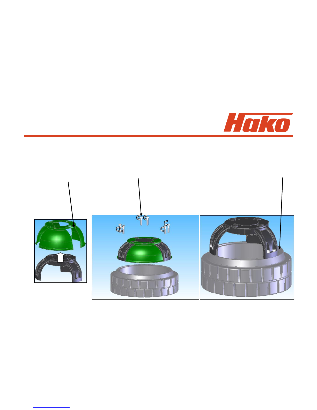
9.3 Drive Motor B1050 (Amer)
9.3.1 Tyre replacement
Unscrew the 4 screws of the hub
Warning! Lift up the machine so that the
tyre is not touching the ground
Screw the 4 pullers two by two (at 180°) in
the bracket until the hub is removed (Tool
PN 03502210)
Warning! Remove the 4 pullers
after this operation
Foil 85
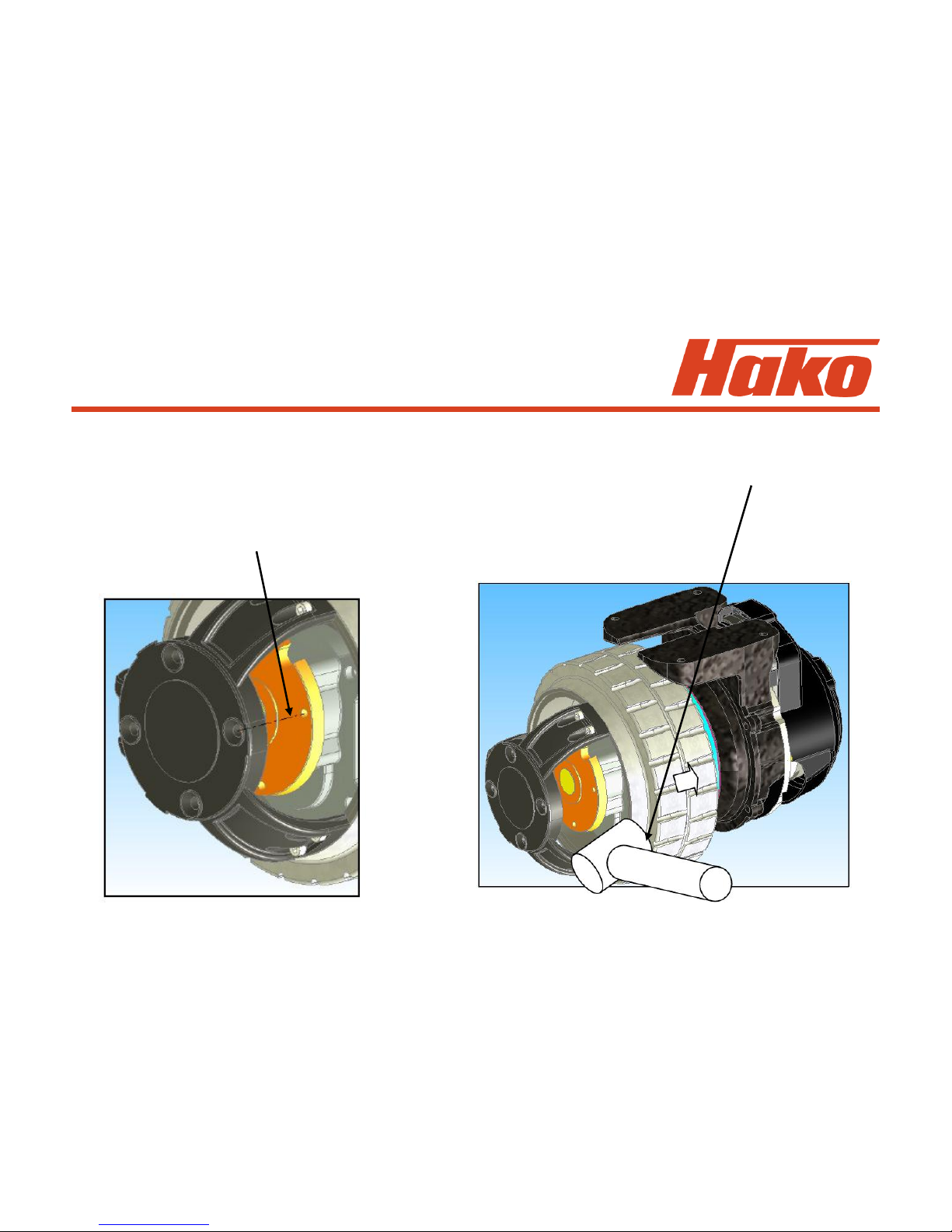
9.3 Drive Motor B1050 (Amer)
Remove the
plastic hub cover
Unscrew the 6 screws M6x30
tightening torque 16Nm ±10%
Replace the old tyre and re-assemble
the new tyre with the hub without the
plastic hub cover
Torque screw 16 Nm ± 10%
Foil 86
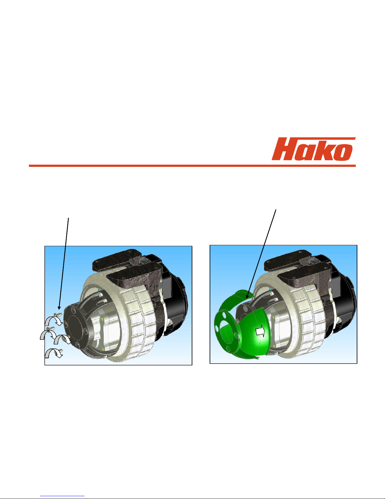
9.3 Drive Motor B1050 (Amer)
Install the wheel on the MTR11 by using
a plastic mallet
Warning! Check the radial position of the
hub with the inner disc during the
mounting
Tire puller kit (Tool PN 03502210)
Foil 87
9.3 Drive Motor B1050 (Amer)
Screw the 4 screws M8x20
tightening torque screw 22 Nm ±10%
Mount the plastic cover hub manualy
Foil 88
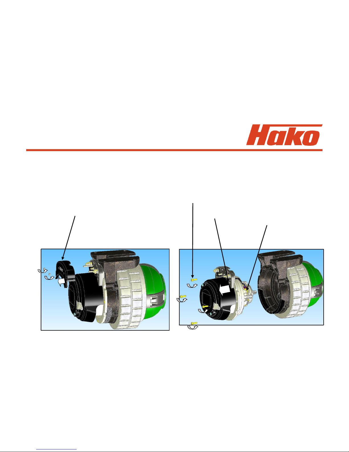
9.3.2 Drive Motor B1050 (Amer)
Check (every 1000 hours) and replacement (max. 1500 hours) of the
carbon brushes
•the wear out limit of the carbon brushes is 12 mm
Unscrew the 2 nuts.
After remove the terminal board cover.
Remove the 4 screws M6x20.
tightening torque 9.5Nm -10% +20%
Then remove the motor.
Replace the carbon brushes.
Foil 89
9.3.3 Diagnostic LED for Drive
control unit (Italsea)
Display / Flashes Alarm What To Do
Alarm A7
OVERCURRENT
Alarm A8
Power fuse/Relais
Power fuse or main
contactor damaged
Over-current: short circuit
Controller detects a failure on the external power
fuse or power connections. If controller repeats
this alarm and the power connections are ok,
replace it
Check the motor´s wires: if ok, and the controller
repeats this alarm, replace the controller
Alarm A6
POWER STAGE
Alarm A5
Over temperature
Alarm A4
Reference OUT of neutral
Move the potentiometer to neutral position or if it
is in neutral position yet, calibrate the speed
reference.
Thermal protection
Controllers power stage
damaged
replace the controller
Wait a few minutes and check the motor current
Potentiometer out of neutral
position at power-on
Alarm A3
Potentiometer Fault
Check the potentiometer and it´s wiring
Alarm A1
FORWARD switch ON
Alarm A2
BACHWARD switch ON
Forward switch closed at
power-on
Backward switch closed at
power on
Potentiometer fault
Put the speed reference to zero and open the
Forward switch
Put the speed reference to zero and open the
Backward switch

Foil 90
9.3.3 Diagnostic LED for Drive
control unit (Italsea)
Display / Flashes Alarm What To Do
Alarm A16
Forward and Backward
switch on
Both direction switches on
Check the direction switches and / or their
connections
Check the field output connections / wirings. If ok
replace controller
E²PROM fail
Check the settings: if the controller repeats this
alarm, replace it.
Alarm A14
E2PROM FAIL
Alarm A15
Field Fault
Check the input switch: this alarm will reset by
power-off. Input voltage at -A6:J2.6
Disable switch ON
Alarm A12
Disable ON
Alarm A13
KEY-OFF
Key-Off sequence detected
Check the key switch connections.
Input voltage at -A6:J2.15
Battery voltage higher than 45V: check the battery
Check the Motor working current
Armature: I
max
50A
Field: I
max
12A
Overload protection
(armature or field)
Alarm A11
Overload Current
Alarm A10
Overvoltage
Overvoltage
Alarm A9
Undervoltage
Undervoltage
Check battery charging level

Foil 91
10. Error Table With Information
On Service Display
Error code in Malfunction Remark
the display
1.2.5.2. Thermal switch Wire broken since NC activation?
Brush motor Measure operating current (approx. 12 A
1); 2); 3); 4); 5) for a motor when operated without in-
creased pressure and on Fama Famin)
Motor overload due to unfavourable floor-
brush-combination and/or permanent
ride with increased ground pressure?
1.2.5.5. Thermal switch Wire broken since NC activation?
3rd Brush motor Measure operating current (approx. 12 A
(Modul3 Code C) for a motor when operated without in-
4) ; 5) creased pressure and on Fama Famin)
Motor overload due to unfavourable floor-
brush-combination and/or permanent
ride with increased ground pressure?

Foil 92
10. Error Table With Information
On Service Display
Error code in Malfunction Remark
the display
1.2.6.1. Blocking protection Check 35 A fuse
Brush motor Measure operating current (approx. 12 A
(right and left) for a motor when operated without in-
1); 2); 3); 4); 5) creased pressure and on Fama Famin)
Motor overload due to unfavourable floor-
brush-combination and/or permanent
ride with increased ground pressure?
1.2.6.2. Blocking protection Check 35 A fuse
3rd Brush motor Measure operating current (approx. 12 A
(Modul3 Code C) for a motor when operated without in-
4); 5) creased pressure and on Fama Famin)
Motor overload due to unfavourable floor-
brush-combination and/or permanent
ride with increased ground pressure?

Foil 93
10. Error Table With Information
On Service Display
Error code in Malfunction Remark
the display
1.2.6.3. Electronic circuit-breaker Jammed? Lifting element stopped by
Brush lifting element limit stop before being switched off by
1); 2); 3); 4); 5) micro-switch? Check coding of
Module 1 Measure operating current
(approx. 3.5A max. during lifting)
1.3.5.1. Thermal switch Jammed? Permanent contact to border
Side brush during ride? Wire broken since NC
1); 2) activation? Check 35 A fuse; Measure
operating current (approx. 8 A max.)
1.3.6.1. Blocking protection Jammed? Permanent contact to border
Side brush during ride? Wire broken since NC
1); 2) activation? Check 35 A fuse; Measure
operating current (approx. 8 A max.)

Foil 94
10. Error Table With Information
On Service Display
Error code in Malfunction Remark
the display
1.3.6.2. Blocking protection Jammed? Lifting element stopped by
Lifting element limit stop before being switched off by
Side brush micro-switch? Check coding of
1); 2) Module 3 Code D Measure
operating current
(approx. 1.2A max. during lifting)
1.4.6.1. Electronic circuit-breaker Jammed? Lifting element stopped by
Lifting element limit stop before being switched off by
Squeegee micro-switch? Check coding of
1); 2); 3); 4); 5) Module 1 Measure operating current
(approx. 3.2A max. during lifting)

Foil 95
10. Error Table With Information
On Service Display
Error code in Malfunction Remark
the display
2.2.5.1. Thermal switch Thermal switch of Broom or Side brush
Broom (and thermal motor opened or cabling faulty?
switch Side brush Jammed? Measure operating current
Motor if new version (approx. 9.5 A max. on Fama Famin for
is fitted) broom motor) Wrong sweeping track
1); 5) width? Unfavourable floor-brush-
combination?
At machines equipped with the new side
brush version (Kit 105-736, side brush
motor PN 105-733): Is side brush setting
okay? Jammed? Measure operating
voltage (max. 2.5 A after approx.
10 minutes run) and approx. 100-110 rpm

Foil 96
10. Error Table With Information
On Service Display
Error code in Malfunction Remark
the display
2.2.6.1. Blocking protection Jammed? Check 35 A fuse
broom Measure operating current (approx. 9.5 A
1); 5) on Fama Famin floor), Sweeping track
adjustment (30 mm - 50 mm)
Unfavourable floor-broom combination?
2.2.6.2. Blocking protection Jammed? Does lifting element moves up
lifting element broom to dead stop before being switched off
1); 5) by micro switch? Check module coding
module 3 Code A switch S4 to OFF
Measure operating current
(approx. 3.3 A when lifting)

Foil 97
10. Error Table With Information
On Service Display
Error code in Malfunction Remark
the display
2.3.5.1. Thermal switch side Side broom setting okay?
broom left / right Jammed? Measure operating current
1); 3); 5) (max. 2.5 A after approx. 10 minutes run)
2.3.6.1. Blocking protection Side broom setting okay?
L-h side broom Jammed? Measure operating current
1); 3); 5) (max. 2.5 A after approx. 10 minutes run)
and approx. 100-110 rpm
2.3.6.2. Blocking protection Side broom setting okay?
R-h side broom Jammed? Measure operating current
1); 3); 5) (max. 2.5 A after approx. 10 minutes run)
and approx. 100-110 rpm

Foil 98
10. Error Table With Information
On Service Display
Error code in Malfunction Remark
the display
2.3.6.4. Blocking protection Jammed? Does lifting element moves up
lifting element side to dead stop before being switched off
broom by micro switch?
3)
3.1.6.1. Fuse Check 10 A / 80 V fuse. If code for
Module 1 blocking protection of lifting element for
1); 2); 3); 4); 5) brush or squeegee is indicated, check
these, check water pump; with SWA
equally check K2 and water pump (SWA)
check 35A fuse; measure operating
current of suction turbines
(approx. 19.5 A max. for one Motor)

Foil 99
10. Error Table With Information
On Service Display
Error code in Malfunction Remark
the display
3.1.6.2. Fuse Check all fuses F1(10 A / 80 V)
Module 3 Code A and F4-F7, check motors for filter
( for pre-sweeper) suction (F6 = 20A/80V),
1); 3); 5) shaking (F7 = 20A/80V), r-h (F4)
and l-h side broom (F5)
Caution: If old version of side broom
motor (PN 51-237) is still installed, the
F4 and F5 fuses are 20A/80V.
If new version of side brush motor
(PN 105-733) is already installed, the
F4 and F5 fuses are 10A/80V

Foil 100
10. Error Table With Information
On Service Display
Error code in Malfunction Remark
the display
3.1.6.5. Fuse Check all fuses F1(10 A / 80 V)
Module 3 Code C and F4-F7 (5A/80V)
( for 3rd brush)
4); 5)
 Loading...