


Operating Manual
Hakomatic B115R (7090.11/.21/.35/.41/.51/.81/.91)

2
Preface
Dear Customer,
We are certain that the excellent qualities of the vehicle will justify the faith
you have shown in us through your purchase.
Please read the Chapter "Safety Information" prior to starting the vehicle to
ensure it is operated and used safely.
Your safety, and that of others, basically lies in your ability to control and operate the vehicle. Before using the
equipment for the first time, read this
original manual thoroughly, act according to the information contained and
keep it in a safe place for future reference or subsequent owners. The operating manual contains all the most
important information regarding operation, maintenance and service.
Throughout this manual, texts which
concern safety are indicated by the corresponding danger pictogram. Should
you have any questions in respect of
the vehicle or operating instruction
manual, your authorized Hako dealer is
available to provide help at any time.
You are expressly advised that you
cannot base any legal claims on the information contained in this manual. Ensure only original spare parts are used
should any repairs be necessary. Only
such original spare parts warrant that
the equipment is reliably ready to use at
all times. We reserve the right to make
technical modifications in the interest of
further development.
Valid as of: September 2011
Hako-Werke GmbH
D-23843 Bad Oldesloe
Hamburger Str. 209-239
Tel. ++49 (04531) 8060
Intended use
The Hakomatic B115R is a scrubber
dryer for the wet cleaning of hard floors.
Any use beyond this is regarded as improper use. The manufacturer is not
considered liable for any damage resulting from improper use; the user is
solely responsible for all the potential
risks involved. Intended use also includes maintaining and observing the
operating, maintenance and repair conditions prescribed by the manufacturer.
The Hakomatic B115R may only be operated, serviced and repaired by personnel who are familiar with the work
involved and are aware of the risks.
The applicable accident prevention
laws must be observed and any generally accepted health and safety directives must be maintained. The
manufacturer is not deemed liable for
any damage resulting from unauthorized modifications to the vehicle.
Introduction

3
Based on the conception, design and
construction of the model introduced
onto the market by us, the machine
complies with the applicable basic safety and health requirements stipulated in
the EC directives (refer to the Declaration of Conformity). The EC Declaration
of Conformity is no longer considered
valid in the event of modifications to the
machine not authorized by us.
The manufacturer is not deemed liable
for any damage resulting from unauthorized modifications to the vehicle.
Notes on warranty
The terms defined in the purchase
agreement apply. Claims for compensation related to damage are excluded
from the terms of warranty when the
damage is the result of failure to observe regulations concerning service
and maintenance. Maintenance work
must be performed by authorized Hako
service centers and confirmed in the
“Maintenance Report” which serves as
a warranty logbook.
The following are excluded from the
terms of warranty: wear and tear
through overuse, defective fuses, improper handling and use or unauthor-
ized modifications. Claims under the
terms of warranty are annulled when
damage occurs to the vehicle resulting
from the use of parts or accessories not
explicitly approved by us or from failure
to observe maintenance regulations.
Acceptance of the vehicle
The vehicle must be inspected directly
after delivery for signs of transport damage. Replacements for transport damage will be made when confirmation is
provided immediately by the transporting company with regard to the damage
and send the damage report to us together with the consignment note.
Introduction

4
Table of Contents
Preface. . . . . . . . . . . . . . . . . . 2
Intended use . . . . . . . . . . . . . 2
Notes on warranty . . . . . . . . . 3
Acceptance of the vehicle . . . 3
1 Safety Information . . . . . . . . 6
1.1 Safety and warning labels . . . 6
1.2 General information . . . . . . . . 7
1.3 Operating information. . . . . . . 7
1.4 Maintenance information . . . . 8
1.5 Particular risks . . . . . . . . . . . . 9
1.6 Environmental protection . . . 10
1.7 Labels on the vehicle . . . . . . 11
2 Operation . . . . . . . . . . . . . . 15
2.1 Unpacking . . . . . . . . . . . . . . 15
2.2 Prior to starting up for the first
time . . . . . . . . . . . . . . . . . . . 15
2.2.1 Instruction. . . . . . . . . . . . . . . 15
2.2.2 Assembling the squeegee . . 15
2.2.3 Battery type . . . . . . . . . . . . . 16
2.2.4 Installing the trough battery . 17
2.2.5 Installing the driving/block
battery . . . . . . . . . . . . . . . . . 18
2.2.6 Checking the battery plugs. . 19
2.2.7 Initial battery charge. . . . . . . 19
2.3 Cleaning operation . . . . . . . . 20
2.3.1 Check the battery charge. . . 21
2.3.2 Charging the battery. . . . . . . 21
2.3.3 Emptying the waste water tank
23
2.3.4 Filling the clean water tank. . 24
2.3.5 Adjusting the driver's seat . . 25
2.3.6 Switching the vehicle on. . . . 26
2.3.7 Charge status indicator . . . . 27
2.3.8 Switching the vehicle off. . . . 28
2.3.9 After completing cleaning. . . 29
2.4 Service code table . . . . . . . . 30
2.5 Loading and transporting . . . 31
2.6 Special equipment and
accessories . . . . . . . . . . . . . 32
3 Operation . . . . . . . . . . . . . . 34
3.1 Method of operation . . . . . . . 34
3.2 Operating and indicator
elements. . . . . . . . . . . . . . . . 35
3.2.1 Left-hand operating panel . . 35
3.2.2 Right-hand operating panel . 37
3.2.3 On the vehicle . . . . . . . . . . . 43
4 Technical Data . . . . . . . . . . 46
5 Maintenance and
Service . . . . . . . . . . . . . . . . 49
5.1 Hako system maintenance. . 49
5.2 Proof of Maintenance . . . . . 50
5.3 Maintenance Plan . . . . . . . . 51
5.4 Battery system . . . . . . . . . . . 55
5.4.1 Water filling system . . . . . . . 56
5.4.2 Charge status indicator (TSG) .
56
5.4.3 Servicing the driving batteries .
56
5.4.4 Disposing of batteries. . . . . . 56
5.5 Waste water and clean water
tank . . . . . . . . . . . . . . . . . . . 57
5.5.1 Cleaning the clean water tank .
58
5.5.2 Cleaning the clean water filter .
58
5.5.3 Cleaning the waste water tank.
58
5.6 Disk brush head . . . . . . . . . . 59
5.6.1 Cleaning the brushes . . . . . . 60
5.6.2 Changing the brushes . . . . . 60
5.7 Cylindrical brush head . . . . . 61
5.7.1 Emptying the dirt hopper . . . 62

5
Table of Contents
5.7.2 Disassembling the brushes . 62
5.7.3 Installing the brushes . . . . . . 62
5.8 Deflector. . . . . . . . . . . . . . . . 63
5.8.1 Pivoting the deflector away . 63
5.8.2 Changing the deflector rubber .
63
5.9 Squeegee. . . . . . . . . . . . . . . 64
5.9.1 Cleaning the squeegee . . . . 65
5.9.2 Changing the sealing strips . 65
5.9.3 Adjusting the sealing strips. . 66
EC Declaration of Conformity
69

6
Safety Information
1 Safety Information
1.1 Safety and warning labels
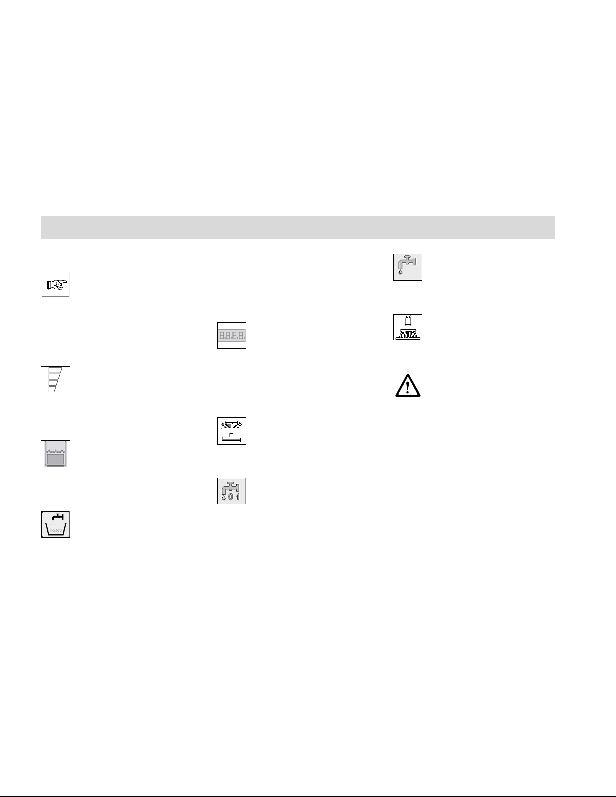
All information related to personal safety, safety of the vehicle and environmental protection are assigned the
following symbols throughout the operating manual:
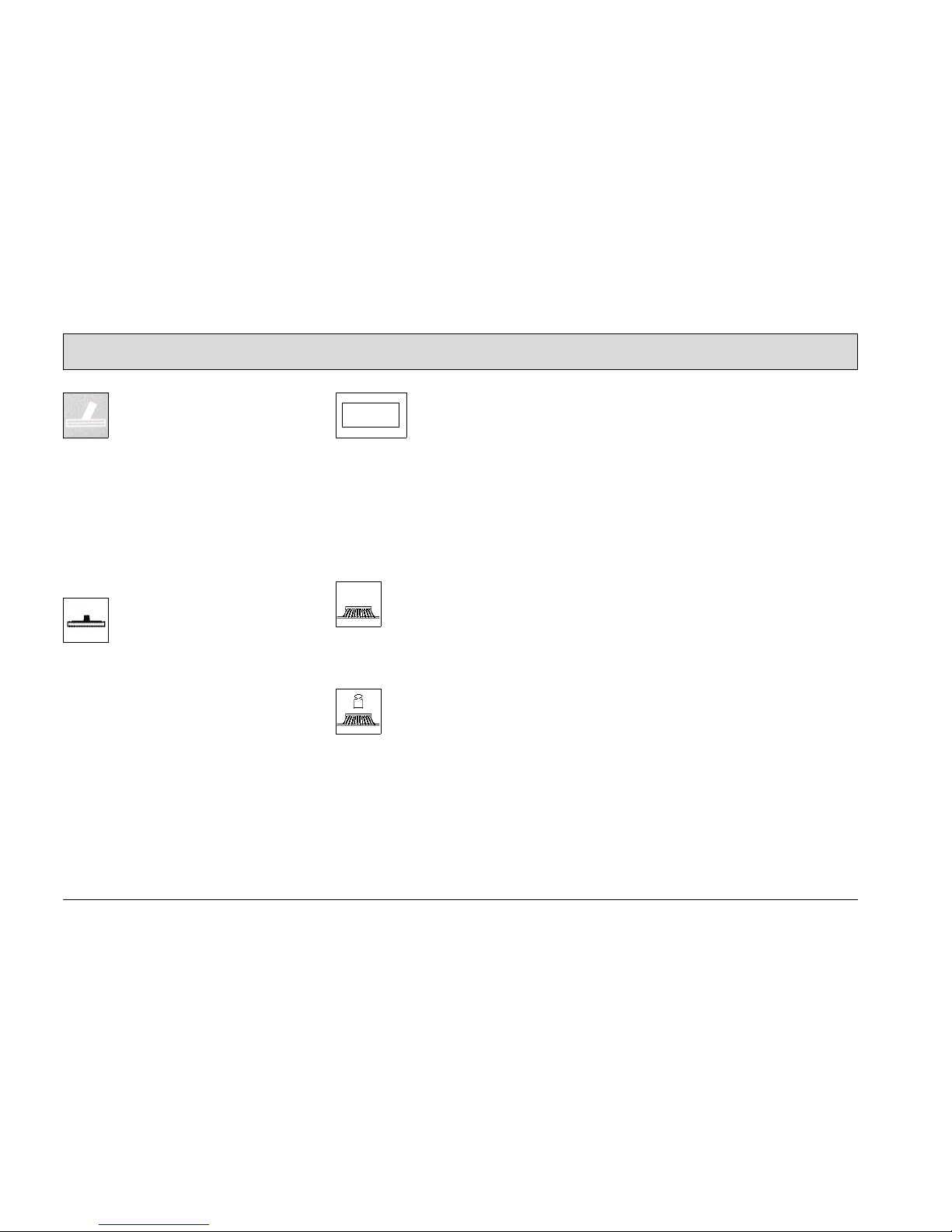
Symbol Hazardous for ... Definition
Danger persons
or property
Safety information to prevent the development of hazardous situations resulting from ignoring or failing to
follow instructions or prescribed work procedures.
Note the equipment Important information on handling the equipment in
order to maintain its functionality.
Ecological hazard the environment Ecological hazard through the use of substances
which represent a potential hazard to health and the
environment.

7
Safety Information
1.2 General information
• In addition to the information provid-
ed in this operating manual, all the
legally applicable health and safety
provisions must be observed.
• Before starting up the vehicle for the
first time, read the operating manual
supplied with it thoroughly as well as
any separate manuals provided with
additional or attachment devices and
observe all the information during
work.
• The vehicle may only be operated,
serviced and repaired by personnel
trained by Hako technical experts.
• Particular attention should be paid to
the information regarding safety.
Technical expertise is the key to preventing errors when operating the
equipment and ensuring trouble-free
operation.
• The operating manual must always
be kept at the operating location of
the vehicle and, as a result, should
kept in a safe place on the vehicle.
• If the equipment is sold or rented out,
these documents should be transferred to the new owner/operator.
The transfer should be confirmed!
• The warning labels attached to the
equipment provide important information concerning safe operation.
Labels which are illegible or missing
must be replaced.
• Original spare parts must be used to
ensure safety.
1.3 Operating information
• Before starting the vehicle up for the
first time, the battery to be used must
be fully charged, properly, by implementing the initial battery charge
routine. Please pay attention to the
operating manual provided with the
charging unit as well as the manual
from the battery manufacturer. Hako
assumes no liability for damage to
the battery caused by a fault when
the battery is charged for the first
time.
• Check the operational safety of the
vehicle each time before starting it
up! Clear any faults immediately!
• Before starting work, the operator
must be fully familiar with all adjustment, operating and control elements as well as their respective
function! It is too late to do this when
the vehicle is actually in operation!
• Always wear heavy duty, non-slip
footwear when working with the vehicle.
• The vehicle may only be driven and
the equipment used on those surfaces which have been approved by the
contractor or person appointed by
him.

8
Safety Information
• When using the vehicle, it is essential to pay attention to third parties,
especially children.
• Start driving immediately after
switching on the brush head drive
otherwise imprints of the brush could
be produced on the floor. Always
raise the brush head before driving
over thresholds.
• Only use cleaning agents suitable for
the vendor (non-foaming) and observe all the use, disposal and warning information provided by the
cleaning agent manufacturer.
• Never vacuum up any explosive fluids, undiluted acids or solvents! Examples of these include gasoline,
paint thinner and heating oil, which
can form explosive gases or mixtures when swirled up with the vacuumed air, and also acetone,
undiluted acids and solvents if they
corrode materials in the vehicle.
• For safety reasons, the driver's seat
is equipped with a seat contact
switch. The vehicle can only be started when the operator is sitting on the
driver's seat. The function of the seat
contact switch must not be bypassed.
• The vehicle is not suitable for clearing up hazardous, inflammable or
explosive fluids, dust or substances.
• It is forbidden to use the vehicle in
potentially explosive atmospheres.
• It is forbidden to transport persons or
heavy objects.
• It is forbidden to tow machines or operate as a trailer.
• Remove the ignition key to prevent
unauthorized use of the vehicle.
• When driving the vehicle to the area
of use, the squeegee and brush
head must be raised. The style of
driving must be adapted to the local
conditions.
• The vehicle has been conceived for
use on level surfaces with a maximum gradient of 2%.
• Drive slowly on wet ground due to
the risk of skidding, particularly when
cornering. Drive especially slowly
when cornering while driving downhill.
• Only drive uphill on gradients up to
10% for maximally 1 minute and with
the utmost care.
1.4 Maintenance information
• Operating personnel must complete
the necessary daily and weekly
maintenance work. All other maintenance work must be completed at
your nearest authorized Hako service center.
• The maintenance work and maintenance intervals prescribed in the operating manual must be adhered to.
• Suitable tools must be used for
cleaning and maintenance work.
• The vehicle must be inspected by a
recognized technical expert in respect of operational safety, within
the terms of the applicable accident
prevention laws, at reasonable intervals (we recommend at least once a
year) and following modification or
repairs .
• Spare parts must comply with the
minimum technical requirements
stipulated by the manufacturer! This
is ensured by the use of original
spare parts.
• The vehicle and motors must be
switched off prior to cleaning or servicing it or to replacing parts.
• Remove the ignition key to prevent
unauthorized use of the vehicle.

9
Safety Information
• Always disconnect the battery plug
before starting any work on the electrical installation.
• It is not permitted to clean the vehicle
with a pressure washer or steam
blaster.
• It is not permitted to use aggressive
and corrosive cleaning agents.
• Allow the vehicle to dry after being
cleaned, e.g. over the weekend.
• Only start the vehicle up when all the
safety equipment has been installed
and brought to its protecting position.
• When working in the area of the
raised waste water tank, it must be
opened fully to prevent it accidentally
slamming shut.
1.5 Particular risks
Electronics
• Only use original fuses with the prescribed amperage.
• In the case of defects in the electrical
installation, switch the vehicle off immediately and clear the fault.
• Work on the electrical equipment
may only be carried out by electricians who have received the necessary training and in accordance with
the electrical engineering regulations.
• The vehicle's electrical equipment
must be inspected/checked at regular intervals. Defects, such as loose
connections and cable damage,
must be rectified immediately.
Batteries
• Observe the information in the operating manual provided by the battery
manufacturer.
• Batteries may only be handled and
changed by properly skilled maintenance personnel.
• Due to a change in the center of
gravity, only approved batteries may
be installed at the intended position.
• Never lay any metallic objects or
tools on batteries - risk of short circuit!
• Ensure sufficient ventilation in the
charging area when charging the
batteries – risk of explosion!
• To prevent creeping currents,
always keep the batteries clean and
dry and protect from becoming
soiled, e.g. by metal dust.
• Batteries must not be connected or
disconnected when live.
• When closing the seat console, pay
attention that no cables are damaged.
• It is forbidden to eat, drink and
smoke in battery charging rooms.
• Wash you hands thoroughly after
handling batteries.
• For further safety information, see
supplementary sheet 88-60-2556 Notes on driving batteries.
Safety equipment
• Never operate the vehicle without
the hood being closed and locked
(safety regulation)!

10
Safety Information
1.6 Environmental protection
• Personnel must have the necessary
skills when working with substances
which represent a risk to health and
the environment, e.g. oils and lubricants.
• Always observe the applicable legal
regulations and local directives when
disposing of refuse, waste water and
cleaning agents, also refer to the
German Water Resources Act
(WHG).
• Used batteries must not be thrown in
the household waste.

11
Safety Information
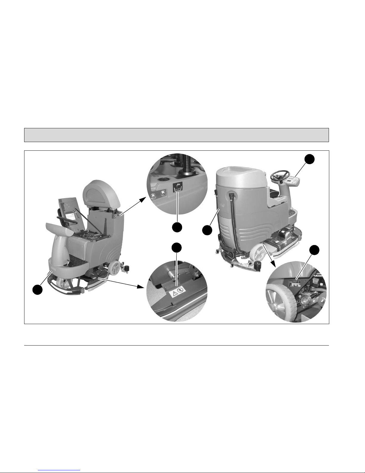
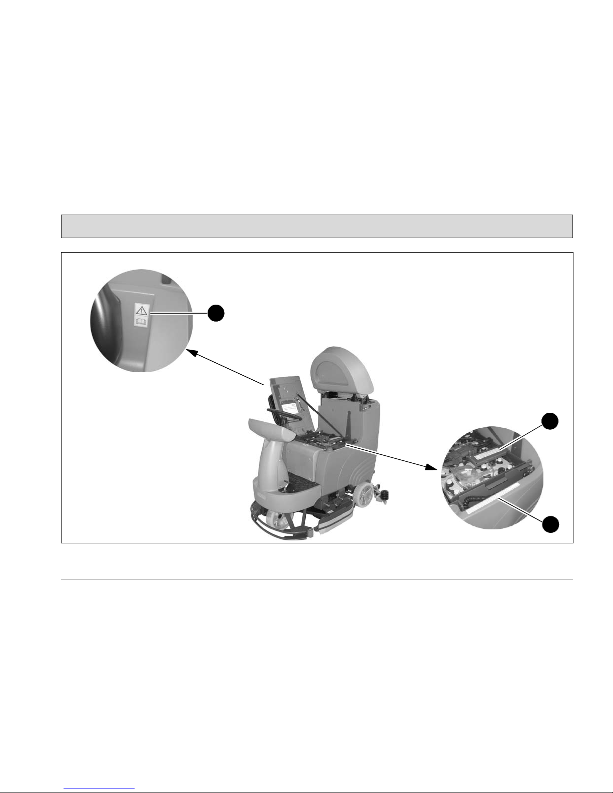
1.7 Labels on the vehicle
The following safety and warning labels
are attached to the vehicle where easily
legible. Missing or illegible labels must
be replaced immediately.
Company logo (Fig. 1/1)
Machine model (Fig. 1/2)
Rating plate (Fig. 1/3)
Water temperature, max. 50° (Fig. 1/4)
Label: Do not step on deflectors!
(Fig. 1/5)
Read and observe the operating
manual (Fig. 2/6)
Label: Explosive gases! (Fig. 2/7)
Label: Water overflow! (Fig. 2/8)
Waste water drainage (Fig. 3/9)
Clean water drainage (Fig. 3/10)
Label: Working width (Fig. 3/11)
Hakomatic B115R
XXX/XX
12
Safety Information
Fig.1
1
1
2
3
4
5
13
Safety Information
Fig.2
6
7
8

14
Safety Information
Fig.3
10
9
11

15
Operation
2 Operation
2.1 Unpacking
Remove the packaging and take the
Hakomatic B115R from the pallet after
loosening the tightening straps.
2.2 Prior to starting up for the
first time
2.2.1 Instruction
Operators must receive instruction before the vehicle is put into service. Only
technicians from your local authorized
Hako dealer are allowed to provide initial instruction on the machine. The
manufacturing plant will notify the dealer immediately after delivering the vehicle and the dealer will contact you to
arrange a date.
2.2.2 Assembling the squeegee
1. Use the star-shaped knobs (Fig. 4/1)
to fix the squeegee on the squeegee
lift (Fig. 4/2).
2. Connect the suction hose (Fig. 4/3)
to the nozzle (Fig. 4/4).
Fig.4
1 4
1
23

16
Operation
2.2.3 Battery type
Various batteries can be selected for
use with the Hakomatic B115R. Refer
to the table for the various battery types
and it must then be set in the Configuration menu. The settings can only be
made at an authorized Hako service
center!
Battery type Order no.
Trough battery 24 Volt/320 Ah - PzS low-maintenance
Trough battery 24 Volt/280 Ah - PzV maintenance-free
Driving battery 6 Volt/180 Ah - GiV maintenance-free
Block battery 6 Volt/240 Ah - GiV maintenance-free
745002
7451
7411
7401

17
Operation
2.2.4 Installing the trough battery
1. Switch off the vehicle with the key
switch and secure it by applying the
parking brake.
2. Open the seat console (Fig. 5/1).
3. Install the battery (Fig. 5/2) in the
battery trough accordance with illustration.
Replacing/Installing is only
possible with the aid of a crane
and appropriate lifting gear.
Please read the information
provided in the operating manual of the battery manufacturer. Trough batteries weigh up
to 280 kg. For reasons of safety, we strongly recommend
having this work completed at
an authorized Hako service
center.
4. Check the battery plug (Fig. 5/3),
refer to Section 2.2.6.
Fig.5
1
2
3
18
Operation
2.2.5 Installing the driving/block
battery
1. Switch off the vehicle with the key
switch and secure it by applying the
parking brake.
2. Open the seat console (Fig. 6/1).
3. Position the batteries in the battery
tray in accordance with the figure.
Replacing/Installing is only
possible with the aid of appropriate lifting gear. Please read
the information provided in the
operating manual of the battery manufacturer. For reasons
of safety, we strongly recommend having this work completed at an authorized Hako
service center.
4. Connect the battery poles in accor-
dance with the connection diagram
(Fig. 6/2).
5. Pay attention they are firmly fixed
and grease the poles.
6. Check the battery plug (Fig. 6/3),
refer to Section 2.2.6.
Fig.6
1
2
3

19
Operation
2.2.6 Checking the battery plugs
The battery plugs (Fig. 7/1 and 2) on
the vehicle, batteries and stationary
chargers must be coded with the colored coding pins (Fig. 7/3) according to
the battery and nominal voltage. The
connectors on the charger are coded at
the factory according to the charge
characteristic curve so that on changing
the charge characteristic curve (according to the battery), the connector coding
must be changed.
Fig.7
Connector coding
Socket housing of the battery:
• Gray for wet batteries
• Green for maintenance-free gel batteries
Connector body on the vehicle:
• Yellow for both battery types
Voltage coding
Insert the coding pin (Fig. 7/3) so that
the nominal voltage can be read
through the window in the housing.
Always select the same nominal voltage for the socket and connector.
The following three conditions must be
fulfilled for the complete system:
1. The voltage coding must be the
same for all connectors and sockets.
2. The color of the coding pin in the
vehicle is yellow.
3. The color of the coding pin in the
charger connector (vehicles without
built-in charger) complies with the
battery plug.
2.2.7 Initial battery charge
Before starting the vehicle up
for the first time, the batteries
to be used must be fully
charged, properly, by implementing the initial battery
charge routine. Please pay attention to the operating manual
provided with the charging unit
as well as the manual from the
battery manufacturer. Hako
assumes no liability for damage to the battery caused by a
fault when the battery is
charged for the first time.
1
24 V
24 V
36 V
36 V
3
2
20
Operation
2.3 Cleaning operation
Read and follow the safety information in Chapter 1 before
operating the vehicle.
1. Check the parking space for signs of
leaks. Hoses, lines and tanks must
show no signs of leaks or damage.
2. Check the battery charge, refer to
Section 2.3.1.
The current charge status appears in the indicator field.
Charge the battery, if necessary, refer to Section 2.3.2.
3. Drain off the waste water tank, refer
to Section 2.3.3.
You are informed the waste
water tank is full via the indicator field.
4. Fill the clean water tank, refer to Section 2.3.4.
The maximum temperature is
50°C.
5. Adjust the driver's seat, refer to Section 2.3.5.
6. Lock the side deflector.
7. Switch on the vehicle with the key
switch and set the required driving
direction using the driving direction
selection switch, refer to Section
2.3.6.
The operating hour counter
displays the software version,
the last service code (if applicable) and operating hours in
succession. Service code
table, refer to Section 2.4
8. Press the button for the brush head
and squeegee.
The vehicle is ready for operation.
9. Press the button for the clean water
supply.
The clean water supply is activated.
10.Press the button for the clean water
dosing.
The clean water quantity is set.
11.If necessary, press the button for
brush pressure adjustment.
The brush pressure is activated.
Start driving immediately after
switching on the brush head
drive otherwise imprints of the
brush could be produced on
the floor!
Always raise the brush head
before driving over thresholds!
21
Operation
2.3.1 Check the battery charge
The batteries are charged using the integrated battery charger (Fig. 8/1). The
batteries can be charged as soon as the
first field in the charge status indicator
(Fig. 8/2) goes out, at the latest, however, after the cleaning functions have
switched off (all fields go out).
2.3.2 Charging the battery
1. Move the vehicle to a piece of level
ground, switch it off and apply the
parking brake.
2. Open the seat console and connect
the battery charger to the power outlet using the power cable (Fig. 8/3).
The seat console (Fig. 8/4)
must be open during the charging process!
Never let batteries stand
around in a discharged state
but recharge them immediately!
Fig.8
3
4
1
2

22
Operation
Checking the charging process
You can monitor the charging process
by means of the LED on the integrated
charger. When the charging process is
started (by connecting the power plug
or battery connection), the green LED
flashes (according to the characteristic
curve set). While the charging program
is active, the yellow LED (Fig. 9/1) lights
up. When the charging program has
ended, the green LED (Fig. 9/2) lights
up. A trickle charge is then supplied.
The battery is again ready for use.
The vehicle cannot be switched on
while the integrated charger is in operation!
The red LED (Fig. 9/3) signals an error.
• Invalid characteristic curve - red LED
flashes fast
• Battery error (no battery, charging
time exceeded) - red LED flashes
slowly
• Device too hot - red LED lights up
(error is not automatically reset)
Fig.9
1
2
3

23
Operation
2.3.3 Emptying the waste water
tank
Empty the waste water tank (Fig. 10/1)
daily, as necessary or following the
acoustic warning and indicator in the
display.
1. Drive to an appropriate disposal
point.
2. Park the vehicle so that the draining
hose (Fig. 10/2) reaches the drain in
the floor.
3. Switch off the vehicle.
Observe the applicable laws
and local regulations when disposing of cleaning agents!
4. Remove the draining hose from the
holder and open the plug (Fig. 10/3)
by turning it 90° counterclockwise.
Empty the waste water tank completely.
Fig.10
1
2
3

24
Operation
2.3.4 Filling the clean water tank
1. Fill the clean water tank (Fig. 11/1)
before starting work or as necessary.
Park the vehicle on a level floor area.
2. Open the tank cap (Fig. 11/2) and fill
the clean water tank through the
opening (Fig. 11/3) (max. temperature 50°C).
3. Mix the cleaning agent in accordance with the manufacturer's instructions.
Only use cleaning agents approved by Hako for their vendors (non-foaming). These
products meet the requirements stipulated in the washing and cleaning agent directive (WRMG - Wasch- und
Reinigungsmittelgesetzes).
Fig.11
1
2
3

25
Operation
2.3.5 Adjusting the driver's seat
The driver's seat (Fig. 12/1) can be adjusted with the lever (Fig. 12/2) so that
the driver can sit comfortably with all the
operating elements within easy reach.
The vehicle is equipped with
an electronically monitored
seat contact switch. Damage
or manipulation of the seat
contact switch causes the vehicle to be locked against use.
Fig.12
2
1

26
Operation
2.3.6 Switching the vehicle on
For safety reasons, the driver's
seat is equipped with a seat
contact switch. The vehicle can
only be started when the operator is sitting on the driver's
seat.
1. Pull the power plug (Fig. 13/1) from
the socket and place it in the holding
recess.
2. All control levers must be in their
neutral position.
3. Switch on the vehicle with the key
switch (Fig. 13/3) and set the required direction using the driving direction selection switch (Fig. 13/5).
The operating hour counter
(Fig. 13/4) displays the software version, the last service code (if applicable) and operating hours in
succession. Service code table, refer
to Section 2.4.
Fig.13
1
24
3
5

27
Operation
2.3.7 Charge status indicator
The charge status indicator (Fig. 14/1)
provides information on the current
charge status of the batteries up to the
total discharge limit. If the batteries are
fully charged when the vehicle is
switched on, all four fields light up under
battery icon. While the vehicle is in operation, the fields go out according to
the discharge of the battery power.
When the top three fields have gone
out, the permissible low discharge level
is reached. The bottom field begins to
flash and an acoustic warning signal is
issued. All the cleaning units are
switched off after three minutes, the
vacuuming function following a 15 second rundown time. The vehicle can then
be driven at reduced driving speed to a
charging point for the batteries. For information on charging the batteries, refer to Section 2.3.2
If the vehicle is switched on, an
acoustic warning signal continues to be issued. When the
battery charging process has
been completed, the status is
cleared and the vehicle is
again ready to operate.
Fig.14
1
28
Operation
2.3.8 Switching the vehicle off
1. Release the accelerator (Fig. 15/1)
slowly to its zero position. The vehicle slows until it eventually stops.
You can decelerate more quickly by
applying the vehicle's brake
(Fig. 15/3).
2. Move the driving direction selector
switch (Fig. 15/2) to its zero position.
3. Apply the brake (Fig. 15/3) to its end
position and then release it to lock it.
4. Switch off the clean function.
5. Switch the vehicle off with the key
switch (Fig. 15/4).
Remove the ignition key when
getting off the vehicle to prevent unauthorized use.
Fig.15
1
3
4
2

29
Operation
2.3.9 After completing cleaning
1. Drive to an appropriate maintenance
area.
2. Stop the vehicle, raise the brush
head and squeegee and remove the
key.
3. Empty the waste water tank and
flush it.
Observe the applicable laws
and local regulations when disposing of cleaning agents.
4. Check the clean water filter
(Fig. 16/1).
5. Check the sealing strips (Fig. 16/2)
and suction hose (Fig. 16/3).
6. Check the electrical equipment,
functions and settings.
7. For information on charging the battery, refer to Section 2.3.1
8. Clean the machine. If the machine is
to be shutdown for a longer period,
the clean water tank must be emptied.
It is not permitted to clean the
vehicle with a pressure washer
or steam blaster.
Fig.16
1
2
3

30
Operation
2.4 Service code table
In the case of system errors, a four-digit
error code appears in the operating
panel in addition to the service indicator
(wrench symbol).
The dots in the service code flash.
Clear the fault or note down the service
code and inform your authorized Hako
dealer.
When the cause is cleared, the error
must finally be acknowledged by turning the key switch OFF/ON.
Code Fault Cause Solution
1.2.5.2. Brushes stop Foreign bodies between brush
and shaft
• Check the brushes for foreign bodies
and remove them, as necessary.
1.2.6.1. Brushes stop Foreign bodies block the brush • Check the brushes for foreign bodies
and remove them, as necessary.
1.2.6.3. Brush attachment and brush
motor are switched off
Foreign bodies between the
brush head and vehicle.
• Check the brush head for foreign bodies
and remove them, as necessary.
1.4.6.1. Squeegee lift and suction
turbine are switched off
• Foreign bodies between the
squeegee and vehicle.
• Squeegee is jammed
• Check the holding attachment for foreign
bodies and remove them, as necessary.
• Free the squeegee.
3.3.1.1. Service interval has expired Refer to maintenance schedule
3.4.5.1. Cleaning function is
switched off
• Parking brake is applied
• Foreign bodies are interfering
with the drive chain or drive
wheels
• Release the parking brake.
• Remove the foreign bodies

31
Operation
2.5 Loading and transporting
When the vehicle is loaded for
transport or driven to its point
of use, the squeegee and
brush head must be raised.
Loading
Take the weight of the vehicle into account when loading it, refer to Section
"Technical Data".
Transporting
When the vehicle is to be transported
on another vehicle or trailer, it must be
secured against rolling away. Lash the
machine down securely. Fix the vehicle
in place with lashing straps.

32
Operation
2.6 Special equipment and
accessories
Refer to the table below for the order
numbers of the special equipment and
accessory parts.
Only the special equipment
and accessory parts listed here
may be used. Please contact
the authorized Hako dealer responsible for you.
Special equipment for Hakomatic B115R Order no.
Warning equipment with flashing light and acoustic signal
Working lights
Comfort seat
Mop holder and toolkit net for cleaning tools
Large particle sieve for waste water tank
Large particle sieve for clean water tank
Onboard chemical dosing system
Tool connection fittings
Vacuuming and spraying hose
Floor scrubbing and vacuuming tool
7091
7092
7093
7095
7060
7679
767845
737602
7766
7009

33
Operation
Accessories for disk brushes Pcs. TB 650 TB 750 TB 900
Light to medium soiling - PPN 0.5
Light to medium soiling, structured floors - K901
Light to medium soiling, structured floors - SIC PA 600
Medium to heavy soiling - PPN 0.8
Medium to heavy soiling - SIC PA 6/600
Very heavy soiling / basic cleaning, SIC PA 6/180
Extremely heavy soiling / basic cleaning, SIC PA 6.12/120
Specially for use on structured multi-storey car park floors
2
2
2
2
2
2
2
2
7513
7517
7515
730702
7519
7521
7514
7518
7516
7308
7520
7522
7684
7544
7547
7317
7543
7545
7546
7686
Accessories for super-pads with drive plates Pcs. TB 650 TB 750 TB 900
Light soiling - red
Routine cleaning - brown
Basic cleaning and heavy soiling - black
Medium soiling and routine cleaning - green
Poly pads (microfiber pads)
Also necessary: drive plates (pad holders) with center lock
5
5
5
5
2
2
752505
752705
752905
787105
708502
7523
752605
752805
753005
787205
708602
7524
755105
754905
755005
787405
708802
7548
Accessories for cylindrical brushes Pcs. WZB 600 WZB 700 WZB 850
Light to medium - PA 6/0.7 mm
Medium to heavy, structured floors - SIC PA 6.12/500
Very heavy soiling / basic cleaning - SIC PA 6.12/180
1
1
1
7021
7022
7023
7096
7099
7094
7681
7682
7683
34
Operation
3 Operation
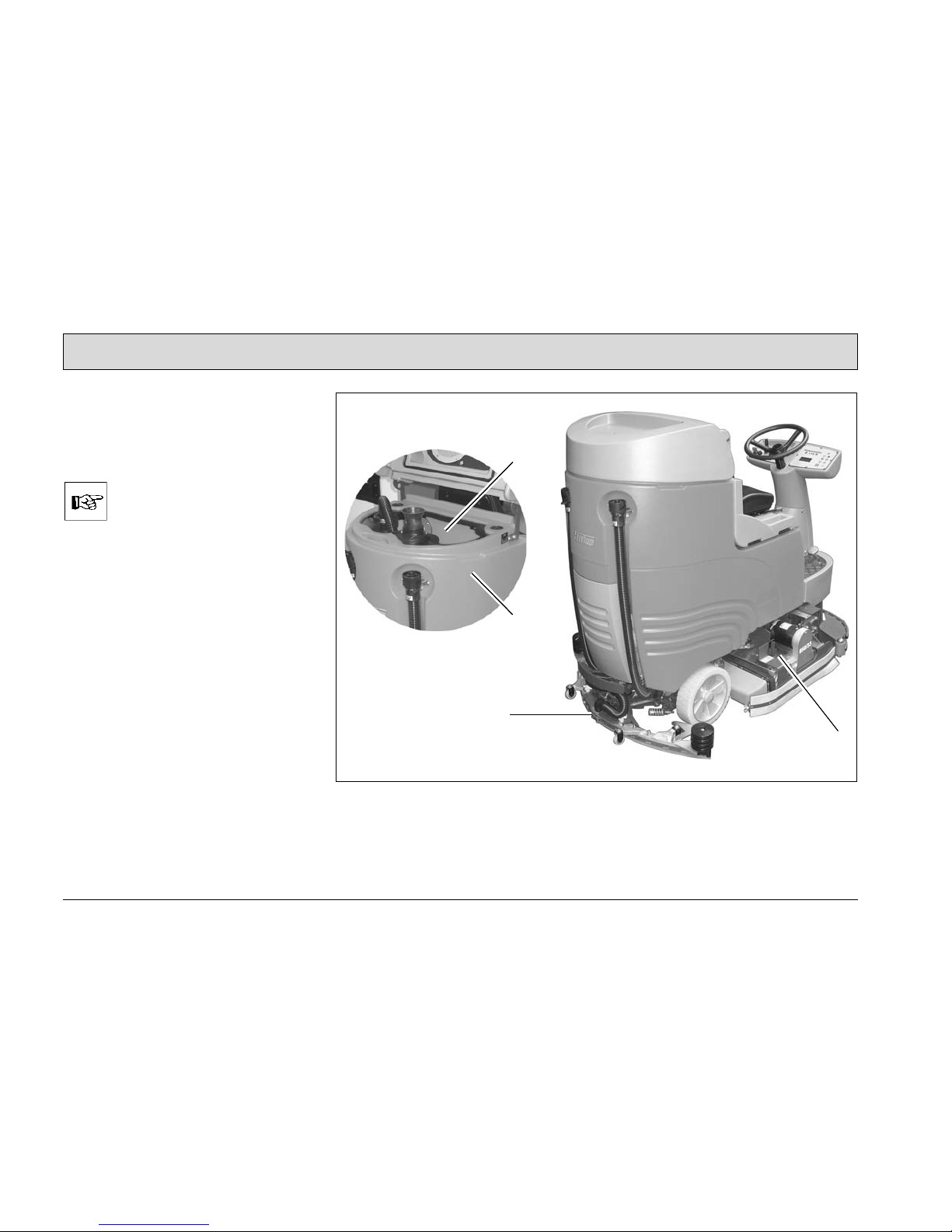
3.1 Method of operation
The Hakomatic B115R is a scrubberdrier for the wet cleaning of hard floors.
The vehicle can be supplied fitted with a disk brush head or
cylindrical brush head. This
manual contains illustrations of
both versions.
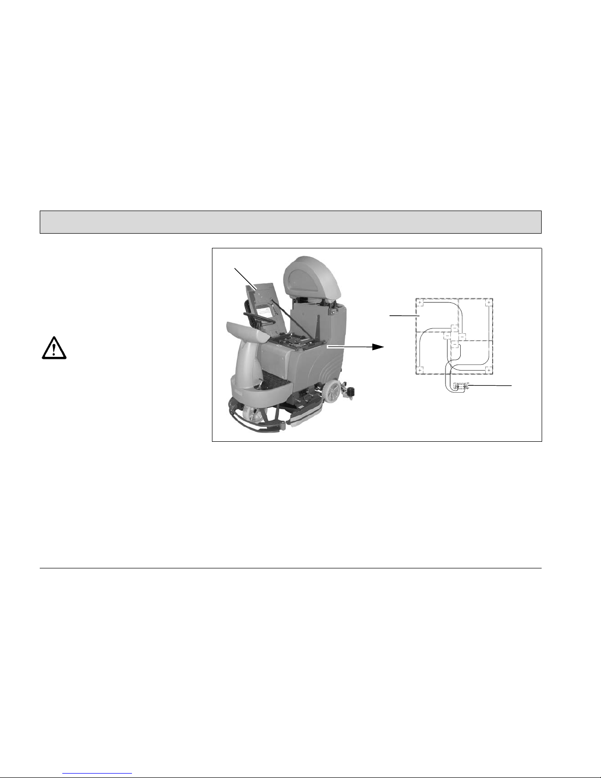
When a cleaning operation is activated,
cleaning agent is fed from the clean
water tank (Fig. 17/1) to the rotating
brushes on the brush head (Fig. 17/2).
As the vehicle is driving forwards, the
cleaning solution applied to the brushes
and floor is vacuumed up by means of
the squeegee (Fig. 17/3) and fed to the
waste water tank (Fig. 17/4).
Fig.17
3
2
4
1
35
Operation
3.2 Operating and indicator
elements
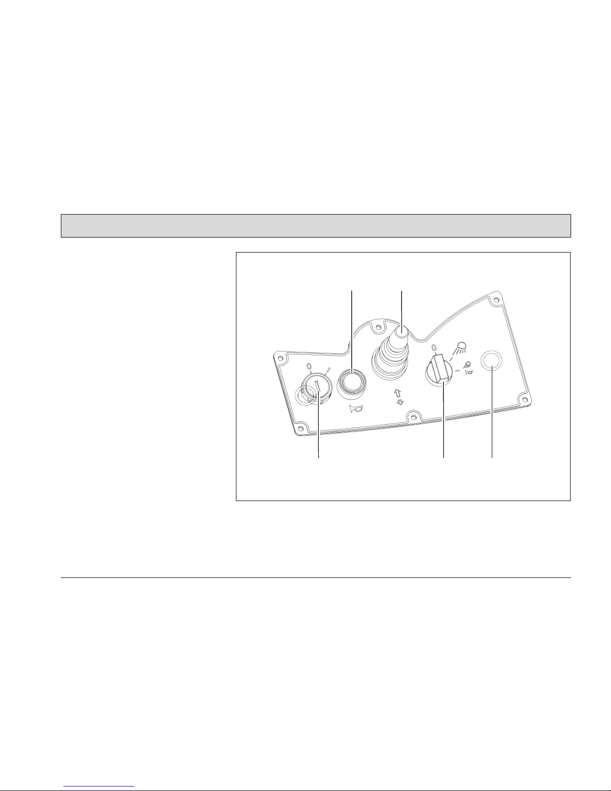
3.2.1 Left-hand operating panel
1 Key switch
2 Horn button
3 Driving direction selection switch
4 Switch for working lights or hazard
warning system (option)
5 Scrubbing-vacuum tool (option)
Fig.18
1
2 3
4 5

36
Operation
Key switch (Fig. 18/1)
It serves to switch the electrical system
on and off and to secure the vehicle
against unauthorized use. (When
switched on, the operating hour counter
also appears in the display.) When the
switch is set to OFF, all the switching
functions are returned to their original
state (reset).
Horn button (Fig. 18/2)
It serves to sound the horn
Driving direction selection switch
(Fig. 18/3)
It serves to select the driving direction:
• Control forward = forward drive
• Control lever O = neutral position
• Control lever back = reverse drive
To change the driving direction, stop
the vehicle by applying the service
brake, select the new direction and accelerate again.
Switch for working lights or hazard
warning system (option) (Fig. 18/4)
It serves to switch the buzzer and warning light on and off, as well as to switch
the working lights on and off. Function
is also possible without the key switch.
(Warning light / Working lights are options).
Scrubbing-vacuum tool (option)
(Fig. 18/5)
This serves to activate the manual floor
scrubbing and vacuuming tool. The
function is can only be activated when
the parking brake is applied, the accelerator is not pressed and the driver is
not seated in the driver's seat

37
Operation
3.2.2 Right-hand operating panel
1 Indicator field
2 Button, silence kit (option)
3 Button, chemical dosage (option)
4 Button, squeegee and suction
turbine
5 Button, brush drive
6 Button, brush pressure adjustment
7 Button, clean water dosing
8 Button, clean water supply
9 Button, boost function
10 Button, brush head and squeegee
(Hakomatic button)
Fig.19
1
2
4
3
5
6
7
8
9
10

38
Operation
Indicator field (Fig. 19/1)
The indicator field provides a central
function monitoring facility and indicates all operating states.
Button for silent kit (option)
(Fig. 19/2)
This button is used to switch the suction
turbine to Silent mode. The Silent mode
icon appears in the indicator field.
Button for chemical dosage (option)
(Fig. 19/3)
This button is used to switch on the
chemical dosage. The chemical dosage
icon appears in the indicator field.
Button for squeegee and suction
turbine (Fig. 19/4)
The button is used to lower/raise the
squeegee and switch the suction turbine on/off. After the suction turbine is
switched off:
• the squeegee is raised after a delay
• the suction turbine is shutdown after
a delay.
Button for brush drive (Fig. 19/5)
This button is used to switch the drive
and water supply on/off and simultaneously lower the brush head.
Button for brush pressure
adjustment (Fig. 19/6)
The button is used to increase the
brush pressure if this is necessary due
to the degree of soiling.
Button for clean water dosage
(Fig. 19/7)
This button is used to regulate the
quantity of clean water. In addition, the
quantity of water is adapted to the driving speed. The clean water quantity being supplied is displayed in the indicator
field by a six-section icon.
Button for clean water supply
(Fig. 19/8)
This button is used to switch the clean
water supply on and off.

39
Operation
Button for boost function
(Fig. 19/9)
The boost function only works in combination with the Hakomatic button. When
the boost function has been activated,
the icons for scrubbing (Fig. /11), suction turbine operation (Fig. /9), clean
water supply at level 6 (Fig. /2) and the
icon for brush pressure adjustment
(Fig. /12) flash on the indicator field.
After one minute, the machine automatically switches back to the operating
mode in which the machine was running before the boost function was activated. The boost function can be
stopped at any time by pressing any
button, whereby the newly selected
function will be activated. Conditions for
the boost function:
• charge status of the battery is ok,
• suction turbine has not been deactivated by the float switch,
• Hakomatic button is activated.
Button for brush head and squeegee
(Hakomatic button) (Fig. 19/10)
The Hakomatic button serves to switch
the brush drive and suction turbine
on/off with simultaneous lowering/raising of the brush head and squeegee, respectively. The water quantity last
selected is supplied.
40
Operation
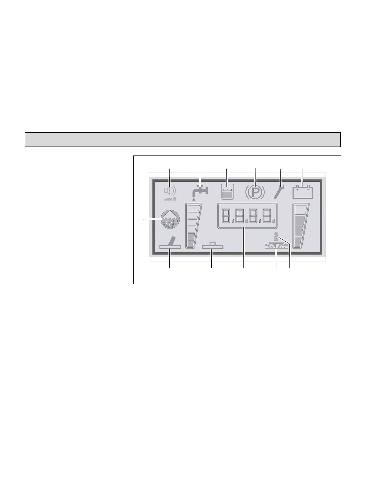
Indicator field
1 Icon, silent kit (option)
2 Icon, clean water dosage
3 Icon, waste water tank full
4 Icon, parking brake
5 Icon, service indicator
6 Icon, charge status indicator (TSG)
7 Icon, chemical dosage (option)
8 Icon, scrubbing-vacuum tool
(option)
9 Icon, suction turbine drive
10 Icon, operating hour counter
11 Icon, scrubbing
12 Icon, brush pressure adjustment
Fig.20
1 2 3
4
5
6
8
7
9
10
11 12

41
Operation
Icon, silent kit (option) (Fig. 20/1)
The icon appears when the option has
been activated. The right-hand, lower
bar goes out when the function is
switched on via the button.
Icon, clean water dosage (Fig. 20/2)
The icon appears when the clean water
supply button has been actuated and
the brush head is lowered.
Icon, waste water tank full (Fig. 20/3)
The icon appears when the waste water
tank is full. Emptying the waste water
tank, refer to Section 2.3.3.
Icon, parking brake (Fig. 20/4)
The icon appears when the driving direction selection switch is in its neutral
position and driving has been stopped.
Icon, service indicator (Fig. 20/5)
The service indicator lights up when an
error has occurred in the system and
the cleaning or driving process has
been interrupted. In addition to the service indicator, a four-digit service code
appears in the display of the operating
hour counter.
Please note down the service code and
notify the authorized Hako dealer responsible for you.
Icon, charge status indicator
(Fig. 20/6)
After switching the vehicle on, the
charge status indicator appears in the
display. The current battery charge status is indicated during operation. For
further information, refer to Section
2.3.7.
Icon, chemical dosage (option)
(Fig. 20/7)
The icon appears when the chemical
dosage (option) is switched on.
42
Operation
Icon, scrubbing-vacuum tool
(option) (Fig. 20/8)
The icon appears when the scrubbingvacuum tool button (A) has been
switched on. A floor scrubbing and vacuuming tool (option) can be deployed in
conjunction with the scrubbing-vacuum
function to apply and vacuum up cleaning liquids in areas difficult to access.
Icon, suction turbine drive (Fig. 20/9)
The icon appears when the suction turbine drive has been switched on. The
suction turbine continues to run for 15
seconds after the vacuuming function
has been switched off. The icon flashes
during this period.
Icon, operating hour counter
(Fig. 20/10)
After switching the machine on, the
software version and last service code
appear briefly in the operating hour
counter. The operating hour counter
then indicates the number of operating
hours currently accumulated.
Icon, scrubbing (Fig. 20/11)
The icon appears when scrubbing
mode has been switched on.
Icon, brush pressure adjustment
(Fig. 20/12)
The icon appears when brush pressure
adjustment has been switched on.
1.1.1.1

43
Operation
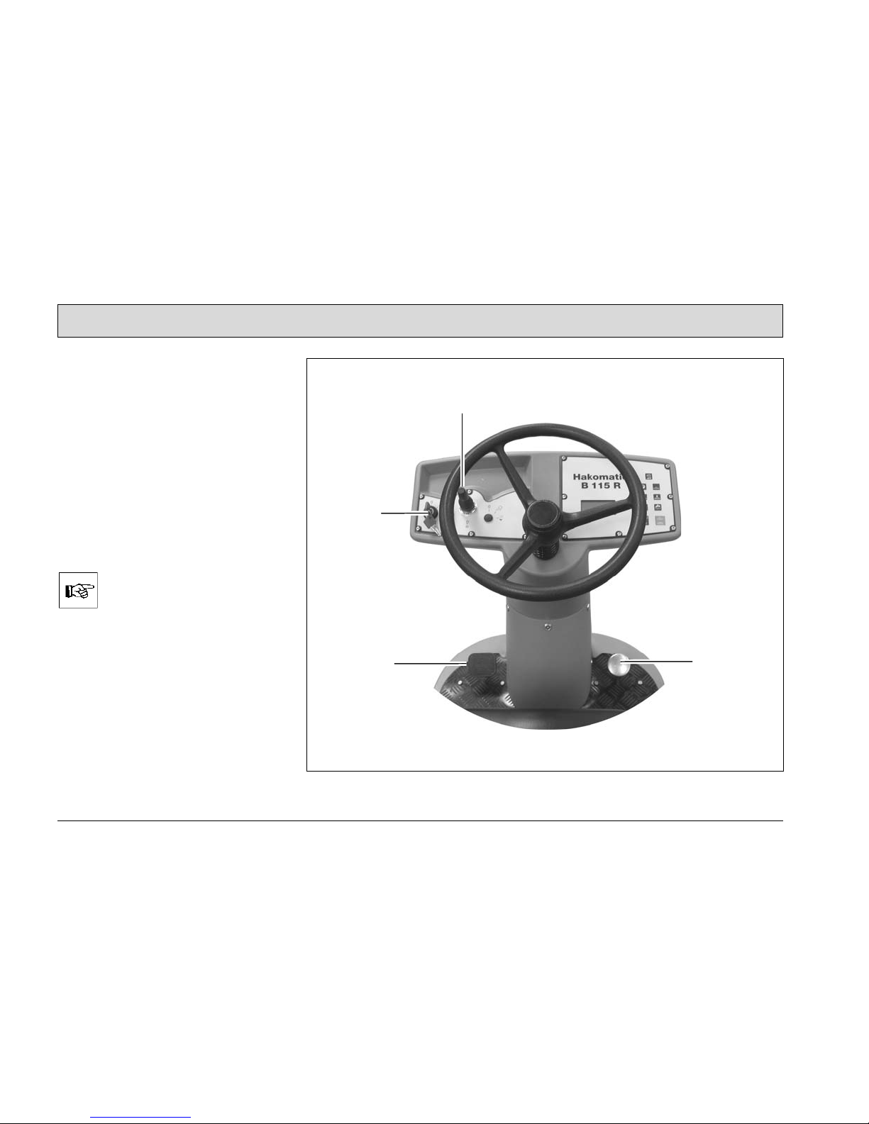
3.2.3 On the vehicle
1 Accelerator
2 Brake / Parking brake
3 Clean water tank filling neck
4 Water filter
5 Waste water draining hose
6 Clean water draining hose (with
water level indicator)
Fig.21
3
4
1
2
5
6

44
Operation
Accelerator pedal (Fig. 21/1)
When the vehicle has been switched
on, the accelerator is used to control the
driving speed in a continuously variable
adjustment. An operator must be seated on the driver's seat.
On releasing your foot from the accelerator, the vehicle decelerates and automatically returns to its neutral position.
Brake / Parking brake (Fig. 21/2)
The mechanical brake serves to slow
the vehicle down and park the vehicle.
Clean water filling neck (Fig. 21/3)
The clean water tank is filled through a
filling neck which can be opened.
Clean water filter (Fig. 21/4)
When the water is fed from the clean
water tank to the brush head, the water
is cleaned by a filter insert.
Waste water draining hose
(Fig. 21/5)
The waste water draining hose is used
to drain of the waste water which has
been vacuumed up.
Clean water draining hose (Fig. 21/6)
The draining hose is used to drain the
clean water tank.
45
Operation
Lever for cylindrical brush support
(Fig. 22/1)
This lever is used to lock/unlock the cylindrical brush support. The cylindrical
brushes can be disassembled quickly,
without the need for tools.
Dirt hopper, cylindrical brush head
(Fig. 22/2)
The cylindrical brush head is provided
with a dirt hopper equipped with a lock.
The dirt hopper can be removed to be
cleaned.
Ejector for disk brushes (Fig. 21/3)
The brush ejector enables the brushes
to be disassembled quickly, without the
need of any tools.
Power connection (Fig. 22/4)
The charger is supplied with power via
the power connection.
Fig.22
1
2
3
4

46
Technical Data
4 Technical Data
Unit TB 650 TB 750 TB 900 WZB 700 WZB 850
Dimensions
Vehicle length, with squeegee cm 166 166 166 166 166
Vehicle width, with squeegee cm 86.5 96 112 96 112
Vehicle height cm 144 144 144 144 144
Working width
Brush head cm 65 75 90 70 85
Squeegee cm 86.5 110 110 110 110
Weights
Weight (empty, without batteries) kg 345 345 347 345 347
Total weight (ready to operate) kg 720 720 727 720 727
Driving performance
Driving speed (forwards/reverse) kph 7.0/3.4 7.0/3.4 7.0/3.4 7.0/3.4 7.0/3.4
Climbing capacity % 10 10 10 10 10
Ramp angle (straight/inclined) Degrees 15°/5° 15°/5° 15°/5° 15°/5° 15°/5°
Turning circle cm 170 170 180 170 180
Wheels
Wheels (front/rear) Type EUTHAN 80 EUTHAN 80 EUTHAN 80 EUTHAN 80 EUTHAN 80
Wheel diameter mm 305 305 305 305 305
Drive (oil filling) Liters 0.5 0.5 0.5 0.5 0.5

47
Technical Data
Unit TB 650 TB 750 TB 900 WZB 700 WZB 850
Tank volume
Clean water tank tank Liters 116 116 116 116 116
Waste water tank Liters 116 116 116 116 116
Brush head
No. of brushes Pieces 2 2 2 2 2
Brush speed rpm 210 200 215 850 850
Suction
Air flow rate
m3/h
110 110 118 110 118
Vacuum mbar 170 170 170 170 170
Electrical installation
Nominal voltage V 24 24 24 24 24
Nominal power (max.) (P1) W 3260 3260 3260 3100 3100
Power consumption, drive motor (P1 / S2-120
min)
W 816 816 816 816 816
Power consumption, aspirating engine (P1) W 528 528 528 528 528
Power consumption, brush motor (P1) W 960 960 960 876 876
Power consumption, water pump (P1) W 100 100 100 100 100
Protection class III III III III III
Type of protection IPX3 IPX3 IPX3 IPX3 IPX3

48
Technical Data
Noise emission value
The sound power level (LwAd) measured according to EN 60335-2-72 under normal under working conditions is:
dB (A) 85
The sound pressure level (LpA) measured according to DIN EN 60335-2-72 (at
the driver's ear) under normal working conditions is:
dB (A) 66
Measurement inaccuracy (KpA): dB (A) 2
Vibration
The weighted effective value of acceleration, measured in accordance with DIN
EN ISO 5349, to which the upper parts of the body (hand-arm) are exposed under
normal working conditions:
m/s² < 2.5

49
Maintenance and Service
5 Maintenance and
Service
General information
It is essential to pay attention
to the information in Chapter
"Safety Information" before
completing any service or
maintenance work!
By adhering to the maintenance work
recommended by us, you can be sure
that the vehicle is always ready to be
put into operation.
Maintenance and repair work necessary on a daily and weekly basis can be
carried out by a driver trained to complete the work, all other Hako system
maintenance may only be completed by
personnel who are correspondingly
qualified and trained. Please contact
your nearest Hako service center or
authorized Hako dealer. Failure to observe this annuls any rights to claims
under the terms of guarantee in respect
of resulting damage or consequential
damage.
Always specify the serial number in the
case of inquiries and spare parts orders, refer to Section 1.7 - Rating plate.
5.1 Hako system maintenance
The Hako system maintenance:
• ensures that the Hako vehicle is always ready for operation (preventive
maintenance),
• minimizes operating costs, maintenance and repair costs,
• ensures the vehicle has a long service life.
Hako system maintenance provides individual modules explaining the special
technical work to be carried out and
prescribes the intervals at which the
work should be performed. Parts to be
replaced for the individual maintenance
tasks are defined and provided in spare
parts kits.
Hako system maintenance K:
Work to be carried out by the customer
according to the service and maintenance instructions in the operating
manual (daily and weekly). The driver/operator receives proper instruction
when the vehicle is delivered.
Hako system maintenance I:
(every 250 operating hours)
Completed by technical experts from an
authorized Hako service center in accordance with the specific vehicle system maintenance using spare parts kits.
Hako system maintenance II:
(every 500 operating hours)
Completed by technical experts from an
authorized Hako service center in accordance with the specific vehicle system maintenance using spare parts kits.
Hako system maintenance III/S:
(every 1000 operating hours, safety
check)
Completed by technical experts from
an authorized Hako service center in
accordance with the specific vehicle
system maintenance using spare parts
kits. Completion of all legally prescribed, safety-related tests in accordance with UVV, BGV, TÜV and VDE
requirements.

50
Maintenance and Service
5.2 Proof of Maintenance
Handover
Upgrading
Test drive
Handover to customer
Instruction
completed on:
at _________________ operating hours
Hako System Maintenance I
250 operating hours
Workshop Stamp
completed on:
at _________________ operating hours
Hako System Maintenance II
500 operating hours
Workshop Stamp
completed on:
at _________________ operating hours
Hako System Maintenance I
750 operating hours
Workshop Stamp
completed on:
at _________________ operating hours
Hako System Maintenance S
1000 operating hours
Workshop Stamp
completed on:
at _________________ operating hours
Hako System Maintenance I
1250 operating hours
Workshop Stamp
completed on:
at _________________ operating hours
Hako System Maintenance II
1500 operating hours
Workshop Stamp
completed on:
at _________________ operating hours
Hako System Maintenance I
1750 operating hours
Workshop Stamp
completed on:
at _________________ operating hours
Hako System Maintenance S
2000 operating hours
Workshop Stamp
completed on:
at _________________ operating hours
Hako System Maintenance I
2250 operating hours
Workshop Stamp
completed on:
at _________________ operating hours
Hako System Maintenance II
2500 operating hours
Workshop Stamp
completed on:
at _________________ operating hours
Hako System Maintenance I
2750 operating hours
Workshop Stamp
completed on:
at _________________ operating hours

51
Maintenance and Service
5.3 Maintenance Plan
Hako system maintenance,
customer
The following maintenance work must
be completed by the customer at the intervals stipulated.
Activity
Interval
Daily Weekly
Empty and clean the waste water tank o
Check the lid seal of the waste water tank; clean, if necessary o
Check the battery charge; recharge, if necessary o
Check the clean water filter; clean or change as necessary o
Fill the clean water tank and dose the chemicals o
Check the sealing strips on the squeegee; turn or change as necessary o
Check the deflector rubber of the side deflector, change as necessary o
Check the scrubbing quality of the brush head; clean the brushes, pad and pad
holder if necessary
o
Check the suction power of the squeegee; clean or change the sealing strips as
necessary
o
Check the suction hose between the squeegee and waste water tank is fitted
firmly and for signs of damage
o
Check the brushes and water retaining ring are fitted firmly and for signs of wear,
change as necessary
o
Test drive and function test o

52
Maintenance and Service
Hako system maintenance I
The following maintenance work must
be completed by an authorized Hako
service center.
Activity
Interval
Every 250 operating hours
Check the battery acid level and acid density; top up distilled water (PzS version), if
necessary
o
Check the charger (ventilation grid and air channel) o
Grease the steering pinion and gear rim o
Check the functionality of the brake and parking brake lock o
Check the brush head; change worn parts as necessary o
Check the clean water system; change worn parts as necessary o
Check the waste water and vacuum system; change worn parts as necessary o
Clean the brush motor ventilation grid of fluff and dirt o
Check the squeegee connection and rollers, adjust as necessary o
Check the front safety bar with deflection roller o
Check the wheel mounting bolts; retighten, if necessary (42 Nm) o
Check the electrical system; change worn parts as necessary o
Check the visual appearance of the vehicle (color, corrosion and labels) o
Test drive and function test o

53
Maintenance and Service
Hako system maintenance II
The following maintenance work must
be completed by an authorized Hako
service center.
Activity
Interval
Every 500 operating hours
All maintenance work in accordance with Hako system maintenance I o
Read out the error memory and evaluate the error messages o
Check the brake disk and brake blocks; change, if necessary o
Check the electric power (hydraulic motor, brush motor and suction turbine) o
Change the backup battery and set the real-time clock o
Check the visual appearance of the vehicle (color, corrosion and labels) o
Test drive and function test o

54
Maintenance and Service
Hako system maintenance III/S
(safety check)
The following maintenance work must
be completed by an authorized Hako
service center at least once a year.
Activity
Interval
Every 1000 operating hours
All maintenance work in accordance with Hako system maintenance II o
Clean carbon dust from the drive motor and check the carbon brushes move easily
and for signs of wear; change the carbon brushes, if necessary
o
Clean carbon dust from the brush motors and check the carbon brushes move easily
and for signs of wear; change the carbon brushes, if necessary
o
Test drive and function test o

55
Maintenance and Service
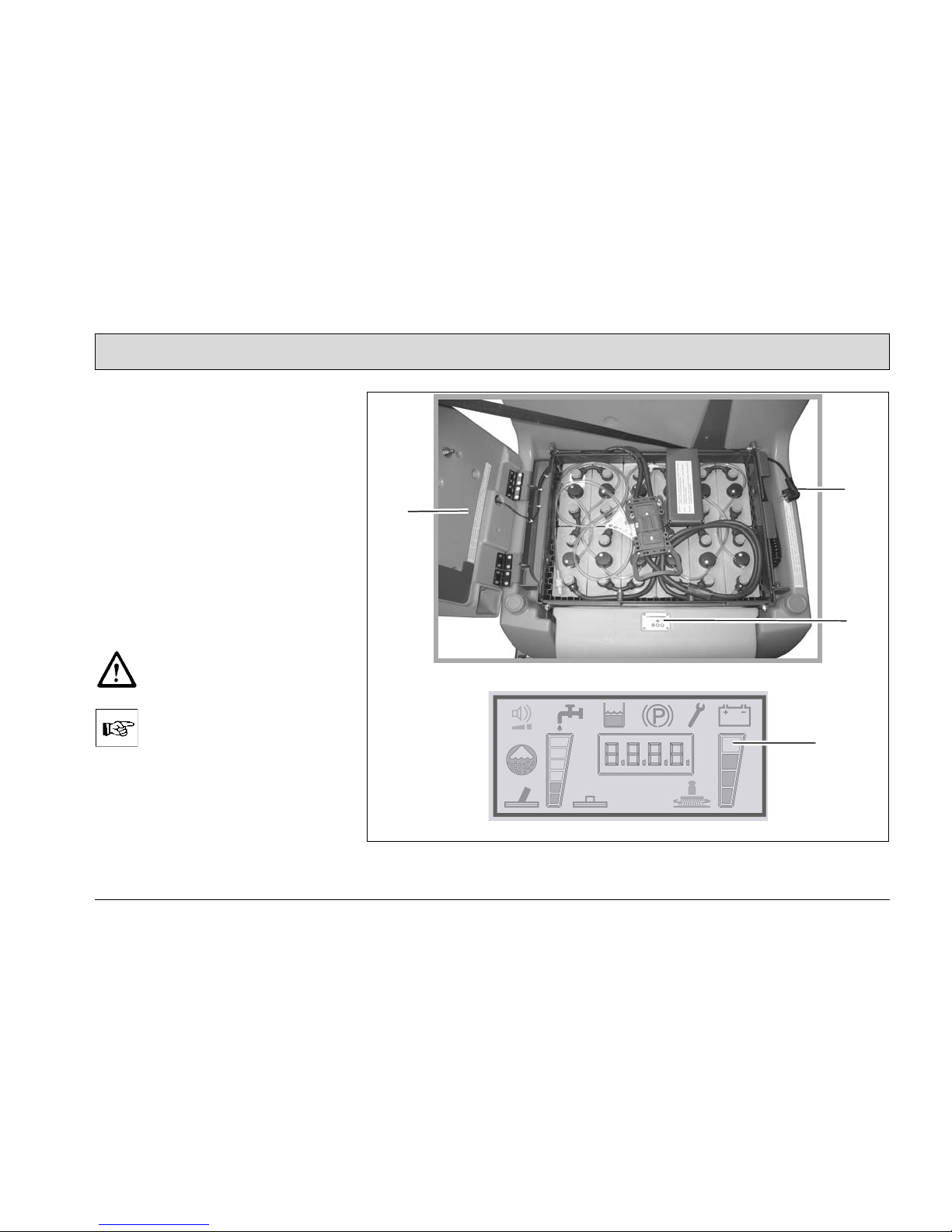
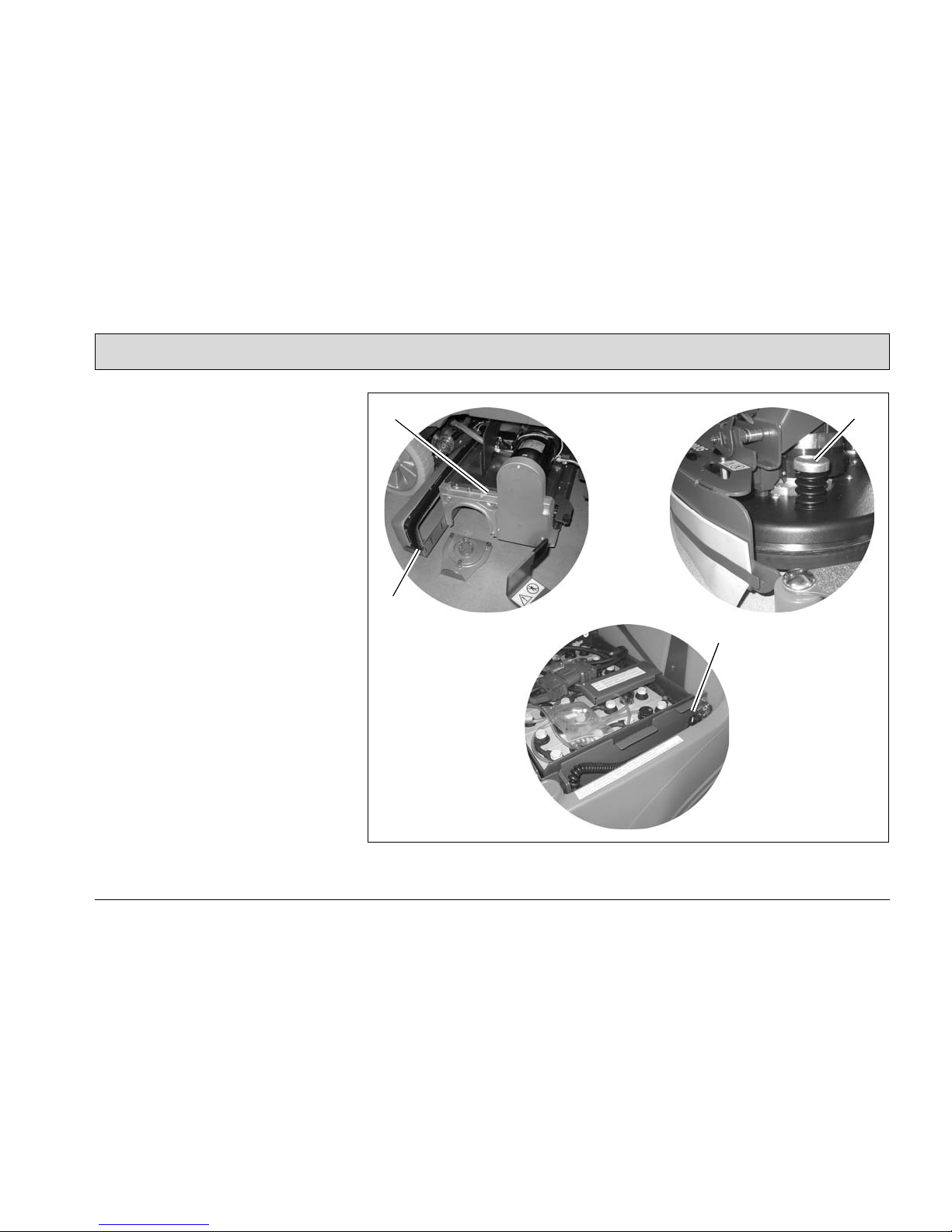
5.4 Battery system
1 Seat console
2 Battery plug
3 Water filling system
4 Charger
5 Charge status indicator
Handling and changing the
batteries, refer to Section 2.2.
Fig.23
1
2
3
4
5

56
Maintenance and Service
5.4.1 Water filling system
For upgrading the trough battery with a
water filling system (Fig. 23/3) , each individual cell is provided with a closure
plug with float indicator. Please read the
operating manual from the battery manufacturer for information on the fill level
indicator. If some cells are below the set
value, distilled water must be refilled in
them. In this case, the end piece of the
water filling system is connected to a
tank containing demineralized water (in
accordance with DIN 43530/4). Ensure
a sufficient gradient so that the water
can flow into the cells. When the fill level
required is reached, the plugs close the
cells automatically and indicate they are
full, the battery can be disconnected
from the water tank.
Refilling may only be completed when battery charging has
ended (green LED indicator on
the charger)
5.4.2 Charge status indicator (TSG)
The vehicle is equipped with a charge
status indicator (Fig. 23/4) to prevent
the batteries being fully discharged.
The total discharge signal transducer is
integrated in the electronics. If other
batteries are used, the total discharge
signal transducer must be adjusted.
The total discharge signal
transducer may only be adjusted by an authorized Hako service center.
5.4.3 Servicing the driving batteries
For information on servicing driving batteries, refer to operating manual 88-60-
2556.
5.4.4 Disposing of batteries
Used batteries with the recycling symbol contain reusable commodities. In
accordance with symbol with the
crossed out bin, these batteries must
not be disposed of in domestic waste.
Return and recycling must be agreed
on with an authorized Hako dealer in
accordance with § 6 and 8 BattV (Battery Directive)!

57
Maintenance and Service
5.5 Waste water and clean water
tank
1 Tank lid
2 Maintenance opening, clean water
tank
3 Filling neck, clean water tank
4 Draining hose, clean water tank
5 Draining hose, waste water tank
6 Filter sieve
7 Float switch, waste water tank
8 Cleaning opening, sieve
9 Fill level indicator, clean water tank
10 Clean water sieve with holding band
for the filling neck (option)
11 Clean water filter
12 Clean water tank
13 Waste water tank
Fig.24
1
2
4
5
6
7
8
9
2
12
10
11
13
2
3

58
Maintenance and Service
5.5.1 Cleaning the clean water tank
Park the vehicle so that the draining
hose (Fig. 24/4) is above a drain in the
floor. Remove the draining hose from
the holder and open the cap by turning
it counterclockwise.
Use the maintenance opening
(Fig. 24/ 2) to clean the clean water tank
(Fig. 24/12).
Clean the filter sieve (Fig. 24/6) by inserting a hose in the opening (Fig. 24/8)
and flushing the sieve back from the inside.
5.5.2 Cleaning the clean water filter
Check the clean water filter (Fig. 24/11)
weekly and clean or replace it as necessary.
1. Empty the clean water tank, refer to
Section 5.5.1.
2. Screw the filter cap off.
3. Remove the filter element in the filter
housing to clean it. Replace it with a
new one, if necessary.
4. Replace the filter element and filter
cap.
5.5.3 Cleaning the waste water tank
Clean the waste water tank (Fig. 24/13)
every day or as necessary.
1. Open the tank cap (Fig. 24/1) on the
waste water tank.
2. Remove the draining hose
(Fig. 24/5) from the holder and empty the waste water tank completely.
3. Flush out the remaining dirt with
clean water.
4. Also flush the draining hose.
The waste water tank must always be emptied and flushed
clean after finishing work. The
float switch (Fig. 24/7) must
also be rinsed clean. The cap
on the draining hose should be
cleaned regularly. Lubricate
the O-ring lightly, if necessary.
When disposing of the waste
water and the cleaning solution, observe all applicable legal regulations.
When working in the area of
the opened waste water tank
lid, it must be folded open fully
to prevent it being knocked
shut unintentionally.

59
Maintenance and Service
5.6 Disk brush head
1 Brush head
2 Brushes
3 Brush ejectors
Fig.25
1
3
2
2
3

60
Maintenance and Service
5.6.1 Cleaning the brushes
Clean the brushes (Fig. 25/2) on the
brush head (Fig. 25/1) daily or as necessary.
1. Raise the brush head.
2. Press the brush ejectors (Fig. 25/3)
downward and remove the brushes
to clean them.
5.6.2 Changing the brushes
Check the brushes on the brush head
weekly for signs of wear. In the case of
wear to a brush length of 1.5 cm, the
brushes must be changed.
1. Raise the brush head.
2. Press the brush ejectors (Fig. 25/3)
downward and remove the brushes.
3. Slide the new brush under the brush
head and press into the support using both hands.
61
Maintenance and Service
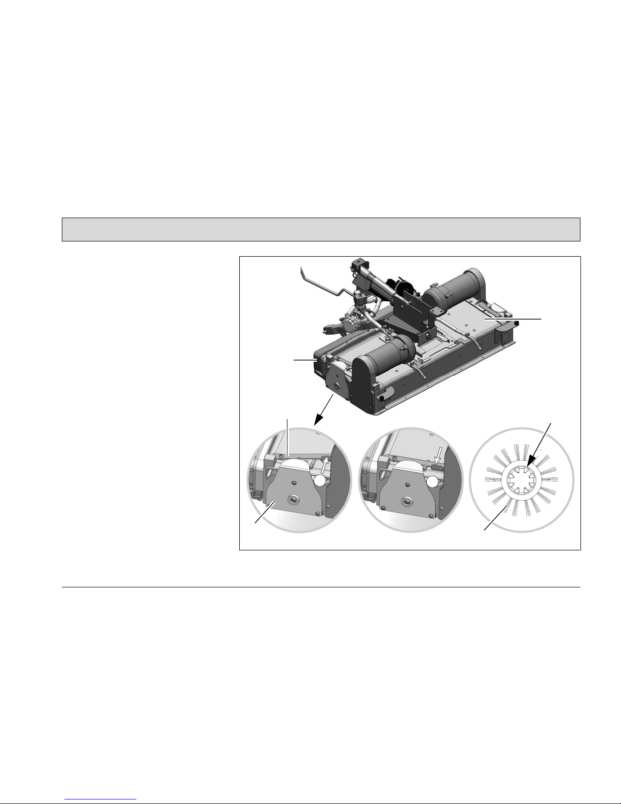
5.7 Cylindrical brush head
1 Cylindrical brush head
2 Locking lever
3 Brushes
4 Dirt hopper
5 Brush holder
Fig.26
2
3
5
X
A
B
4
1

62
Maintenance and Service
5.7.1 Emptying the dirt hopper
Remove and empty the dirt hopper
(Fig. 26/5) daily or as necessary.
5.7.2 Disassembling the brushes
Check the brushes (Fig. 26/3) on the
cylindrical brush head (Fig. 26/1) weekly for signs of wear and change as necessary.
1. Switch the vehicle off, remove the
key and apply the parking brake.
2. Pivot the deflector away, refer to
Section 5.8.
3. Unlock the brush holder (Fig. 26/5):
Press the locking lever (Fig. 26/2) to
position A and remove the brush
holder.
4. Pull out the brush (Fig. 26/3) and
check it.
5.7.3 Installing the brushes
1. Slide the brush in the cylindrical
brush head (toothing X must point
outwards) and allow to snap into
place on the oppositely facing catches.
2. Press the locking lever (Fig. 26/2) to
position A and mount the brush holder.
3. Locking the brush holder (Fig. 26/1):
Press the locking lever (Fig. 26/2) to
position B.
4. Pivot the deflector back, refer to Section 5.8.

63
Maintenance and Service
5.8 Deflector
1 Deflector
2 Wing nut
3 Clamping rail
4 Rubber deflector strips
5 Locking hooks
5.8.1 Pivoting the deflector away
1. Open the locking hooks (Fig. 27/1).
2. Pivot the deflector away to the side.
5.8.2 Changing the deflector rubber
Check the deflector rubber (Fig. 27/4)
daily or as required and change it when
necessary.
1. Loosen the wing nut (Fig. 27/2).
2. Slide the clamping rail (Fig. 27/3) to
the front until the hooks on the inner
side are free and the clamping rail
can be moved away.
3. Change the deflector rubber
(Fig. 27/4).
4. Reassemble in the reverse sequence.
Fig.27
1
2
3
5
4

64
Maintenance and Service
5.9 Squeegee
1 Squeegee
2 Star-shaped knob
3 Screw for angle adjustment
4 Suction hose
5 Fastening device
6 Washers for height adjustment
Fig.28
2
1
2
5
4
6
6
3

65
Maintenance and Service
5.9.1 Cleaning the squeegee
Check the squeegee (Fig. 28/1) daily
and clean as necessary.
To clean the squeegee, raise it, disconnect the suction hose (Fig. 28/4), loosen the two star-shaped knobs
(Fig. 28/2) and remove the squeegee.
5.9.2 Changing the sealing strips
Check the inner and outer sealing strips
on the squeegee (Fig. 28/1) weekly for
signs of wear. The sealing strips can be
turned four times (90°) and reused.
1. Raise the squeegee.
2. Pull off the suction hose, loosen the
two star-shaped knobs and remove
the squeegee.
3. Loosen the fastening device
(Fig. 28/5) and remove the outer
sealing strip. Turn the sealing strip or
replace it, as necessary. Change the
inner sealing strip in the same way.

66
Maintenance and Service
5.9.3 Adjusting the sealing strips
Angle adjustment
The angle adjustment is the decisive
factor in ensuring the squeegee's sealing strips lie evenly on the floor.
1. Park the machine on a level surface
and lower the squeegee.
2. Loosen the counternut on the screw
(Fig. 28/3) and use the counternut to
adjust the squeegee so that the ends
of the sealing strips just make contact with the floor.
Fig. A
Turn the counternut counterclockwise: Distance from sealing strip to
floor is reduced in the middle.
Fig. B
Turn the counternut clockwise: Distance from sealing strip to floor is increased in the middle.
3. Switch the vehicle on and check the
suction pattern. While driving, the
sealing strips must make an overall,
even contact with the floor (in the
center and at both ends).
4. Tighten the counternut of the adjusting bolt at 7 Nm.
Fig.29
B
A

67
Maintenance and Service
Height adjustment
The height adjustment is set to 3 mm at
the factory. If, despite an optimum angle adjustment, streaks are produced,
the distance between the rollers and
floor must be adjusted by altering the
number of washers (Fig. 28/6) on the
holder.
In the case of very smooth floors, e.g.
laminated screed, PVC, linoleum, etc.:
Number of washers = 2. This corresponds to a clearance of approx. 2 mm
to the floor.
In the case of very uneven floors, e.g.
poorly laid tiles (puddles form):
Number of washers = 4. This corresponds to a clearance of approx. 4 mm.
3 mm
2 mm
4 mm

68
Maintenance and Service

69
Hako-Werke GmbH
Hamburger Straße 209-239
D-23843 Bad Oldesloe
declares in sole responsibility
that the product
Hakomatic B115R
Type: 7090
to which this declaration relates, conforms with the relevant provisions of the
safety and health requirements stipulated in EU Directive 2006/42/EC and is in
accordance with
2004/108/EEC.
Reference was made to the following
standards and/or norms and/or technical specifications to ensure proper implementation of the safety and health
requirements in the EU Directives:
EN 60335-2-72
EN 61000-6-2
EN 61000-6-3
Bad Oldesloe, 26.09.2011
Dr. Rainer Bavendiek
Director R&D
Name of the authorized person who
compiles the technical documents for
Hako:
Ludger Lüttel
EC Declaration of Conformity
(in accordance with EC Directive 2006/42/EC)

Advanced Technology for a
Cleaner, Better Environment
Advanced Technology for a Cleaner, Better Environment
Hako-Werke GmbH · Stammwerk und Hauptverwaltung
Hamburger Str. 209-239 · D-23843 Bad Oldesloe
·
(04531) 806-0 · Fax (04531) 806-338
88-10-2950
 Loading...