

Page 1
®
SMD HOT TWEEZER
Instruction Manual
Thank you for purchasing the HAKKO 950 SMD Hot Tweezer.
Please read this manual before operating the HAKKO 950.
Store the manual in a safe, easily accessible place for future reference.
CAUTION
The HAKKO 950 cannot function by itself. It must
•
be connected to a HAKKO station. Specific
information can be found in the instruction manual
for your particular HAKKO station.
Before operating the HAKKO 950 for the first
•
time,be sure to calibrate the station.
Do not set the tip temperature to over 400 C/752 F.
•
Table of Contents
Packing List/Applicable Models/
Specifications
Precautions
Names of Parts
Setting up the HAKKO 950
Replacing the Tip/Tip selection
Operating Instructions
Troubleshooting Guide
Checking for breakage of the heating element,
cord assembly and tip to ground resistance
Maintenance/Tip Care and Use
Parts List
Tweezer/Iron Holder/Tips
Wiring Diagram
…………………………………………1
……………………………………………2
………………………………………3
………………………3,4
……………………5
………………………………6
………………………………7
……………………10
……………………………………11,12,13
………………………………………14
…8,9
Page 2
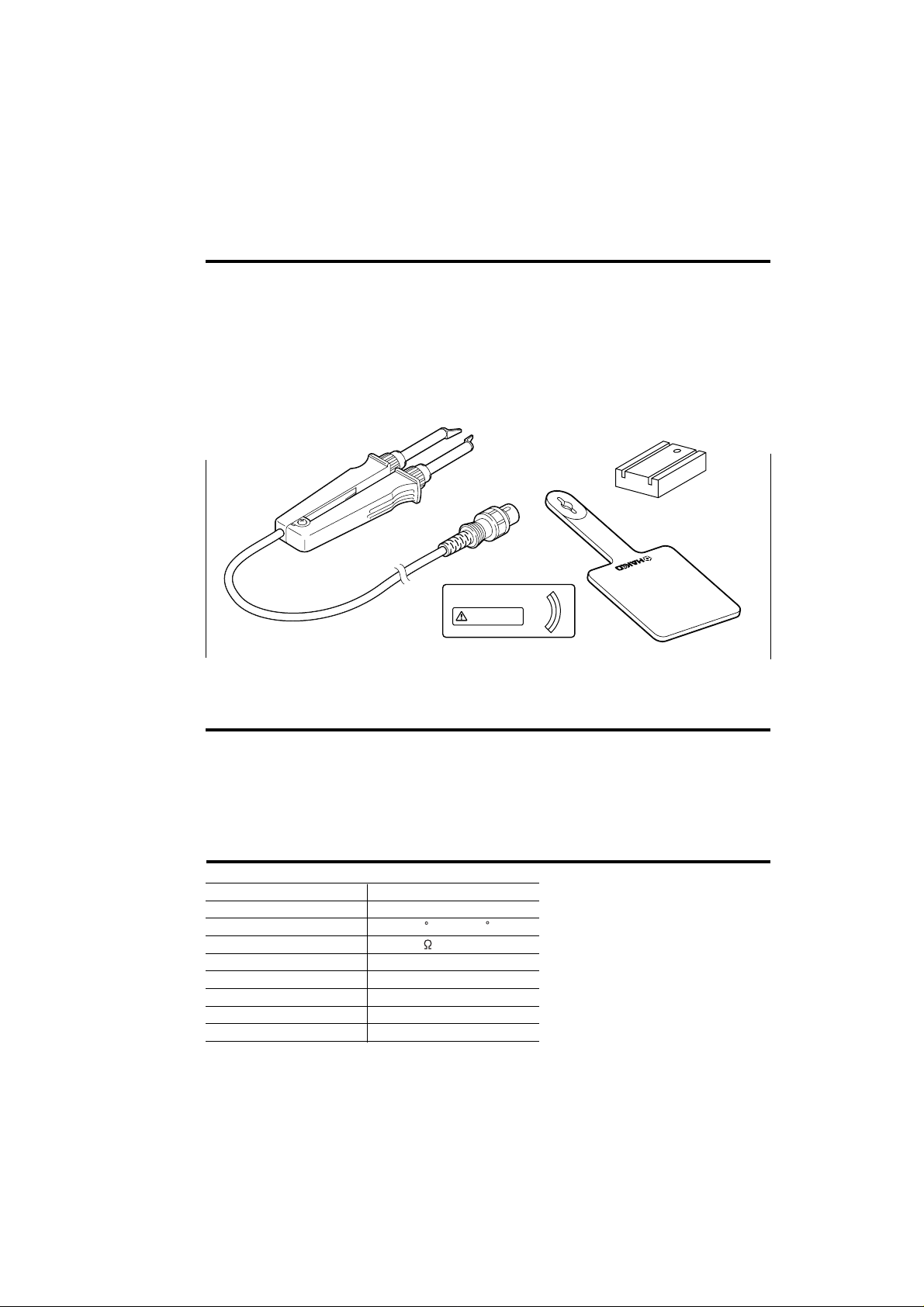
Packing List
Please check the contents of the HAKKO 950 package and confirm that all the items listed
below are included.
Tweezer
Caution Sticker
Heat Resistance Pad
Tip Alignment Tool
Instruction Manual
Tweezer
……………………………………… 1
………………………………1
…………………………1
…………………………1
…………………………1
Tip Alignment Tool
Do not operate this station
over 400 C with HAKKO 950.
Caution Sticker
Heat Resistance Pad
Applicable Models
In order to function, the HAKKO 950 must be connected to one of the
following HAKKO stations: HAKKO 700, 701, 702, 926, 927, 928,
936, 937, 939.
Specifications
Name HAKKO 950
Power Consumption
*Specifications and design subject to change without notice.
1
50W
200-400 C/392-752 FTemperature Range
Under 2Tip to Ground Resistance
Under 2mV (TYP.0.6mV)Tip to Ground Potential
Ceramic HeaterHeating Element
1.2m (4 ft.)Cord Assembly
186mm (7.3 in.)Total Length (w/o Cord)
93g (0.2 lbs.)Weight (w/o Cord)
Page 3
Precautions
In this instruction manual, “warning” and “caution” are defined as follows.
WARNING
WARNING: Misuse may potentially cause death of, or serious injury to, the user.
CAUTION : Misuse may potentially cause injury to the user or physical damage
to the objects involved.
For your own safety, be sure to comply with these precautions.
CAUTION
When the power is on, the tip temperature is between 200 C/392
F and 400 C/752 F. Since mishandling may lead to burns or fire,
be sure to comply with the following precautions.
Do not touch the metallic parts near the Tip.
•
Do not use the product near flammable items.
•
Advise other people in the work area that the unit can reach a very high temperature and
•
should be considered potentially dangerous.
Turn off the power while taking breaks and when finished using the unit.
•
Before replacing parts or storing the unit, turn off the power and allow the unit to cool to
•
room temperature.
To prevent damage to the unit and ensure a safe working
environment, be sure to comply with the following precautions.
Do not use the unit for applications other than those specifically described in the
•
instruction manual.
Before using the HAKKO 950 for the first time, calibrate the tip temperature.
•
Do not set the tip temperature to over 400 C/752 F.
•
Do not rap the HAKKO 950 against the work bench to shake off residual solder, or
•
otherwise subject the iron to severe shocks.
Do not modify the unit.
•
Use only genuine HAKKO replacement parts.
•
Do not wet the unit or use the unit when your hands are wet.
•
The operating process will produce smoke. Make sure the area is well ventilated.
•
Pull on the plug to disconnect the HAKKO 950 from the station outlet. Do not pull the
•
cord.
While using the unit, don’t do anything which may cause bodily harm or physical damage.
•
2
Page 4
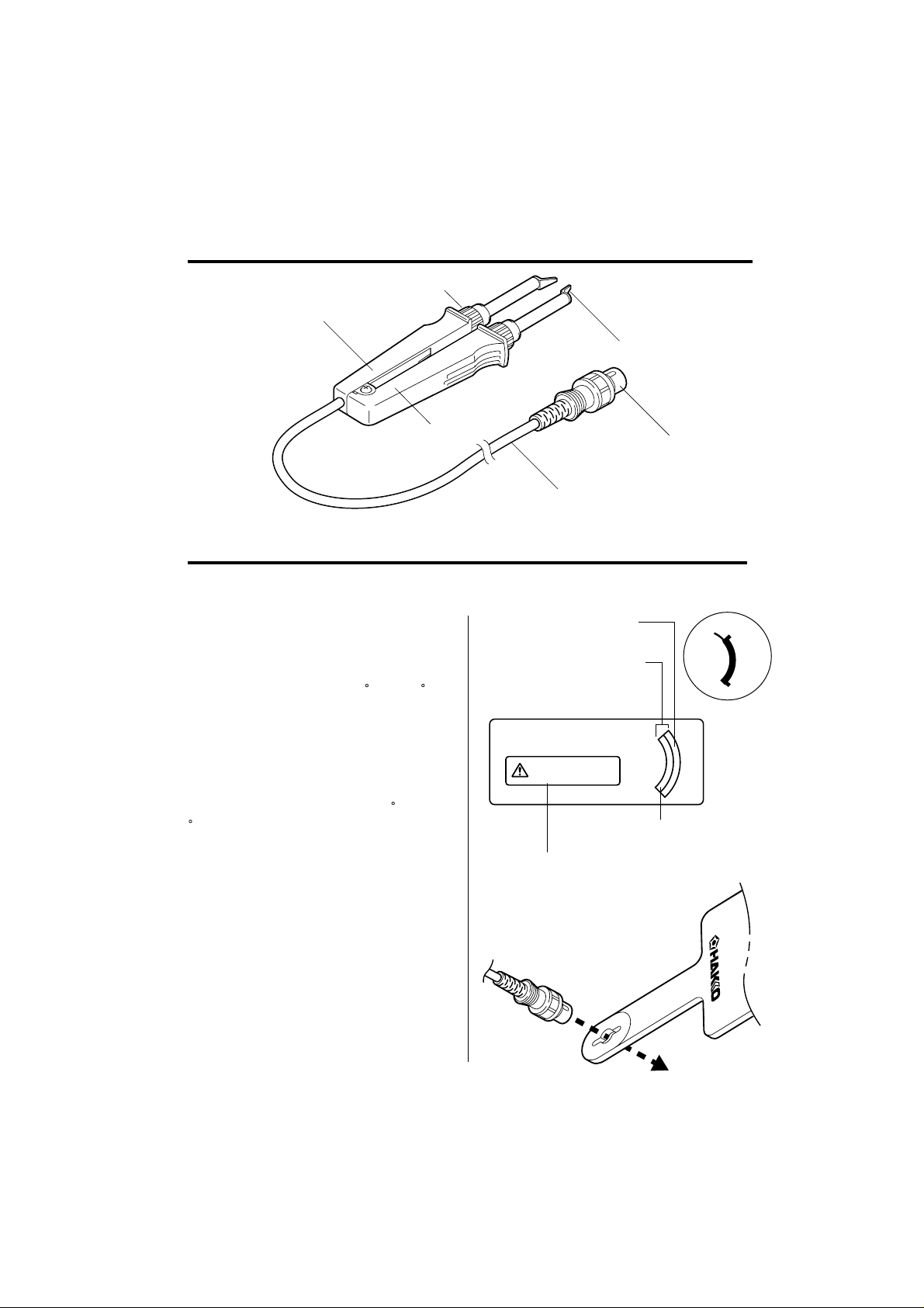
Names of Parts
Nipple
Handle B
Tip
Handle A
Cord Assembly
Setting up the HAKKO 950
1. Affix the caution
sticker to the station.
The HAKKO 950 cannot be used at
temperatures above 400 C (752 F).
Higher temperatures may damage
the station. Be sure to affix the caution sticker to the station.
When using the HAKKO 950 SMD
Hot Tweezer, do not operate this sta-
tion at temperatures over 400 C (752
F).
For HAKKO 700,702
Dial type sticker only
Place the sticker above
the temperature
indicator lines.
Do not operate this station
over 400¡C with HAKKO 950.
Put the sticker in a visible area
such as the front or top panel
of the station.
Plug
400
450
480
For HAKKO 926,936
928,701
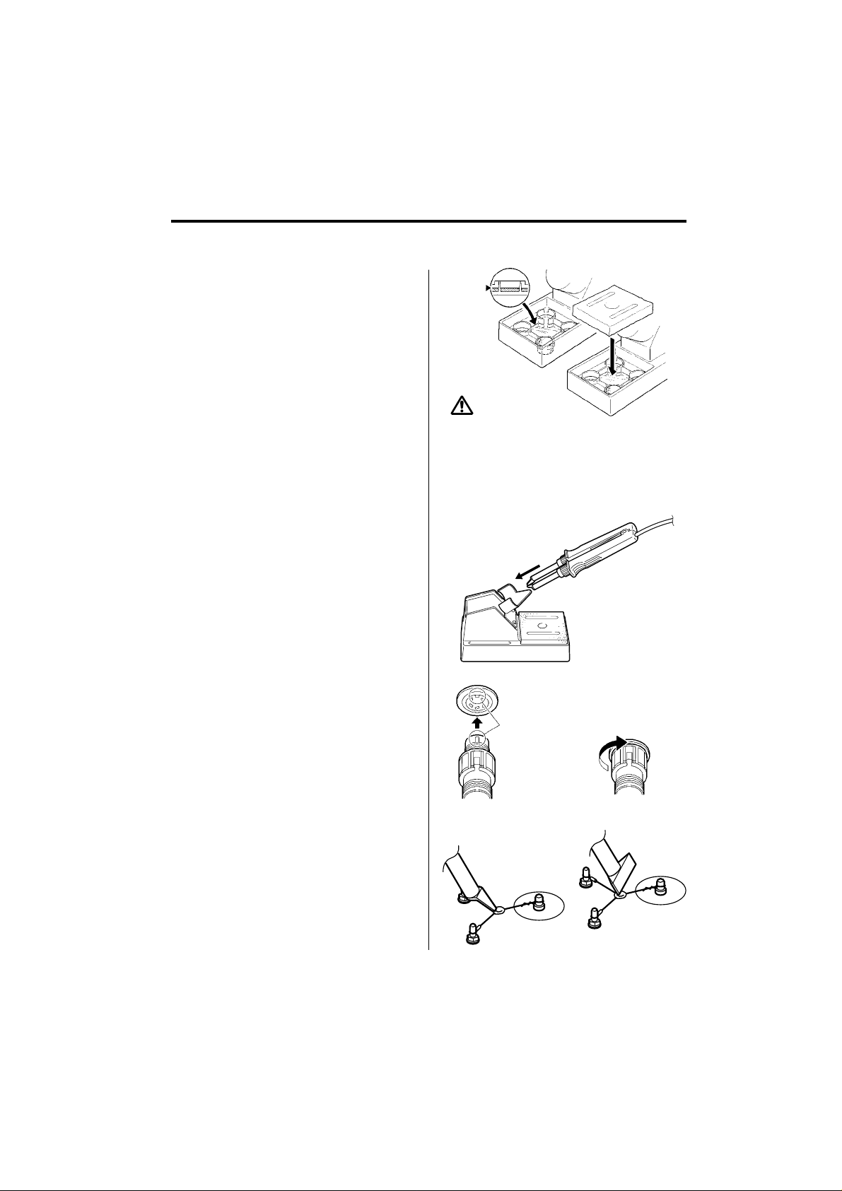
2. Install the Heat
Resistance Pad
Insert the cord plug through the hole
in the Heat Pad. The Heat Pad is
used when the soldering tip is
replaced.
3
Page 5
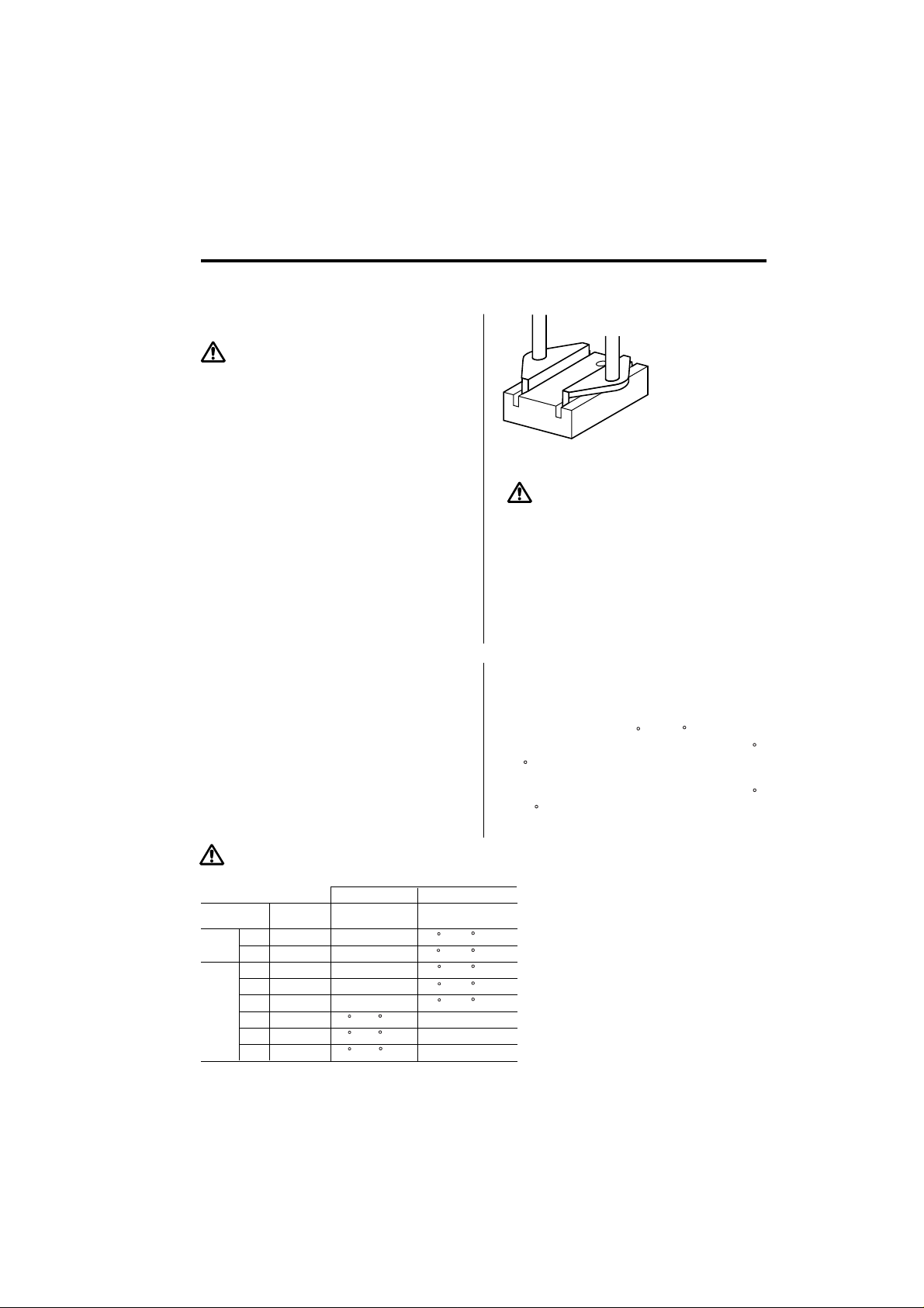
3. Iron holder
(Optional, part no. C1313)
An optional iron holder (part no.
C1313) is available for use with the
HAKKO 950.
Dampen the small cleaning sponge
1.
with water and squeeze it dry.
Place it in one of the 4 openings in
the iron holder base.
Add water to approximately the
2.
level shown in illustration. The
small sponge will absorb water to
keep the larger sponge above it
wet at all times.
Note: The large sponge may be
used separately (without the small
sponge and water)
3.
Dampen the large cleaning sponge
and place it on the iron holder
base.
4. Connections
Connect the Plug to the receptacle.
1.
Place the HAKKO 950 in the iron
2.
holder.
Plug the power cord into the power
3.
supply. Be sure to ground the unit.
CAUTION
The sponge is compressed. It will swell when
moistened with water. Before using the unit,
dampen the sponge with water and squeeze it
dry.
Always use a damp sponge to clean the tip.
Never wipe the tip clean on a dry sponge as
this can damage the tip.
@Receptacle
Align the grooves and pins,
and push straight in.
5. Calibration
Before operating the HAKKO 950, be
sure to calibrate the station using a
tip thermometer (HAKKO 191 Thermometer or 192 Soldering Tester.
When calibrating the tip for removing
SOP´s, place the edge of the tip on
the measuring point of the HAKKO
191 or 192, See sketch.).
Please refer to the instruction manual
for your station.
Turn clockwise firmly.
Tip/SOP
Tip/CHIP
4
Page 6
Replacing the Tip/Tip selection
Replacing the Tip
CAUTION
Be sure to turn off the power switch before
replacing the tip.
Loosen the nipple by turning it
1.
counterclockwise. It is not necessary to pull it out completely.
When the tip is heated, grasp the
2.
pipe part using the heat resistance
pad of the tip and pull.
Insert the new tip as far as it will
3.
go, and align it so that it is parallel
to the other tip.
Tighten nipple to fix the tip in
4.
place.
Tip Selection (Refer to P13)
The tip temperature will vary according to the shape of the tip. The preferred method of adjustment uses a tip
thermometer. (See your station's
instruction manual.) Less accurate
methods include adjusting the temperature control knob and calibrating
with a room thermometer.
CAUTION
Use only genuine HAKKO 950 replacement tips.
5
CHIP
SOP
Part No.
A13791L
A13782L
A13808L
A138110L
A138213L
A138318L
A138420L
A138525L
Dial Type Station
Difference From
CHIP 2L
0
0
0
0
-5 C (-9 F)
-5 C (-9 F)
-5 C (-9 F)
Digital Type Station
Compensation
Value
+4 C (+7 F)
+4 C (+7 F)
+4 C (+7 F)
+4 C (+7 F)
+4 C (+7 F)
0
0
0
SOP tip only
Use the tip alignment tool to
easily align the two tips in parallel.
CAUTION
The tip is very hot. If handled improperly,
it can cause serious burns.
Do not hold onto the heat resistance pad for
a long period.
1. Dial type station
Example: When using an SOP 25L tip at
a temperature of 400 C (750 F), the difference between this tip and CHIP 2L is -5 C
(-9 F).
Set the temperature control knob to 405 C
(759 F).
2. Digital type station
Digital type stations can be calibrated with a room thermometer. Refer
to the compensation value chart
below.
Specific instructions can be found in
your station's instruction manual.
Page 7

Operating Instructions
1. Set the Temperature
CAUTION
Never set the temperature to any value over
400˚C (752˚F). Doing so may damage the
station.
Set the temperature according to the
type of work to be done.
2. Apply solder or flux.
If there is insufficient solder on the
PWB, or the soldered area is too
small, apply solder or flux to the
PWB. Solder may also be applied to
the tip.
3. Melt the solder
Place the tip on the soldered part and
melt the solder. Confirm that the
solder is fully melted. See sketch `A´.
4.
Remove the componen
After confirming that the solder is fully
melted, lightly squeeze the tweezer to
grasp the component and lift to
remove the component. See sketch
`B´.
t
CAUTION
Very high tip temperatures may damage the
printed circuit board, possibly causing the
printed pattern to become detached. HAKKO
recommends setting the tip temperature to
300˚C (572˚F) for all normal work, and raising it
only when a specific job requires a higher
temperature. Using the lowest possible
effective temperature not only helps protect
parts that are sensitive to heat, it also helps
protect the tip from deterioration caused by
heat.
A
CAUTION
(For users of the HAKKO 937 Soldering Station)
The HAKKO 950 contains a sensor—attached to the heating element in
handle B—to detect the tip temperature. The HAKKO 937 Soldering Station’s heater error function will not
operate if the heating element in handle A is broken.
B
6
Page 8

Troubleshooting Guide
English
More information can be found in your station’s instruction manual.
Problem 1.
WARNING
The tip does not heat up.
Problem 2.
The tip heats up intermittently.
Problem 3.
The tip is not wet.
Disconnect the power plug before servicing.
Failure to do so may result in electric shock.
Check 1. Is the cord assembly
broken ?
• Refer to ‘Checking for breakage in the
cord assembly.’
Check 2. Is the Heating Element
broken?
• Refer to ‘Checking for breakage in the
heating element.’
Check 1
Check 3. Is the tip temperature too
high?
• Set an appropriate temperature.
Check 4. Is the tip clean?
• Refer to ‘Tip Care and Use’
Problem 4.
The tip temperature is too low.
Problem 5.
The tip can not be pulled off.
Problem 6.
The tip doesn't hold the
desired temperature.
7
Check 5.
• Refer to ‘Inspect and clean the tip’
Check 6. Is the iron calibrated
correctly?
• Recalibrate.
Check 7. Is the tip seized?
Is the tip swollen because
of deterioration?
•
Replace the tip and the heating element.
Check 6 above.
Is the tip coated with oxide?
Page 9

Checking for breakage of the heating element,
cord assembly, and tip to ground resistance
Disconnect the plug and measure the
resistance between the connecting
plug pins as follows.
If the values of 'a' and 'b' are outside
the ranges shown in the chart,
replace the heating element (sensor)
and/or cord assembly.
1.
Broken heating element
CAUTION
Be sure to measure the resistance of the heating element in both handles A and B. If one of
the heating elements is found to be broken,
replace both heating elements.
Disassembling the HAKKO 950
(Refer to P11,12)
1. Loosen the nipple by turning it
counterclockwise.
2. Pull out the tip.
3. Remove the screw.
4. Remove the strut pin, and
detach handles A and B.
CAUTION
Do not lose the tension spring.
5. Remove the self-tapping screw
and the handle cover.
6. Pull out the PWB and the heating
element.
a Between pins 4&5
(Heating Element)
b Between pins 1&2
(Sensor)
c Between pin 3&Tip
3
4
5
1
Heating Element (Red)
Sensor (Blue)
2.5 - 4.5 (Normal)
43 - 58
Under 2
2
S
(Normal)
H1
H2
H2
S
H1
Measure when the heating element is
at room temperature.
1.Resistance value of heating element (RED) 2.5 - 4.5
2.Resistance value of sensor (BLUE)
43-58 @If the resistance value is not
normal, replace the heating element.
(Refer to the instructions included
with the replacement part.)
8
Page 10

2. Broken Cord
There are two methods of testing the
cord.
CAUTION
The LED heater lamp will flicker even with a
normal cord if the temperature reaches 400˚C
(752˚F).
3. Checking the tip to
ground resistance
1.
Turn the unit ON and set the temperature to 400˚C(752˚F). Then
wiggle and kink the iron cord at
various locations along its length,
including the strain relief area.
If the LED heater lamp flickers,
then the cord needs to be
replaced.
2.
Check the resistance between the
pin of the plug and the wire on the
terminal in the handle B.
Pin 1: Red
Pin 2: Blue
Pin 3: Green
Pin 4: White
Pin 5: Black
The value should be 0 . If it is
greater than 0 or is , the cord
should be replaced.
If the value of ‘c’ (between pin 3 & tip)
is over the above value 2 as
measured with a tester, remove the
oxidization film by lightly rubbing with
sand-paper or steel wool the points
shown below.
9
Page 11

Maintenance
Inspect and Clean the Tip
CAUTION
Never file the Tip to remove oxide.
Tip Care and Use
1.
Set the temperature to 250 C (482
F).
2.
When the temperature stabilizes,
clean the tip with the cleaning
sponge and check the condition of
the tip.
3.
If there is black oxide on the solderplated portion of the tip, apply new
solder (containing flux) and wipe
the tip on the cleaning sponge.
Repeat until the oxide is completely
removed. Coat with new solder.
4.
If the tip is deformed or heavily
eroded, replace it with a new one.
•Tip T emperature
•Cleaning
•When Not in Use
•After Use
High operating temperatures can degrade
the tip. Use the lowest possible operating
temperature.
Clean the tip regularly with a cleaning
sponge, as oxides and carbides from the
solder and flux can form impurities on the
tip. These impurities can result in defective joints or reduce the tip's heat conductivity.
Never leave the HAKKO 950 sitting at
high temperature for long periods of time,
as the tip's solder plating will become covered with oxide, which can greatly reduce
the tip's heat conductivity.
Wipe the tip clean and coat the tip with
fresh solder. This helps prevent tip oxidation.
10
Page 12

Parts List (Tweezer/Iron Holder)
Note: Spare or repair parts do not include mounting
screws, if they are not listed on the description.
Screws must be ordered separately.
14
13
13
15
16
16
8
Tapping Screw
M 3 x 8 (2)
5
9
6
Pan Head Screw
M 3 x 14 (1)
Spring Washer
M 3 (1)
3
10
4
Item No. Part No. Part Name Description
1 Tip See P.13
2 A1377 Heating Element 24V-50W (25W x 2)
3 B2289 Nipple
4 B2290 Terminal
5 B2295 Tension Spring
6 B2292 Handle A
7 B2294 Handle B
8 B2291 Handle Cover A
9 B2293 Handle Cover B
10 B2296 Strut Pin
11 B2297 Cord Asse'y
12 B2032 Grounding Spring
13 C1313 Iron Holder With Cleaning Sponge
14 A1386 Cleaning Sponge
15 B2300 Heat Resistance Pad
16 B2301 Tip Alignment Tool
11
11
2
1
1
5
2
12
4
Hexagon Nut
M 3 (1)
7
11
3
1
12
Page 13

Parts List (Tips)
Part No.
A1379
CHIP
A1378 Tip/CHIP 2L
SOP
A1380 Tip/SOP 8L
A1381 Tip/SOP 10L
A1382 Tip/SOP 13L
A1383 Tip/SOP 18L
A1384 Tip/SOP 20L
A1385 Tip/SOP 25L
Part Name
Tip/CHIP 1L
Size A Shape
1mm (0.04 in.)
2mm (0.08 in.)
A
8mm (0.31 in.)
10mm (0.39 in.)
13mm (0.51 in.)
18mm (0.71 in.)
20mm (0.79 in.)
25mm (0.98 in.)
A
13
Page 14
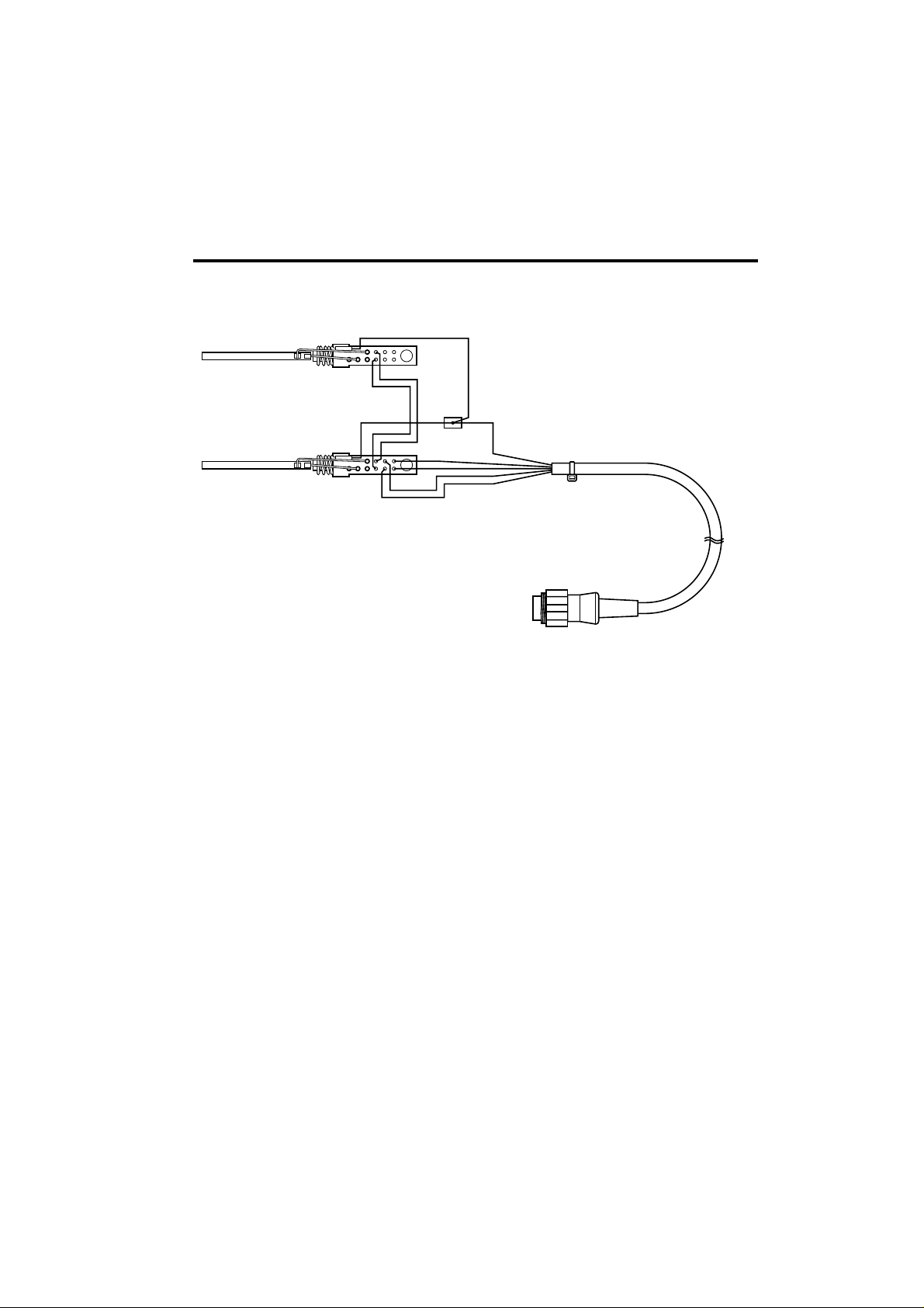
Wiring Diagram
14
Page 15

®
HEAD OFFICE
4-5, SHIOKUSA 2-CHOME, NANIWA-KU, OSAKA, 556 JAPAN
TEL: (06) 561-3225 FAX: (06) 561-8466
TLX: HAKKOOSA J65274
OVERSEAS AFFILIATES
U.S.A.: AMERICAN HAKKO PRODUCTS, INC.
25072 ANZA DR. SANTA CLARITA, CA 91355, U.S.A.
TEL: (805) 294-0090 FAX: (805) 294-0096
Toll Free (800)88-HAKKO
4 2 5 5 6
S'PORE: HAKKO PRODUCTS PTE., LTD.
1, GENTING LINK #02-04, PERFECT INDUSTRIAL
BUILDING, SINGAPORE 349518
TEL: 7482277 FAX: 7440033
HONG KONG: HAKKO DEVELOPMENT CO., LTD.
ROOM 804 EASTERN HARBOUR CENTRE,
28 HOI CHAK STREET, QUARRY BAY, HONG KONG.
TEL: 2811-5588 FAX: 2590-0217
PHILIPPINES: HAKKO PHILS TRADING CO., INC.
NO. 415 WINDSOR TOWER CONDOMINIUM,
163 LEGASPI ST., LEGASPI VILLAGE MAKATI,
METRO MANILA, PHILIPPINES
TEL: 2-817-07-12 FAX: 2-810-76-49
MALAYSIA: HAKKO PRODUCTS SDN BHD
MALAYSIA HEAD OFFICE: PETALING JAYA
LOT 35/1 THE HIGHWAY CENTRE JALAN 51/205 46050
PETALING JAYA WEST MALAYSIA
TEL: 03-7941333 FAX: 03-7911232
PENANG BRANCH: TEL: 04-644 6669 FAX: 04-644 8628
JOHORE BAHRU BRANCH: TEL: 07-236 7766 FAX: 07-237 4655
May. ’97~
Page 16

Page 17

 Loading...