

Page 1
®
SOLDERING STATION
Instruction Manual
Thank you for purchasing the HAKKO 936 Soldering Station.
Please read this manual before operating the HAKKO 936.
Store the manual in a safe, easily accessible place for future reference.
Table of Contents
Packing List/Specifications ……………………1
Precautions………………………………………2
Names of Parts …………………………………3
Setting up & Operating the HAKKO 936……3 4
Tip Care and Use
Maintenance
Calibrating the Iron Temperature…………5
Tips ………………………………………………6
Troubleshooting Guide…………………………7
Checking for breakage of the
heating element and cord assembly……8 9
Parts List
Station / Iron Holder………………………10
Iron…………………………………………11
Wiring Diagram………………………………… 11
Page 2
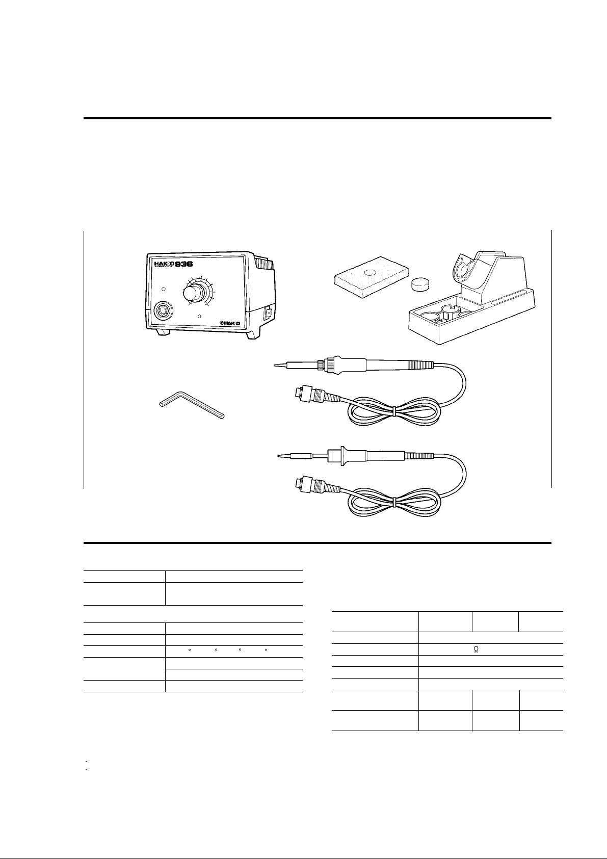
Packing List
Please check the contents of the HAKKO 936 package and confirm that all the items listed below are included.
HAKKO 936 Station …………………………………1
Soldering Iron (HAKKO 900 (S), 907 or 908) ……1
HAKKO Iron Holder (With Cleaning Sponge) ……1
Hex Wrench (1.5 mm,0.059 in.)……………………1
Instruction Manual …………………………………1
Cleaning Sponge
Iron Holder
Station
Hex Wrench
Specifications
Name HAKKO 936
Power Consumption 100,110,220-240V / 60W
120V / 65W
Station
936 Station / 936 Station ESD
Output Voltage 24V AC
Temperature Range 200 C~480 C/392 F~896 F
Dimensions 120(W)x93(H)x70(D)mm
4.7(W)x3.7(H)x6.7(D)in.
Weight (W/O Cord) 1, 300g (2.9 lbs.)
Iron/907,908
Iron/900 (S)
Soldering Iron
900S 907 908
900S-ESD 907-ESD 908-ESD
Power Consumption 24V AC-50W
Tip to Ground Resistance
Tip to Ground Potential
Heating Element Ceramic heater
Cord Assembly 1.2m (4 ft.)
Total Length
(7 in.) (7.5 in.) (7.9 in.)
Weight (w/o Cord) 25g 44g 54g
(w/o Cord)
Under 2
Under 2mV (TYP. 0.6mV)
176mm 190mm 200mm
(0.06 lbs.) (0.09 lbs.) (0.12 lbs.)
The tip temperature was measured using HAKKO 191 thermometer.
Specifications and design subject to change without notice.
1
Page 3
Page 4
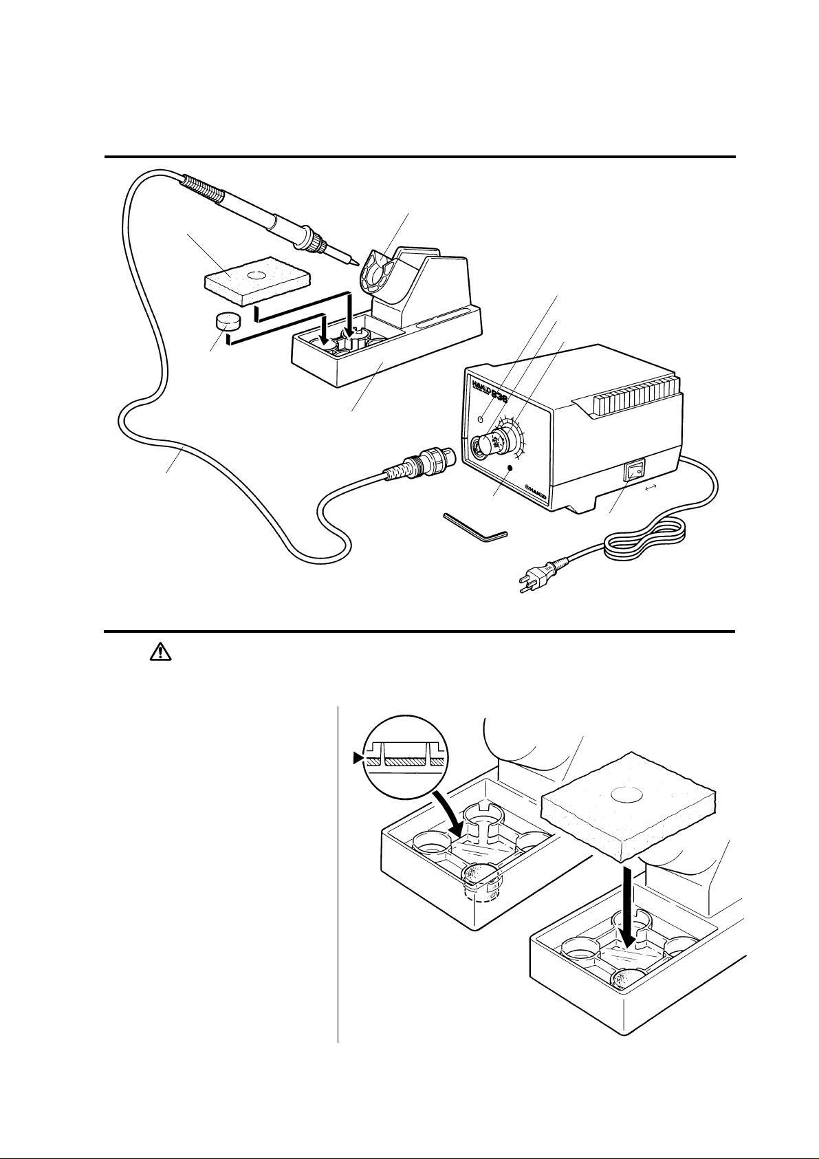
Names of Parts
Large Cleaning
Sponge
Small Cleaning
Sponge
Iron Holder Base
Cord Assembly
Iron Receptacle
CAL Pot Plug/Calibrator
LED Heater Lamp
Temp. Control Knob
Knob Mount
OFF ON
Power Switch
Hex Wrench
Setting up & Operating the HAKKO 936
CAUTION:The sponge is compressed. It will swell when moistened with water.
Before using the unit, dampen the sponge with the water and squeeze it dry.
Failure to do so may result in damage to the soldering tip.
A. Iron Holder
1. Small Cleaning Sponge
Dampen the small cleaning
sponge with water and then
squeeze it dry.
Place it in one of the 4 openings
of the iron holder base.
2. Add water to approximately the
level as shown. The small sponge
will absorb water to keep the
larger sponge above it wet at all
times.
* The large sponge may be used alone
(w/o small sponge & water).
3. Dampen the large cleaning
sponge and place it on the iron
holder base.
Note:The iron receptacles for the 900(S) and
the 907/908 soldering irons are different.
Be sure to use the proper one for each
type of soldering iron.
(Refer to Parts List).
3
Page 5

CAUTION : Be sure to turn off the power switch before connecting or disconnecting
the soldering iron. Failure to do so may damage the P.W.B.
B. Connections
1. Connect the cord assembly to
the receptacle.
2. Place the soldering iron in the
iron holder.
3. Plug the power cord into the
power supply. Be sure to ground
the unit.
C. Set the Temperature
1. Set the temperature control knob
to the desired temperature.
2. Lock the knob.
The HAKKO 936 station is
equipped with a temperature
control knob lock. After setting
the desired temperature,
tighten the hex nut on the
underside of the knob mount
using the supplied hex wrench.
Turn the nut clockwise to tighten
the knob lock.
Receptacle
Turn clockwise firmly
Align the grooves and pins,
and push straight in.
CAUTION : •Don't overtighten the knob lock.
•Don't attempt to turn the knob when the knob lock is on.
D. Turn on the Power
Switch.
The heater lamp blinks on and off
when the tip temperature reaches
the set temperature. The unit is now
ready to perform soldering work.
For greater convenience, and
soldering efficiency, two stations can
be securely stacked as shown.
CAUTION : The soldering iron must be placed in the iron holder when not in use.
4
Page 6

Tip Care and Use
•Tip T emperature
•Cleaning
•When Not in Use
•After Use
Maintenance
Inspect and Clean the Tip
CAUTION : Never file the Tip to
remove oxide.
High soldering temperatures can degrade the tip.
Use the lowest possible soldering temperature.
The excellent thermal recovery characteristics ensure efficient and
effective soldering even at low temperatures.
This also protects the soldered items from thermal damage.
Clean the tip regularly with a cleaning sponge, as oxides and carbides
from the solder and flux can form impurities on the tip. These impurities
can result in defective joints or reduce the tip's heat conductivity.
When using the soldering iron continuously, be sure to loosen the tip
and remove all oxides at least once a week.
This helps prevent seizure and reduction of the tip temperature.
Never leave the soldering iron sitting at high temperature for long
periods of time, as the tip's solder plating will become covered with
oxide, which can greatly reduce the tip's heat conductivity.
Wipe the tip clean and coat the tip with fresh solder.
This helps prevent tip oxidation.
1. Set the temperature to 250 C (482 F).
2. When the temperature stabilizes, clean the tip with the
cleaning sponge and check the condition of the tip.
3. If there is black oxide on the solder-plated portion of the tip,
apply new solder (containing flux) and wipe the tip on the
cleaning sponge. Repeat until the oxide is completely
removed. Coat with new solder.
4. If the tip is deformed or heavily eroded, replace it with a
new one.
Calibrating the Iron Temperature
The soldering iron should be
recalibrated after changing the iron,
or replacing the heating element
or tip.
5
1) Connect the cord assembly plug to the receptacle on the
station.
2) Set the temperature control knob to 400 C (750 F).
3) Turn the power switch to ‘ON’ and wait until the temperature
stabilizes. Remove the CAL potentiometer plug.
4) When the temperature stabilizes, use a straight-edge
(-) screwdriver or small plus (+) screwdriver to adjust the
screw (marked CAL at the station) until the tip thermometer
indicates a temperature of 400 C (750 F).
Turn the screw clockwise to increase the temperature and
counterclockwise to reduce the temperature.
Replace the CAL pot plug.
* We recommend the HAKKO191/192 thermometer for measuring the tip
temperature.
Page 7

Tips
The tip temperature will vary according to the shape of the tip. The preferred method of adjustment uses a tip
thermometer. (See “Calibrating the Iron Temperature” on page 5.)
A less accurate method involves adjusting the temperature control knob according to the adjustment value for each tip.
Example : When using a 900M-T-H tip at 400 C (750 F),
the difference between this tip and a 900M-T-B is -20 C (-36 F).
Set the temperature control knob to 420 C (786 F).
Refer to the chart for the correct adjustment values.
907
900M-T-0.8D
0 C
900M-T-1.2D
0 C
900M-T-1.6D
0 C
900M-T-2.4D
0 C
900M-T-3.2D
0 C
900M-T-1.2LD
-10 C/-18 F
900M-T-SB
0 C
900M-T-B
0 C
0.6(0.024)
0.7(0.028)
0.5(0.02)
0.5(0.02)
0.5(0.02)
0.7(0.028)
(0.047)
ø1.2
(0.031)
ø0.8
(0.047)
ø1.2
(0.06)
ø1.6
(0.09)
ø2.4
(0.12)
ø3.2
(0.08)
ø2
3
(0.2)
5
(0.25)
6.5
25(0.98)
R0.2(0.008)
R0.5(0.02)
17(0.66)
17(0.66)
(0.1)
17(0.66)
14(0.55)
17(0.66)
17(0.66)
17(0.66)
900M-T-LB
-10 C/-18 F
900M-T-0.5C
0 C
900M-T-0.8C
-10 C/-18 F
900M-T-1C
900M-T-1CF*
0 C
900M-T-1.5CF*
0 C
900M-T-2C
900M-T-2CF*
0 C
900M-T-3C
900M-T-3CF*
0 C
900M-T-4C
900M-T-4CF*
0 C
R0.2(0.008)
(0.02)
ø0.5
(0.031)
ø0.8
(0.04)
ø1
(0.06)
ø1.5
(0.08)
ø2
(0.1)
ø3
(0.16)
ø4
25(0.98)
45
45
60
60
45
45
45
15(0.6)
17(0.66)
15(0.6)
15(0.6)
17(0.66)
17(0.66)
17(0.66)
900M-T-K
+30 C/+54 F
900M-T-R
0 C
900M-T-RT
0 C
900M-T-SI
0 C
900M-T-I
-10 C/-18 F
900M-T-H
-20 C/-36 F
900M-T-1.8H
-10 C/-18 F
900M-T-S4
0 C
2(0.08)
3.5(0.13)
1.8(0.07)
(0.2)
ø5
45º
15(0.6)
(0.2)
ø5.1
(0.08)
2
17(0.66)
(0.1)
3.2
(0.17)
ø4.2
2
(0.08)
2
17(0.66)
(0.08)
R0.2(0.008)
13(0.51)
R0.2(0.008)
17(0.66)
1.2(0.04)
(0.29)
7.5
25
19(0.74)
1(0.04)
(0.29)
7.5
25
14(0.55)
R0.25(0.01)
(0.08)
ø2
15(0.6)
•900M tip Out Diam ø6.5
908
For heavy duty soldering HAKKO recommends the 908 iron with heavier tips.
900L-T-B
0 C
900L-T-2B
0 C
900L-T-2.4D
0 C
900L-T-3.2D
0 C
900S
900S-T-1.2D
0.4(0.016)
0 C
900S-T-1.6D
0.5(0.02)
0 C
R0.5(0.02)
20(0.8)
(0.08)
ø2
20(0.8)
(0.09)
ø2.4
(0.2)
5
0.5(0.02)
0.5(0.02)
(0.12)
ø3.2
8(0.3)
20(0.8)
20(0.8)
For micro soldering HAKKO recommends the 900S iron with fine tips.
(0.047)
ø1.2
17(0.66)
(0.06)
ø1.6
17(0.66)
900L-T-2C
900L-T-2CF*
-20 C/-36 F
900L-T-3C
900L-T-3CF*
0 C
900L-T-4C
900L-T-4CF*
0 C
900L-T-5C
900L-T-5CF*
0 C
900S-T-1C
0 C
900S-T-2C
(0.08)
0 C
(0.04)
ø2
ø1
60
15(0.6)
45
17(0.66)
(0.08)
(0.1)
(0.15)
(0.2)
900L-T-I
ø2
45
20(0.8)
ø3
45
20(0.8)
ø4
45
20(0.8)
ø5
45
15(0.6)
-20 C/-36 F
900L-T-K
+20 C/
+36 F
2(0.08)
R0.2(0.008)
(0.2)
ø5
20(0.8)
45
18(0.7)
•900L tip Out Diam ø8.5
*-These tips are tinned flat only.
900S-T-B
R0.5(0.02)
0 C
900S-T-I
0 C
17(0.66)
R0.2(0.008)
17(0.66)
•900S Tip Out Diam ø5.8
6
Page 8

Troubleshooting Guide
WARNING : * Disconnect the power plug before servicing.
Failure to do so may result in electric shock.
* If the power cord is damaged, it must be replaced by the manufacturer,
its service agent or similarity qualified person in order to avoid personal
injury or damage to the unit.
Problem 1.
The heater lamp does not
light up.
Problem 2.
The heater lamp lights up
but the tip does not heat up.
Problem 3.
The tip heats up intermittently.
Problem 4.
The tip is not wet.
Check 1. Is the power cord and/or connecting plug
disconnected ?
• Connect it.
Check 2. Is the fuse blown?
• Determine why the fuse blew and eliminate the cause, then
replace the fuse.
a. Is the inside of the iron short-circuited?
b. Is the grounding spring touching the heating element?
c. Is the heating element lead twisted and short-circuited?
Check 3. Is the soldering iron cord broken ?
• Refer to ‘Checking for breakage in the cord assembly.’
Check 4. Is the Heating Element broken?
• Refer to ‘Checking for breakage in the heating element.’
Check 3
Check 5. Is the tip temperature too high?
• Set an appropriate temperature.
Check 6. Is the tip clean?
• Refer to ‘Tip Care and Use’
Problem 5.
The tip temperature is too
low.
Problem 6.
The tip can not be pulled off.
Problem 7.
The tip doesn't hold the
desired temperature.
7
Check 7. Is the tip coated with oxide?
• Refer to ‘Inspect and clean the tip’
Check 8. Is the iron calibrated correctly?
• Recalibrate.
Check 9. Is the tip seized?
Is the tip swollen because of deterioration?
• Replace the tip and the heating element.
Check 8
Page 9

Checking for breakage of the heating element and cord assembly
Disconnect the plug and measure
the resistance value between the
connecting plug pins as follows.
If the values of 'a' and 'b' are outside
the above value, replace the heating
element (sensor) and/or cord
assembly. Refer to Procedures
1 and 2.
If the value of 'c' is over the above
value, remove the oxidization film by
lightly rubbing with sand-paper or
steel wool the points shown below.
1.
Broken Heating Element
5
4
3
2
1
a Between pins 4&5 (Heating Element) 2.5 - 3.5 (Normal)
b Between pins 1&2 (Sensor) 43 - 58 (Normal)
c Between pin 3&Tip Under 2
Disassembling the 907/908
12
7
8
9
6
10
11
Heating Element (Red)
1. Turn the nut (1) counterclockwise and remove the tip
enclosure (2), the tip (3).
2. Turn the nipple (4) counterclockwise and remove it from the
iron.
3. Pull both the heating element (6) and the cord assembly (11)
out of the handle (12). (Toward the tip of the iron.)
4. Pull the grounding spring (5) out of the D-sleeve.
Senser (Blue)
Measure when the heating element is at room temperature.
1. Resistance value of heating element (RED) 2.5 - 3.5
2. Resistance value of sensor (BLUE) 43 - 58
If the resistance value is not normal, replace the heating
element.
(Refer to the instructions included with the replacement part.)
After replacing the Heating Element,
1. Measure the resistance value between 1) pins 4 & 1 or 2
2) pins 5 & 1 or 2. If it is not , the heating element and
sensor are touching. This will damage the P.W.B.
2. Measure the resistance value 'a','b',and 'c' to confirm that
the leads are not twisted and that the grounding spring is
properly connected.
8
Page 10

Page 11

Parts List (Station/Iron Holder)
Note:Spare or repair parts do not include mounting
screws, if they are not listed on the description.
Screws must be ordered separately.
1
6
4
5
Hexagon Socket Set Screw
M 3 ~6 (1)
Part No.
Item No.
B2048 Upper Case 100,110,220~240V (Standard)
1
B2225 Upper Case / UL 120V (Standard / UL)
B2001 Upper Case E.S.D.
B2229 P.W.B.
2
B2003 Panel
3
B2006 Receptacle
4
B2004 Knob w / a screw
5
B2005 Knob Mount w / a screw
6
B2018 CAL Pot Plug
7
B2227 Grounding Plate
8
B2011 Transformer 100-24V
9
B2012 Transformer 110-24V
B2228 Transformer 120-24V (Standard / UL)
B2013 Transformer 120-24V (ESD)
B2014 Transformer 220~240-24V
B2088 Transformer 240-24V (Australia)
B2000 Lower Case* 100,110,220~240V (Standard)
10
B2226 Lower Case / UL* 120V (Standard / UL)
B2002 Lower Case* E.S.D.
B2015 Cord Stopper
11
B2016 Rubber Stopper set of 2
12
B1318 Power Cord 3 Wired Cord But No Plug
13
B1319 Power Cord 3 Wired Cord & American Plug
B2042 Power Cord 3 Cord & Australian Plug
B2043 Power Cord 3 Cord & European Plug
B2007 Fuse / 2A 100,110V
14
B2224 Fuse / 2A 120V (UL)
B2008 Fuse / 0.8A 220~240V
B2103 Wiring Board for Switch
15
B1084 Power Switch
16
B2017
17
*w / Rubber Stopper
Part Name Description
Hex Wrench
3
2
7
Hexagon Socket Head Cap Screw
M 2 ~8 (1)
10
Tapping Screw
(Fluted Point)
M 4 ~12 (4)
Binding Head
Tapping Screw (Fluted Point)
M 3.5 ~50 (4)
M 3.5 ~40 (4) for No.B2228
Transformer
8
9
14
12
17
Tapping Screw (Fluted Point)
M 3 ~12 (1)
11
15
16
13
Item No. Part No. Part Name For
1 C1141 Iron Holder 900S
C1142 Iron Holder 907,908
2 B2020 Iron Receptacle 900S
B2021 Iron Receptacle 907,908
3 B2019 Iron Holder Base 900S,907,908
4 A1042 Cleaning Sponge 900S,907,908
2
1
3
4
10
Page 12

Parts List (Iron)
900S
Item No. Part No. Part Name Description
1 900S-006 Nut
900S-006S Nut E.S.D.
2 Soldering Tip See. P.6
3 A1322 Heating Element Old part No.900S-H
4 900S-101 Terminal Board w/Cord Stopper
5 900S-001 Handle w/Handle Cover
900S-001S Handle w/Handle Cover, E.S.D.
6 900S-034 Handle Cover
900S-034S Handle Cover E.S.D.
7 900S-010 Cord Bushing (Not shown)
8 900S-039 Cord Asse'y (Not shown)
900S-039S Cord Asse'y E.S.D. (Not shown)
907,908
Item No. Part No. Part Name Description For
1 B1784 Nut 907
B1794 Nut 908
2 B1786 Tip Enclosure 907
B1787 Tip Enclosure 908
3 Soldering Tip See. P. 6 907
Soldering Tip See. P. 6 908
4 B2022 Nipple 907
B2033 Nipple 908
5 B2032 Grounding Spring 907,908
6 A1321 Heating Element
7 B2028 Terminal Board w/Cord Stopper 907,908
8 B2023 Handle w/Handle Cover 907
B2024 Handle w/Handle Cover, E.S.D. 907
B2025 Handle w/Handle Cover 908
B2026 Handle w/Handle Cover, E.S.D. 908
9 B2027 Handle Cover 907,908
10 B2031 Cord Bushing 907,908
11 B2029 Cord Asse'y 907,908
B2030 Cord Asse'y E.S.D. 907,908
Old part No.900M-H,900L-H
907,908
Wiring Diagram
P.W.B.
Ground
®
HEAD OFFICE
4-5, SHIOKUSA 2-CHOME, NANIWA-KU, OSAKA, 556-0024 JAPAN
TEL: (06) 561-3225 FAX: (06) 561-8466
OVERSEAS AFFILIATES
U.S.A.: AMERICAN HAKKO PRODUCTS, INC.
25072 ANZA DR. SANTA CLARITA, CA 91355, U.S.A.
TEL: (805) 294-0090 FAX: (805) 294-0096
Toll Free (800)88-HAKKO
4 2 5 5 6
www. hakkousa.com
S'PORE: HAKKO PRODUCTS PTE., LTD.
1, GENTING LINK #02-04, PERFECT INDUSTRIAL
BUILDING, SINGAPORE 349518
TEL: 7482277 FAX: 7440033
11
24V
AC
TR
HONG KONG: HAKKO DEVELOPMENT CO., LTD.
ROOM 1504 EASTERN HARBOUR CENTRE,
28 HOI CHAK STREET, QUARRY BAY, HONG KONG.
TEL: 2811-5588 FAX: 2590-0217
PHILIPPINES: HAIKU PHILS TRADING CO., INC.
NO. 415 WINDSOR TOWER CONDOMINIUM,
163 LEGASPI ST., LEGASPI VILLAGE MAKATI,
METRO MANILA, PHILIPPINES
TEL: 2-817-07-12 FAX: 2-810-76-49
MALAYSIA: HAKKO PRODUCTS SDN BHD
MALAYSIA HEAD OFFICE: PETALING JAYA
LOT 35/1 THE HIGHWAY CENTRE JALAN 51/205 46050
PETALING JAYA WEST MALAYSIA
TEL: 03-7941333 FAX: 03-7911232
PENANG BRANCH: TEL: 04-644 6669 FAX: 04-644 8628
JOHORE BAHRU BRANCH: TEL: 07-236 7766 FAX: 07-237 4655
Transformer
3 Core
SEP., 1998
 Loading...