

Haier 3U19FS2ERA, 5U34HS2ERA, 4U30HS2ERA, 3U24GS2ERA, YR-HD Service Manual

Super Match
SYJS-11-2015REV.D
Edition:2015-11
3U19FS2ERA 3U24GS2ERA
4U30HS2ERA 5U34HS2ERA

Super Match
6.Controller
YR-HD
Loading of the battery
1
2
3
4
Remote controller
Remove the battery cover;
Load the batteries as illustrated.
2 R-03 batteries, resetting key
(cylinder);
Be sure that the loading
is in line with th
e" + "/"-";
Load the battery,then put on the cover again.
The distance between the signal transmission head and the receiver hole should be within 7m without any obstacle as well.
When electronic-started type fluorescent lamp or change-over
type fluorescent lamp or
wireless telephone is installed in the
room, the recei
ver is apt to be disturbed in receiving
the signals,
so the distance to the indoor unit should be shorter.
Note:
Full display or unclear display during operation indicates the
batte
ries have been used up.
Please change batteries.
If the remote controller can't run normally during operation, please
remove the batteries and
reload several minutes later.
lpsid edoM..1
lpsid gnidnes langiS..2
4.FAN SPEED display
. LOCK displ5.
6.TIMER OFF display
TIMER ON display
LO MED HI
7.
6. LOCK but16.
Used to lock buttons and LCD display.
5. RESET but25.
When the remote controller
appears abnormal, use a sharp
pointed article to press this button
to reset the remote
tub RUOH.2.22
Operation mode
AUTO FANCOOL DRY
Remote controller
HEAT
Hint:
Remove the batteries in case won't be in use for a long period. If
there is any display after taking-out, just press reset key.
1
2
3
4
5
9
10
11
12
13
14
15
16
17
22
23
24
25
19
20
21
8
18
7
6
Control the lightening and extinguishing
of the indoor LED display board.
3. SWING display
8
.
..9
QUIET but
tub TAEH.0.01
1. COOL but11.
2. AUTO but12.
tub NAF.3.31
4. TIMER but14.
tub HTLAEH.5.51
7. LIGHT but17.
8. POWER ON/OFF but18.
9. DRY but19.
0. TEMP but20.
tub GNIWS.1.12
tub NOITCNUF ARTXE.3.32
CANCEL/CONFIRM button24.
1
2
3
AUTO
Function: Auto, health airflow
upwards and downwards sending
function,sleep function,
air-refresh(reserved function)
Fahrenheit Celsius conversion
Power setting function
Function: Setting and cancel to the
timer and other additional functions.
Display
circulated
On the remote control do not have the functions of HEALTH.
Operation mode
Remote controller
QUITE
POWER
Supplemented
SLEEP
electrical
heating
HEALTH
TEMP display
Additional functions display
Press FAN button. For each press, fan speed
changes as
follows:
Remote controller:
Press
button
Every time the button is pressed, temp.setting
increase 1
o
C,if kept depressed, it will increase
rapidly
Every time the button is pressed, temp.setting
decrease 1
o
C,if kept depressed, it will
decrease rapidly
Select a desired temperature.
4.Fan speed selection
3.Select temp.setting
Air conditioner is running under displayed fan speed.
When FAN is set to AUTO, the air conditioner
automatically adjusts the fan speed according to room
temperature.
1. Unit start
Press ON/OFF on the remote controller, unit starts.
/
Base Operation
Remote controller
Operation
Mode
AUTO
Remote
Controller
Note
COOL
DRY
HEAT
FAN
Under the mode of auto operation, air conditioner
will automatically select Cool or Heat operation
according to room temperature
When FAN is set
to AUTO the air conditioner
automatically adjusts
the fan speed according to room
temperature.
In DRY mode, when room temperature becomes
lower than temp.setting+2
o
C, unit will run
intermittently at LOW speed regardless of FAN
setting.
In FAN operation mode , the unit will not operate in
COOL or
HEAT mode but only in
FAN mode ,
AUTO is not available in
FAN mode.
And temp.
setting is disabled. In FAN mode, sleep operation
is not available.
In HEAT mode, warm air will blow out after a short
period of the time due to cold-draft prevention function.
When FAN is set to AUTO, the air conditioner automatically
adjusts the fan speed according to room temperature.
1
4
3
3
LOW
MED HI
AUTO
2.Select operation mode
2
COOL button:Cooling mode
HEAT button: Heating mode
DRY button: Dehumidify mode
Display
circulated
135

Super Match
Sleep Operation
If the wind speed is high or middle before setting for the
sleep, set for lowing the wind speed after sleeping.
If it is low wind, no change.
Set the wind speed change when sleeping5.
Operation Mode
1. In COOL,DRY mode
SLEEP operation starts
SLEEP
operation starts
SLEEP
operation stops
SLEEP operation stops
Approx.6hrs
1 hr
1 hr
1 hr
3 hrs
3 hrs
Rises 1OC
Rises 1
O
C
Rises 1OC
Temp.setting
Temp.setting
Unit stop
Unit stop
In COOL, DRY mode
In HEAT mode
Decreases 2OC
Decreases 2
O
C
1 hr
3.
2.
In HEAT mode
In AUTO mode
4. In FAN mode
It has no SLEEP function.
Note
When TIMER function is set, the sleeping function can’t be
set up .After the sleeping function is set u
p
,
if user resets
TIMER function, the sleeping function will be cancelled; the
machine will be in the state of
timing-on.
POWER/QUIET Operation
1 hours after SLEEP mode starts,temp.will become
higher than temp.setting.After another 1 hours,temp.rises
O
C
by 1 futher.The unit will run for further
6 hours then stops
Temp. is higher than temp.setting so that room temperature
won’t be too low for your sleep.
1 hours after SLEEP mode starts,temp will become 2
lower than temp.setting.After another 1 hours,temp
decrease by 2
rises
O
C
by 1 futher.The unit will run for further 3 hours then
stops.Temp.is lower than temp. setting so that room
temperature won’t be
too high for your sleep.
The unit operaters in corresponding sleep mode
adapted to the automatically selected operation
mode.
O
C futher.After more another 3 hours,temp.
1O
C
O
C
button to enter additional options, when Press
cycle display to , will flash. And then press
enter to sleep function.
(1)
POWER Operation
When you need rapid heating or cooling, you can use this function.
(2)
QUIET Operation
You can use this function when silence is needed for rest or reading.
Note :
During POWER operation, in rapid HEAT or COOL mode,
the room will show inhomogeneous temperature distribution.
Long period QUIET operation will cause effect of not too
cool or not too warm.
Press QUIET button, the remote controller will show ,
and then achieve to the quiet function. Press again this
QUIET button , the quiet function will be cancelled.
Press button to enter additional options, when cycle
display to , will flash,and then press ,enter to
power function. When cancel the function, please enter
additional options again and to cancel power function.
136

Super Match
1.After unit starts, select your desired operation mode.
2.Press TIMER button to change TIMER mode. Every
time the button is pressed, display changes as follows:
Remote controller:
BLANK
0.5h
0.5h 0.5h
TIMER ON TIMER OFF TIMER ON-OFF
Then select your desired TIMER mode (TIMER ON or
"or " "will flash.TIMER OFF or TIMER ON-OFF). "
sserP.3 erP.3.3 button to set time.
Press the button for each time, settiing time in the first
12 hours decreased by 0.5 hour every time, after 12
hours,decreased by 1 hour every time.
It can be adjusted within 24 hours.
Hints:
After replacing batteries or a power failure happens, time
setting should be reset.
According to the Time setting sequence of TIMER ON or
TIMER OFF, either Start-Stop or Stop-Start can be achieved.
Timer On/Off On-Off Operation
All the products are in conformity with the following
European provision:
- Low Voltage Directive 73/23/EEC
- Low Voltage Directive 2006/95/EC
-Electomagnetic CompatibilitY 89/336/EEC
-Electomagnetic CompatibilitY 2004/108/EC
ROHS
The products are fulfilled with the requirements in the
directive 2002/95/EEC of the European parliament and of
council on the Restriction of the use of Certain Hazardous
Substances in Electrical and Electronic Equipment (EU
RoHS Directive)
WEEE
DISPOSAL REQUIREMENTS:
Your air conditioning product is marked with this
symbol.This means that electrical and electronic
products shall not be mixed with unsorted
household waste. Do not try to dismantle the
system yourself : the dismantling of the air
1
1+2=
kg
2
kg
2=
B
C
D
F E
R410A
1=
kg
A
This product contains fluorinated greenhouse gases covered by
the Kyoto Protocol. Do not vent into the atmosphere.
Refrigerant type:R410A
GWP* value:1975
GWP=global warming potential
Please fill in with indelible ink,
1 the factory refrigerant charge of the produc•
• 2 the additional refrigerant amount charged in the fiel and
• 1+2 the total refrigerant charg
on the refrigerant charge label supplied with the product.
The filled out label must be adhered in the proximity of the product
charging port (e.g. onto the inside of the stop value cover).
A contains fluorinated greenhouse gases covered by the Kyoto
Protocol
B factory refrigerant charge of the product: see unit name plate
C additional refrigerant amount charged in the field
D total refrigerant charge
E outdoor unit
F refrigerant cylinder and manifold for charging
IMPORTANT INFORMATIONREGARDING THE REFRIGERANT USED
In accordance with the directive 2002/96/CE of the European
parliament, herewith we inform the consumer about the disposal requirements of the electrical and electronic products.
conditioning system,treatment of the refrigerant, of oil and of
other part must be done by a qualified installer in
accordance
with relevant local and national legislation. Air conditioners
must be treated at a specialized treatment facility for reuse,
recycling and recovery. By ensuring this product is disposed
of correctly, you will help to prevent potential negative consequences for the environment and humen health. Please
contact the installer or local authority for more information.
Battery must be removed from the remote controller and disposed of separately in accordance with relevant local and
nationl legislation.
Contains fluorinated greenhouse gases
covered by the Kyoto Protocol
Healthy airflow Operation
1.Press to s.1 erP.1
Setting the comfort work conditions.
The setting of healthy airflow function2.
Notice: Do not direct the flap by hand. Otherwise, the
grille will run incorrectly. If the grille is not run correctly, stop
for a minute and then start, adjusting by remote
controller.
Note:
itisop eht ,noitcnuf wolfria yhtlaeh eht gnittes retfA.1.1
grill is fixed.
4.In cooling and dry, using the air conditioner for a long
The cancel of the healthy airflow function3.
2.In heating, it is better to select the
3.In cooling, it is better to select t3.
mode.
mode.
TIMER OFF-ON
0.5h
Press the button for each time, setting time in the first
12 hours increased by 0.5 hour every time, after 12
hours,increased by 1 hour every time.
button and confirm theAfter adjust the time,press
time ON or OFF button will not flash any more.
Confirm timer setting4.
5.Cancel timer setting
Press the timer button by times until the time display
eliminated.
button to enter additional options,Press this Press
button continuously, the louvers location will cycle between
in the following three locations, to choose the swing location
button to confirm.what you needed,and then press
Press button to enter additional options,Press this
button continuously, the louvers location will cycle between
in the following three locations again,and then press
button to cancel.
Healthy
airflow
upwarder
Healthy
airflow
downwarder
Present
position
137

Super Match
Parts and Functions
Display of the wire controller
The models in the manual don't have health, lter reset and Air change function.
Air volume display
Running mode display
Display the setting speed
Show the selected mode
Health function display
Unit number display
Centralized address
display
System address
display
Temperature
display
Display the room
temperature, setting
temperature, and
unit number
Timing operation
display
Inspection status display
Wind swing display
Air change display
Centralized display
Running display
Standby display
Demand display
Show timing operation
content
When forced to run,"DEMAND"
will be displayed , or show HH/LL
in the temperature zone.
When controlled by centralized
controller, and chosen by "centralize or
lock" mode, this information is shown.
When the compressor runs, it displays.
When the unit is on power and in
"abnormity mode", or outdoor unit
malfunction show alarm , "standby" is
shown to reect no need to unit.
When in preheating
status, "preheating" is
shown.
"Defrost" is shown
when defrosting.
Filter screen warning
sign
When the sign is
shown, please clean
the lter screen
Remarks
YR-E14
138

Super Match
Parts and Functions
Buttons of the wire controller
Mode switch
Choose running mode
Fan speed switch
Change wind speed
Swing switch
Open and close air ap
TEMP switch
Used for changing set temperature
Time switch
It is used to regulate setting time.
Air change switch
It is used to open and close air
change function. The mode is as
follows:
No display-air change (automatic)air change (RECOVERY)-air
change (NORMAL)
ON/OFF switch
Do on and off function. The unit is
on when pressing it; and is off
when pressing it again.
Reset key
When in abnormal state, push the
reset key with a spike, which may
return the unit to normal
Clock, timing and address setting
Health switch
Used to control oxygen
function and negative ion
Timing switch
It is used for choosing
timing running
Self-inspection
switch
It is used for inspection
service
Filter reset
After cleaning air inlet
and lter, press
this switch. The unit
begins to run
139

Super Match
Operation
ON/OFF operation
Press ON/OFF switch on line controller directly
The line controller displays the running state in the latest
time (timing and swing state may not be displayed).
1. Press "ON/OFF" switch.
The air conditioner starts operating, and the light on the
wired controller is on.
2.Choose operation mode.
Press "mode"switch to change to
"AUTO"---"FAN ONLY"---"COOL"---"DRY"---"HEAT".
3.Press "TEMP" switch
Change set temperature:press TEMP
or TEMP every
time, [SET] will display,and set temperature will
increase/reduce 1
5.Press "SWING" switch on the line controller to
swing the wind screen.
6.Press "ON/OFF"switch, off.
The light on the line controller is off.
4.Press "FAN SPEED" switch
FAN ONLY Operation:
Press "FAN SPEED" switch to change to
"HIGH"--"MED"--"LOW"--"HIGH"
In AUTO,COOL,DRY,HEAT Operation:
Press "FAN SPEED" switch to change to
"AUTO"--"HIGH"--"MED"--"LOW"--"AUTO"
Note
Several seconds after the operation of the line controller,
the setting of the unit will change.
Remarks
Avoid pressing "ON/OFF" switch frequently.
Do not press line controller or switches by sharp objects.
The temperature is on the basis of the setting value. The wind temperature may not reach the setting value because of
the outer air conditioner and system protection.
When the wired controller is power on, the screen fully displays it for two seconds. and clock zone "8888"-"888"-"88"-"8"
icker for 30 seconds. All the switches are invalid at the time.
140

Super Match
Operation
Present time setting
The timing is based on the real time. Thus, the real time should be regulated in advance.
The clock regulation steps are as follows:
1.Press "CLOCK" switch
2.Press "
" and " " to regulate the time.
3.Press "SET" switch. The setting is achieved.
"CLOCK" ickers, and the time displayed is the real time.
The time increases a minute each time you press "
" switch.
The time decreases a minute each time you press "
" switch.
If not in timing, the screen displays the real time.
If in timing, the screen displays the timing time.
If you want to know the real time, go to the rst step.
Setting of power failure compensation function
When SW1-6 on PCB of wire controller is OFF, it will be in power failure compensation. If the SW1-6 is ON, it has no
compensation function.
When the power is on after blackout, the unit will return to the former state if compensation function is set. Otherwise, it
will stop. When restarting the unit, press "ON/OFF" switch on wired controller.
Notes
141

Super Match
Operation
Timing setting
OFF timing: when a set time has elapsed, the unit stops running.
ON timing: when a set time has elapsed, the unit starts.
Press "ON/OFF" switch rstly,
and set up operation mode.
Please regulate the clock in
advance before using the
timing function.
1.Press "TIMER" switch.
1.Press "TIMER" switch.
2.Set up "TIMER"
3.Time setting is achieved. Press"setting"switch.
The display changes with the following sequence:
ON
OFF
on
OFF
on
OFF
CYCLE
no display
When timing ON or timing OFF ickers, press " " or " " to
regulate the time
Press" "or " "set up ON/OFF time.
The setting time increases ten minutes each time you press " "
switch.
The setting time decreases ten minutes each time you press" "
switch.
When setting timing ON and timing OFF at the same time,
press "timing" switch to change the setting item.
If you want to change the timing mode to normal operation,
press "timing" until there is no timing display. When the
timing is invalid, the mode is in normal operation.
parts of wired controller explanation :
Cancel timing
1.The unit starts or stops at the setting time. Meanwhile, it displays the timing time.
2."ON Timing, OFF timing and circulation"means that the unit is on and off at the setting time everyday.
The shorter setting time will be carried out rstly.
If the ON timing and OFF timing are the same, the setting is invalid.
Even in timing condition, you may start or close the unit through pressing "ON/OFF" switch.
Note
142

Super Match
Operation
ON
ON
ON
ON
ON
ON
OFF
OFF
OFF
OFF
OFF
OFF
Query indoor malfunction history:
In the state of power on or power off, press [CHECK] button, enter the malfunction-querying mode of all indoor units in
the group. Then [CHECK] and [UNIT NO.] will display, and the actual indoor numbers will be displayed in some sequence
(unit number is in decimals). At the same time, in the time region, there will be the current malfunction and the latest time
malfunction, the displaying format is [XX:YY], in which XX stands for the current malfunction, if normal, it will display "--";
YY stands for the latest time malfunction. The failure code of every unit will display for 3 seconds. After the failure codes
of all indoor units in the whole group are displayed, the mode will quit automatically.
How to change the function switches?
ON
OFF
1. Switches or jumper wire must be adjusted when the wire controller is powered off. If the wire controller is
powered on, the above operations will be invalid.
2. Function difference between master wire controller and slave one:
Slave wire controller
All of functionsFunction
Master wire
controller
Contrastive
items
Only with below functions: ON/OFF, MODE, FAN SPEED,
SET TEMP., SWING
No.
SW1-2
SW1-8
SW1-7
SW1-6
SW1-5
SW1-4
SW1-3
SW1-1
State of switchType
Select the master or
the slave controller
Select the controller
mode
Room temperature
display option
Temperature sensor
position option
26
o
lock
Auto restart
Factory Setting
Factory Setting
Set as the slave controller
Set as the master controller
Standard controller
Air handler controller
Visible room temperature
Invisible room temperature
Unavailable 26
o
lock
Available 26
o
lock
Sensor of the controller
Sensor in the unit
Unavailable
Available
Default setting
Default setting
Function description
Note
143

Super Match
Installation Manual For Wire Controller
1. Take down wire controller from the holder
2. Install the controller holder
According to the position of 2 screw holes on the holder, drill 2 holes on the wall, and strike the wood stopper to the holes
respectively.
Then align the 2 screw holes of wired controller holder to the wood stopper, x the holder on the wall with wood screw.
3.Wiring instruction
Use shielded wire between indoor and wire controller. And be earthed on one side, or the unit will not work normally
because of interference.
Note:
Try a wall as at as possible for installation. Don't use excessive force to tighten screws, otherwise, the holder will be
damaged.
Note:
Conrm the terminal connection rmly, and do not get in tough with shielded wire.
Don't touch the PC panel with your hands.
4.Place wire controller on the holder, and pay attention not to pressing any wires.
5. Wiring connections of wire controller:
Wire controller
Screw holesScrew holes
shielded wire
grounding
Bracket
TYPE1: For AD09~24SS1ERA(N)(P) AD09~24SS1ERA(N) AD12/18MS1ERA AD12/18MS1ERA(D) AD24MS2ERA AD24MS2ERA(D)
144

Super Match
Installation Manual For Wire Controller
There are three methods to connection wire controller and the indoor units:
A.One wired controller can control max. up to 16 sets of indoor units, and 3 pieces of polar wire must connect the wire
controller and the master unit (the indoor unit connected with wire controller directly), the others connect with the master
unit through 2 pieces of polar wire.
B. One wire controller controls one indoor unit, and the indoor unit connects with the wire controller through 3 pieces of
polar wire.
C. Two wired controllers control one indoor unit. The wire controller connected with indoor unit is called master one, the
other is called slave one. Master wire controller and indoor unit; master and slave wire controllers are all connected
through 3 pieces of polar wire.
6. Communication wiring:
The wire controller is equipped with special communication wiring in the accessories. 3-core terminal (1-white 2-yellow
3-red) is connected with the terminal A, B, C of wire controller respectively.
The communication wiring is 5 meter long; if the actual length is more than it, please distribute wiring according to below
table:
*One side of the shielded sheet of communication wire must be earthed.
Communication wiring length(m) Dimensions of wiring
100 0.3mm
2
x3-core shielded wire
100 and <200 0.5mm2x3-core shielded wire
200 and <300 0.75mm2x3-core shielded wire
300 and <400 1.25mm2x3-core shielded wire
400 and <600 2mm2x3-core shielded wire
TYPE 2: For other indoor units.
145

Super Match
Read this manual before installation and operation
Make sure that it is well kept for later reference
YR-E16
146

Super Match
Parts and Functions
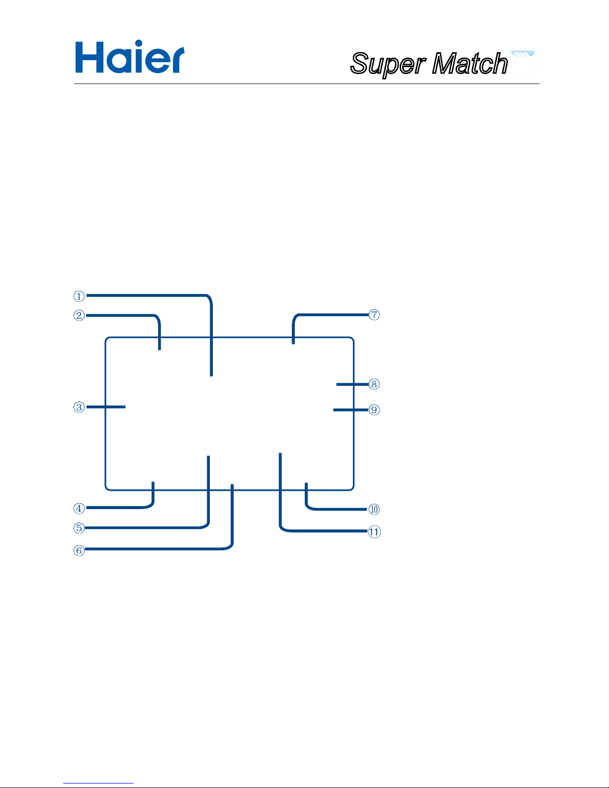
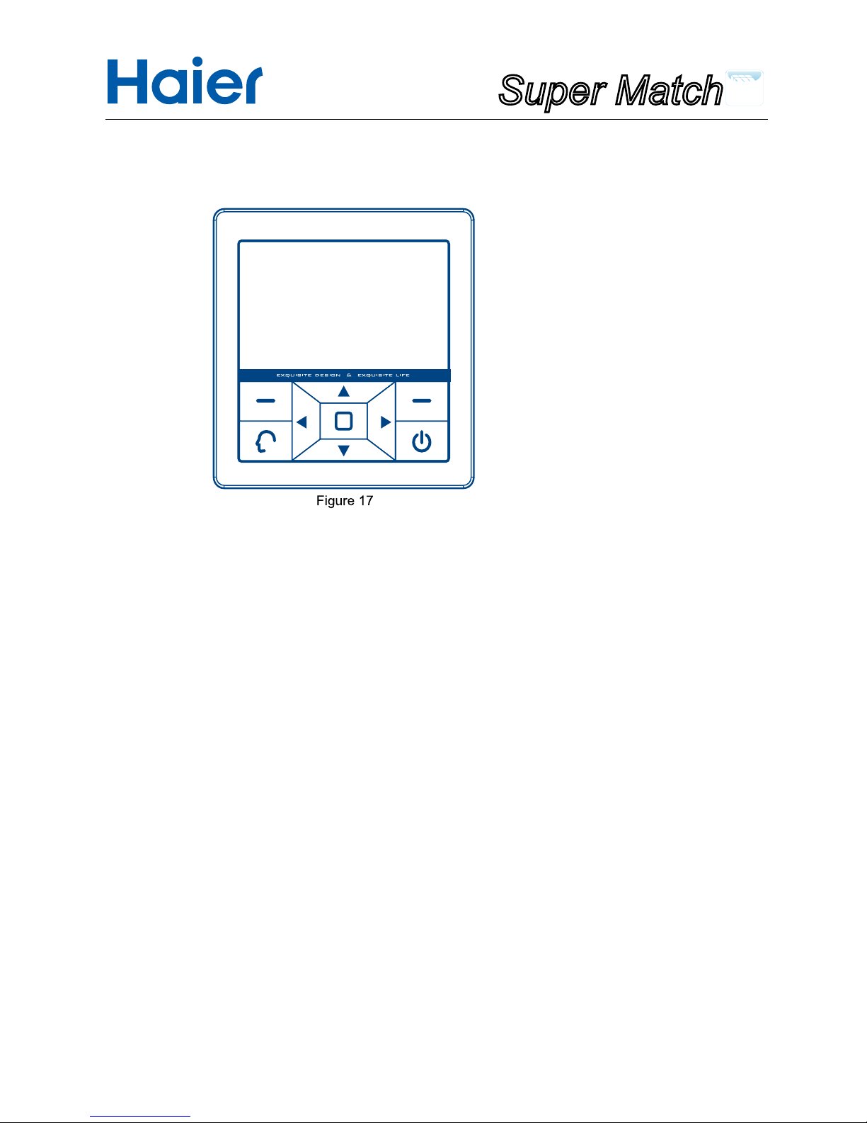
•Key instructions for the wired controller
①
Up direction key:
It provides temperature rise function in the mode switching interface; if this key is pressed in the menu interface,
the cursor moves upward; It raises the numerical value when adjusting value.
②
Left function key:
According to the function prompt above the key, it provides mode switching function in the mode interface and
return function in the menu interface.
③
Left direction key:
It provides air speed switching function (when the right key is the swing key); it provides cursor leftward
movement function in other interfaces.
④
Intelligent key:
In the main menu interface, press this key to initiate the intelligent work mode (excluding single cold mode and
single heat mode and when there is no intelligent mode for indoor DIP switch setting.).
⑤
Down direction key:
It provides temperature drop function in the mode switching interface; if this key is pressed in the menu
interface, the cursor moves downward; It reduces the numerical value when adjusting value.
⑥
Right function key:
According to the function prompt above the key, it provides swing on/off function or air speed (when both the
left-right and up-down options are not selected in the air direction setting interface) switching in the mode
interface; it provides the conrmation function in the menu interface and it provides the "Next step" fuction in the
interface of "service Set -Password-Original password".
147
Super Match
⑦
Right direction key:
It provides air speed switching function (when the right key is the swing key); it provides cursor rightward
movement function in other interfaces.
⑧
Startup & Shutdown key:
It provides startup and shutdown function. When in shutdown state, press this key to start it up; press the key
again to shut it down.
⑨
Menu/main interface/input key:
It provides menu function in the mode interface; in the menu interface, it will enter the main interface; in the
password interface, it functions as the characters input key refering to the prompting character above the key.
•Main interface display
①
Online units display area:
It displays the number of the units controlled by one wired controller.
②
Special function/fault icon display area:
Such as weekly timer, Swing, sleep, children lock, force, air exchange and energy conservation; each icon
corresponds to a function; if a fault appears, the fault icon is displayed.
③
Mode display area:
Intelligent, heating, cooling, dehumidication and fan modes (the single cold mode has only cooling,
dehumidication and fan modes; the single heat mode has only heating and fan modes;except when DIP
switch of indoor unit has mode limit. )
④
Left function key function prompt area
Parts and Functions
148

Super Match
Parts and Functions
⑤
Set temperature display area:
The range of adjustment is 16
O
to 30O(except when in the setting of energy conservation function).
⑥
"Menu/main interface/input"key function prompt area:
if any function is prompted here, press the menu/main interface/input to execute the prompted function
⑦
Date and time display area.
⑧
Status indication area:
Indication of the master/slave unit of the wired controller, lter screen cleaning prompt/defrosting status
indication/forced defrosting issuance prompt, operation/standby status indication.
⑨
Swing:
Dynamic display during setting of swing (single swing, or both swings or no swing, depending on the set air
direction)
⑩
Right function key function prompt area
Air speed display area:
Automatic, weak air, moderate air, strong air; the fan mode has no automatic air
149

Super Match
Parts and Functions
•Explanation of the icons of the wired controller
•Display and adjustment of air speed
1. Default air speed upon initial energization
Mode Cooling Heating Intelligent Dehumidication Fan
Air speed Strong air Weak air
Automatic
air
Automatic air Weak air
2. Press the "left-right"key to set air speed
Strong air:
Moderate air: Weak air:
Automatic: i.e. automatic cyclic display in weak→moderate→strong→weak
air.
3. In the fan mode, automatic air is unavailable. The other displays are the same with the above.
4. For some models, the right function key is the "air speed?key (i.e. the bottom right corner of the interface
displays "speed", so air speed is adjusted using the right function key, instead of left-right direction key.
150

Super Match
Operation
3.Time setting of timing switch
A. After the timing items for week have been set, each group of set timing information displays 5 seconds
cyclically; when it is displayed in the timing information group, press the "Downward"key to initiate the time
setting of the timing switch of the current group;
B. The cursor is ickering where it stays; when the right function key, as an "Enter"key, is pressed, the cursor
becomes static, which indicates that it is in the adjustment state; press the upward-downward key to adjust the
time and temperature. After adjustment of time and temperature, move the cursor leftward and rightward to
conrm the time and temperature.
C. For adjustment of time, keep the "Upward"key or "Downward"pressed down for 5s, the clock change will
accelerate, with acceleration frequency of 10times/s.
D. During icker of the cursor, move upward, downward, leftward or rightward to select the circle below; use
the right function key, as an "Enter"key, to conrm or cancel the setting;
represents setting valid and
represents setting invalid.
E. If
is present in a timing item containing week, this means the corresponding timing information is valid.
4. Deletion of timing information
If, in a "Weekly timer"interface, the cursor is at"
"press the leftward-rightward key to select ; then press
"Enter"key to pop out the window as shown in Figure 4. Then press the left key or right key to delete or retain the
timing information.
5. Timing switch on/off conict prompt: if the timing has been set in such a way that timing on/off setting
conicts occur at the same time on the same day, those shown in Figure 5 will pop out.
Note: In the time setting state of week timing(cursor still), if no order input for 1 minute, screen saver will be
activated and it will automatically return to main interface; In which state, non-conicting orders are effective and
otherwise no interface popping out; Latter input conicting orders are ineffective with NON-SET state displaying
Figure 4
151

Super Match
Operation
6. Prior to setting of weekly timer, please make time setting through main interface→ Menu→ Time
interface.
7. The slave unit of the wired controller has no setting of weekly timer.
8. Weekly timer setting done, it needs to exit the weekly timer interface to execute the order.
•Current clock setting
1. Proceed through main interface→Menu→Time→"Enter" key to enter, which is shown in Figure 6,
2. Default setting starts with the "Year"value, press the "Rightward key:to select "Year"-Month"→"Day"→"Hou
r"→"Minute"→"Week";or press the "Leftward key"to select "Week"→"Minute"→"Hour"→"Day"→"Month"→"Ye
ar"
3. When the time to be changed has been selected, press the "Upward key"or "Downward key"to adjust the
time;
4. After all the times have been adjusted, press "Enter"key to complete the setting.
152

Super Match
Operation
•Service setting
1. Proceed through main interface→Menu→Other→enter password→press
"Enter"key→Service Set→press "Enter"key to initiate the setting, which is shown in Figure
7.
2. Password setting
A.Common users are provided with a four-digit password which is initially 1234; high-class users are provided
with a six-digit password 841226 which can be operated by the technical personnel only.
B. Press the "Upward"key or "Downward"key to select "Password"and press "Enter"key to initiate password
setting, which is shown in Figure8. Password setting is intended for changing only the password of a common
user.
C.Press the "Leftward"key and "Rightward"key to select in the line of numbers; press the "Input"key to x the
selected numbers in the password box. When password entry is completed, press the right key to proceed with
"Next step" If the original password is input incorrectly, a window prompting "Wrong password"will pop out as
shown in Figure 9. Press "Enter"or "Cancel"in this window to return to the gure 8.
D.If the "Original password"is entered successfully, a window will pop out as shown in Figure 10 prompting "New
password? enter the password in the same way as described above and then press "Enter"key again to conrm
successful setting of new password or press "Cancel" key to cancel the password setting.
153

Super Match
E. If the new password has been set successfully, a window prompting "New password set Successfully!", as
shown in Figure 11 will appear; press "Enter"or "Cancel"to return to the previous menu
3. Restore the initial password
A. Select "Password recovery" as shown in Figure 7 and then press "Enter" key to enter the interface as shown
in Figure 12; press the left key "Cancel" or the right key "Enter" to cancel this operation or conrm restoration
of the initial password.
B. This operation here is used for restoring only the password of a common user
•Fault code query:
Proceed through main interface→Menu→Other→enter password→press "Enter" key→Error code→enter 14.
The password entry interface is shown in Figure 13 and the entry method is the same as password setting.
1. Use the "Leftward"key and "Rightward"key to check the fault codes inside the unit; where <1> can be 1 to 16,
which is the address code within the wired controller group.
2. In the current interface, keep both the "Left"key and "Right"key pressed down for 5 seconds to clear the
historic faults record.
Operation
154

Super Match
3. A common user can view the current faults and historic
faults; a high-class user can view 10 historic faults, using
the "Downward" key and "Upftward" key. If a common user
presses the "Downward" key, a window as shown in Figure
15; a high-class user can enter his/her password to view ten
historic faults.
•Air direction setting
1. Proceed through main interface→Menu→Swing→press "Enter" key; the default air direction is up/down. If
a left/right air deector is being controlled, the "Left/right?option can be selected.
2. If only the left/right direction is selected when setting the swing function, only the left/right air deector will
swing; if only the up/down direction is selected when setting the swing function, only the up/down air deector
will swing; if both the left/right direction and up/down direction are selected, both the left/right air deector and
up/down air deector will swing (for different models, some units have only the left/right air deector or up/
down air deector; the setting needs to be made consistent with the specic model).
3.
Indicates "Selected" indicates "Unselected?
4. If both the up/down direction and left/right direction are not selected, the bottom right corner of the main
interface will display the air speed; Use the right key to switch the air speeds.
Operation
155
Super Match
•Sleep setting
1. Proceed through main interface→Menu→Sleep→press "Enter" key to initiate this mode; The default state is
shutdown.
2. Use the up ,down, left and right keys to adjust the cursor; The location where the cursor stays has the circle
ickering; press the "Enter" key to select the time and switch between on/off.
3. The selected time 0.5, 1, 1.5, 2, 2.5 and 3 mean that the wired controller will shut down in 0.5/1/1.5/2/2.5/3
hours from time setting.
4. If the sleep mode has been set, the main interface will have the sleep icon.
5. Prior to setting of sleep mode, please make the time setting, so that the time can be consistent with the current
actual time.
6. The slave unit of the wired controller has no setting of sleep setting.
7. If wired controller is powered off, sleeping function is "OFF"; Reset the function if needed.
Operation
156

Super Match
Operation
• Unit number setting
(This function is intended for debugging by technical personnel. The wired controller No. with no permission of
address setting by indoor DIP switch setting displays grey, with access to checking and no access to changing
the communication No.)
1. Proceed through main interface→Menu→Other →enter the password of the technical personnel→press
"Enter" key→Addressing→press "Enter" to enter the interface as shown in Figure 18.
2. Wired controller number, as shown in Figure 18, is set by DIP switch of indoor unit. If one wired controller
controls one unit, there is only 01; it displays the unit numbers corresponding to the indoor units in operation.
3. When in the interface as shown in Figure 18, if there are more than one wired controller numbers, use the
"Upward" "Downward" "Leftward"and "Rightward" keys to select a unit number and press "Enter" key; Then the
POP window as shown in Figure 19 will appear.
4. When the window in Figure 19 has popped out, the communication unit number of this controller can be
set (communication addresses between the outdoor unit and indoor unit) 1-64; use the leftward and rightward
keys to adjust the unit digits and tens digits and use the upward and downward keys to adjust the values on the
corresponding digits; then press "Enter" or "Cancel?to return to the interface as shown in Figure 18.
5.The controller address equals the corresponding value of indoor unit's group address dial code plus 1.
• Mode lock setting
1. Proceed through main interface→Menu→Other →enter password→Mode→press "Enter" key. The default
state is "Normal".
2. In single cold mode, only cooling, dehumidication and fan modes can be executed and the intelligent key
is ineffective. In single heating mode, only heat and fan modes can be executed and the intelligent key is
ineffective. In normal mode, the heating, cooling, dehumidication, fan and intelligent modes can be executed.
3.The location where the cursor stays has the circle ickering; use the leftward and rightward keys to adjust the
cursor; press the cursor where it stays to select
; indicates "Selected" and indicates "Unselected"
157

Super Match
Operation
• Mode lock setting
1.Proceed through main interface→Menu→ECO→press the "Enter" key to initiate. The default state is
shutdown.
2. Upper temperature limit---the maximum temperature value that can be set for heating mode;
Lower temperature limit ---the minimum temperature value that can be set for cooling/dehumidication mode.
3. Use the leftward and rightward keys to adjust the cursor;the circle ickers where the cursor stays; indicates
"Unselected" press "Enter" and it will change to which indicates "selected".
4. When "Off" is selected, temperature setting is not constrained by energy conservation setting; The range
of temperature adjustment is 16* to 30*; if "On" is selected, temperature setting is constrained with energy
conservation setting.
5. When it has been adjusted to the values corresponding to "Upper limit" or "Lower limit" using leftward
and rightward keys, an underline will appear below the temperature value and now the "Upward" and
"Downward"keys can be used to adjust the temperature; the maximum and minimum temperature values are
16OCand 30OC.
6. If energy conservation is on, the main interface will display the icon for energy conservation.
158

Super Match
Operation
• Additional functions
1. Proceed through main interface→Menu→Addition→press "Enter" key to initiate. The default state is shutdown.
2. Ventilation: Some models have the air ventilation and some models do not. For those models that do not have
this function, the ventilation setting will not be usable.
3. Health: Some models have the health function and some models do not. For those models that do not have
this function, the health setting will not be usable.
4. Quiet: Some models have the quiet function and some models do not. For those models that do not have this
function, the quiet setting will not be usable.
5. Turbo: Some models have the turbo function and some models do not. For those models that do not have this
function, the turbo setting will not be usable.
6. When the children lock is on, it automatically returns to the main interface and all the keys are unusable. The
main interface displays the icon for children lock; keep both the leftward and rightward keys pressed down
for 5 seconds and the children lock icon will disappear, and now the children lock is disengaged and all the keys
are usable.
7. O/D defrost is effective in the heating mode; The O/D defrost command is sent to indoor unit.
Note: for some models, the turbo and quiet functions are reserved functions and are in grey color.
• Special parameters
This function is a reserved function and is temporarily in color grey
• Filter screen cleaning
1. If the state indication area of the main interface displays "lter " lter cleaning shall be performed.
2. When "lter" is being displayed, keep both the upward and downward keys pressed down for 5 seconds to
cancel the "lter"icon.
• Temperature compensation
(this function is intended for debugging by technical personnel and can only be entered by high-class users)
159

Super Match
1. Proceed through main interface→Menu→Other→enter the high-class user password→Temp.
Compensation→press "Enter" to initiate.
2. When in this interface, use the upward and downward keys to set the temperature value; the range of
Celsius degrees is -4OC to 4OC; the default value is 0; the range of Fahrenheit degrees is -7 to +7.Pressing
"Enter" value change is done;If pressing "Return" original value is retained.
• Additional functions
1.Special set is only effective to some types, with order ineffective if no such function equipped in the
corresponding indoor units.
2.When powered on, the default static pressure grade is 1 and no rated value displayed; when communication
stabilized (about 3 minutes later), static pressure and rated state can be checked.
3.Press up/down key to switch among Static pressure, rated value, wired controller group No.; press left/right
key to move the cursor in every line and then press OK key to conrm the setting.
Operation
160

Super Match
4.The circle ashes where the cursor locates when choosing static pressure and rated value; if the cursor moves
to wired controller group No. location, the No. will be underlined and the range of No. is 1-16.
• Detailed information
(the common user password is required for access)
1. Proceed through main interface→Menu→other→enter the password→Details→press "Enter" to initiate.
2. 063 is the address of the wired controller inside the group; if one unit is controlled by one wired controller, the
default address is 01; the range of this value is 01 to 16; the Indoor address is the communication address of
both indoor unit and outdoor unit, ranging from 1 to 64.
3.The wired controller address equals the corresponding value of indoor unit's group address dial code plus 1.
• State setting
(this function is intended for debugging by technical personnel and can be entered by high-class users only)
1. Proceed through main interface→Menu→Other→enter the high-class user password→Status set→press
"Enter" to initiate.
2. Use the upward, downward, leftward and rightward keys to adjust the cursor; the location where the cursor
stays has the circle ickering; press "Enter" key to change it to
, and the setting is completed. indicates
"Selected" and
indicates "Unselected"
3. Auto recovery: if this function is on, the state before power failure will be in the memory; after restoration of
power failure, the unit will continue operating in the state as before the power failure. If this function is off, the
state will not be memorized; if the unit is energized after power failure, it is in shutdown state; after startup, the
default mode is in automatic mode as automatic air 24*. If the auto recovery is set to be on and the sleep function
is also set, in case of accidental power failure, the unit is in shutdown state when the power supply is resumed.
4. Master/slave setting: This setting is used for master/slave control of the wired controller and the master
controller and slave controller are set separately.
5. Unit of temperature: Temperature is set in the units of Celsius degree and Fahrenheit degree.
Operation
161

Super Match
6. Indoor sensor: Set the temperature source collection for ambient temperature sensor.
Differences between the function of the master wired controller and slave wired controller:
Comparison
item
Master wired controller Slave wired controller
Function All functions
1.Air direction setting,time setting,mode lock,indoor sensor,auto
recovery and ECO shall be consistent with the master wired
controller.
2.Weekly timer, sleep setting, addressing, special set and temp.
compensation are in grey color and are not operable.
Screen saver:
If there is no operation for one continuous minute, the luminance of the wired controller will be reduced to
protect the screen and save energy. Press any key to terminate the function of screen saver and recover the
pre-existing luminance.
The handling of Centralization/Lock mode:
If central controller is connected in the AC system,
1. If there displays the icon of
in the main interface, the centralization mode is activated in the central
controller in which only startup/shutdown keys can be operated and other keys are inoperable. If there is no
operation for one continuous minute, the screen saver function will be initiated with the luminance of the wired
controller reduced. Press any key to recover the pre-existing luminance.
2. If there displays the icon of
in the main interface, the lock mode is set in the central controller with no keys
operable. If there is no operation for one continuous minute, the screen saver function will be initiated with the
luminance of the wired controller reduced. Press any key to recover the pre-existing luminance.
If or , weekly timer and sleep setting is invalid.
Operation
162

Super Match
Operation
• Wiring connections of wire controller:
There are three methods to connection wire controller and the indoor units:
A.One wired controller can control max. up to 16 sets of indoor units, and 3 pieces of polar wire must connect
the wire controller and the master unit (the indoor unit connected with wire controller directly), the others
connect with the master unit through 2 pieces of polar wire.
B. One wire controller controls one indoor unit, and the indoor unit connects with the wire controller through 3
pieces of polar wire.
C. Two wired controllers control one indoor unit. The wire controller connected with indoor unit is called master
one, the other is called slave one. Master wire controller and indoor unit; master and slave wire controllers are
all.
Note:For some slim duct type and middle ESP duct type (The PCB spare part number of which is 0151800175
or 0151800173), there will be a different wiring method, please refer to the service manul to get the wiring
details.
• Communication wiring:
Communication wiring length(m) Dimensions of wiring
< 100 0.3mm
2
x3-core shielded wire
≥
100 and <200 0.5mm
2
x3-core shielded wire
≥
200 and <300 0.75mm
2
x3-core shielded wire
≥
300 and <400 1.25mm
2
x3-core shielded wire
≥
400 and <500 2mm
2
x3-core shielded wire
* One side of the shielded sheet of communication wire must be earthed.
163
 Loading...