

Page 1

YCZ-A001
Air conditioner central controller
Contents:
1.Safety precautions ------------------------1
2.Brief description on functions ----------2
3.System general information--------------3
4.Installation and debugging---------------4
5.Installation manual for wire
controller---------------------------------5-9
6.Outside view and dimensions of
the central controller--------------------10
7.Description and function of keys
on the controller--------------------------11
8.Operational guide -------------------12-19
9.Failure diagnosis-------------------------20
10.Installation procedure -----------------21
11.Installation and debugging--------22-24
12.Model of monitor/detector----------- 25
13.Performance parameters
and spare parts--------------------------26
To ensure safe and correct operation of the central controller, please read
this operational instruction manual carefully before using for thoroughly
understanding the information therein.
Please keep this manual appropriately.
No.
0010570688
MONI TOR
SET
UNIT
AUTO
TEMP
ROOM
TEMP
CENTRAL
REMOTE
TIMER ON
EVERY DAY
SELECT
ON
OFF
MODE
FAN SPEED
TEMP.
TIME
TIME TIMER
CENTRAL
REMOTE
CONFI RM
LOCK
TIMER OFF
Total on/Total off
Page 2
1
Safety Precautions
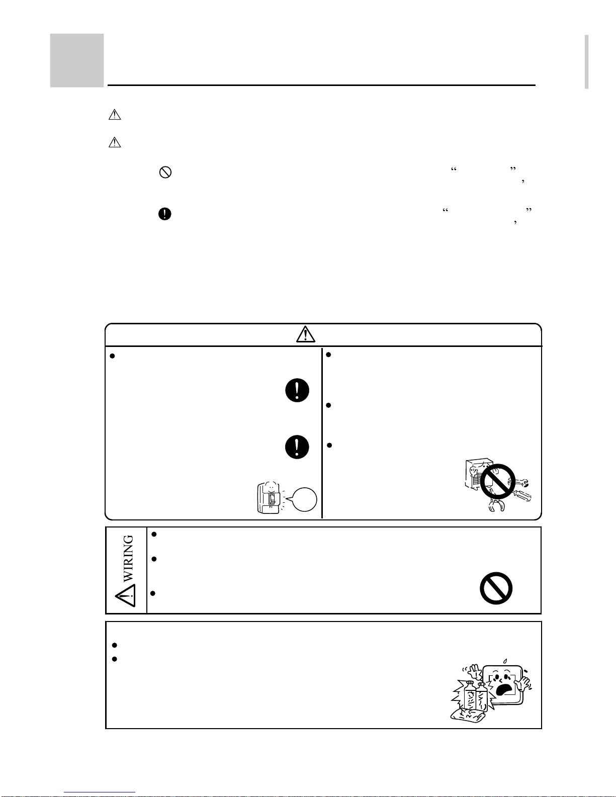
Below are four kinds of safety precautions and suggestions:
WARNING:
Improper use may result in severe consequences of death or serious
injures.
Improper use may result in injures or machine damages; in some
cases may cause serious consequences
CAUTION:
: It must be strictly prohibited where marked with Prohibited ,
otherwise may result in machine damages or endanger the user
personal safety.
: It must be strictly followed where marked with To be followed ,
otherwise may result in machine damages or endanger the user
personal safety.
Instructions: This information can ensure correct operation of the machine.
Be sure to follow the following important safety precautions.
These precautions should be at hand to be checked at any time when needed.
If air conditioner is transferred to a new user, this manual should be as well
transferred to the new user.
WARNING
Entrusting Installation
Installation should be entrusted to after
service staff; self-installation
may result in electric shock, fire
and the similar because of improper
installation.
If any abnormal phenomena are found
(e.g. smell of burning),
please stop running and cut off
power supply, and contact after service
staff to find out treatment method.
If keep using under this
situation, may result in
accident of electric and fire.
Power
of f
When intend to move and reset controller,
ask after service staff for responsibility.
Improper installation may result in electric
shock and fire.
Absolutely not to alter without authorization.
Improper alteration may result in accident
of electric shock, fire and the similar.
When repair needed, ask after service staff
to handle it.
Improper maintenance and
repair may result in electric
shock and fire.
Not be allowed to spray flammable spraying agent directly to controller.
Otherwise may result in fire.
Not be allowed to operate switch with damp hands, and not to spray controller
with water.
Otherwise may result in electric shock.
Not be allowed to press switch with matter having sharp tip.
Otherwise may result in malfunction or electric shock.
Maintenance
When maintenance or abnormity appeared, be sure to cut off manual operation power.
It will cause color change or paint-fading if wipe appearance of operation
portion with gasoline, thinner or chemical wiping cloth; be careful.
If operation portion is heavily soiled, shall immerse cloth in diluted
neutral detergent, and wipe that portion after wring the cloth, and wipe
cleanly with dry cloth.
Page 3

2
Brief description on functions
The remote central controller (hereunder as central controller ) is a necessary part at the option of the user for Haier commercial air conditioner remote
monitoring system group control functional network . A remote control monitor(or dector) is used to transform standard digital interface and realize bus code address communication.Connecting the air conditioner directly,it undertakes
local processing and gathering of air conditioner control and operation information,transmitting control and information data to the central controller.A network air conditioner (hereunder as air conditioner ) is defined as an air conditioner having an indoor computer board with remote control interface, only which
could combine with parts such as the monitors and central controller to form a
remote monitoring system
group control network , fulfilling the function of
data exchange and monitoring .
The central controller could consult through the monitors as well as display
through the LCD the main work status of the air conditioner. With it the work
status of main functions of the air conditioner could be set through key input
and LCD display . It can also monitor the basic working status of all air
conditioners in the network . In addition, the central controller is equipped with
a 24 hours real-time clock system for centrally control the clocks in the network .
Brief descriptions are given as follows :
1. Communication function
Communicate with the monitors in the group control network
To communicate with the monitors through the RS-485 bus (A, B). The
central controller sends commands to and receives response from the monitor;
communication by address enables sending and receiving control information,
work information and fault information between the monitors and the central
controller.
2. LCD display function:
The LCD could display the fundamental status of air conditioning units (are
the units existing? On/off? Fault? Are units group selected? Cursor and the
current unit no.);
The LCD can display the working status of the air conditioning unit with the
current number (mode, fan speed, temperature setting, room temperature,timer,
error code, central/remote control status);
The working status of the central controller (monitor/set status, panel locking
status, signaling status).
3. Key input function:
The keys for moving the current unit number cursor and for group selection:
, ,
, , SELECT;
The keys for setting working status of the air conditioning unit and control
conditions: ON/OFF, MODE, FAN SPEED, TEMP TIME
/
, CLOCK,
TIMER, CENTRAL/REMOTE, SET;
The key for locking key function of the central controller: LOCK.
4. Unit number setting function:
To enrich the control functions of Haier commercial air conditioner remote monitoring system, multiple controllers could be set to work together for a combination
of multiple functions. For this, the central controller is provided with a two-digital
switch for setting controller address.
Page 4

3
(Fig.2)
(Fig.1)
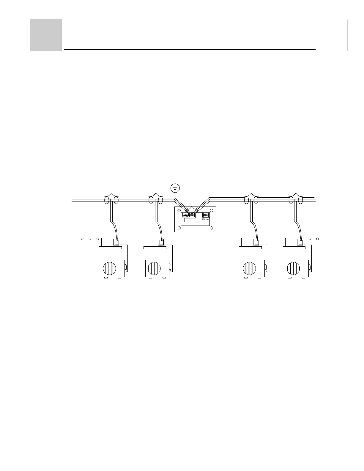
System general information
1. Realizing group control function with the central controller
A monitor is connected with an air conditioner through A+, A- of the 4-wire screw
terminals on the interface for air conditioner, meanwhile the monitor dial switch
shall be set as single unit working mode and the address unit number shall be set
according to the planed scheme, see "Setting of the Dial Switch" for detailed setting
and corresponding addresses. For realizing group control function through the
central controller, the system still needs to connect the monitors. Each monitor shall
be connected with the twin twisted shielded communicating bus through the twowire screw terminals (A, B) on the RS-485 interface. For the communicating bus, it
is required to be shield grounded and the resistances on two sides shall be matched.
2.Realizing double unit switch-over group control function with the central
controller
A monitor is connected with two air conditioners with the same model through the
4-wire screw terminals on the interface for air conditioner, meanwhile the monitor
dial switch shall be set as double unit switch-over working mode with the default
switch-over time of 24 hours, and the address unit number shall be set according to
the planed scheme, see Setting of the Dial Switch
for detailed setting and corresponding addresses. For realizing double unit switch-over group control function
through the central controller, the system still needs to connect the monitors. Each
monitor shall be connected with the twin twisted shielded communicating bus
through the two-wire screw terminals (A, B) on the RS-485 interface. For the communicating bus, it is required to be shield grounded and the resistances on two sides
shall be matched.
RS-485 bus Upper A Lower B
Rear view of the
central controller
View of the monitor
interface
Power cord
Power on/off
Indoor unit
Outdoor unit
A RS-485 B
RS-485 bus Upper A Lower B
Page 5
4
Installation and debugging
(Fig.3)
3. For some newly-developed models, such as A******BEA, A******BIA,
A******ERA, in indoor PCB , we set the stanard connector data transforma-
tion function of the detector. They can connect the central controller directly
through the RS-485 communication protocol. The detailed information
refers to the operation manual with the unit.
For the above models, have no double unitswitch-over group control function.
If you want the timing function, the weekly timer YCS-A001 is necessary,
and is used together with YCZ-A001. The address seeting of weekly timer
needs to be adjusted, please refer to the operation manual with the unit.
The detailed information refers to the operation manual with the unit.
RS-485 bus Upper A Lower B
Rear view of the
central controller
Indoor unit
Outdoor unit
RS-485
Page 6

5
(Fig.4)
Installation manual for wire controller
The communication wiring is 4 meter long; if the actual length is more
than it, please distribute wiring according to below table:
2. Communication wiring:
The wired controller is equipped with special communication wiring in the accessories.
3-core terminal (Polar wire) is connected with the terminal A, B, C of wired controller
respectively.
1. Wiring connections of wired controller:
There are three methods to connection wired controller and the indoor units:
A.One wired controller can control max. up to 16 sets of indoor units, and 3 pieces of
polar wire must connect the wired controller and the master unit (the indoor unit
connected with wired controller directly), the others connect with the master unit through
2 pieces of polar wire.
B. One wired controller controls one indoor unit, and the indoor unit connects with
the wired controller through 3 pieces of polar wire.
C. Two wired controllers control one indoor unit. The wired controller connected with
indoor unit is called master one, the other is called slave one. Master wired controller
and indoor unit; master and slave wired controllers are all connected through 3 pieces
of polar wire.
*One side of the shielded sheet of communication wire must be earthed.
Communication wiring length(m) Dimensions of wiring
< 100 0.3mm2x3-core shielded wire
100 and <200 0.5mm2x3-core shielded wire
A B C
Wired controller
Control wiring of wired
controller, polar.
1 2 3
1 2 3 1 2 3
1 2 3
1 2 3
Indoor 16Indoor 15Indoor NIndoor 2Indoor 1
Wired controller Wired controller Wired controller Wired controller Wired controller
(master unit)
1 2 3
Indoor 1
Wired controller
A B C
Wired controller
Polar wire
1 2 3
Indoor 1
Wired controller
A B C
Wired controller
Polar wire
A B C
Wired controller
Polar wire
A
B
C
Page 7

Cut off Cut oonnected
SW0-1 Master unit Slave unit
Note
6
Installation manual for wire controller
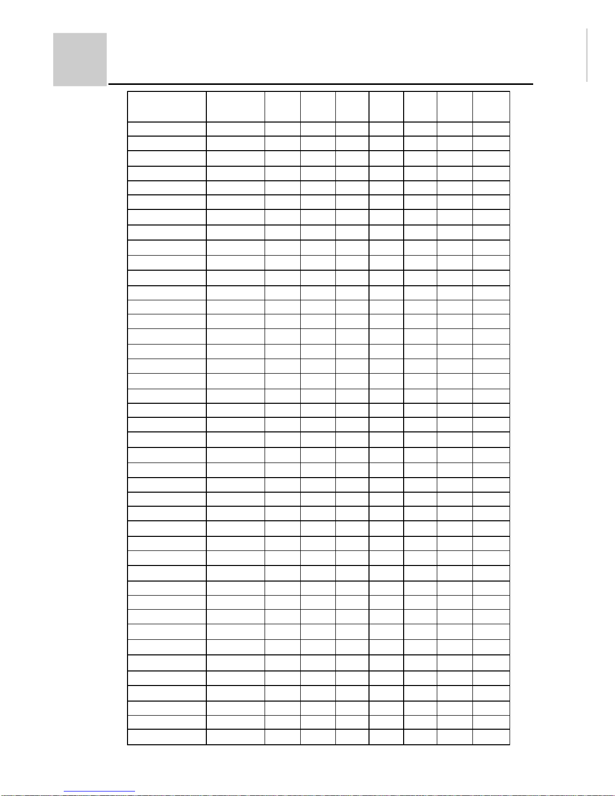
3.Setting address method:
The dip switch of indoor unit usually marked with "SW" or "BM", you can refer the
below table to set address:
If you use central controller , the clip switch will be used simultaneously.
Wiring request in central control type: port A-B is connected with indoor port refer to
A-B through 2-core shield wire. Requirements:
1.Port A connects with port A of all indoor units.
2.Port B connects with port B of all indoor units.
Refer to the Figure 3 to wiring.
The address setting can be realized by the dip switch, which used to set address in
indoor PCB. Please refer the indoor unit circuit diagram to find the dip switch.
If you use the group control function, there should be a master unit and 15 sets of
slave units.Refer to the operation manual with the unit to set the master unit or the slave
units.
The indoor PCB is matched with this wired controller (YR-E12)which can be set
according to below table:
When the wired controller controls several indoor units, there is only one Master unit,
and other can be set as Slave unit.
The detailed information manual with the unit to set the master unit or the slave units.
The wired controller must be used with cooperation with indoor unit. When wired control
type is selected, the function of indoor unit must be adjusted (after power cut off).
Indoor unit address
1
2
3
4
5
6
7
8
9
10
11
12
13
14
15
16
SW1-4
OFF
OFF
OFF
OFF
OFF
OFF
OFF
OFF
ON
ON
ON
ON
ON
ON
ON
ON
SW1-3
OFF
OFF
OFF
OFF
ON
ON
ON
ON
OFF
OFF
OFF
OFF
ON
ON
ON
ON
SW1-2
OFF
OFF
ON
ON
OFF
OFF
ON
ON
OFF
OFF
ON
ON
OFF
OFF
ON
ON
SW1-1
OFF
ON
OFF
ON
OFF
ON
OFF
ON
OFF
ON
OFF
ON
OFF
ON
OFF
ON
Page 8
7
Installation manual for wire controller
Address on central
controller
1
2
3
4
5
6
7
8
9
10
11
12
13
14
15
16
17
18
19
20
21
22
23
24
25
26
27
28
29
30
31
32
33
34
35
36
37
38
39
40
41
42
Indoor unit
address
1
2
3
4
5
6
7
8
9
10
11
12
13
14
15
16
--------
--------
--------
--------
--------
--------
--------
--------
--------
--------
--------
--------
--------
--------
--------
--------
--------
--------
--------
--------
--------
--------
--------
--------
--------
--------
SW2-3
OFF
OFF
OFF
OFF
OFF
OFF
OFF
OFF
OFF
OFF
OFF
OFF
OFF
OFF
OFF
OFF
OFF
OFF
OFF
OFF
OFF
OFF
OFF
OFF
OFF
OFF
OFF
OFF
OFF
OFF
OFF
OFF
OFF
OFF
OFF
OFF
OFF
OFF
OFF
OFF
OFF
OFF
SW2-2
OFF
OFF
OFF
OFF
OFF
OFF
OFF
OFF
OFF
OFF
OFF
OFF
OFF
OFF
OFF
OFF
OFF
OFF
OFF
OFF
OFF
OFF
OFF
OFF
OFF
OFF
OFF
OFF
OFF
OFF
OFF
OFF
ON
ON
ON
ON
ON
ON
ON
ON
ON
ON
SW2-1
OFF
OFF
OFF
OFF
OFF
OFF
OFF
OFF
OFF
OFF
OFF
OFF
OFF
OFF
OFF
OFF
ON
ON
ON
ON
ON
ON
ON
ON
ON
ON
ON
ON
ON
ON
ON
ON
OFF
OFF
OFF
OFF
OFF
OFF
OFF
OFF
OFF
OFF
SW1-4
OFF
OFF
OFF
OFF
OFF
OFF
OFF
OFF
ON
ON
ON
ON
ON
ON
ON
ON
OFF
OFF
OFF
OFF
OFF
OFF
OFF
OFF
ON
ON
ON
ON
ON
ON
ON
ON
OFF
OFF
OFF
OFF
OFF
OFF
OFF
OFF
ON
ON
SW1-3
OFF
OFF
OFF
OFF
ON
ON
ON
ON
OFF
OFF
OFF
OFF
ON
ON
ON
ON
OFF
OFF
OFF
OFF
ON
ON
ON
ON
OFF
OFF
OFF
OFF
ON
ON
ON
ON
OFF
OFF
OFF
OFF
ON
ON
ON
ON
OFF
OFF
SW1-2
OFF
OFF
ON
ON
OFF
OFF
ON
ON
OFF
OFF
ON
ON
OFF
OFF
ON
ON
OFF
OFF
ON
ON
OFF
OFF
ON
ON
OFF
OFF
ON
ON
OFF
OFF
ON
ON
OFF
OFF
ON
ON
OFF
OFF
ON
ON
OFF
OFF
SW1-1
OFF
ON
OFF
ON
OFF
ON
OFF
ON
OFF
ON
OFF
ON
OFF
ON
OFF
ON
OFF
ON
OFF
ON
OFF
ON
OFF
ON
OFF
ON
OFF
ON
OFF
ON
OFF
ON
OFF
ON
OFF
ON
OFF
ON
OFF
ON
OFF
ON
Page 9

8
Installation manual for wire controller
SW2-1
OFF
OFF
OFF
OFF
OFF
OFF
ON
ON
ON
ON
ON
ON
ON
ON
ON
ON
ON
ON
ON
ON
ON
ON
OFF
OFF
OFF
OFF
OFF
OFF
OFF
OFF
OFF
OFF
OFF
OFF
OFF
OFF
OFF
OFF
ON
ON
ON
ON
ON
SW1-4
ON
ON
ON
ON
ON
ON
OFF
OFF
OFF
OFF
OFF
OFF
OFF
OFF
ON
ON
ON
ON
ON
ON
ON
ON
OFF
OFF
OFF
OFF
OFF
OFF
OFF
OFF
ON
ON
ON
ON
ON
ON
ON
ON
OFF
OFF
OFF
OFF
OFF
SW1-1
OFF
ON
OFF
ON
OFF
ON
OFF
ON
OFF
ON
OFF
ON
OFF
ON
OFF
ON
OFF
ON
OFF
ON
OFF
ON
OFF
ON
OFF
ON
OFF
ON
OFF
ON
OFF
ON
OFF
ON
OFF
ON
OFF
ON
OFF
ON
OFF
ON
OFF
Address on central
controller
43
44
45
46
47
48
49
50
51
52
53
54
55
56
57
58
59
60
61
62
63
64
65
66
67
68
69
70
71
72
73
74
75
76
77
78
79
80
81
82
83
84
85
Indoor unit
address
--------
--------
--------
--------
--------
--------
--------
--------
--------
--------
--------
--------
--------
--------
--------
--------
--------
--------
--------
--------
--------
--------
--------
--------
--------
--------
--------
--------
--------
--------
--------
--------
--------
--------
--------
--------
--------
--------
--------
--------
--------
--------
--------
SW2-3
OFF
OFF
OFF
OFF
OFF
OFF
OFF
OFF
OFF
OFF
OFF
OFF
OFF
OFF
OFF
OFF
OFF
OFF
OFF
OFF
OFF
OFF
ON
ON
ON
ON
ON
ON
ON
ON
ON
ON
ON
ON
ON
ON
ON
ON
ON
ON
ON
ON
ON
SW2-2
ON
ON
ON
ON
ON
ON
ON
ON
ON
ON
ON
ON
ON
ON
ON
ON
ON
ON
ON
ON
ON
ON
OFF
OFF
OFF
OFF
OFF
OFF
OFF
OFF
OFF
OFF
OFF
OFF
OFF
OFF
OFF
OFF
OFF
OFF
OFF
OFF
OFF
SW1-3
OFF
OFF
ON
ON
ON
ON
OFF
OFF
OFF
OFF
ON
ON
ON
ON
OFF
OFF
OFF
OFF
ON
ON
ON
ON
OFF
OFF
OFF
OFF
ON
ON
ON
ON
OFF
OFF
OFF
OFF
ON
ON
ON
ON
OFF
OFF
OFF
OFF
ON
SW1-2
ON
ON
OFF
OFF
ON
ON
OFF
OFF
ON
ON
OFF
OFF
ON
ON
OFF
OFF
ON
ON
OFF
OFF
ON
ON
OFF
OFF
ON
ON
OFF
OFF
ON
ON
OFF
OFF
ON
ON
OFF
OFF
ON
ON
OFF
OFF
ON
ON
OFF
Page 10

9
Installation manual for wire controller
Address on central
controller
86
87
88
89
90
91
92
93
94
95
96
97
98
99
100
101
102
103
104
105
106
107
108
109
110
111
112
113
114
115
116
117
118
119
120
121
122
123
124
125
126
127
128
Indoor unit
address
--------
--------
--------
--------
--------
--------
--------
--------
--------
--------
--------
--------
--------
--------
--------
--------
--------
--------
--------
--------
--------
--------
--------
--------
--------
--------
--------
--------
--------
--------
--------
--------
--------
--------
--------
--------
--------
--------
--------
--------
--------
--------
--------
SW2-3
ON
ON
ON
ON
ON
ON
ON
ON
ON
ON
ON
ON
ON
ON
ON
ON
ON
ON
ON
ON
ON
ON
ON
ON
ON
ON
ON
ON
ON
ON
ON
ON
ON
ON
ON
ON
ON
ON
ON
ON
ON
ON
ON
SW2-2
OFF
OFF
OFF
OFF
OFF
OFF
OFF
OFF
OFF
OFF
OFF
ON
ON
ON
ON
ON
ON
ON
ON
ON
ON
ON
ON
ON
ON
ON
ON
ON
ON
ON
ON
ON
ON
ON
ON
ON
ON
ON
ON
ON
ON
ON
ON
SW1-3
ON
ON
ON
OFF
OFF
OFF
OFF
ON
ON
ON
ON
OFF
OFF
OFF
OFF
ON
ON
ON
ON
OFF
OFF
OFF
OFF
ON
ON
ON
ON
OFF
OFF
OFF
OFF
ON
ON
ON
ON
OFF
OFF
OFF
OFF
ON
ON
ON
ON
SW1-2
OFF
ON
ON
OFF
OFF
ON
ON
OFF
OFF
ON
ON
OFF
OFF
ON
ON
OFF
OFF
ON
ON
OFF
OFF
ON
ON
OFF
OFF
ON
ON
OFF
OFF
ON
ON
OFF
OFF
ON
ON
OFF
OFF
ON
ON
OFF
OFF
ON
ON
SW1-1
ON
OFF
ON
OFF
ON
OFF
ON
OFF
ON
OFF
ON
OFF
ON
OFF
ON
OFF
ON
OFF
ON
OFF
ON
OFF
ON
OFF
ON
OFF
ON
OFF
ON
OFF
ON
OFF
ON
OFF
ON
OFF
ON
OFF
ON
OFF
ON
OFF
ON
SW2-1
ON
ON
ON
ON
ON
ON
ON
ON
ON
ON
ON
OFF
OFF
OFF
OFF
OFF
OFF
OFF
OFF
OFF
OFF
OFF
OFF
OFF
OFF
OFF
OFF
ON
ON
ON
ON
ON
ON
ON
ON
ON
ON
ON
ON
ON
ON
ON
ON
SW1-4
OFF
OFF
OFF
ON
ON
ON
ON
ON
ON
ON
ON
OFF
OFF
OFF
OFF
OFF
OFF
OFF
OFF
ON
ON
ON
ON
ON
ON
ON
ON
OFF
OFF
OFF
OFF
OFF
OFF
OFF
OFF
ON
ON
ON
ON
ON
ON
ON
ON
Page 11

10
180mm
(Fig.5)
MONI TOR
SET
UNIT
AUTO
TEMP
ROOM
TEMP
CENTRAL
REMOTE
TIMER ON
EVERY DAY
SELECT
ON
OFF
MODE
TEMP.
TI ME
TI ME TI MER
CENTRAL
REMOTE
CONFIRM
LOCK
TIMER OFF
(Fig.6)
FAN SPEED
Outside view and dimensions of the central
controller
As illustrated:
(Figure 5 is the front view and Figure 6
is the side view) The central controller
is 180mm long, 120mm wide and 64.4 mm
thick.
64. 4mm
Total on/Total off
Page 12

11
MONI T0R
SET
UNIT
AUTO
TEMP
ROOM
TEMP
CENTRAL
REMOTE
TIMER ON
EVERY DAY
SELECT
ON
OFF
MODE
TEMP.
TIME
TIME TI MER
CENTRAL
REMOTE
CONFIRM
LOCK
TIMER OFF
FAN SPEED
Description and function of keys on the
controller
Display of operation mode
and signal emitting
LOCK display
Display of current unit number
Location of the indicating cursor
Display of MONITOR/SET
Generally indicating MONITOR . When
setting ON/OFF or other items, it changes
from MONITOR
into SET .
Display of the connected units
Flashing
indicates the cursor for current unit
or that the monitor and air conditioner are in
group selection status.
Lighted
indicates the monitor for the unit
has been linked into the network, otherwise not
linked.
Lighted
indicates the unit is in "on" mode, otherwise in
"off" mode.
Flashing
indicates fault.
Flashing
of the current unit
indicates the cursor, flashing
of non-current unit indicates the
unit is in group selection status.
Direction keys
Up
Down
Left
Right
Used to select the current unit
number
SELECT key
To determine the selected unit
number during group selection,
the
of the corresponding
unit number flashes at the same
time.
LOCK key
This key can be used to lock the
keys and LCD display.
ON/OFF key
Used to select unit on/off.
MODE key
Used to select running mode.
Display of fan speed and
louver
Total on/ Total off indicator
Total on/ Total off key
Display of temperature setting
FAN SPEED key
To select the fan speed.
Note: 1 In MONI
mode, pressing SEL, MODE, FAN SPEED, TEMP TIME keys
may change the MONITOR
mode into SET
mode. If SET
key or other keys
hasn t been pressed within 10s, it will automatically return to MONI
mode.
2 The button with blue background button film can send the control command.
3 The response condition of the Mode button, TEMP betton and FAN SPEED button is
that the unit is at ON state.
TEMP/TIME keys
Used to set a desired room
temperature, clock and time.
CLOCK key
Used to unitarily set the clock.
TIMER key
To select timer mode:
TIMER ON/TIMER OFF
/blank
CONFIRM key
Used to confirm the function
settings and send to the air
conditioner corresponding to
the selected unit number.
CENTRAL/
REMOTE key
To select central
or remote control
method.
Display of
self-check code
Display of time setting
Display of CENT/REM
Display of room
temperature
Total on/Total off
Page 13

12
TEMP
REMOTE
UNI T
ROOM
TEMP
SELECT
ON
OFF
MODE
TEMP.
TI ME
TI ME TI MER
CENTRAL
REMOTE
CONFIRM
LOCK
FAN SPEED
Operational guide
Total on and Total off
Pressing the Total on and Total off
key could turn on or off all connected indoor
units.
1. Press the Total on and Total off
key to send all on/all off instruction.
There is indication for signaling and the working status changes.
In all on status, pressing this key could turn all indoor units off and the
indicator turns off.
In all off status, pressing this key could get all indoor units entering on
and operation mode, and the indicator turns on.
Note:
1. After a single unit is turned on, this key enters all on mode, led is on.
2. The default operation mode is AUTO mode. If the remote control
monitor connecting with the air conditioner hasn t power failure
resumption function, the air conditioner will operate in the mode
memorized by the remote control monitor.
3. Total ON/OFF function: the air conditioner will make time-delay
control in turns, in the precess, the current air conditioner state
information may be flash, but it is normal.
Total on/Total off
MONI TOR
1
Page 14

13
SET
UNI T
TEMP
ROOM
TEMP
REMOTE
SELECT
ON
OFF
MODE
TEMP.
TI ME
TI ME TI MER
CENTRAL
REMOTE
CONFI RM
LOCK
FAN SPEED
Operational guide
Unit selection and group
selection control
The central controller provides three control modes:
1.Unitary control mode: See Total on/Total off Unitarily Control Function .
2.Unit selection control mode:
1 The cursor flashes at
of the current unit. Using the direction keys
may change the flashing location of the cursor and the current
unit number (the cursor will flash even if the unit does not exist.). The
controller takes the current unit with the flashing cursor as unit selection
mode;
2 After completion of selection, parameters of mode, fan speed, temperature
and timer could be changed;
3 After setting the parameters, press CONFIRM
key to send the settings
to the air conditioner and thus the unit selection control is completed.
4 After step , directly press the ON/OFF
key and CENTRAL/REMOTE
key, the requirement settings could also be transmitted to the air conditioner
and then the unit selection control is completed.
Within 10s if no parameter (mode, fan speed, temperature) setting keys
haven t be pressed or the CONFIRM
key hasn t be pressed to send instruction
to the air conditioner, the time-out control will automatically cancel the
just made settings, and the system will automatically restore central control
and cyclic monitor status.
Remarks:
Total on/Total off
4
3
2
2
2
Page 15

14
SET
UNI T
TEMP
ROOM
TEMP
REMOTE
SELECT
ON
OFF
MODE
TEMP.
TI ME
TI ME TI MER
CENTRAL
REMOTE
CONFI RM
LOCK
FAN SPEED
Operational guide
Unit selection and group
selection control
3.Group selection control mode:
1 Move the cursor to the unit to be group selected and press SELECT
key
to enter group selection mode. Then use the
keys to move the
cursor to the next unit number to be selected and press SELECT
key again.
Repeat until selection is completed. After group selection is fulfilled, set
the working status of the central controller;
Keep the cursor at a unit already group selected and press SELECT
key
again,the original selection will be canceled; afterwards the current unit
display condition will not change because the cursor keep flashing, whereas
after removing the cursor you ll find the result of group selection or canceling
of group selection;
2 After completion of selection, parameters of mode, fan speed, temperature
and timer etc. could be changed;
3 After parameter setting, press SET
key sending the desired settings to the
air conditioner and thus the group selection control is completed.
4 After step , directly press the ON/OFF
key and CENTRAL/REMOTE
key, therequirement settings could also be transmitted to the air conditioner
and then the group selection control is completed.
Remarks
:
1.Within 10s if no parameter (mode, fan speed, temperature) setting keys
haven t be pressed or the CONFIRM
key hasn t be pressed to send
instruction to the air conditioner, the time-out control will automatically
cancel the just made settings, and the system will automatically restore
central control and cyclic monitor status.
2.During group selection, the first selected air conditioner will be defined as
the first unit, which will be taken as the control reference, i.e. if no mode
has been set, after pressing CONFIRM
key, all air conditioners under
group selection control will operate in the same mode as that of the first
air conditioner.
Total on/Total off
4
2
2
2
Page 16

15
UNI T
TEMP
ROOM
TEMP
REMOTE
SELECT
ON
OFF
MODE
TEMP.
TI ME
TI ME TI MER
CENTRAL
REMOTE
CONFIRM
LOCK
FAN SPEED
Operational guide
Turn on/turn off
Using the ON/OFF key:
1.Carry out unit selection or group selection to select the units to be controlled;
Press ON/OFF
key to send control orders;
2.If the units are in on status before unit or group selection, pressing this key
will send turning off order to get units stop;
3.If the units are in off status before unit or group selection, pressing this key
will send turning on order to get units start.
MONI TOR
Total on/Total off
Page 17

16
Operational guide
AUTO, COOL, DRY, HEAT,
FAN SPEED, TEMP, CLOCK
1. Conduct unit selection or group selection to select the units to be controlled.
2. Operation mode
Press MODE
key to select the operation mode. Each pressing will change
the working mode in the following sequence:
Select the working mode you desire.
3. Fan speed shift
Press FAN SPEED
key to select fan speed. Each pressing will change the fan
speed in the following sequence.
Select the desired fan speed.
AUTO
COOL
DRY
HEAT
AUTO
4.Temperature setting
Press TEMP TIME
key.
Each pressing will increase the temperature by 1
.
Each pressing will decrease the temperature by 1 .
The temperature could be set at your desire between 16
and 30 , which will
be displayed by the LCD.
Note: These keys will also be used in clock setting and timer setting. See the related
description for details.
5.Setting confirmation
In CONFIRM
mode, pressing CONFIRM
key to send control orders to air
conditioners, after which the central controller will change into cyclic monitoring
status.
Note: Within 10s if no parameter (mode, fan speed, temperature) setting keys haven t
be pressed or the CONFIRM
key hasn t be pressed to send instruction to the air
conditioner, the time-out control will automatically cancel the just made settings, and
the central controller will restore cyclic monitoring status.
SET
UNI T
TEMP
ROOM
TEMP
REMOTE
SELECT
ON
OFF
MODE
TEMP.
TIME
TIME
TIMER
CENTRAL
REMOTE
CONFIRM
LOCK
FAN SPEED
Total on/Total off
4
5
Page 18

17
UNI T
TEMP
ROOM
TEMP
REMOTE
SELECT
ON
OFF
MODE
TEMP.
TI ME
TI ME TI MER
CENTRAL
REMOTE
CONFIRM
LOCK
FAN SPEED
Operational guide
Clock setting
To adjust the settings and unify the system clocks
1. Press
Time
key
Each pressing of the TEMP TIME
key, the time setting will increase
by 1 min; keep pressing will increase the value rapidly.
Each pressing of the TEMP TIME
key, the time setting will decrease
by 1 min, keep pressing will decrease the value rapidly.
2. In CONFIRM
mode, press the CONFIRM
key to send control orders for
controlling the air conditioner central control system. After confirmation of
sending orders, the central controller will change to cyclic monitoring status.
1 Within 10s if the CONFIRM
key hasn t been pressed to confirm order
sending, the time-out control will automatically cancel the just made settings,
and the central controller will restore cyclic monitoring status.
2 The centrol controller will uniform the clock auto matically once every day.
Note:
Total on/Total off
SET
Page 19

18
Operational guide
Timer Function
UNI T
TEMP
ROOM
TEMP
REMOTE
SELECT
ON
OFF
MODE
TEMP.
TI ME
TI ME
TI MER
CENTRAL
RETOME
CONFI RM
LOCK
FAN SPEED
TIMER ON
Total on/Total off
EVERY DAY
TIMER OFF
MONI TOR
The timing function:
1. The timing set of central controller will be performal by the detector. Because
of the large time tolerance, we recommend that you use the weekly time
YCS-A001 to realise the daily management.
2. The central controller will set TIMER ON, and meanwhile the TIMER OFF
time will be 0 o'clock as default.
3. The central controller will set TIMER OFF, and meanwhile the TIMER ON
time will be 0 o'clock as default.
4.TIMER ON/OFF, TIMER ON and TIMER OFF- once being set, they will be
performed in turns every day.
5. If you want to cancel the timing function, when LCD screen displays TIMER
on and TIMER OFF are all 0 o'clock, press "SET/CONFIRM" button to cancel it.
6. Press TIMER buttom, LCD displays the following in turn: TIMER ON
TIMER OFF TIMER ON/OFF TIMER ON/OFF everyday TIMER
ON/OFF are 0 o'clock.
7. If you want to set timing function, select the TIMER ON clock and the
TIMER OFF clock, and then press "SET/CONFIRM".
8. After the power is off, the clock needs to be set again.
Page 20

19
SELECT
ON
OFF
MODE
TEMP.
TIME
TIME
TIMER
CENTRAL
REMOTE
CONFI RM
LOCK
UNI T
TEMP
ROOM
TEMP
REMOTE
SELECT
ON
OFF
MODE
TEMP.
TIME
TIME
TIMER
CENTRAL
REMOTE
CONFIRM
LOCK
UNI T
TEMP
ROOM
TEMP
REMOTE
FAN SPEED
FAN SPEED
Operational guide
Central/Remote setting, keypad locking,
setting confirmation and reset function
1.Central/remote setting function is applicable only
for those air conditioners with wire remote controller
or panel, but not for models with wireless remote
controller. It deals with management of air condi-
tioners inside the central control system. Once the
air conditioner has been set as central status, it
could be controlled only through the remote control
interface.
Carry out unit selection or group selection procedure to select the units to be
controlled.
Press CENTRAL/REMOTE
key.
If the unit is in remote mode before selection, pressing this key will send
orders getting the unit in central mode;
If the unit is in central mode before selection, pressing this key will send
orders enabling the unit in remote status.
In central status, the air conditioner does not accept instructions from the
wire controller but only those from the central controller; whereas in remote
mode, the air conditioner accepts orders from both the wire controller and the
central controller.
2.Locking, setting confirmation and reset function setting method
Central controller keypad locking:
This function is used to control if the keypad of
the central controller is valid, avoiding random
operation by unrelated persons.
Keep pressing LOCK
key until the key
symbol is displayed, which means the
keypad (other keys) is locked;
Keep pressing LOCK
key again for a while,
the key symbol disappears, it indicates the keypad could be regularly used;
CONFIRM
key:
It is used to confirm the settings of air conditioner running mode, fan speed,
temperature and timer. This key is invalid in monitor status.
Reset key:
It is installed inside the central controller for reset operation. In case the
central controller operation is invalid or dead for a long time (not including
over long control time, and self-locking of the keypad), press reset key to
restart the central controller. The location of the reset key is as shown in the
following figure:
Open the controller at the two clasps located at the top front side of the central
controller, then you can see the reset key as shown in the figure. Pressing this
key could restore the controller to normal conditions.
Total on/Total off
MONI TOR
Total on/Total off
MONI TOR
3. Master/Slave controller set:
When the central controller is powered on, the controller with the default
address FFH is the Master controller .
In the group control network, there's only one Master central controller. The
Slave controller will display " ", when being powered on, In the operation,
you can change over between Master controller and Slave controller by the
button. The setting of Master/Slave controller please refers to the address
setting section.
Page 21

20
1
2
3
4
5
6
7
8
9
10
11
12
13
14
15
16
17
18
19
20
21
22
23
24
25
26
27
28
29
30
31
Failure diagnosis
Upon abnormal operation:
Please read the User s Manual
attached with the indoor unit before asking for
repairing. You may contact the after-sales technicians after careful checkup.
When faults arise, the symbol
appears along with the error code.
The central controller faults corresponding to error codes are given in the
following list (including air conditioner faults and group control network faults):
Code
Meaning
None (normal operation)
Fault with indoor ambient temperature sensor
Fault with indoor tube temperature sensor
Indoor heating overload protection
Indoor cooling icing (overload) protection
Indoor & outdoor communication error
Communication fault between panel (wire controller) and indoor unit
(air conditioner indication, central controller shows 30)
Module fault (PFC protection
DC)
No load
Compressor overheating
Abnormal CT current
Fault with outdoor ambient temperature sensor
Fault with outdoor heat exchanger (tube temperature) sensor
Protection of supply overvoltage or undervoltage
High voltage protection
--- Fault with outdoor evaporator sensor
--- Cooling overload
EEPROM fault
Fault with outdoor return gas sensor
Fault with compressor sensor
--- Fault with indoor evaporator sensor
Drain system failure
Power supply 3-phase fault (phase lack or mistake)
Humidity sensor malfunction
Indoor fan failure (fan overcurernt, fan IPM protection, fan Holtz .
element fault)
Blank
Low voltage protection
--- Electronic expansion valve failure
--- Dust remover screen needs cleaning
Insufficient refrigerant
Abnormal communication between monitor and air conditioner or exterior alarm
input singal.
Abnormal communication between monitor and bus or temperature cut off abnormal.
Outdoor fan failure (fan overcurernt, fan IPM protection, fan Holtz
.
element fault)
Page 22

21
1PH , 220-240V~, 50Hz
91. 5mm
Installation procedure
1. Wire connecting
A B
Power supply
To connect the process
control monitor/detector
2. Installation method
A wiring box cover must be used.
The central controller shall be installed into the installation box built in the
wall fastening with 4 screws (as shown).
Rear view
Note: Please confirm the supply voltage of AC220-240V and correct wiring. In
application environment with intense electromagnetic interference, the central
controller should be shielded, while the connecting wire between the monitor
and the central controller should be shielded twin twisted wire.
Page 23

Installation and debugging
22
1. It must form a complete set of documents (project layout for group control
net, installation and construction records for group control net, debugging
records for group control net, maintenance and repair records for group
control net) for group control net of Haier commercial air conditioner long
distance system (hereinafter for short as: group control net) from layout
design, installation, debugging to after service, and file all for future
reference.
2. Layout design of group control net shall be finished in advance, including:
(1) compositions of group control net system and quantities controlled;
(2) selection type of air conditioner, installation place, power distribution and
wiring manner and connection to detector;
(3) installation place of detector, allocation of unit address code, power distri-
bution and wiring manner and connection to group control bus;
(4) installation and wiring of group control bus, length limitation of bus,
resistance matching of two ends of bus, and single point earth of bus shield-
ing layer;
(5) installation place of central controller, allocation of unit address code, power
distribution and wiring manner.
3. Principles of layout design of group control net:
(1) detector is essential part, to keep proper responding speed and communication
reliability, detector quantities carried by one central controller shall not more
than 64;
(2) air conditioner must be a net air conditioner, installation must strictly follow
the installation and operation instructions shipped with the unit, and confirm
that power blackout compensation function of local air conditioner has been
cancelled when debugging;
(3) suggest that do not use two-unit switchover function of detector in the case
of high load, i.e. suggest that do not use one detector to load two air condi-
tioners when detector forming group control net, otherwise temperature
difference control may be affected. If it is necessary to install two-unit switch-
over function for group control net, air conditioners with same type and half
installation distance of that of normal installation are required;
(4) installation place of detector shall not too far away from air conditioner, not
exceed the wiring length;
(5) unit address code of detector shall be strictly allocated in a sequence from
small one to big one, and set continuous unit number;
(6) for power distribution of detector, the power distribution line and commu-
nication line shall not be too close from each other or in the same wiring
channel, and no other special requirements;
Page 24

23
Installation and debugging
close from each other or in the same wiring channel, and others may refer
to wiring requirements of building autocontrol system;
(10) limit the total length of group control bus to 1000 meters; optional due
to the site operation.
(11) at both ends between Bus A and Bus B connect a metallic membrane
precision resistance of 100ohm respectively;
(12) single point earth for bus shielding line, suggest to be arranged in the middle
of communication bus, close to central controller;
(13) in principle, installation place of central controller shall be arranged in the
middle of communication bus, close to shielding earth line of communi-
cation bus;
(14) unit address codes of central controller adopt the default settings;
(15) central controller has its own power distribution line, the power distribution
line and communication line shall not be too close from each other or in
the same wiring channel, and no other special requirements.
4. Installation and construction of wiring of group control net shall be processed
together with installation and debugging of net air conditioner, pay attention to
commissioning before installation.
5. Connection between detector and air conditioner: detector working mode and
unit address code shall be strictly set according to planned layout; detector
makes wire communication with at most two air conditioners (A, B) through
4-post screw-fixing terminal at air conditioner interface (A
+, A-
, B+, B-); con-
nection between detector and air conditioner use uniform wiring; use uniform
wiring for connection between detector and air conditioner, one plug in type
terminal of wiring connected to long distance control interface on the computer
board of air conditioner, and cores of another terminal respectively connected
to A+ and A- (B+ and B-); connection has polarity, and generally white wire
connected to A+/B+ and black/red wire connected to A-/B-; if detector cannot
work normally when debugging, then can check and remove malfunction by
changing positive and negative polarity. During debugging also can judge
whether communication interface to air conditioner is normal according to the
running status indicated by operation indicator (green LED).
(7) for connection between detector and group control bus, not allowed to
connect branch line from the group control bus;
(8) shielding line of communication line between detector and air conditioner
and the shielding line of communication bus between detector and central
controller shall be shorted;
(9) wiring and power distribution line of the group control bus shall not be too
Page 25

24
Installation and debugging
6. Connect detector and communication bus after finish the wiring of communi-
cation bus: connect several detectors to communication bus in parallel, all
terminal port A (including central controller) on one bus, and all terminal
port B (including central controller) on another bus, at both ends of the com-
munication bus - A terminal port line and B terminal port line shall paralleling
connect a metal membrane precision resistance of 100ohm respectively. Earth
one point of the shielding line of communication bus, which is at the middle
position of the communication bus, and the total length of communication bus
shall be limited within 1000m.
7. Connect central controller and communication bus after finish installation and
connection of detector: central controller is connected to communication bus
through the 2-post screw-fixing terminal (A and B) of interface RS-485,
locating in the middle of the communication bus, with position close to the
earth point of the shielding line of communication bus.
8. Power on and debugging: after power on, central controller periodically
monitors the detector and air conditioner groups on the communication bus,
and after inquiring for a period of time the unit number shall display as expected,
check and debug if having any difference.
9. Set the dialing switch of detector: OFF means 0 and ON means 1see the table
below for detail setting check list.
No.
1
2
3
4
D3 D4
0 0
0 1
1 0
1 1
Address
FFH
FEH
FDH
FCH
Bit 1 and 2 are pre-set.
Funct i on
Master
Sl ave
Sl ave
Sl ave
The default set when out of factory:
1.OFF 2. OFF 3.OFF 4. OFF
Page 26

25
1 - unit A signal groundwire
2 - unit A signal wire
3 - unit B signal groundwire
4 - unit B signal wire
5 - centralized controlling interface B
6 - centralized controlling interface A
7 - 12VDC power for the detector
8 - power indicator light(red),also as
fault indicator
9 - communicate indicator light(yellow)
10 - charactron,display setting address
and switching time between two units.
11 - run indicator light(green)
12 - installation hole
13 -binary switch,set single/double and baudrate
14 - keys,include:Inc,Dec,switch,enter,
emergency
YCJ-A002 sketch
air conditioner
interface
1
2 3
4
5
6
7
problem about the arranging of the connecting line
between air conditioner and its upper unit:
holes prepared for passing line behind the detector
can be used--for those installation project who have
already buried the pass line.To those who haven't
prepared pass line,the thinner part on the top of the
detector shell could be opened with tools for passing
line.
power
red yellow
green emergency
power
communicate
run
Double/Single
9600/1200
SMG
S1
S2
S3
S4
S5
INC
DEC
SWITCH ENTER
EMERGENCY
LED1red
LED2yellow
LED3green
8
9
10
11 12
13
14
+
-
YCJ-A002
open the
cover from
here
Model of monitor/detector
1. Remote control detector
2.Group control detector
57
B- B+ A- A+
B RS-485 A
RS- 232
138
57
Page 27

26
1PH AC220-240V 50Hz
3W
180X120X64.4mm
0.39kg
1.
Performance parameters and spare parts
Power supply
Power consumption
Maximum dimension
Weight
Spare parts
no
Note: The company focuses on technological innovation and reserves right to
modify the parameters without further notification.
2. User self-provided parts:
Performance parameters and spare parts
a. Power cord: copper core wire with the conductor diameter not less than
1.0mm2, the plug is not less than 5A250V.
b. Group control bus: Recommended type: UL2547 or equivalent model twin
twisted shielded wire, the specification not lower than AWG20 (UL2547-202).
c. Installation mechanical box for the central controller: 4 holes installation
location dimension: 91.5*86 bilaterally symmetric in the whole, vertically
symmetric with the upper variation of 2 (the hole is 15+ apart from the upper
edge and 19 apart from the lower edge). See the dimensions shown in the
figure on Page 15.
Page 28

This document was created with Win2PDF available at http://www.daneprairie.com.
The unregistered version of Win2PDF is for evaluation or non-commercial use only.
 Loading...