

Page 1
Manual of Weekly Timer
YCS-A001
Contents
Safety Precautions------------------------------------1-2
Function Introduction--------------------------------3-4
System Outline----------------------------------------5-8
Operation instruction--------------------------------9-12
Maintenance--------------------------------------------13
Appearance/Dimension/Interface--------------------14
Installation and Debugging------------------------14-17
Performance Parameter and Fittings-----------------18
User's Self-provide Parts ------------------------------18
Detector--------------------------------------------------19
Central Controller---------------------------------------20
No.0010573289
Please read this operation manual carefully before using the appliance.
Keep this manual in a safe place.
Page 2
Safety Precautions
The following lists four kinds of safety precautions and recommendations:
Warning:Improper use may cause death or serious injury, etc. serious
consequences.
Notice:Improper use may cause body injury or unit damage; in some cases,
it may cause serious consequences.
*
Any contents marked with this "Prohibition" symbol are the actions
must be prohibited. Otherwise, it may cause unit damage or
endanger the body safety of user.
Any contents marked with this "Force" symbol are the actions
*
must be force done. Otherwise, it may cause unit damage or
endanger the body safety of user.
The following safety precautions must be observed.
These safety precautions should be kept in hand to consult it when needs.
If the air conditioner is resold to a new customer, this manual also should be
given to him.
Warning
The installation work shall be done by a qualified person and what the
manual specified. If installation is not proper, water leakage, electric shock,
fire and other accidents will occur.
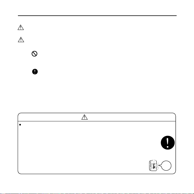
If finding abnormal phenomenon (e.g. smell of fire), please cut the
power immediately and contact our after-sale service staffs for the solvent.
In this case, if you still use the unit, it will be damaged and
electric shock or fire accident may be caused.
Power
off
1
Page 3
Safety Precautions
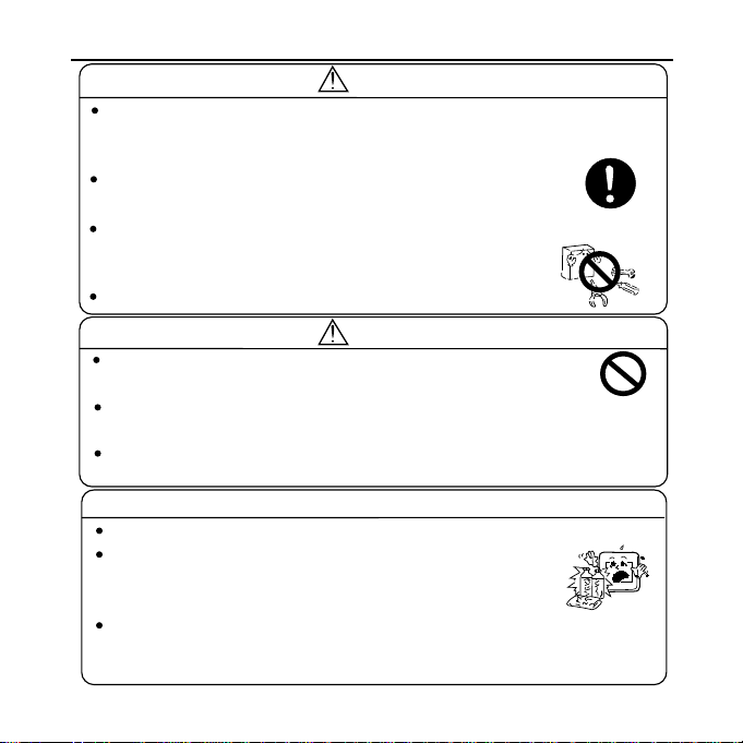
Warning
Please let the after-saleservice staffs do the job when the manual must
be removed, reseted. Imporper installation may cause water leakage,
electric shock and fire accident.
Do not alteration the manual by yourself, the improperty
alteration may cause electric shock and fire accident.
When needing repairing, please contact our after-saleservice staffs to
do it. Imporper repairing may cause electric
shock and fire accident.
The power supply : 220VAC
Notice
Do not put or use any flammable spray liquid near the
manual. Otherwise, electric shock may occur.
Do not operate the manual with wet hands. Do not
use water to clean the manual. Otherwise, electric shock may occur.
Do not press the manual and switch with acuminate object. Otherwise,
electric shock may occur.
Cleaning
Turn off the power supply switch before cleaning or abnormality occur
Do not use the thinner, benzine, or chemical dishcloth
cleaning the manual . Otherwise, discolourment or
coating desquamation may occur.
If it is very dirty, dissolve neutral deter gent in the lukewarm water and
make the colth wet with the water. After wiping, clean off the detergent
using clean water. Clean with soft and dry dishcloth.
2
Page 4
Function Introduction
The weekly timer is a special functional part for Haier Commercial Air Conditioner's remote
monitoring system-group control function network (hereinafter abbreviated as group control network)
and the user's optional part. Remote central controller (hereinafter abbreviated as central controller)
achieves the coding and display of control data by its keystroke and LCD screen; connected to
bus and executes the control to the air conditioner's basic functions by detector. Remote detector
(hereinafter abbreviated as detector) is used to transform the standard digital interface to realize
the communication of bus code sub-address; connected directly to air conditioner to execute local
operation and collection to the control information and working information of air conditioner and
to transmit the control and information data. Network air conditioner (hereinafter abbreviated as
air conditioner) means the air conditioner, which indoor PCB possesses remote control interface.
Only the network air conditioner can cooperate with detector, central controller and weekly timer,
etc. parts to form the remote monitoring system-group control network and fulfill data exchange
and monitoring function.
The function level of weekly timer and the central controller is the same. It can be checked
by detector and displayed by LCD screen the trouble state and timing setting of air conditioner. It
also can set the timing settings of the air conditioner within a week by keystroke input cooperating
with LCD display. Weekly timer can be either used together with central controller or used
independently (the detector is the essential part). Additionally, the weekly timer is equipped with
24-hour real-time clock system to unify the clocks in the group control network (the clocks in group
control network and air conditioner are respectively independent and do not interfere with each
other). The brief introductions are as follows:
1.Communication Function
PROGRAM
NO.
1 2 3 4 5 6 7
SET 1 ON OFF
SET 2 ON OFF
1 2 3 4 5 6 7
NO.
Hour
Min.
Time
ON/OFF
Number
HolidayProgram
Cancel
Confirm
Week
3
Page 5

Function Introduction
Communication with the detector of the group control network.t
Executing communication with detector by RS-485 bus (A, B). The weekly timer sends
a control command and communicates according to unified address; the execution of
the command is delayed. The weekly timer can simultaneously monitors the trouble
information sent from detector.
2.LCD function:
The LCD can display the weekly timing settings of the air conditioner (7 days a
week and each day can set max two times of timer on and timer off),
The LCD can display the trouble code information of the air conditioner with trouble,The
LCD can display the current time of the clock and weekday's information,
The LCD can display holiday setting, which is used to temporarily cancel the On
function of the air conditioner.
3.Keystroke input function:
The keys used in normal state to adjust and confirm the clock and weekdaystime, Confirm, Cancel,
The key used for enter and quit from timing setting program state-program.
The keys used to switch programmed contents-Date, Hour, Minute.
The keys used to adjust the program contents-- ,
The keys used to whether accept the programmed contents or not-tConfirm, Cancel.
The key used in normal state to temporarily cancel the special date timing functionHoliday.
4.Unit number setting function:
In order to rich the control function of Haier Commercial Air Conditioner's remote
monitoring system and be able to set multiple controllers combined use to fulfill the
combination of multiple functions, the weekly timer is configured with two dial-code
switches used to set the controller's addresses (the controller's addresses cannot be
repeated in the same control network).
4
Page 6
System Outline
The weekly timer has its independent own power supply. Its communication interface
is RS-485 interface, and the two-core screw fixed terminals (A, B) is connected with
shielded twisted pair communication bus and set the address number different from those
of other controllers.
1. Use weekly timer to realize weekly timing function:
The detector is connected with one air conditioner by the 4-core screw fixed terminals
A+ and A- of air conditioner interface, then accordingly set the dial-code switch of the
detector in single unit working mode; the address number setting shall be performed
according the planned program, for specific setting and corresponding address, please
refer to the dial-code switch setting in detector's operation manual; use weekly timer to
fulfill weekly timing function, the system needs to be connected with weekly timer; each
detector and weekly timer is connected with shielded twisted pair communication bus
by the 2-core screw fixed terminals (A and B) of its RS-485 interface; the communication
bus must be shielded and grounded, and the resistors in its two ends shall be suited.
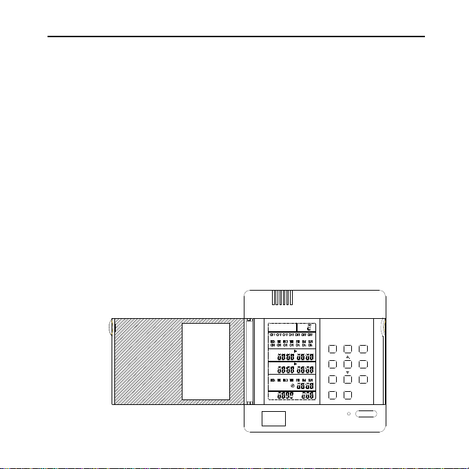
View of the instrumentation
Resetting
Indoor unit
Outdoor unit
interface
Air Conditoner HMI
PROGRAM
1 2 3 4 5 6 7
SET 1 ON OFF
SET 2 ON OFF
1 2 3 4 5 6 7
NO.
NO.
Number
HolidayProgram
Hour
Cancel
Min.
Confirm
Week
Time
ON/OFF
Power cord
Power on/off
5
Page 7
System Outline
2. Use weekly timer to realize two units auto-changeover function:
The detector is connected with two same model air conditioners by the 4-core
screw fixed terminals of air conditioner interface; then accordingly set the dial-code
switch of the detector in double units working mode, and the double units switch time
is default 24 hours; the address number setting shall be performed according the planned
program, for specific setting and corresponding address, please refer to the dial-code
switch setting in detector's operation manual; use weekly timer to fulfill double units
switch weekly timing function, the system needs to be connected with weekly timer;
each detector and weekly timer is connected with shielded twisted pair communication
bus by the 2-core screw fixed terminals (A and B) of its RS-485 interface; the
communication bus must be shielded and grounded, and the resistors in its two ends
shall be suited.
PROGRAM
NO.
1 2 3 4 5 6 7
Number
HolidayProgram
SET 1 ON OFF
Hour
Cancel
SET 2 ON OFF
Min.
Confirm
1 2 3 4 5 6 7
Week
Time
NO.
ON/OFF
6
Page 8

System Outline
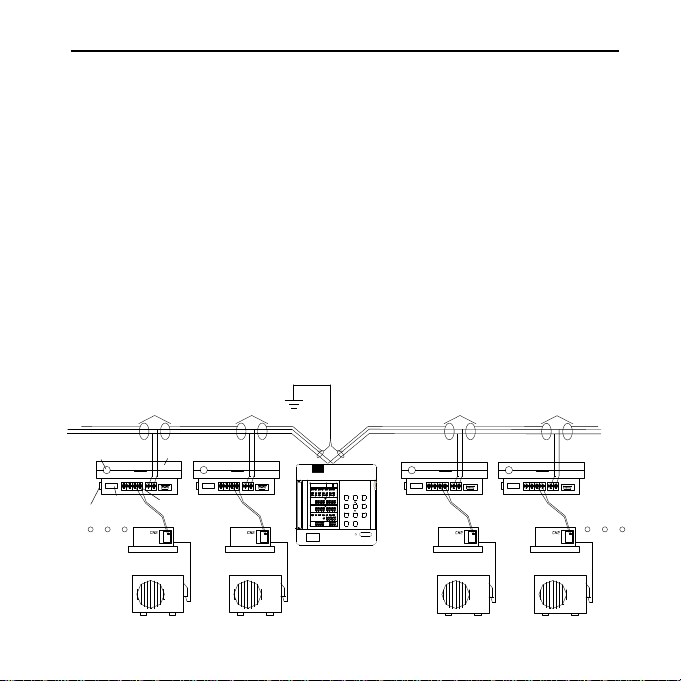
3. Use central controller + weekly timer to realize the group control function +
weekly timing function:
The detector is connected with one set of air conditioner by the 4-core screw fixed
terminals A+ and A- of air conditioner interface, then accordingly set the dial-code switch
of the detector in single unit working mode; the address number setting shall be performed
according the planned program, for specific setting and corresponding address, please
refer to the dial-code switch setting in detector's operation manual; use group controller
and weekly timer to fulfill the group control function with weekly timing function, the
system needs to be connected with group controller and weekly timer; each detector,
group controller and weekly timer is connected with shielded twisted pair communication
bus by the 2-core screw fixed terminals (A and B) of its RS-485 interface; the
communication bus must be shielded and grounded, and the resistors in its two ends
shall be suited.
RS-232
A RS485 B
PROGRAM
NO.
1 2 3 4 5 6 7
Number
HolidayProgram
SET 1 ON OFF
Hour
Cancel
SET 2 ON OFF
Min.
Confirm
1 2 3 4 5 6 7
Week
Time
NO.
ON/OFF
7
Page 9

System Outline
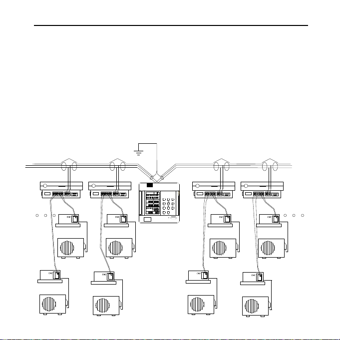
4. Use central controller and weekly timer to realize auto-changeover + group
control + weekly timing function:
The detector is connected with two same model air conditioners by the 4-core
screw fixed terminals of air conditioner interface; then accordingly set the dial-code
switch of the detector in double units working mode, and the double units switch
time is default 24 hours; the address number setting shall be performed according
the planned program, for specific setting and corresponding address, please refer
to the dial-code switch setting in detector's operation manual; use central controller
and weekly timer to fulfill double units switch group control function with weekly
timing function, the system needs to be connected with central controller and weekly
timer; each detector, central controller and weekly timer is connected with shielded
twisted pair communication bus by the 2-core screw fixed terminals (A and B) of
its RS-485 interface; the communication bus must be shielded and grounded, and
the resistors in its two ends shall be suited.
RS-232
A RS485 B
PROGRAM
NO.
1 2 3 4 5 6 7
Number
HolidayProgram
SET 1 ON OFF
Hour
Cancel
SET 2 ON OFF
Min.
Confirm
1 2 3 4 5 6 7
Week
Time
NO.
ON/OFF
8
Page 10

Operation Instruction
Instruction:
1 - PROGRAM-the display
shows the weekly timer timing
setting state, and in setting state,
the timing information can be
adjusted.
2 - No:8-timing group number:
when it is not set timing, there
is no timing group number; after
setting timing, it will
automatically form a group
number according to each kind
of setting combination, so that
in the sequent timing setting, it
can execute instant setting by
using timing group number.
3 - Setting state and holiday functional area-1 (MON), 2 (TUE), 3 (WED), 4 (THU), 5
(FRI), 6 (SAT), 7 (SUN) are used to indicate the 7 days in a week; the symbol of this
part will display after powered on; after set the corresponding weekday's timing function,
the ON symbol under the corresponding symbol will display, if not set timing, there will
be no display; if not set Holiday function, the OFF symbol on the upside of the indicating
symbol will not display, after set Holiday function, the OFF will display and at the same
time temporarily the previous timing setting and turn off the air conditioner.
4 - No. 1 group and No.2 group timing setting display area-when entering timing setting
state, the contents of timing will flash; choose Date, Hour and Minute to perform increase
and decrease adjustment by the adjusting key.
2
1
3
4
5
6
PROGRAM
NO.
1 2 3 4 5 6 7
SET 1 ON OFF
SET 2 ON OFF
1 2 3 4 5 6 7
NO.
Hour
Min.
Time
ON/OFF
Number
HolidayProgram
Cancel
Confirm
Week
9
7
8
9
14
16
10
15
17
11
13
12
18
Page 11

Operation Instruction
5 - Time display area-including display the weekday, hour and minute; before setting
timing function, please calibrate the current clock.
6 - Unit number trouble code display area-when the air conditioner in the control network
has trouble, the corresponding unit number and the trouble code will display in this area.
7 - Program
Enter or exit the timing setting in normal condition,
8 - Holiday
Close the units and invalid for timing in no affect on the timing setting condition.
9 - Number
Group setting and timing setting (take one day as a standard unit)
10 - Hour
Timing setting condition and time setting condition ,select the adjustment
11 - Min.
Timing setting condition and time setting condition ,select the adjustment
12 - Time
Enter and exit the at present date and time condition in normal condition
13 - Week
Timing setting condition and time setting condition ,select the adjustment
14 -
Timing setting condition and time setting condition , increase the setting parameters
15 -
Timing setting condition and time setting condition , decrease the setting parameters
16 - Cancel
Cancel the present setting before confirm the parameter.
17 - Confirm
Confirm the parameter.
18 - ON/OFF
Open/close the unit.
10
Page 12

Operation Instruction
1. Time adjusting function:
When powered on for the first time or after a long period of time
Press the Time key to enter time adjusting function;
(1)Continuously press Week key can adjust the current
date (weekday);
(2)Press Hour key/Min. key to choose the contents to be
adjusted, then use Increase key /Decrease key to adjust
time;
(3)Press Confirm key to confirm the above adjustment.
After confirming and the time works in the adjusted time;
or press Cancel key to cancel the adjustment and resuem
the previous state.
2. Timing data setting
(1)Press Program key to enter timing data setting state;
(2)Press Week key to choose the program setting date;
(3)Press Hour key/Min. key to choose the contents to
be adjusted, then use Increase key /Decrease key to
adjust time;
(4)After finishing data setting, press Confirm key to
confirm the setting and simultaneously switch to the
next timing section; or press Cancel key to cancel the
setting and resume the previous state; the weekly timer
can set two groups of Timer On/Off per day;
Number
HolidayProgram
Hour
Min.
Time
Hour
Min.
Time
Cancel
2
Confirm
3
4
Week
1
Number
HolidayProgram
1
Cancel
4
3
Confirm
5
Week
2
11
Page 13

Operation Instruction
(5)After finishing the data setting for a whole day, the controller will automatically
distribute a time number. In the sequent setting, if use the same timing setting data,
only choose the date to be set and choose the Number key, then press Confirm key;
Press Program key again to quit from the timing data setting state.
3. Holiday setting function:
(1)Press Holiday key to enter holiday setting function state;
(2)Press Week key to choose the date to set as holiday;
(3)Press Confirm key to confirm the set holiday function,
and simultaneously OFF will display on the top of the current
date;
(4)If set multi-days as holiday, repeat the above operation
till it is complied with requirements;
Holiday setting function is only valid in timing setting
function.
Hour
Min.
Time
Number
HolidayProgram
1
Cancel
Confirm
Week
2
3
12
Page 14

Maintenance
Weekly timer can display the malfunction unit number having trouble (the same as
detector setting address number) and the following trouble code. The corresponding
meaning of the trouble code are as the follow table show (including air conditioner
trouble and group control network trouble):
D4 D3 D2 D1 D0
0 0 0 0 0
0 0 0 0 1
0 0 0 1 0
0 0 0 1 1
0 0 1 0 0
0 0 1 0 1
0 0 1 1 0
0 0 1 1 1
0 1 0 0 0
0 1 0 0 1
0 1 0 1 0
0 1 0 1 1
0 1 1 0 0
0 1 1 0 1
0 1 1 1 0
0 1 1 1 1
1 0 0 0 0
1 0 0 0 1
1 0 0 1 0
1 0 0 1 1
1 0 1 0 0
1 0 1 0 1
1 0 1 1 0
1 0 1 1 1
1 1 0 0 0
1 1 0 0 1
1 1 0 1 0
1 1 0 1 1
1 1 1 0 0
1 1 1 0 1
1 1 1 1 0
1 1 1 1 1
Code
Meaning
No trouble(working normally)
1
Indoor ambient temperature sensor abnormal
2
Indoor pipe temperature sensor abnormal
3
Indoor heating overload protection
4
Indoor cooling freezing (overload) protection
5
Indoor unit and outdoor unit communication abnormal
6
Panel (wire controller) and indoor unit communication trouble (air conditioner
displays, central control displays 30)
7
Module abnormal (PFC protection-DC)
No load
8
Compressor overheat
9
CT current abnormal
10
Outdoor ambient temperature abnormal
11
Outdoor heat exchanger (pipe temperature) sensor abnormal
12
Power supply excess/lack voltage protection
13
High pressure protection
14
---Outdoor evaporator sensor abnormal
15
---Cooling overload
16
EEPROM abnormal
17
Outdoor return air sensor abnormal
18
Compressor sensor abnormal
19
---Indoor evaporator sensor abnormal
20
Drainage system abnormal
21
Power supply 3-phase abnormal (lack phase or wrong phase)
22
Humidity sensor abnormal
23
Indoor fan motor abnormal (fan motor over-current, fan motor IPM protection,
24
fan motor Hall components abnormal)
Outdoor fan motor abnormal (fan motor over-current, fan motor IPM protection,
25
fan motor Hall components abnormal)
Low pressure protection
26
---Electronic expansion valve abnormal
27
---Dust removing filter needs to be cleaned
28
Refrigerant is insufficient
29
Detector and air conditioner communication abnormal
30
Abnormal communication with the bus of detector
31
13
Page 15

Appearance/Dimension/Interface
RS-485
B A
12VDC
O
PROGRAM
NO.
1 2 3 4 5 6 7
SET 1 ON OFF
SET 2 ON OFF
1 2 3 4 5 6 7
NO.
Number
HolidayProgram
Hour
Cancel
Min.
Confirm
Week
Time
ON.
1 2 3 4
Installation and Debugging
1. The long-distance monitoring system group control network (hereinafter abbreviated
as group control network) of Haier Commercial Air Conditioner must establish, from
its design plan, installation and debugging to after-sale-service, a complete set of
documents (group control network programming, installation record, debugging record
and repair and maintenance record) and keep in the archives for future use.
2. The programming of group control network needs to finish the following works in
advance, including: (1) Composition of group control network system and control
number; (2) Choose the model of air conditioner, installation position, power distribution
and wiring treatment and connection with detector;
14
Page 16

Installation and Debugging
(3) Installation position of detector, address and unit number distribution, power
distribution and wiring treatment, connection with group control bus; (4) Installation
and wiring of group control bus, bus length limitation, the matched resistors at the two
ends of bus, the shielded layer of bus shall be single-point grounded; (5) Installation
position of central controller, address unit number distribution, power distribution and
wiring treatment.
3. The programming principle of group control network: (1) Detector is the essential
part; in order to guarantee proper response speed and reliable communication, the number
of detector equipped on the central controller shall not exceed 64; (2) The air conditioner
must be network air conditioner, and the installation must be performed according to
the attached operation and installation manual; in test run, cancel the air conditioner's
Power Failure Resume function; (3) It is recommended do not use the double units switch
function of the detector in the big load circumstance, that is it must be equipped with
group control network double units switch function, which requires the model of the
used air conditioners must be the same and the installation space is half of the general
installation space; (4) The installation position of the detector shall not be too far from
the air conditioner and shall not exceed the length of the connecting wire; (5) The detector
address unit number must be strictly distributed in the increasing sequence and set the
successive unit number; (6) Detector power distribution: the wiring shall not be too close
to the communication wire or pass through the same wire channel; no other special
requirements; (7) Connection of detector and group control bus: it is not allowed to
connect additional branch wire to the group control bus; (8) The shielded wire of detector's
air conditioner communication wire is short connected with the shielded wire of detector's
central controller communication wire; (9) The wiring of group control bus shall not be
too near the connecting wire or pass through the same wire channel; the rest can refer
to the wiring requirements of the storied building's auto control system; (10) The total
length of group control bus limits in 1000m; (11) At the ends of the bus and between A
bus and B bus shall respectively connect a 100 metal film precise resistor; address unit
number of central controller and weekly timer shall not be repeated;
15
Page 17

Installation and Debugging
(12) The bus shielded wire is single-point grounded. It is recommended to arrange it
in the middle part of the bus and near central controller or weekly timer; (13) The
installation position of central controller or (and) weekly timer arrange in the middle
part of the bus in principle and near the communication bus shielded grounding wire;
(14) The address unit number of central controller is set as default; the address unit
number of weekly timer is set as default; the central controller unit No. can't the same
as that of the weekly timer. (15) The central controller is in its own separate wiring
circuit; the wiring circuit and the communication circuit shall not be too close or pass
the same channel; no other special requirements; (16) The weekly timer uses 12VDC
power supply, which can be directly connected from the neighboring detector or
connected with other DC12V power supply; (17) Weekly timer can cooperatively use
together with central controller as a controller, or use weekly timer separately as the
only controller.
4. The wiring and installation of group control network will be done synchronously
together with the installation and debugging of network air conditioner. Please perform
test run before installation.
5. Connection of detector and air conditioner: The working mode and address unit
number of detector shall be performed strictly in line with the planned programming;
detector executes wire communication with at most two sets of air conditioners by the
air conditioner interface 4-core screw fixed terminals (A+, A-, B+, B-); the connection
of detector and air conditioner shall use the same wire; the inserted terminal at one
end of the wire is connected with the remote control interface on the air conditioner
PCB, the core wire at the other end of the wire is respectively connected with A+, A(B+, B-); the connection has polarity: generally the white wire connects A+/B+, black
wire/red wire connects A-/B-; in debugging, if the detector cannot work normally, it
can be checked by exchange between + pole and + pole. In powered on debugging, it
can also use the operation state displayed by the operation light (green LBD) to determine
whether the air conditioner communication interface is normal.
16
Page 18

Installation and Debugging
6. After finishing the wiring work of communication bus, perform the connection between
detector bus and communication bus: multiple detectors are parallel connected with
communication bus; all the A interfaces (including central controller or weekly timer)
are in the same bus; all the B interfaces (including central controller or weekly timer)
are in the other same bus; A interface wire and B interface wire at the end of the
communication bus is respectively connected a 100 metal film precise resistor; the
communication bus shielded wire is single point grounded in the middle part; the total
length of communication bus is limited in 1000m.
7. After finishing installation and connection of detector, perform central controller or
weekly timer connection with communication bus: central controller or weekly timer
connects with communication bus by RS-485 interface 2-core screw fixed terminals (A,
B); the connecting position is in the middle part of communication bus and near the
grounded point of its shielded wire.
8. Powered on debug: after powered on, the central controller will circularly monitor
the detectors and air conditioners in the communication bus. After searching a period
of time, the unit number shall expectedly display. If abnormal, perform check and debug.
9. After finishing debugging of central controller, powered on weekly timer. If at this
time appears disorderly communication, please check the address setting of weekly timer
and central controller. If communication normal, perform clock calibration and timing
setting. After the timing function achieves, finally perform Holiday function checking.
10. After debugging, record the debugging process, and after training the personnel,
deliver the engineering.
11. Setting of central controller's dial-code switch: if the dial-code switch is in OFF
position, indicates 0; if in ON position,
indicates 1. For the address number
setting, please refer to the
following table:
Note: D1, D2 not used
No.
D3, D4
1
2
3
4
17
0 0
0 1
1 0
1 1
Address
FFH
FEH
FDH
FCH
Page 19

Performance Parameter and Fittings
Power supply
Power consumption
Max dimension
Weight
Fittings
1PH DC12V / AC220V
2W
120x120x68
520g
Power supply connecting wire
User's Self-provide Parts
User's self-provide parts:
Group control bus: Recommend to use UL2547 type or equivalent
type twisted-pair shielded wire, and the specification is no less than
AWG20 (UL2547-202).
18
Page 20

Detector
1. Remote detector:
2. Group Control Detector:
power
R
YCJ-A002
Double/Single
9600/1200
S2
LED2yellow
SMG
LED3green
S1
INC
S3
SWITCHENTER
S5
EMERGENCY
DEC
S4
RD EMGYW GR
air conditioner
interface
YCJ-A002 sketch
open the cover
from here
-
+
LED1red
Choosing the detector type:
Remote detector is applicable to the environment with high electromagnetic disturbance,
and can operate and monitor by connecting to computer and air conditioner;
The cost of group control detector is low and applicable to the environment with low
electromagnetic disturbance. It can only form group control network and is economical.
19
Page 21

Central Controller
Central Controller
180mm
MONITER
SET
SELECT
UNIT
ON
OFF
LOCK
AUTO
MODE FAN
Total on/Total off
TEMP
TEMP.
TIME
ROOM
TEMP
TIME TIMER
CENTRAL
TIMER ON
EVERY DAY
TIMER OFF
REMOTE
CENTRAL
REMOTE
CONFIRM
120mm
(Fig.1)
64.4mm
As illustrated:
(Fig.2)
(Figure 1 is the front view and Figure 2 is the side view) The central
controller is 180mm long, 120mm wide and 64.4 mm thick.
20
 Loading...