

Haier XQJ60-31 Service Manual
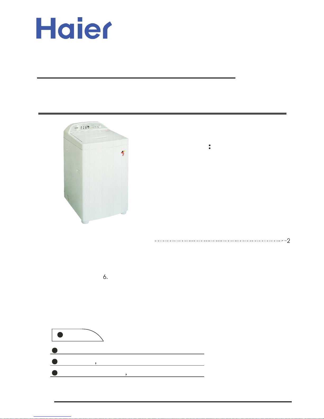
Computerized Automatic Washing Machine
·þÎñÊÖ²
SERVICE MANUAL
Models XQJ60-31
Edition: 2006.07.08
Special No.: HWM5TL
Features:
Top-head model,nice and elegant
Soak wash the wash result is more better
Eccentric plusator better effect
3.Names
of th
e
Parts................................................................3
4.Usage
o
f
Operati
ng
Knobs............................................................4
5.Product
Briefs
and
Major
Features..................................................5
..
..
.......7
7.Tr
ouble sh
ooting
.........................................................................13
8.Exploded
9.
view
of
the
compone
nts
...................................19
1.Table of
...........................................................1
2.Circuit Diagram
Contents
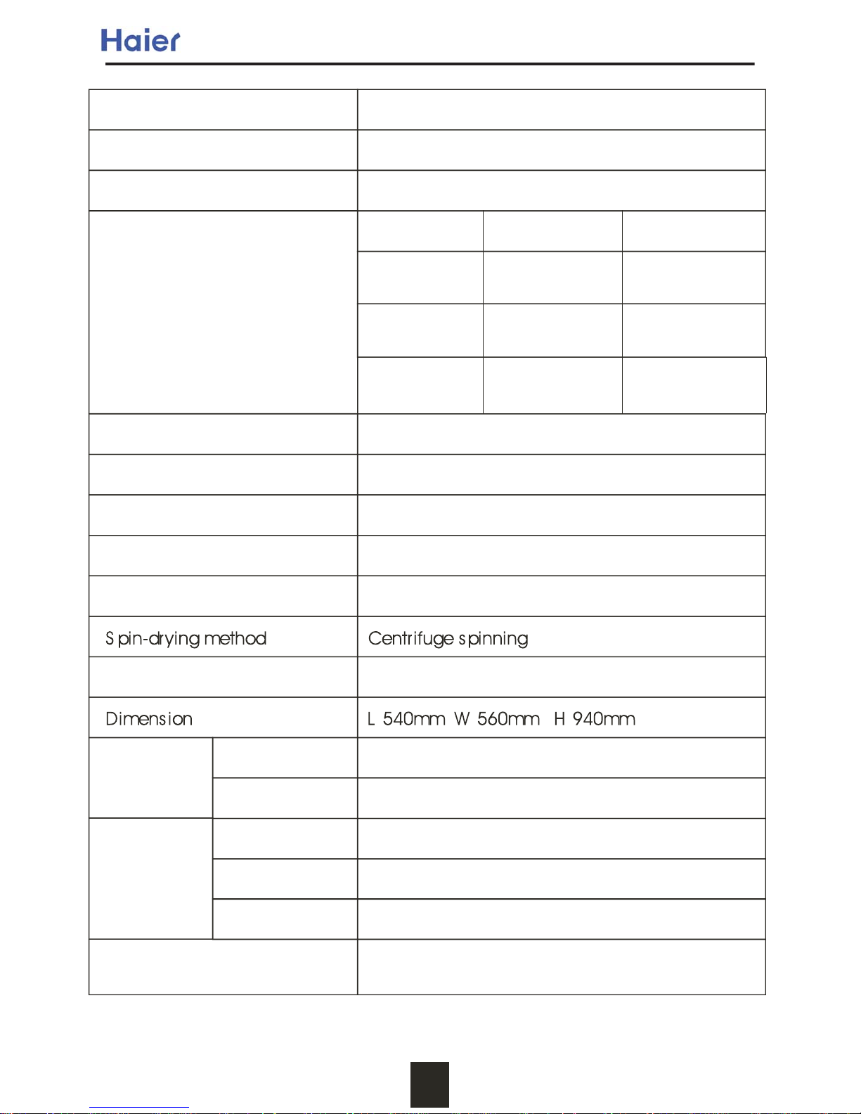
Specifications
Key Points in Installation, Adjustment and Disassembly
Components List
1
Programs
Safety
specifications
Large About 50L 3.5~4.5kg
Medium About 44L 2.0~3.5kg
Small About 35L 1.0~2.0kg
Model
Rated voltage * rated frequency
Rated wash/spin capacity
Water level and quantity
of different wash capacity
Water level W
ater quantity Wash capacity
HWM5TL
230-240V~ 50Hz
5.0kg (weight of standard dry cloth)
Standard water consumption About 150L (Large water level, NORMAL program)
Water inlet pressure 0.03Mpa~0
.78M
pa
Washing method Agitater current
Weight About 37kg
Water inlet pipe component, bottom plate,
tapping screws, user's manual,
Accessories
300W
450W
Ratedpowerconsumption
in spinning
Ratedpowerconsumption
in washing
Full auto
Manual
5A (interception
on
the
whole
circuit)
Motor With auto-resetthermalprotectiondevice
Capacitor with safeguardfunction
F r ee s election on w as hing pr ocedur es (ex cept QU ICK )
Power source
fuse
Table Of Specifications
HEAVY, NORMAL,GENTLE,QUICK WASH
2
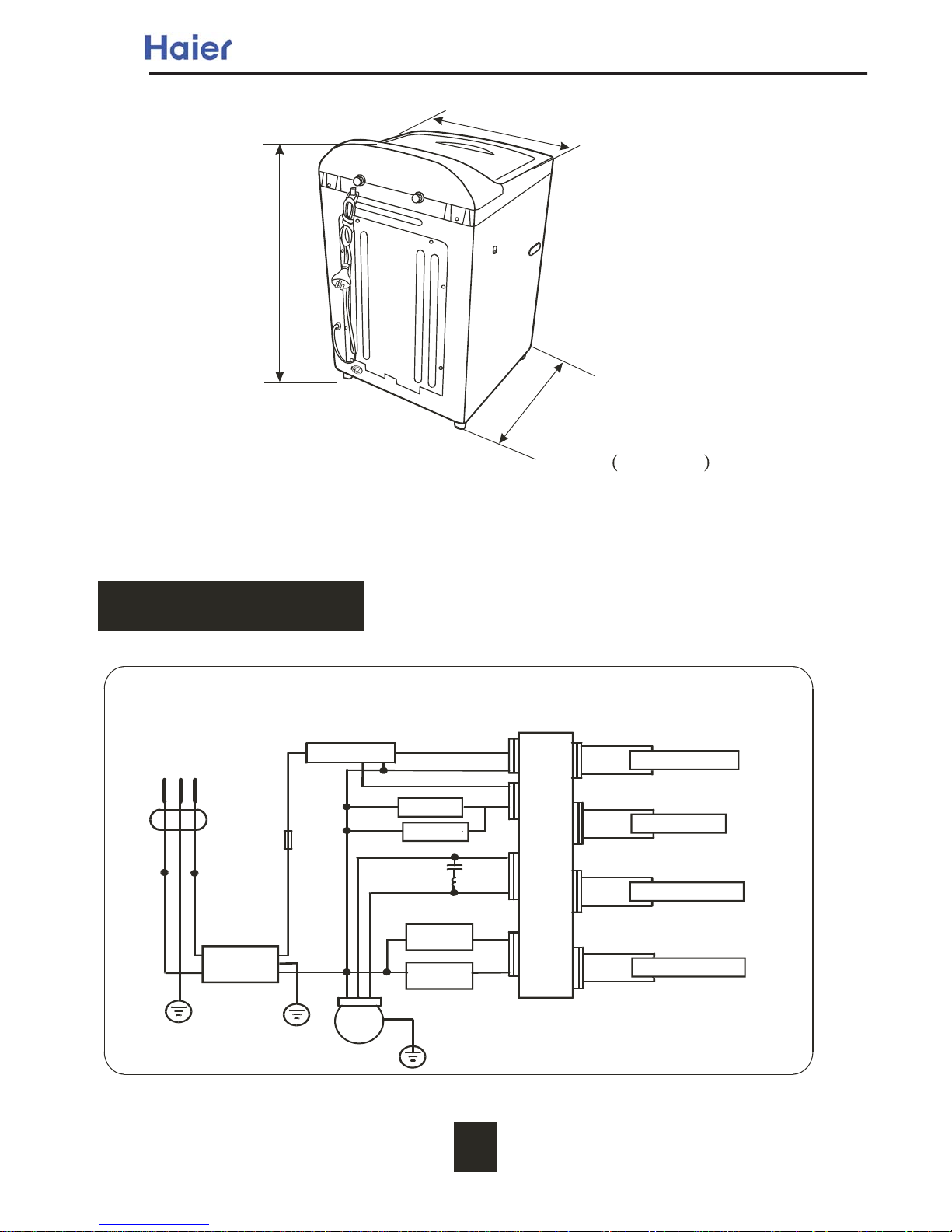
Overall Dimension Sketch
Circuit Diagr am
The
capacitor
coil
Lis
usedtoprotect
the
circuit,please
do
not
dismantle
it
Power switch
Fuse
Stop switch
Hot
wa
ter
inlet va
lve
Retractor
Macro-active switch
Red
Motor
Computer P r ogr am Contr ol l er
Blue
Orange
940
540
5
6
0
Unit:mm
C
L
5A
White
Tem
perature
s
ensor
Black
R/W
Red/Blue
Gray
Drain
Pump
Coldwate
r
inletva
lve
Blue
Blue
Water levelsensor
Pink
Orange
Purple
R/W
R/W
Pink
Gray
Gray
Blue
Blue
B lue/Whi te
Brown/White
Brown
Blue
Brown
Disturbance
Controller

Motor
Blue/White
Brown/White
Brown
Blue
Brown
Fuse
Blue
Drain pump
Retractor
Blue
Red/white
Gray
Gray
Temp eratu re
sensor
White Red
Gray
Blue
Orange
Powerswitch
Orange
Orange Orange
Gray
Red/Blue
Black
ColdWater
inletvalve
Hot Water
inletvalve
Pink
Waterlevel
Sensor
Stop switch
Macro-active
switch
R/W
R/W
Pink
Purple
Top lid
adjustable foot seam
The Actual Circuit Diag ram
Outer switch
Names of the par ts
Detergent box
Inner tubInner tubInner tub
Cabinet
Hight Pulsator
Co
ntr
ol
pa
nel s
ea
t
Adjustable foot
Back faceplate
Control panel film
Power switch
Power cord
Fixed foot
Wa
te
r
abs
o
r
pt ion
g
asket
Cold Water inlet
valve
Hook
Handle
Back cover
Drain hose bushing
Hot Water inlet
valve
Contr ol panel s eat
C
L
Disturbance
Controller
LARGE
ME DI U M
LITTLE
WAT ER
LEVEL
SOAK
WAS H
RINSE
SPIN
PROCESS
HEAVY
NORMAL
GE NT L E
QU I CK WA S H
WASH CYCLE
HOT/COLD
WARM/COLD
COLD / COLD
TEMP
SELECT
SELECT
START
PAUS E
T I ME R E MA I N I NG
TIMERON
DEL AY S TA RT
POWER S WIT CH
ON
OF F
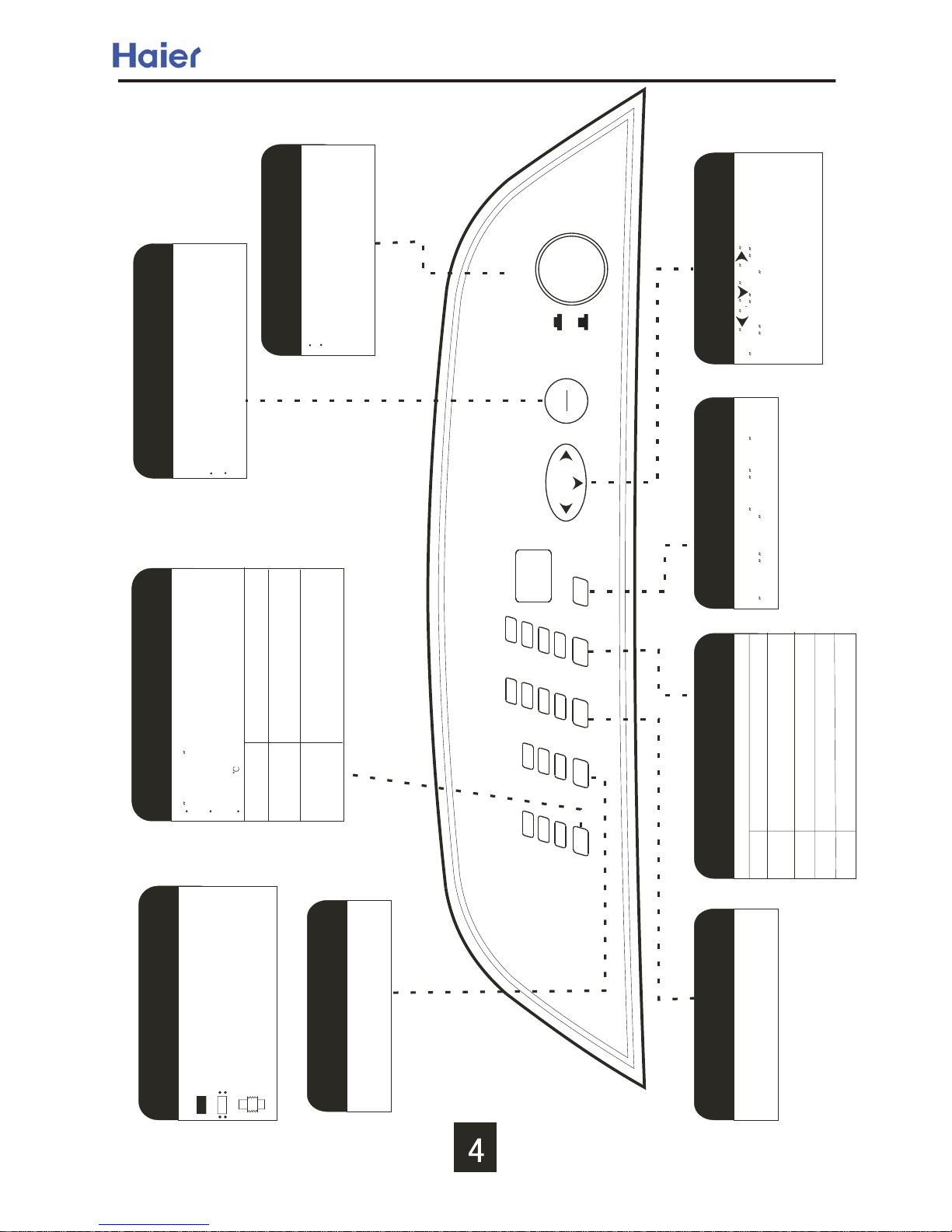
"T empselect" button
Cool water valveis set automatically when
washer is started.
P ush down thebutton, threety pes of water inlet
can be sel ected cold/col d, warm/w arm, hot/ cold.
P ay attention to thewater in drumnot being
over 50 .
Cold/Cold
Warm/Warm
Hot/cold
No r equi rement on wat er temperat ur e
T emper atur e of war m water i s h igh
and need to mix w ith s ome cool wat er
T emper atur e of war m wate r i s s ui table
or hi gher wat er temperat ure i n the
dr um is ex pected.
"Start/Pause" button
After s witch onthe power, push it once to start the
washing machine
I n operat ing, pu sh th e butt on to paus e th e oper ati ng.
I n pus hin g, pus h the bu tton to r es ume oper atin g.
Power switch button
P ush thebutton once to switch on thepower.
W hen the power i s on, pus h the button once
to cut off the power .
Water level selection button
P ush the button to select or adjus t
diff eren t water l evel.
P r ocedur e select ion button
P us h the button to s elect one or more pr ograms
fr om so ak, w as h r ins e and s pin .
Programbutton
S elect followingfour automaticprograms with thebutton
Program
Normal
Heavy
Quick
Gentle
A pplicabl e cir cums t ances
Washingthebigger,thicker or
heavier dirty laundries
Common washing
W ash ing the wool en tex til es or un derw ear
Quick washi ngof thel ight dirty laundries
Delay start button
P ush the button to select the reser ve
washing time among 4 hour 8 hour
12 hour 24 hour
Facti on sel ect but t on
Push or toselect
w as h cy cl e pr oces s wa ter
lev el t emp sel ect four
function.
I ndicat or made and meani ng
T he i ndi cator i s o ff, i ndicat ing th at the pr ogr am
or mode is n ot sel ected
T hei ndicator is flashing, indicating the running
pr ogram
T heindicator is on,indicatingthe programor
mode s electe d and about t o ru n
Usage of the Operation Knobs
Product Briefs and Major Features
<1>Product Briefs
(1) Computersequencer
It
adopts
pouring
seal with
polyurethane
on thesurface.The
light-emitting
diode
is
sealed
with
insulationbushing toavoid humidity.To avoid splashing,the
bottom
of the
control
panel
seat
wherethe
computer
plate
is installed
adopts
enclosed
structure,
and
the
surface
of
the
operation
componentsofthe
front
control
boardiscoated
with
control
panel
film.
(2) Structure of the top lid
intergrated
top
lid
structure.
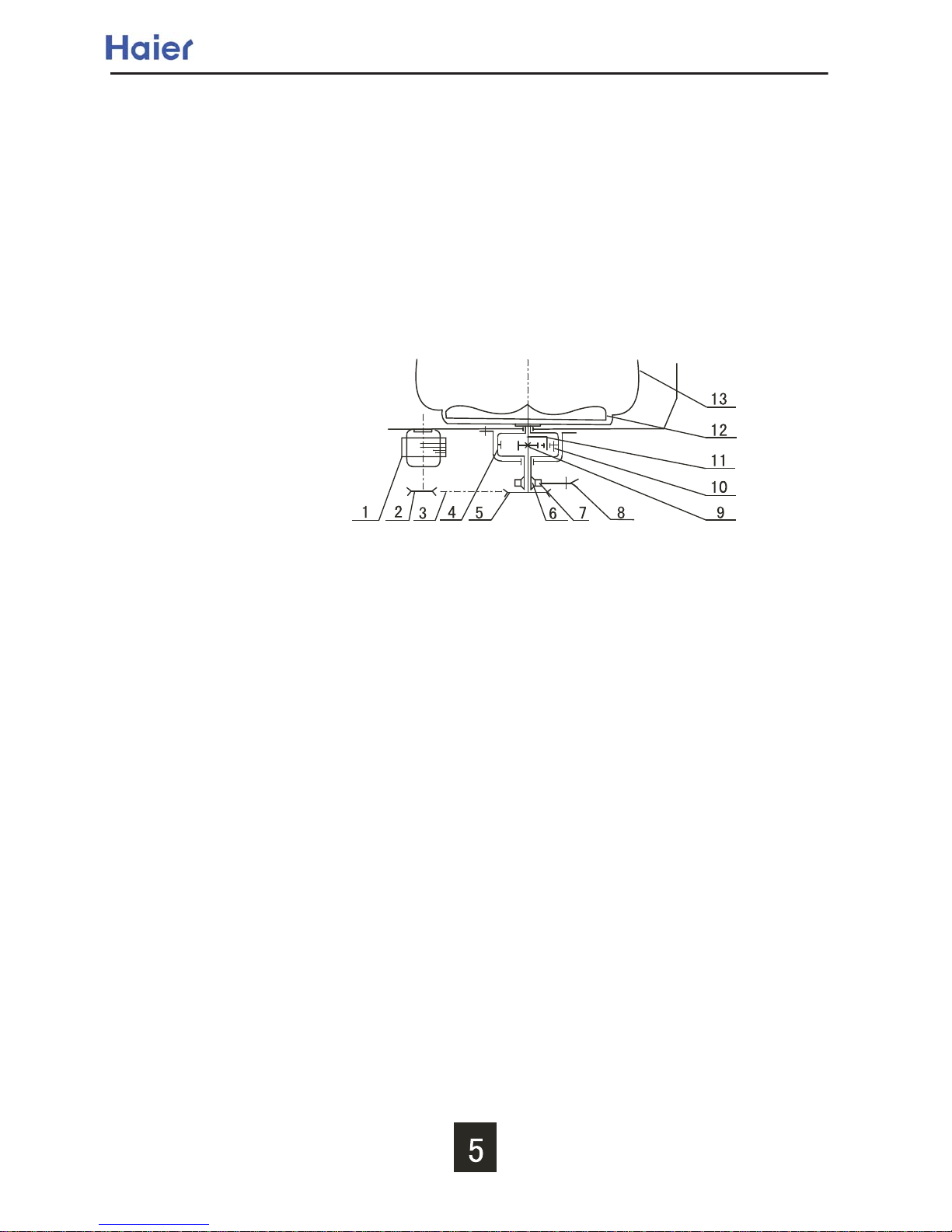
(3) Power transmission system
During washing, the rotation of Motor 1 is transferred to Follower 5 from Drive Wheel 2 through
Belt 3. Meanwhile, Ratchet 7 will be braked by Pawl 8 through the actionforce of the spring, and
the movement will be transferred to Center Gear 9, and then be retarded and transferred to
Tie-rod 10 through a planetary gear mechanismconsisting of Center Gear 9, Planet Gear 10 and
Spin Shaft 4 (inner gear), then Tie-rod 10 is connectedto Pulsator 12 via a spline shaft.Therefore,
Pulsator 12 will movealong with the clockwise andcounterclockwise rotation of the Motor 1.
During spinning, the rotation of Motor 1 is transferred to Follower 5 from Drive Wheel 2 through
Belt 3. Meanwhile, Pawl 8 will leave Ratchet 7 by the actionof the puller. Clutch Reed 6is twisted
tightly on the down part of Spin Shaft 4. The Spin tub 13 is connectedto Spin shaft 4 with flange.
The movement of Motor 1 will be retarded by V-belt, and then transferred to Spin shaft 4 and
make the Spin tub 13 to spin.
(4) Damping system
In installing the damping component, please note that the hangers at the motor side are
different from those of the other side. The motor side shall use the yellow spring. The other shall
use white spring.
 Loading...