

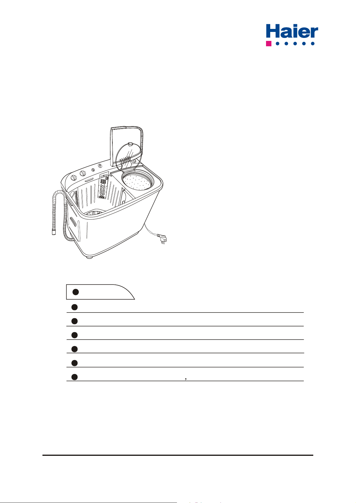
XPB90-99VGS
Twin-tub washing machine with pump
Service Manual
XPB90-99VGS(MALTA)
XPB90-99VS(AUSTRILIA)
Features
High head , unique shape
Large capacity , capable of more washing
Unique cascade current
Separating water and electricity , wide voltage range design
Enclosed base frame , mute design
Spray rinsing and spinning saving water and time
Haier Group
Special No.: SMXPB90-99VGS-02
Edition: 2003.01.12
CONTENTS
1.Contents 1
2. 1
Product code illumination and series introduction
3.
Features 2
4. 3
Specifications
5. Safety precautions 4
6. 5
Warning and cautions
7. Net dimension 6
8. 6
Installation and accessory parts
9. Parts and functions 10
10. Program list of wash timer 10
11. Maintenance service and trouble shooting 11
12. Wiring diagram 14
13. Exploded view 15
14. List of parts 17
PRODUCT CODE ILLUMINATION AND SERIES INTRODUCTION
X P B 90 - 99 V G S ( )
ABC D E
A:Washing machine
B:Ordinarily
C:Pulsator washing machine
D:Decuple of Capacity
E:Apperance code
F:Series
G:Twin-tub
H:Country
F
GH
1

High head , unique shape
Large capacity , capable of more washing
Unique cascade current
Separating water and electricity , wide voltage range design
Enclosed base frame , mute design
Spray rinsing and spinning saving water and time
With pump, drain up
With caster , move easily
Soak washing , more clean (XPB90-99VGS(AUSTRILIA))
FEATURES
2

SPECIFICATIONS
Model
Features for use
Wash capacity kg 9 9
Spin capacity kg 7.8 7.8
Level/Volume L 83/68/49 83/68/49
Preset H
Residual dampness %
Contral model
controller
Normal computerized
Fuzzy computerized
Frequency conversion
Service features
Programs
Short cycle
Inlet heating select
Heating selection
Spinning cycle (selector) 860 860
Spinning cycle (variable)
Start/Pause
Automatic balancing
Aesthetics
Cabinet m aterial P=Plastic/Z=Zincking/C=Cold )
Rolled stainless steel
Inner drum (stainl. steel=s / plastic=p)
Drain type drain up drain up
Door (glass=g / plastic=p) P P
Adjustable feet
Technical data
Voltage/frequency V/Hz 230-240V/50Hz 220-240V/50Hz
Wash power W 560 560
Spin power W 325 325
Special function
Air-Bubble
Feet wheel
Water fall current
Dimensions (measurements)
Height / built under cm 98.6 98.6
Width cm 87.6 87.6
Depth / with open door cm 50 50
Net weight kg 45 45
NOTES: "
" FOR AVALIABLE, " " FOR NOT AVALIABLE , "-"FOR BE APPLICABLE
XPB90
99VGS
(AUSTRILIA)
100 100
ZZ
PP
XPB90 99VGS
(MALTA)
3
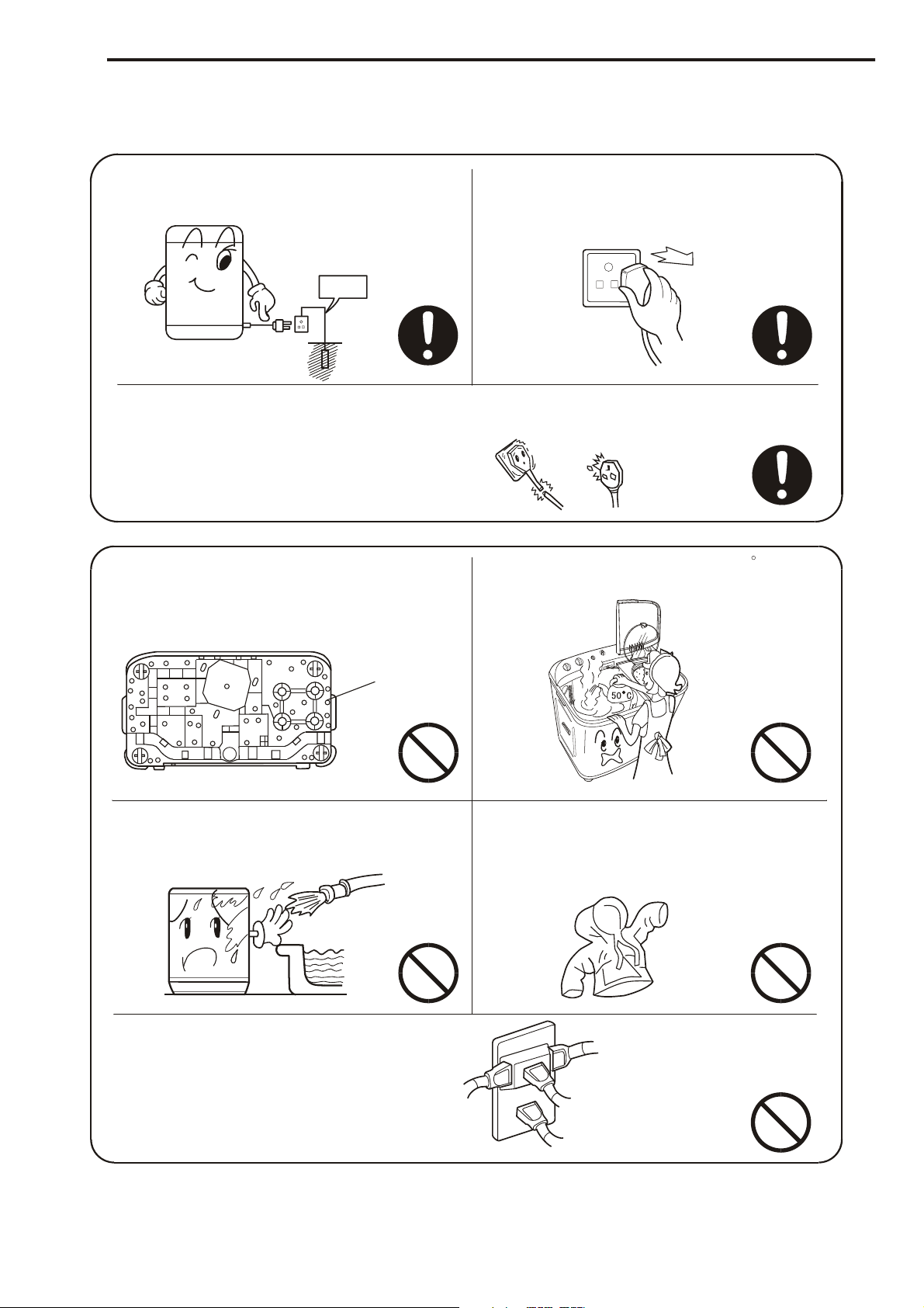
SAFETY PRECAUTIONS
Be sure to use three-pins receptacle.
Earth the earthing terminal of the
receptacle reliably.
Be sure to pull the plug off when there's
power failure, or the machine is being
moved, cleaned or when it is idle.
Earth
If the power cord is bad, to avoid risk it is required to replace it by the technicians
of our special shop or the after-sale service department. Keep the pin of the power
plug clean.
In case the washing machine is installed
Do not use water hotter than 50 C .
on ground with carpet , do not block the
ventilation hole with carpet.
Ventilation hole at
the bottom of the
washing machine
Do not put the machine at damp place
like the bathroom . Never wash it with
water.
Do not share one receptacle with other
electric appliances. Do not use it in
case that the power plug is damaged
or the inserting into the receptacle is
loose.
Do not wash water-proof laundries such
as the raincoat, bicycle shelter etc. To
avoid abnormal vibration during spinning.
4
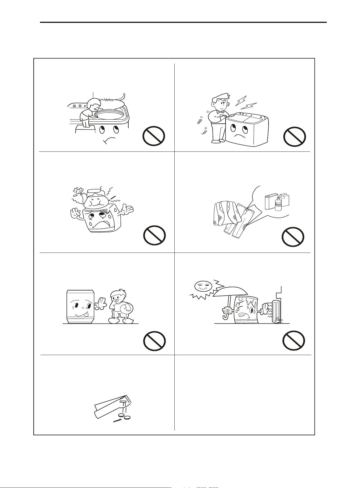
WARNING AND CAUTIONS
Do not stretch hands into the working
machine. It is dangerous even if the
rotation is slow. Take special care of
the children.
Do not put any hot or heavy items
( such as the kettle with hot water )
on the washing machine.
Do not decompose, repair or alter the
machine by yourself.
Do not wash laundries with volatile
materials (such as thinner, petrol etc.).
l
Petro
Thinner
Handicapped or children without care
shall not use the machine.
To prevent your laundries and washing
machine from damage , be sure to take
out of the foreign materials from your
pocket , such as coins, buttons, sand
or hair pins etc.
Keep the machine away from direct
sunlight and heat source like the
heater.
Before washing, please check if the
water tap is open, and if the water inlet
pipe is connected properly.
It is suggested to use low-foaming
washing powder
5
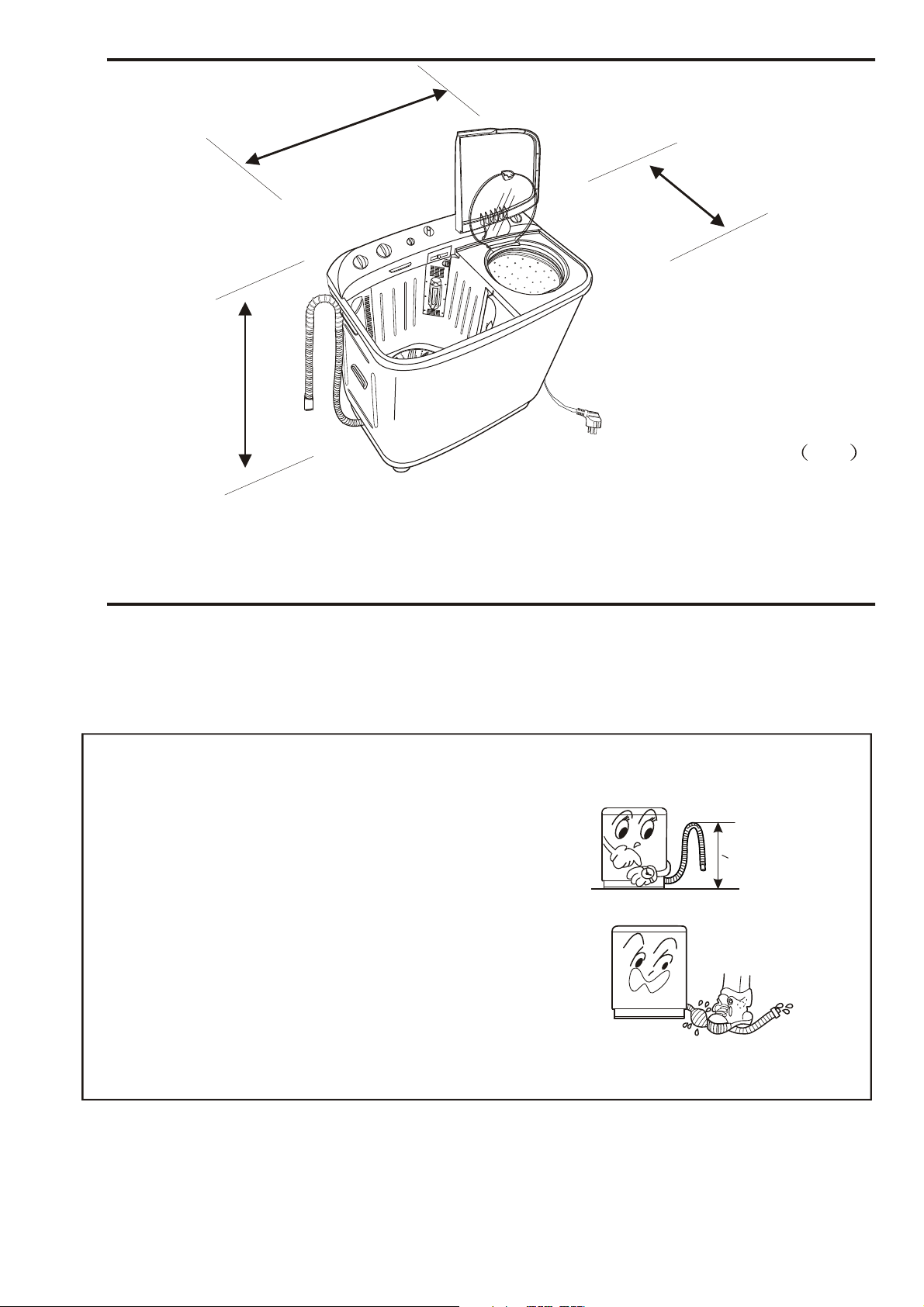
986
NET DIMENSION
876
500
Unit mm
INSTALLATION AND ACCESSORY PARTS
Usage of the drain hose
The drainage shall be smooth with the drain hose.
1 put the drain hose up to the suitable position.
2 do not tramp or squeeze the drain hose.
<1.2m
6

INSTALLATION AND ACCESSORY PARTS
How to change the direction of the drain hoses
Figure 1 indicates the ex factory installation
position of the drain hose.
Soft item
Extend the drain hose from the side of spin tub
Put soft items on the ground. Lean the machine
down gently with the front surface facing the
ground. Take off the drain hose from the cabinet.
Dismantle the drain hose fixing clamp and take
the hose out of the fixing groove.
(See to Figure 2).
Drain hose fixing clamp
Back
Front
Figure 1
Soft item
Embed the drain hose into the groove along the side
of the spin tub in the order of (1)~(3), heading for the
side of the spin tub. (See to Figure 3).
Extend to the
spin tub side
Embed the drain hose into the groove with
hands. Take care not to damage the drain
hose in fastening the fixing clamp.
Extend the drain hose from the rear side
Dismantle the drain hose fixing clamp.
Take out the drain hose from the fixing groove.
Extend it from the rear side as per the direction
of the arrow. (When the drain hose is extended
from the rear side, it can be hung on the point
for drain hose at the two sides of the cabinet.)
(See to Figure 4).
Figure 2
Embed into the
groove in turn
Figure 3
Figure 4
7

INSTALLATION AND ACCESSORY PARTS
Points of Attention in After-sales Service
Be sure to switch off the power during dismantling or repair.
Be sure to use insulated wiring terminals and insulation box in connection of the wires, and
crimp and fix to proper position with suitable tools.
In welding connections with electric iron, be sure to twist the wires before welding, and insulate
with insulation tapes.
In welding the wires with electric iron, be sure not to touch the resin part and insulation part of
each switch.
The inlay connection wires and terminals shall not be loose or drop.
Do not make the wires touch the moving parts like the belt, pulley of the motor, brake bar etc.
Do not make the wires touch the sharp edges and high-temperature area.
In case that there are metal parts with the wires, do not make the wires touch the metal parts.
Insulation materials are needed between them.
After assembly, the washing machine shall act normally. Check if it leaks and if the sound and
vibration are normal.
Dismantling and installation of the control panel component
Loosen the fastening screws. Pull towards the direction indicated
in the figure to dismantle the control panel. In installation the
beard shall lock into the installation hole of the water reception
groove and the spin tub frame. (Figure 5)
Dismantling and installation of the spin tub frame component
Dismantle the control panel component. Loosen
the two fastening screws at the rear of the spin
tub frame to dismantle the component.
Dismantling and installation of
the spin tub
Dismantle the spin tub frame component.
Loosen the fastening screw of the spin tub
shaft. The spin tub then can be taken out.
In installation, be sure to inlay the bulge of
the inner lining of the brake wheel into the
groove of the spin tub shaft. (Figure 6)
Figure 5
Spin tub shaft
Bearing seat
Oilite bearing
Inner lining of
the bearing seat
Fastening screw
Inner lining of the
brake wheel
Fastening screw of
the brake wheel
Brake wheel
Spin motor shaft
Figure 6
8

INSTALLATION AND ACCESSORY PARTS
Adjust the tension of the belt
Loosen the fastening screw at the back of the
base frame. Move the shift fixing gasket along
the direction indicated in the figure to adjust
the tension of the belt. After adjusting, fasten
the screw. (Figure 7)
Dismantling and installation of the base frame
Dismantle the back cover. Loosen the wires.Loosen the fastening screw
of the spin tub shaft. Separate the shaft from the brake wheel. Loosen
the brake hook. Take off the brake cable frame from the installation groove
of the twin-tub.Take off the V-belt. Take out the drain hose from the groove
of the base frame. Loosen the fastening screw between the base frame
and the cabinet to dismantle the base frame component.
Figure 7
Dismantling and installation of the bearing seat
Once the bearing seat is taken off, it can not be utilized again. Therefore do not dismantle
it as far as possible. In case that it has to be replaced, please dismantle it as per following
sequence, then install a new bearing seat.
a. Dismantle the spin tub as per Clause .4. Then pull out the bearing seat.
b. Cut off the inner lining claw inside the bearing seat with cutting pliers and take it out.
c. Install the new bearing seat and inner lining.
d. The bearing seat is an inlay component. Be sure to aim the claw of the inner lining
at the hole of the tub then push it in. Please use suitable tools and add even pressure
around the tub.
e. After inlay the bearing seat, check if the claw is installed to proper position from the
out side of the twin-tub (Figure 8).
Right
Wrong
Figure 8
9

Water inlet
Inlet selection
Buzzer
Current change
Wash timer
Control panel
Cascade outer
Filter frame
PARTS AND FUNTIONS
Spin tub outer cover
Spin tube inner cover
Spin timer
Spin tub frame
Spin tub
Lint filter
Pulasor
Wash tub
Drain hose
DIAGRAM LIST OF XPB90-99VGS(MALTA)
0 310
15min 2min
a
S1
b
17s 12s
a1
a
a2
S2
b
a3
a
b1
a4
b2
S3
b3
b
b4
Cabinet
Power cord
Base frame
PROGRAM LIST OF WASH TIMER
S2 strong S3 standard
symbol time limit S symbol time limit S
6
1.8
1.8
1.5
0.8
0.6
1.5
6
0.8
0.6
a1 On a3 On
a2 Off a4 Off
b1 On b3 On
b2 Off b4 Off
b
a
4.5
1
0.8
3.3
0.5
0.8
4.5
1
0.8
3.3
0.5
0.8
S2(S3)
a
10
S1
Wash timer
b

MAINTENANCE SERVICE AND TROUBLE SHOOTING
Insert the power plug , but the machine does not work
Wash part
Check if the wash timer is opened ?
YES
Check if the power source is available
YES
Check if the contact between the plug
and receptacle is good
YES
Check if the power supply
cord is good
YES
NO
NO
NO
NO
Open the wash timer
Switch on the power
Replace the plug
or receptacle
Replace with new power
supply cord
Check if the capacitor
is good
Replace the capacitor
Check if the lead connection-peg is good
YES
Check if the fuse is good
YES
Poor contact or inferior
inside of the wash timer
YES
Replace the wash timer
NO
NO
NONO
Insect the lead well again
Replace the fuse
Check if the motor is good
NONO
Replace the motor
11

Spin part
MAINTENANCE SERVICE AND TROUBLE SHOOTING
Check if the spin timer is opened ?
YES
NO
Open the spin timer
Check if the power source is available
YES
Check if the contact between the plug
and receptacle is good
YES
Check if the power supply
cord is good
YES
Check if the lead connection-peg is good
YES
NO
NO
NO
NO
Switch on the power
Replace the plug
or receptacle
Replace with new power
supply cord
Insect the lead well again
Check if the capacitor
is good
NO
Replace the capacitor
Check if the fuse is good
YES
Check if the microswitch is closed
YES
Check if the motor is good
YES
Check if the brake system is detached?
NO
NO
NOYES
NO
Replace the fuse
Repair the microswitch,
make it closed
Replace the motor
Repair the brake system
12

MAINTENANCE SERVICE AND TROUBLE SHOOTING
There is metal rubbing noise in braking
If the brake arm has brake block ?
The washing noise is too large
Is the motor noise large?
NO
Is the motor fastened tightly?
YES
Is the belt too loose or too tight?
NO
NO
YES
NO
YES
Add the brake or
replace the brake arm
Replace the motor
Fasten the motor tightly
Adjust the tension of the belt
Is the radiating pulley loose?
YES
Fasten the radiating pulley
NO
Is the pulsator rubbing the
bottom of the twin-tub?
YES
Adjust the gap between the
pulsator and the twin-tub
The pulsator only rotates towards one direction
First check if the inlay connection is OK . If so please replace the wash timer.
Poor contact inside of the wash timer
YES
Replace the wash timer
NO
Adjust the connection to
right position
13

WIRING DIAGRAM
There is overload protector installed in the motor. In case that the motor is overload or meets
breakdown in working, the protector will act and stop the motor. When the breakdown is
removed, the motor will resume normal working.
Actual Circuit Diagram
Drain switch
Brown
Drain
Pump
White
Control
panel
Cabinet
Wash timer
Yellow
Red
Red
Wash
Motor
Brown Brown
Gray
Yellow
Spin timer
Microswitch
Orange Orange
Fuse
Brown
Blue
Purple
Yellow
Red
Capacitor
Gray
Purple
Blue
Purple
Gray
Buzzer
Spin
Motor
Gray
14
Blue

EXPLODED VIEW
20
12
14
30
31
34
38
10
1
9
11
37
39
27
142
29
235
8
13
17
18
16
73
81
85
68
86
70
46
69
78
87
88
80
78
83
84
79
71
72
4
135
7
136
62
61
60
40
82
67
66
129
65
64
63
41
74
76
77
78
81
59
140
141
32
33
35
36
47
133
42
43
44
89
15
90
45
Carton box
58
15
52
28
53
54
56
21
Manual

EXPLODED VIEW
92
91
23
121
111
122
112
137
138
24
110
93
118
119
99
117
94
109
26
100
101
116
95
102
103
23
96
104
105
106
107
108
139
97
98
75
130
128
55
49
131
132
120
114
113
112
134
25
22
92
123
124
125
126
127
57
106
104
106
115
19
50
51
104
105
48
16

No Parts Code Parts Name Model QTY Remark
1 0030200363 Wash tub cover All-purpose 1
2 00330603049 Kick spring All-purpose 1
3 0030200365 Spin tub cover All-purpose 1
4 00330901529 Notice label All-purpose 1
5 00330029022 Brake pullback component All-purpose 1 *
6 00330503500 Microswitch All-purpose 1 *
7 00330810009 Tapping screw All-purpose 3
8 00330043004 Spin tub frame component All-purpose 1
9 00330015008 Water channel A component All-purpose 2
10 00330810009 Tapping screw All-purpose 2
11 00330015009 Guide slot A components All-purpose 2
12 00330019010
13 00333101049 Filter frame All-purpose 1
14 00330015011 Guide slot B component All-purpose 1
15 0030802452 spin tub component All-purpose 1
16 0030201873 Lint filter All-purpose 1 *
17 00330810009 Tapping screw All-purpose 3
18 00333101147 Flat valve cover All-purpose 1
19 00330014038 Damping spring component All-purpose 4 *
20 00330203010 Small block All-purpose 3
0030502281
0030502950 XPB90-99VGS( MALTA)
21
22 0030801588 Brake panel A component All-purpose 1
23 00330812061 Bolt A component All-purpose 2
24 00330104001 Anti-deformation strip All-purpose 1
25 00330802095 Tapping screw All-purpose 7
26 0034200060 Capacitor All-purpose 4 *
27 0030600056 Pulsator fixing screw All-purpose 1
0030502282
0030502943 XPB90-99VGS( MALTA)
28
29 00333101124 Pulsator All-purpose 1
30 00330303028 Pulsator cover All-purpose 1
31 00333101069 Twin-tub All-purpose 1
32 00330602060 Water channel block All-purpose 1
33 00330602061 Water channel block A All-purpose 2
34 00330810009 Tapping screw All-purpose 12
35 00330067005
36 00330802062 Tapping screw All-purpose 4
37 00330603011
38 00330810009 Tapping screw All-purpose 1
39 00330109030
40 00330029023
41 00330106004 Long overflow pipe All-purpose 1
Water channel B component All-purpose 1
XPB90-99VS(AUSTRILIA)
mannual 1
XPB90-99VS(AUSTRILIA)
Packing box 1
Damping clutch
Locating lever
Pullback band pulley
Drain pullback band component
All-purpose 1 *
All-purpose 1
All-purpose 1
All-purpose 1
LIST OF PARTS
Notes: the components marked with * in the remarks columns are damageable parts.
17

No Parts Code Parts Name Model QTY Remark
42 00330107085 Overflow pipe All-purpose 1
43 00333101030 Valve body All-purpose 1
44 00330203007 Valve plug All-purpose 1
45 00333101140 Valve rod All-purpose 1 *
46 0030501168 Warning label All-purpose 1
47 00330605502 Drain hose clamp All-purpose 2
48 0030800456 Outer drain hose component All-purpose 1 *
49 00333101072 Base frame All-purpose 1 Sea grey
50 0030200752 Tightening mat All-purpose 4
51 00330802017 Tapping screw All-purpose 4
52 00330603061 Valve spring All-purpose 1
53 00333101031 Valve cover A All-purpose 1
54 00330810009 Tapping screw All-purpose 4
55 00330812069 Nut All-purpose 3
56 00330106005 Safeguard bag All-purpose 1
00330502020
00330502530 XPB90-99VS(AUSTRILIA)
57 1
Ground wire parts
XPB90-99VGS( MALTA)
58 0030801662 Bearing seat component A All-purpose 1 *
59 0030803377 Accessories
XPB90-99VGS( MALTA) 1
60 00330101092 Water filli ng guide slot All-purpose 1
61 00333101067 Water channel All-purpose 1
62 00330109028 Gliding block All-purpose 1
63 00330810009 Tapping screw All-purpose 2
64 00330111532 Water filli ng control handle All-purpose 1
65 00330104003 Stabling block All-purpose 2
66 00330101095
Connecting rod
All-purpose 1
67 00330603505 Small pullback spring All-purpose 1
68 00330101096 Expansion gasket All-purpose 1
69 00330502145 Wires module All-purpose 1
00330501009 Other-purpose
00330501018
Wash timer 1 *70
XPB90-99VS(AUSTRILIA)
71 00330906195 Excess filling label All-purpose 1
00330111293 Other-purpose
0030200950
72
0030502284 XPB90-99VS(AUSTRILIA)
0030502940 XPB90-99VGS( MALTA)
73
Wash shelf
Print control panel
XPB90-99VS(AUSTRILIA)
1
1
74 00330111538 Knob All-purpose 3 *
75 00330602017 Outer drain hose clamp All-purpose 1
76 0030600001 Tapping screw All-purpose 3
00330111294 Other-purpose
0030200951
Spin shelf 177
XPB90-99VS(AUSTRILIA)
78 00330802005 Tapping screw All-purpose 10
79 00330501013 Spin timer All-purpose 1 *
LIST OF PARTS
Notes: the components marked with * in the remarks columns are damageable parts.
18

No Parts Code Parts Name Model QTY Remark
00330111295 Other-purpose
0030200952
81 00330802005 Tapping screw All-purpose 5
82 00330312502
83 00330513517 Buzzer All-purpose 1 *
84 00330802025 Tapping screw All-purpose 2
85 00330109018 Selector cam All-purpose 1
86 00330802025 Tapping screw All-purpose 1
87 00330906500 Water filli ng label All-purpose 1
88 00330810009 Tapping screw All-purpose 3
89 00330802500 Tapping screw All-purpose 2
90 00333101041 Drain hose fixing clamp All-purpose 1
91 0030600001 Tapping screw All-purpose 5
92 00330829001 long locking band All-purpose 2
0030502283
0030502942 XPB90-99VGS( MALTA)
93
94 00333101562 Power cord hook All-purpose 2
95 00330802500 Tapping screw All-purpose 2
96 00330101854 Back cover All-purpose 1
97 00330802500 Tapping screw All-purpose 9
98 00330028011
99 00330101655 Wire holder All-purpose 1
100 00330802007 Tapping screw All-purpose 1
101 00330101894 Cabinet handle All-purpose 2
102 00330103501 Fixing pin All-purpose 1
103 00330308502 Power cord fixing clamp All-purpose 1
104 00330804001 Screw All-purpose 3
105 00330804003 Gasket All-purpose 2
106 00330806003 Notched gasket All-purpose 3
107 00330804002 Nut All-purpose 2
0030400126
00330802133 XPB90-99VGS( MALTA)
108
109 00330308049 Cabinet All-purpose 1
110 00330802500 Tapping screw All-purpose 2
111 0030400237 Capacitor cord Other-purpose 1
112 00330301023 Capacitor fastening ring All-purpose 2
113 00330205021 Damping gasket, lower All-purpose 3
114 00330205020 Damping gasket, upper All-purpose 3
115 00330603013 Pullback spring All-purpose 1
116 00330047001 Brake wheel component All-purpose 1 *
117 00330812048 Fixing screw All-purpose 1 *
118 00330812043 Screw All-purpose 3
Buzzer shelf 80
Positioning spring
Nameplate 1
Brake strand cord component All-purpose 1
Power cord 1
XPB90-99VS(AUSTRILIA)
All-purpose 1
XPB90-99VS(AUSTRILIA)
XPB90-99VS(AUSTRILIA)
1
LIST OF PARTS
Notes: the components marked with * in the remarks columns are damageable parts.
19

No Parts Code Parts Name Model QTY Remark
119 00330820004 Spring gasket All-purpose 3
120 00330812070 Bolt All-purpose 3
121 00330401016 Radiating pulley All-purpose 1 50Hz
122 00330011021 V-belt All-purpose 1 *50Hz
123 00330812071 Screw All-purpose 3
124 0034000189 Spin motor All-purpose 1 *240V~50Hz
125 00333101008 Motor insulation seat All-purpose 3
126 00330802017 Tapping screw All-purpose 4
127 00330301130 Motor fixing plate All-purpose 1
128 0034000188 Wash motor All-purpose 1 *240V~50Hz
129 00330111285 Hinge seat All-purpose
130 0034000121 Drain pump All-purpose 1
131 00330302033 Drain pump seat All-purpose 1
132 00330206502 Damping seat All-purpose 4
133 00330107108 Inner drain pipe All-purpose 1
134 00330812514 Tapping screw All-purpose 3
135 00330503060 Drain switch All-purpose 1
136 00330802052 Tapping screw All-purpose 2
137 00330506522 Disturbance controller All-purpose 1
138 00330205001 Rubber band All-purpose 3
139 0030400029
140 0030801995 Water inlet pipe XPB90-99VS(AUSTRILIA) 1
141 00330107106
142 00330303505 Tooth gasket All-purpose 1
Dist urbanc e controller power cor d All-purpose 1
Gland XPB90-99VS(AUSTRILIA) 1
LIST OF PARTS
Notes: the components marked with * in the remarks columns are damageable parts.
20

Sincere Forever
Haier Group
Tel: 86-532-8938356
Web site: http: //www.haier.com
 Loading...