

Page 1
Vertical Display and Storage
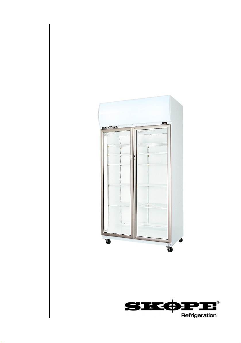
TME650/1000
SKOPE One and Two Door Vertical Chillers
Installation and Operating Instructions
MAN7461 Rev. 2.0 July 2006 edition
Page 2

TME650/1000
SKOPE One and Two Door Vertical Chillers
Installation and Operating Instructions
MAN7461
Rev. 2.0 July 2006 edition.
Copyright © 2006
SKOPE Industries Limited.
All rights reserved.
SKOPE Industries Limited reserve the right
to alter specifications without notice.
is a registered trade mark
of SKOPE Industries Limited.
TRADE MARK INFRINGEMENT
The SKOPE trade mark on this product is infringed if the owner, for the time
being, does any of the following:
•Applies the trade mark to the product after their state, condition, get-up
or packaging has been altered in any manner
•Alters, removes (including part removal) or obliterates (including part
obliteration) the trade mark on the product
•Applies any other trade mark to the product
•Adds to the product any written material that is likely to damage the
reputation of the trade mark
Notice of the above contractual obligations passes to:
•Successors or assigns of the buyer
•Future owners of the product
i
SKOPE One and Two Door Vertical Chillers
TME650/1000
Page 3

TABLE OF CONTENTS
1INSTALLATION
1.1Safety Information. . . . . . . . . . . . . . . . . . . . . . . . . . . . . . . . .4
1.2Positioning the Cabinet . . . . . . . . . . . . . . . . . . . . . . . . . . . . .5
1.3Fitting the Sign Unit. . . . . . . . . . . . . . . . . . . . . . . . . . . . . . . .6
1.4Fitting the Shelves. . . . . . . . . . . . . . . . . . . . . . . . . . . . . . . . .7
2OPERATION
2.1Cabinet Operation. . . . . . . . . . . . . . . . . . . . . . . . . . . . . . . . .8
3MAINTENANCE
3.1Lighting . . . . . . . . . . . . . . . . . . . . . . . . . . . . . . . . . . . . . . . . .9
3.2Cleaning . . . . . . . . . . . . . . . . . . . . . . . . . . . . . . . . . . . . . . .11
3.3Advanced Servicing. . . . . . . . . . . . . . . . . . . . . . . . . . . . . . .12
3.4Contact Addresses . . . . . . . . . . . . . . . . . . . . . . . . . . . . . . .12
TME650/1000
SKOPE One and Two Door Vertical Chillers
ii
Page 4

INSTALLATION
1
1.1Safety Information
When using any electrical appliance, safety precautions should
always be observed. Read these instructions carefully and retain for
future reference.
•When used by, or near, young children or infirm persons, close
supervision is necessary. Young children should be supervised
to ensure that they do not play with the appliance.
•Do NOT use this appliance for other than its intended use.
•Do NOT cover the grilles or block the entry or exhaust of airflow
by placing objects up against the refrigeration unit.
•Do NOT probe any opening.
•Only use this appliance with voltage specified on the rating label.
•Ensure adequate ventilation of the SKOPE refrigeration unit.
•Be careful not to touch moving parts and hot surfaces.
•Regulations require that all electrical work be carried out by
authorised persons. For your own safety, and that of others,
ensure this is done.
•If the supply cord becomes damaged, it must be replaced by a
SKOPE authorised service agent, or similarly qualified person,
in order to avoid a hazard.
•If the refrigeration unit is required to be installed or removed
from the cabinet, ensure all necessary safety precautions are
observed.
Warning: Do NOT overload the power supply.
Caution:
Disconnect the cabinet from the mains power supply before
attempting any cleaning or maintenance.
4
SKOPE One and Two Door Vertical Chillers
TME650/1000
Page 5

INSTALLATION
1
1.2Positioning the Cabinet
Installation Guidelines
When positioning the cabinet, adequate clearance must be
maintained for ventilation. For efficient operation of the chiller, it is
essential that adequate ventilation be provided above the
refrigeration unit.
The maximum recommended ambient temperature for the chiller is
32°C.
When installing the cabinet:
•Avoid direct sunlight and warm draughts etc.
•Allow adequate space for the door/s to open fully.
•Ensure the cabinet is positioned on a level surface so the door/s
shut and seal correctly, and to prevent the condensate tray from
overflowing.
•The self-closing door/s have internal torsion bars, pretensioned
at the factory, and should not require any further adjustment.
•A gap must be left between the top of the sign panels and ceiling
of at least 200mm. The cabinet is designed so that it can be
installed against a flat surface such as a wall.
•The mains flex, which exits below the sign rear panel behind the
refrigeration unit, should be retrieved before the cabinet is
positioned.
•Do not overload the power supply. Model TME650 is rated at
3.45A. Model TME1000 is rated at 4.46A.
Important:
For efficient operation of the cooler, it is essential that
adequate ventilation be provided above the refrigeration unit.
TME650/1000
SKOPE One and Two Door Vertical Chillers
5
Page 6

INSTALLATION
1
1.3Fitting the Sign Unit
For transit purposes the sign unit and sign side panels are packed
inside the cabinet. To fit the sign unit assembly to the top of the
cabinet:
1.Fit both the sign side panels over the four retaining screws on
top of the cabinet. Slide the panels forward, flush with edges of
the cabinet, and tighten the retaining screws.
2.Clip the sign rear panel into the retaining slots on the rear of the
sign side panels (see Figure 1 below).
3.Lift the sign unit on to the top of the cabinet and connect the
sign 3-pole plug into the roof top power supply socket.
4.Clip the sign into the retaining slots on the front of each side
panel and pull the sign unit firmly down. Ensure the two screws
in the back of the sign unit fit into slots in the cabinet top angle
bracket and then tighten all the screws.
5.Turn the sign retaining clips on top of each side panel, to hold
the sign unit firmly in position (see Figure 2 below).
Sign Retaining Clip
Sign Side Panel
Sign Rear
Panel
Retaining
Slot
Figure 1: Sign Rear PanelFigure 2: Sign Retaining Clip
6
SKOPE One and Two Door Vertical Chillers
TME650/1000
Page 7

INSTALLATION
1
1.4Fitting the Shelves
The chiller is supplied with five cabinet shelves, which may be
positioned at different heights to suit various products. Depending
on the model cabinet, each shelf is held in place with either four or
six shelf clips, which engage in the shelf support strips. The support
strips are marked with a ‘+’ for easy location of shelf clips.
To fit the cabinet shelves:
1.Unpack the shelves and shelf clips from inside the cabinet.
2.Establish the desired position for the shelves and securely
engage a shelf clip in each of the shelf support strips (see
Figure 3 below).
3.Sit the shelves onto the shelf support clips.
Loading Product
For even cooling and efficient operation, allow air space around
packages etc. Do not allow products to overhang the front of the
shelf as this could prevent the doors from shutting or cause glass
breakage. Leave an airspace of at least 75mm (3") above product
loaded on the top shelf.
Shelf Support Strip
Shelf Clip
‘+’ Mark
Figure 3: Shelf Clip
TME650/1000
SKOPE One and Two Door Vertical Chillers
Shelf
7
Page 8

OPERATION
2
2.1Cabinet Operation
Connect the cabinet to the mains power supply and check operation
of the refrigeration unit and cabinet lighting.
NOTE: After moving the chiller, allow the cabinet to stand for at least
30 minutes before connecting to the power supply.
Refrigeration Unit
The compressor, and evaporator and condenser fans should all
operate continuously from the time the cabinet is plugged in. This
may be verified by listening for compressor switch on and checking
for air movement inside the cabinet.
The compressor and condenser fans should switch off when the
cabinet internal temperature reaches approximately 2°C. and on
again at approximately 4°C. The internal cabinet air will continue to
circulate at all times.
Lighting
The sign light and cabinet interior lights will go on when the cabinet
is plugged in, and will stay on permanently. The fluorescent lights
will require a period of time to stabilise following initial start up.
8
TME650/1000
SKOPE One and Two Door Vertical Chillers
Page 9

MAINTENANCE
3
3.1Lighting
Cabinet Interior lights
Depending on the model cabinet, the chiller has either one or two
interior side lights. Each side light houses a 35 Watt T5 fluorescent
tube (Ø16mm x 1450mm), which may be replaced without removing
shelves or product from the cabinet. To replace the interior side light
fluorescent tube:
1.Disconnect the cabinet from the mains power supply.
2.Remove the side light diffuser, by compressing the back
section of the diffuser until it disengages from the aluminium
housing and then push the diffuser back (see Figure 4 below).
3.The fluorescent tube can now be removed. Revolve the tube
until the pin position allows withdrawal.
4.When refitting the new fluorescent tube ensure the printing on
the tube is at the bottom, as the tube orientation is important.
5.When refitting the diffuser, engage the back section into the
housing, and then compress and snap the front section of
diffuser back into place working down the full length of the light.
Side Light Diffuser
Figure 4: Replacing the Fluorescent Tube
TME650/1000
SKOPE One and Two Door Vertical Chillers
Fluorescent Tube
9
Page 10

MAINTENANCE
3
Sign Light
The TME1000 sign unit is fitted with a 21 Watt T5 fluorescent tube
(Ø16mm x 850mm). The TME650 sign unit is fitted with a 14 Watt
T5 fluorescent tube (Ø16mm x 550mm).To replace the fluorescent
tube:
1.Disconnect the cabinet from the mains power supply.
2.Start at one of the top corners of the sign unit and pull the
curved sign panel out from under the sign top (see Figure 5
below).
3.Work along the length of the sign unit, pulling the sign panel out
as you go.
4.Carefully remove the sign panel away from the sign unit.
5.The fluorescent tube can now be removed. Revolve the tube
until the pin position allows withdrawal (see Figure 6 below).
6.When refitting the sign panel, ensure both sign panel end strips
fit neatly into the top and bottom corner notches.
Fluorescent Tube
Sign Top
Sign Panel
Figure 5:
Removing the Sign Panel
10
Corner
Notch
Figure 6:
Replacing the Fluorescent Tube
TME650/1000
SKOPE One and Two Door Vertical Chillers
Page 11

MAINTENANCE
3
3.2Cleaning
When necessary, wipe both the interior and exterior of the cabinet
with a damp cloth. Ensure the cabinet is disconnected from the
mains power supply before cleaning the cabinet. Periodic cleaning
of the condenser coil is also recommended.
Condenser coil
The condenser coil MUST be kept clean for efficient and reliable
operation. To ensure trouble free performance, the condenser coil
should be brushed clean once a month and blown clean by qualified
service personnel every six months. The condenser coil is situated
behind the sign unit (see Figure 7). To access the condenser coil:
1.Disconnect the cabinet from the mains power supply.
2.Loosen the sign retaining clip on the top of each side panel and
lift the sign unit up, to disengage from the sign sides.
3.Disconnect the sign plug from the electrical box socket and
remove the sign unit from the cabinet.
4.The condenser coil is now accessible for cleaning.
Condenser Coil
Figure 7: Cleaning the Condenser Coil
TME650/1000
SKOPE One and Two Door Vertical Chillers
Sign Plug Socket
11
Page 12

MAINTENANCE
3
3.3Advanced Servicing
Advanced servicing should be carried out by an authorised service
agent. SKOPE Cyclone unit service instructions can be found on top
of the refrigeration unit.
More detailed service and spares information is available in the
SKOPE TME650/1000 Service Manual (P/No. MAN7462).
3.4Contact Addresses
New Zealand (Head Office)
SKOPE INDUSTRIES LIMITED
PO Box 1091, Christchurch
New Zealand
Freephone: 0800 947 5673
Fax: (03) 983 3896
E-mail: enquiry@skope.co.nz
Website: www.skope.co.nz
Australia
SKOPE AUSTRALIA PTY LTD
A.C.N. 000 384 270
PO Box 7543, Baulkham Hills B.C.
NSW 2153, Australia
Freephone: 1800 121 535
Fax: 1800 121 533
E-mail: enquiry@skope.com.au
Website: www.skope.com.au
12
TME650/1000
SKOPE One and Two Door Vertical Chillers
 Loading...