

Page 1

1
Haier flat panel solar collector
Installation manual
Model: PGT2.0-2
Prepared by: Qingdao economic and technology development zone Haier water
heater company
Prepared date: 2009.02.18
Page 2

2
CONTENTS
Ⅰ、Haier solar panel performance parameter 3
1、technical specification 3
2、pressure falloff curve 3
3、installation angle 4
4、solar panel dimension 4
Ⅱ、heat-conducting medium for solar heating system 5
Ⅲ、lightning conductor 8
Ⅳ、solar panel installation manual 9
A、installation method for pitched roof 10
1、tile roof 10
2、color steel roof 16
B、installation method for flat roof 18
C、installation method for vertical wall 22
Ⅴ、pipeline for solar panels 28
Page 3
3
Instruction manual for collector installation
I. Introduction of the plate collector
1. Technical parameters of the plate collector
Model
Light receiving
area (m2)
Exterior size (mm)
Net weight
(kg)
Gross weight
(kg)
PGT2.0-2
1.9
2000*1020*84
40
43
Maximum loadability of the plate collector: without being damaged by the test pressure of 1.2MPa
and the working pressure is 0.15~0.2MPa.
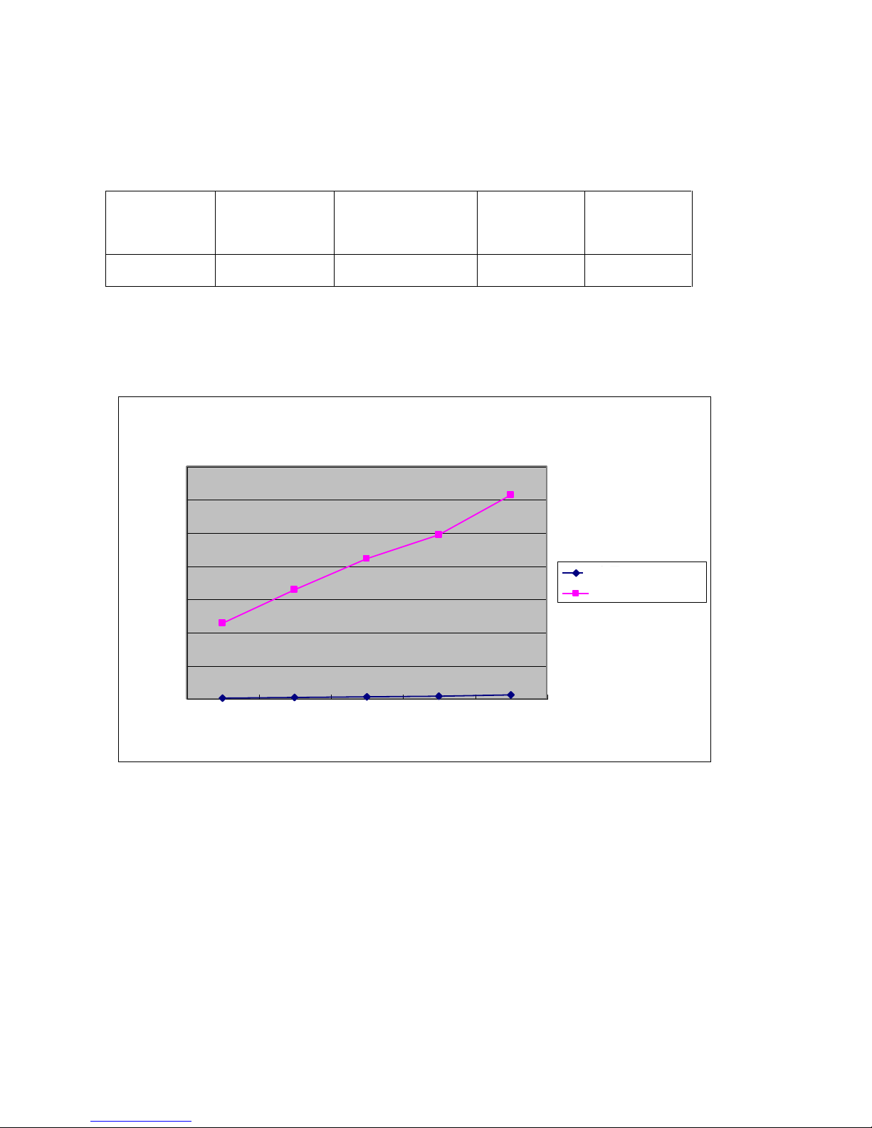
2. Pressure drop graph of one collector
Flow/pressure graph of one plate heat collector
0.01
0.019
0.029
0.038
0.058
1.14
1.64
2.11
2.47
3.07
0
0.5
1
1.5
2
2.5
3
3.5
1 2 3 4 5
流量(L/S)
压降(KPa)
流量(L/s·台)
压降(KPa)
The four major factors that impact the pressure drop of the collector are as following:
The quantity of the liquid flowing through the collector:When the diameter and the coarseness of the
draining pipe and collecting pipe for the collector is fixed, the pressure drop increases along with the
quantity increase of the liquid flowing through the collector.
The diameter of the draining pipe and collecting pipe for the collector:When the coarseness of the inner
wall of the pipe and the liquid quantity is fixed, the pressure drop increases along with the decrease of
the diameter.
The coarseness of the inner wall of the draining pipe and collecting pipe for the collector: When the
liquid quantity and pipe diameter is fixed, the pressure drop increases along with the increase of the
coarseness of the pipe’s inner wall.
The liquid viscosity: when other conditions are the same, the pressure drop increases along with the
viscosity increase of the liquid flowing in through the collector.
Flow
Pressure drop ()KPa)
Flow
Pressure drop ()KPa)
set
Page 4

4
3. The angle for mounting the collector
How to select the tilt angle α for mounting the collector:
When the solar system is applicable in four seasons: α=β
When the solar system is used mainly in summer: α=β-10
o
When the solar system is used mainly in winter: α=β+10o
Note: α——Title angle for mounting the collector;
β——Geographical latitude of the area for mounting the collector;
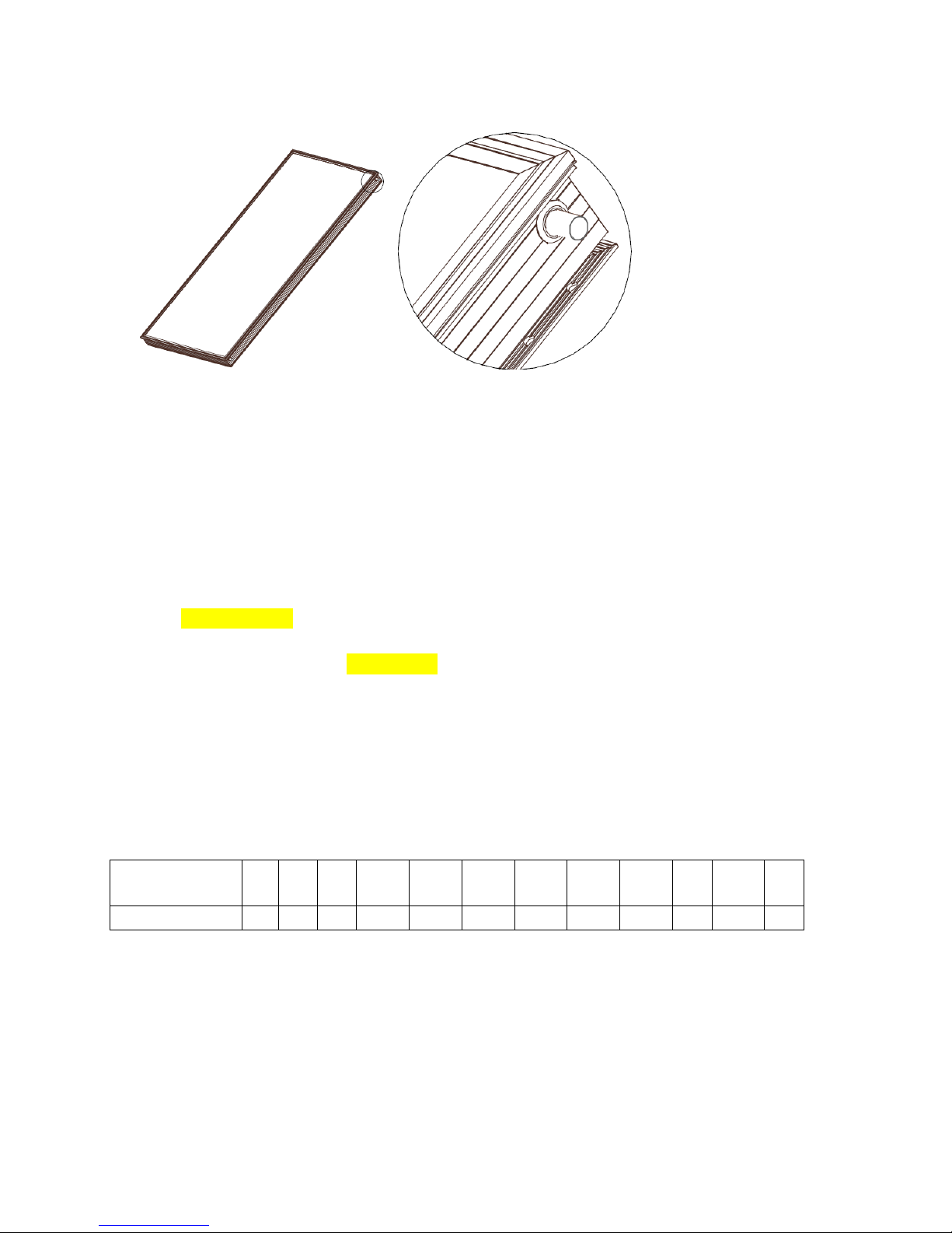
4. For the detailed sizes for mounting the plate collector, see the figure below(in: mm):
Page 5
5
The 16 holes (φ9) above are prepared for fixing the collector.
II. The introduction of the relevant heat conducting media of the plate heat collecting
system
It is the twice (secondary) circulation system that must be selected for the area where icing is possible. The
antifreeze shall be used in the heat conducting medium and propylene glycol is recommended to be used as the
antifreeze (It is forbidden to use the once (primary) circulation system in the area where icing is possible);
The secondary circulation system is recommended for the area where icing is impossible in any season and the
antifreeze could be used as the heat conducting medium. Pure water is recommended to conduct thermal energy.
The primary circulation system is not recommended;
The primary circulation system is not recommended to be used by the plate collector in any case; if it is inevitable
to use the primary circulation system, the problem with the scaling in of the copper pipe must be solved;
The table below contains the valves of the freeze points of the propylene glycol antifreezes which concentrations
are different. The concentration of the propylene glycol antifreeze to be filled in depends on the lowest
temperature of the application area. (It is for your reference only).
Concentration
(volume percent)
5
10
15
20
25
30
35
40
45
50
55
59
Freezing point ℃
-1.7
-3.3
-5.3
-7.2
-9.7
-12.8
-16.4
-20.9
-26.1
-32
-39.7
-50
The processes for filling liquid:
1. Inspect the pipes which have been connected to make sure that the check valve, gate valve, filter and circulation
pump are connected correctly, and that the pipes and connectors have been tightened while the pipes have been
fixed firmly (for the pipe connection, see the figure below);
Page 6

6
2. Pressurization test(Pressurizing with water):
接室内用水
平板集热器
储水箱
自来水
压力安全阀
膨胀罐
阀1
阀2
阀3
自动排气阀
过滤器
单向阀
过滤器
单向阀
循环泵
阀4
(Principle schematic drawing of the heat collecting system)
阀1
阀3
储液罐
注液泵
压力表
阀2
过滤器
膨胀罐
压力安全阀
单向阀
循环泵
(Schematic drawing for the liquid filling components)
Plate heat collector
automatic exhaust valve
valve 4
Valve3
Valve1
Valve2
Valve2
Valve2
Valve3
Valve1
Circulation pump
Check valve
expansion tank
water reservoir
Pressure relief valve
filter
Check valve
filter
Tap water
connecting to the water used indoor
Liquid tank
circulation pump
Check valve
Pressure relief valve
expansion tank
filter
Manometer
Liquid filling pump
Page 7

7
Open the automatic exhaust valve first and close the valve at the inlet of the expansion tank. Connect the outlet of
the liquid filling pump to valve 1 and ensure that the water flows in the same directions for mounting check valve.
Connect the suction nozzle of the pump and water-return pipe to the liquid filling tank. Close valve 2 and open the
valve below the highest automatic exhaust valve on the array of the collector. Allow the liquid filling pump to fill
water into the system. Observe the water flowing back and close the water return valve 3 (marking it) when you
find that the returned water is clean and flows evenly, and there are no more bubbles. Pressurize it at the pressure
which is 1.5 times the pressure for opening the relief valve. Observe the connection points carefully to find out if
there is any leakage or oozing. It passes the test when there is no leakage or oozing, and the pressure drop is less
than 0.02MPa in 10 minutes.
Attention:
a. The test pressure is 1.5 times of the pressure for opening the relief valve;
b. Notice the relative positions of the relief valve and manometer.
3. Pipe cleaning:
Pipes shall be cleaned before and after testing the pressure of the system by flushing them and cleaning the filter.
Then drain the liquid from the pipe so as to fill antifreeze; if the liquid is not drained up from the system, you can
blow the liquid out with a blower; blow it until it is dried up.
4. Antifreeze filling:
The process for filling antifreeze is same as the above. The different work is that the valve connecting to the
expansion tank must be opened before filling the antifreeze; it should also be noticed that the pressure for filling
the liquid must be consistent to pre-filling pressure of the expansion tank, 0.15MPa to 0.2MPa in general;
5. Close valve 4 below the automatic exhaust valve when antifreeze is fully filled to prevent the medium
vaporizing when the system operates;
Requirements on maintenance and notices:
1. If it will stay idle for long time, cover the plate collector with a nontransparent object and disconnect it from the
power supply to prevent overheating of the collector.
2. Check the system regularly to find out if it operates properly; check the manometer to look at if the pressure
valve on it is normal; if the pressure value is under standard, check if there is any leakage on the pipes; if not,
antifreeze shall be refilled into the system.
3. If the system needs the antifreeze to be replaced, it shall be emptied first. The liquids in the pipes shall be
drained up so as to fill antifreeze into it. If liquid cannot be drained up from the system, dry it by blowing the
system with a blower; don’t stop blowing until the system is completely dry(Attention, the replacement should be
assisted by the local after-service providers).
4. Check the low temperature resistibility of the antifreeze regularly(For the detailed interval, consult the local
antifreeze supplier).
5. Pull the lever of the relief valve monthly to flush the valve seat and valve clack; keep dirt and scaling off its
sealing surface since they would cause leakage or Open/Close failing. Check if the valve can be opened or closed
normally.
Page 8

8
III. Introduction of the lightning arrestor
Since collectors are mounted on roofs, they are vulnerable to lightning strikes. Therefore, they shall be mounted in
the area which is well protected against lightning. If there isn’t any lightning arrestor, to protect the plate collector,
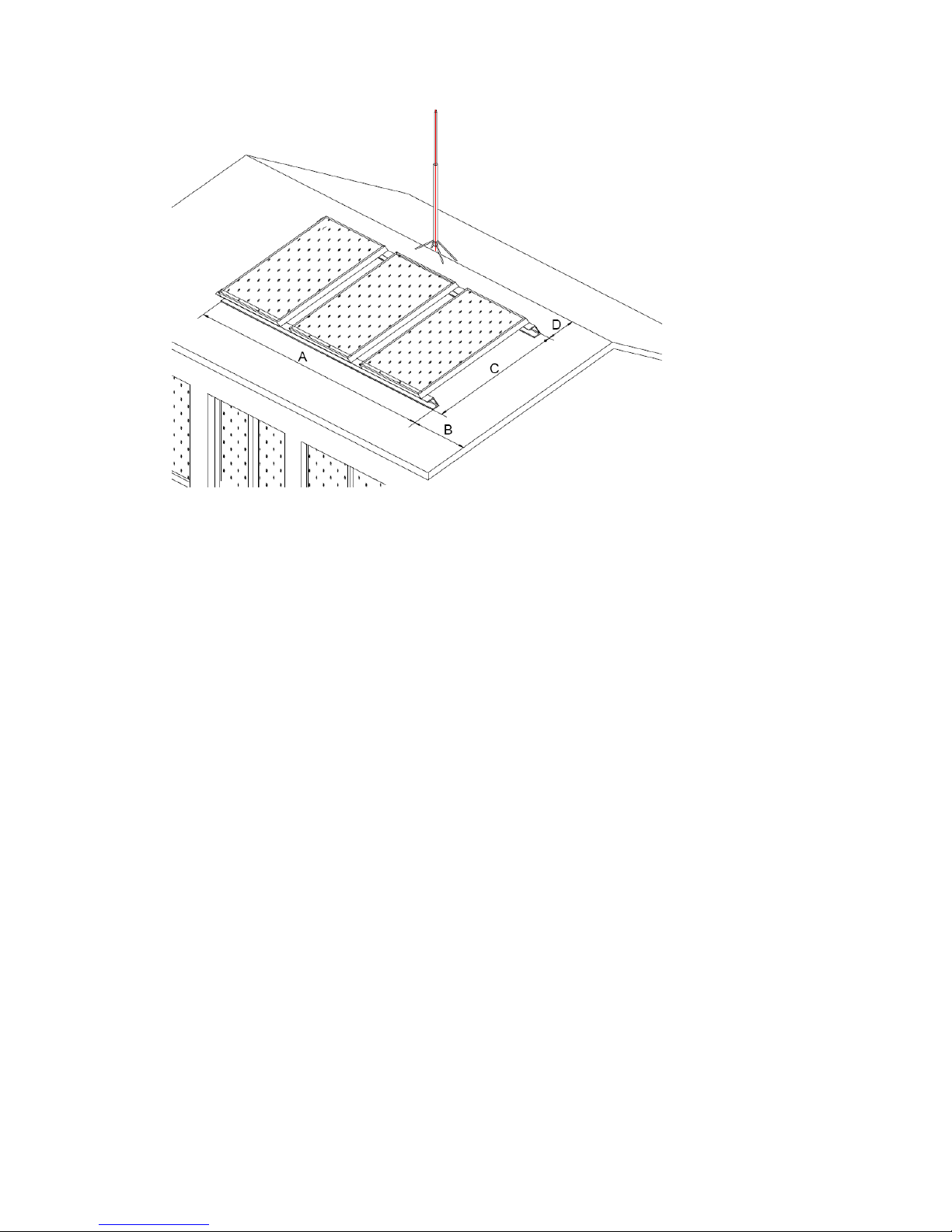
a lightning rod or grounding line is required. The following is a simple drawing for mounting the lightning rod on
a flat or sloped roof:
● The drawing for mounting the lightning rod on a flat roof:
The lightning rod can be welded onto a frame, or an independent lightning rod can be manufactured and it can be
fixed with a wire rope.
● The drawing for mounting the lightning rod on sloped roof:
Making an independent lightning rod is recommended; it can be fixed with a wire rope and the equipotential
bonding shall be applied between it, the frame and the lightning belt.
Lightning rod
Grounding line
Page 9
9
Notes:
1. If the building has a lightning arrestor, it shall be made sure by the local professional if the collector is well
protected by the lightning arrestor.
2. If the collector can be protected, the frame mounted on-site shall be connected to the existing lightning belt
with equipotential bonding. For the connection material, connection and anti-corrosion method, the local
specifications about the lightning system designing shall be followed.
3. If the collector cannot be protected, making a lightning rod is required; it shall be the relevant professionals that
decide how to select the materials, decides its height and how to fix it; the lightning rod and its frame mounted
on-site shall be connected to the existing lightning belt with equipotential bonding. For the connection material,
connection and anti-corrosion method, the local specifications about the lightning system designing shall be
followed.
IV. How to mount and fix the plate collector
Different ways to mount and fix the plate collector:
How to mount it on a sloped roof;
How to mount it on a flat roof;
How to mount it on a wall;
Page 10
10
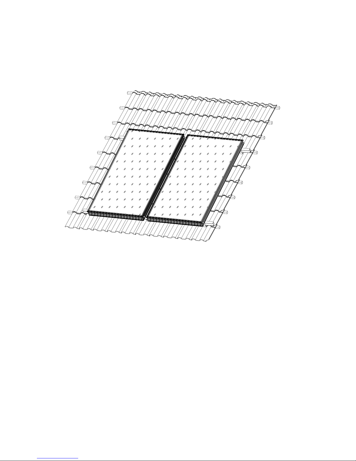
(I) There are two ways to mount the collector on a sloped roof, depending on the roof style:
How to mount it on a tile roof:
How to mount it on a color steel roof:
1. How to mount it on a tile roof:
(1) How to assemble the fittings of the plate collector
① How to connect and fix it with batten
Page 11

11
平板集热器
角钢件
L40*70*120*4
集数器连接件
固定螺栓M8 16
焊接
挂瓦条
Plate heat collector
Set bolt
Batten
Plate heat collector
connector
Welding
Angle iron piece
Page 12
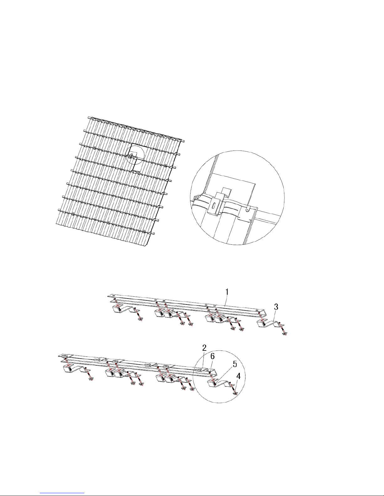
12
1:Channel steel 2:Collector fixing hook 3:Collector connector (There is a wrong mark in the
drawing) 4:Wood screw 5:Angle iron piece 6:Bolt 7:Nut
Step 1: Remove the tile from the place where the plate collector shall be mounted and fixed.
Step 2: Prepare angle iron pieces 5 (L40*70*120*4); fix them onto the roof beam with wood screw 4 after drilling
its side wall;
Step 3: Weld the bent collector connector 3 onto the angle iron piece 5 (they can be weld prior to mounting them);
Step 4: Connect the drilled channel steel 1with collector connector 3 with bolt 6.
② How to connect and fix the prepared bolt
Page 13
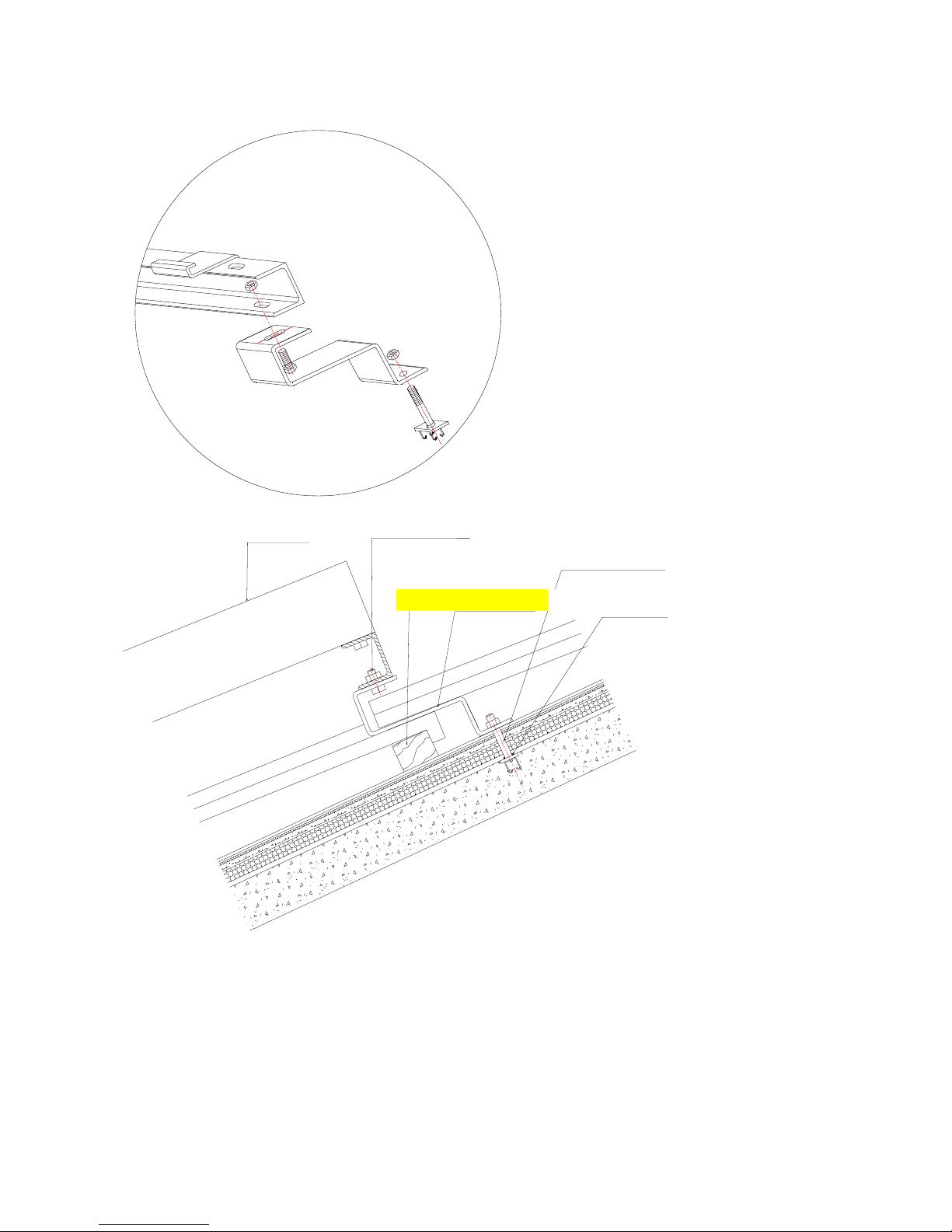
13
密封油膏
预留膨胀螺栓M12
固定螺栓M8 16
平板集热器
集数器连接件
挂瓦条
1:Channel steel 2:Collector fixing hook 3:Collector connector (There is a wrong mark in the drawing)
4:Prepared bolt 5:Bolt 6:Nut
Step 1: Build M12 bolt 4 onto roof with concrete;
If bolt 4 is not built in on the roof in advance, the collector can be fixed with an expansion bolt during mounting,
but waterproofing measures shall be taken.
Plate heat collector
Set bolt M8*16
Batten
Heat collector connector
Sealing grease
Prepared expansion bolt
Page 14

14
Step 2: Prepare the collector connector 3, drill holes on its bottom and fix it with bolt 4.
Step 3: Fix the drilled channel steel 1 and collector connector 3 with bolt 5.
(2)Put tile back to its original place when the collector connector is assembled.
(3)Fix the channel steel with collector connector with bolt 5, mount the collector fixing hook 2 onto the lower
channel steel, cushion them with rubber pad 4, mount plate collector 1 onto it, hook the lower edge of the plate
collector 1, fix the upper edge with the fixing hole on the outer frame, and connect plate collector and the fixed
channel steel with bolts.
Page 15

15
1:Plate collector 2:Collector fixing hook 3:Channel steel 4:Rubber pad
Page 16
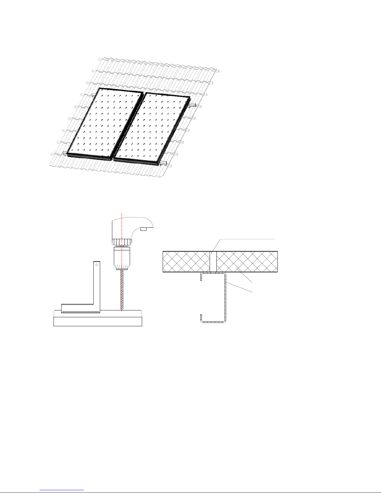
16
2. How to mount it onto color steel roof:
9
8
现场钻孔
Drilling hole on-site
Page 17
17
Page 18
18
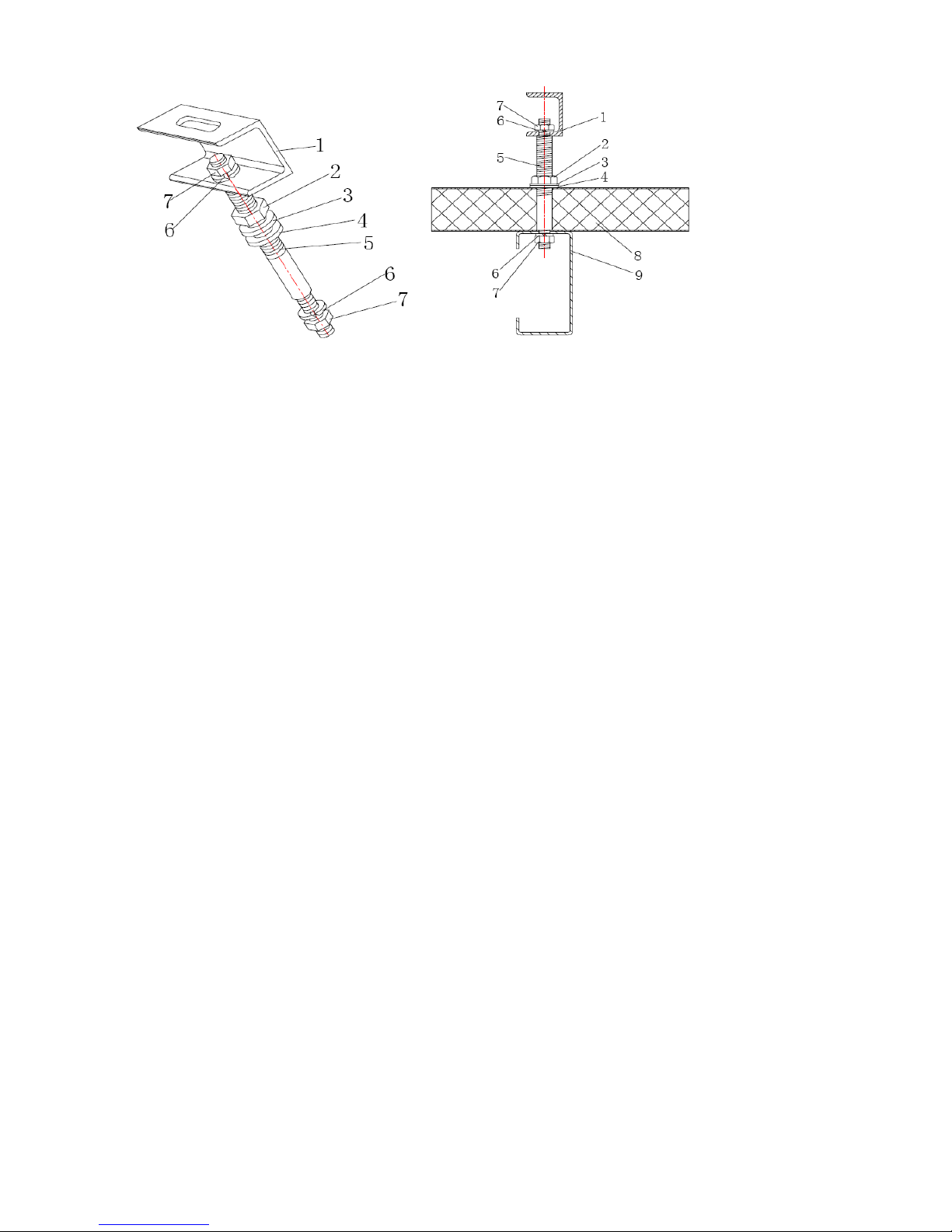
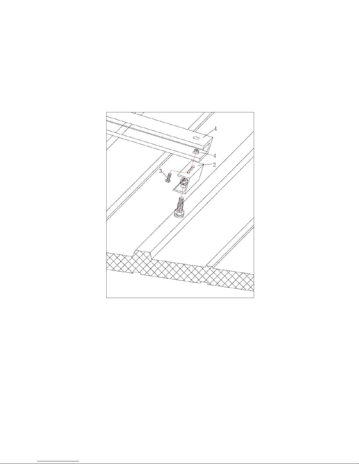
1:Channel steel connector 2:Nut 3:Gasket 4:Rubber gasket 5:Collector fixing Bolt
6:Spring shim 7:Nut 8:Color steel plate 9:C steel
Step 1:Drill holes on the color steel and C steel;
Step 2:Insert the collector fixing bolt into the holes drilled; assemble nut 7 and spring shim 6 in order and tighten
them; assemble nut2, gasket 3 and rubber gasket 4 in sequence with the collector fixing bolt 5; as it is just for
sealing, don’t make them too tight;
Step 3:Fix the channel steel connector to the collector fixing bolt 5.
1:Channel steel 2:Collector fastener 3:Bolt 4:Nut
Step 4: Prepare the hole-drilled channel steel, fix the collector fastener 2 with channel steel 1 with bolt 3 and nut 4;
screw them up.
Step 5: Fix the plate collector with the fixed channel steel with bolt through the fixing hole on the outer frame of
the plate collector.
Page 19
19
II. How to mount the collector on flat roof
1. How to prefabricate the foundation of the collector
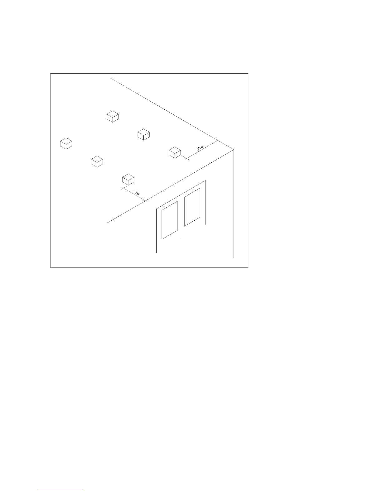
Select a proper foundation for the collector according to the actual roof condition, which may be a field casting
concrete frusta or concrete brick. No matter which way is taken, the top of the foundation for the collector shall be
leveled.
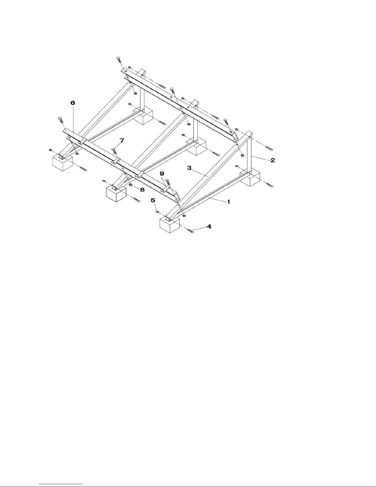
2. How to mount the support for the collector
(1)Mounting steps
Page 20
20
1: Bottom rod of the support 2: Vertical rod of the support 3: Tilted rod of the support 4 and 7: Bolt
5 and 8: Nut 6: Channel steel 9:Collector fixing hook
Step 1: Fix angle iron 1 onto the concrete foundation with expansion bolt;
Step 2: Make angle iron 2 and 3 a triangle frame with bolt 4 and nut 5;
Step 3: Fix the channel steel 6 not the triangle frame assembled in step 2 with bolt 7 and nut 8;
Step 4: Anti-corrosion treatment: When the support is finished, treat it with hot galvanizing or paint it to prevent
corrosion. First remove rust, oil or dirt off the angle iron and channel steel, apply the antirust paint on it twice and
apply finish paint twice.
Step 5: Mount the collector fixing hook 9 onto the lower channel steel and cushion them with a rubber pad.
(2)Assembling the finished support
Page 21

21
3. How to mount the plate collector
1: Plate collector 2:Collector fixing hook 3:Channel steel 4:Rubber pad
Page 22
22
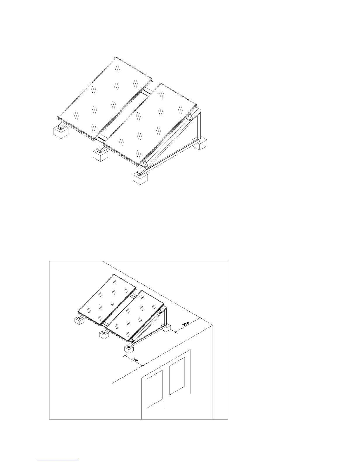
Step 1: Fix the collector onto the assembled support, clutch the lower edge of the collector with the collector
fixing hook; the upper edge of the collector shall be fixed through the fixing hole on its outer frame. Connect the
plate collector to the fixed channel steel with a bolt.
Step 2: Tighten all bolts.
4. Sample drawing for the mounted collector
Page 23

23
Page 24
24
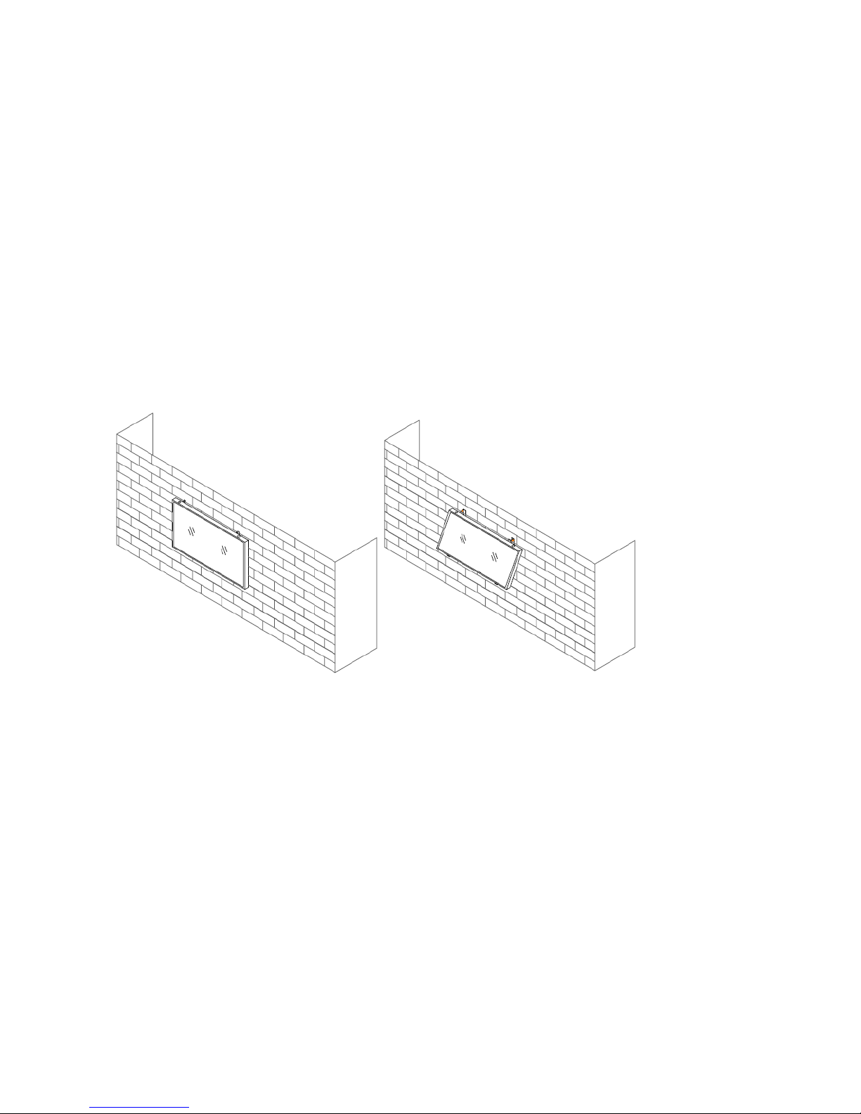
III. How to mount the collector on an external wall
The requirement to the wall body for mounting the collector on external wall:
The loadability of the external wall shall be 2 times the total mass of the collector loaded fully with water and
there shouldn’t be any deformation, crack or chip on the wall body. Its loadability shall be confirmed through
tests. In addition to its loadability to the solar collector, the necessary technical measures shall be taken to
treat the locations where the collector will be mounted, so as to prevent the disadvantages to the wall body,
such as deforming or cracks, etc.
The light-weight filled wall shall not be used as a structure to support the solar collector.
The support of the collector mounted on the external wall shall be fixed onto the built-in connector in the
wall firmly. A concrete structural column could be added at the place o the built-in connector if necessary,
and it shall meet the requirement of anticorrosion.
There are two ways for mounting the plate collector onto the external wall, depending on the angle between
the plate collector and the external wall.
● Mount the plate collector onto the wall vertically;
● Mount the plate collector onto the wall not vertically;
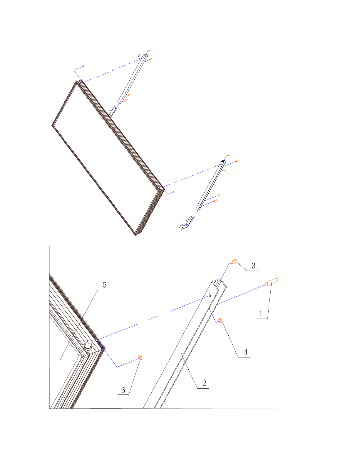
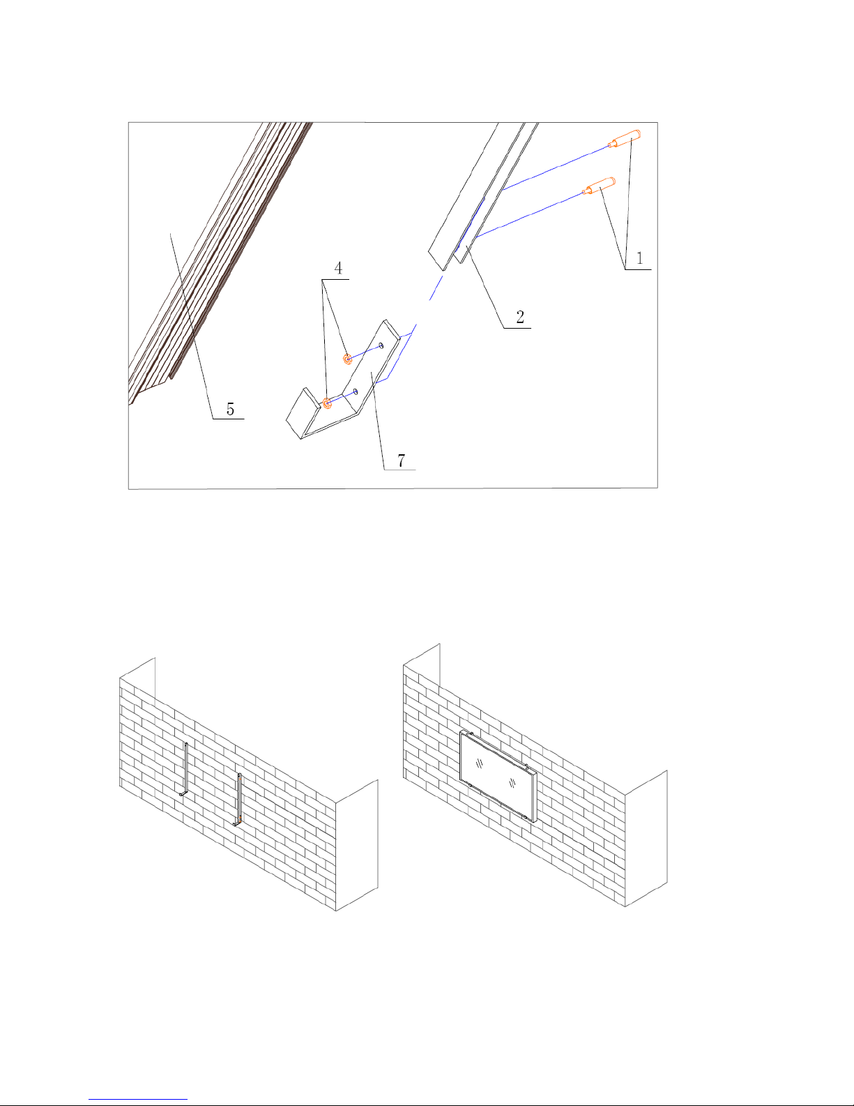
1. When the plate collector is mounted to the external wall vertically:
Page 25
25
Page 26
26
1: Expansion bolt 2: Channel steel 3: Bolt 4、6: Nut 5: Plate collector 7: Collector fixing
hook
Step 1: Drill 3 holes on the external wall and insert the expansion bolt 1 into the holes;
Step 2: After drilling holes on the channel steel 2, fix the channel steel 2 and collector fixing hook 7 onto the
external wall with expansion bolt 1 and nut 4.
Step 3: Put the plate collector onto the collector fixing hook 7 and stabilize; Fix the plate collector 5 onto the
channel steel 2 with bolt 3 and nut 6 through the fixing holes on the outer frame of the plate collector.
Page 27
27
平板集热器
M8螺栓
M8膨胀螺栓
5号槽钢
I
平板集热器
M8螺栓
M8膨胀螺栓
5号槽钢
I
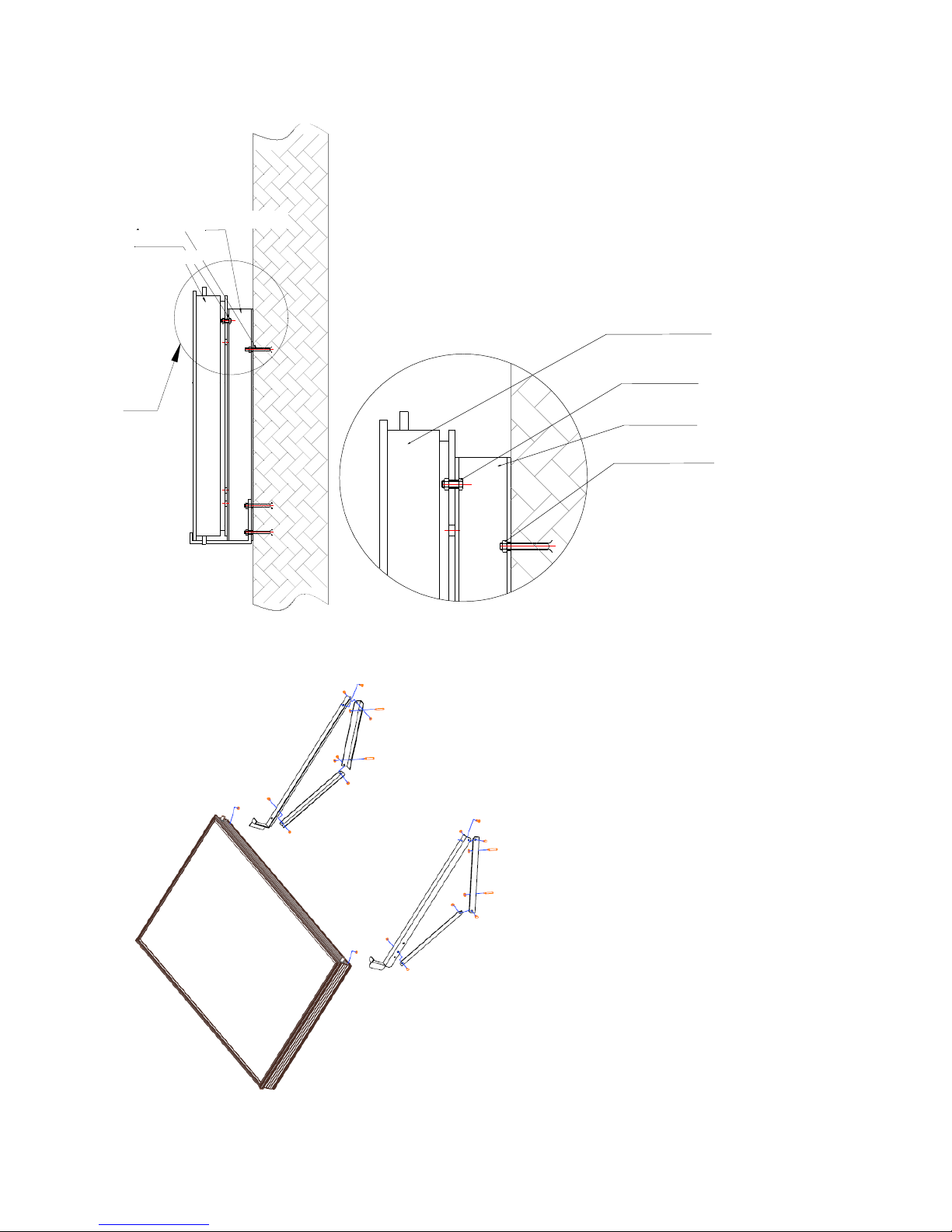
2. When the plate collector is mounted to the external wall not vertically
M8 expansion bolt
#5 Channel steel
Plate heat collector
Plate heat collector
M8 expansion bolt
M8 expansion bolt
M8 bolt
#5 Channel steel
Page 28
28
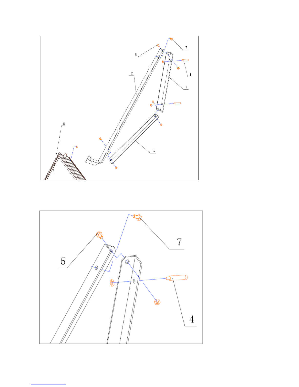
1: Support frame 2: Front support 3: Support connecting rod 4: Expansion bolt 5:Bolt
6: Plate collector 7: Bolt
Page 29
29
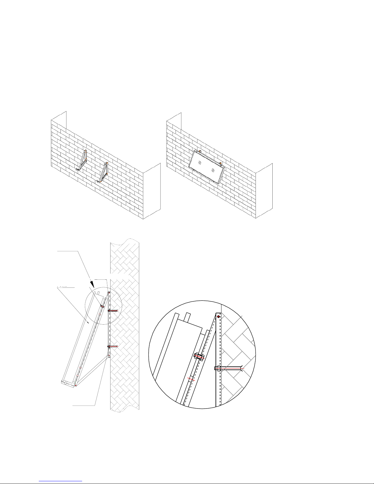
Step 1: Make support 1, 2 and 3 of the collector with angle steel as per the drawing above and assemble support 1,
2 and 3 with bolt 5; tighten and fix them;
Step 2: Drill holes on the external wall and insert expansion bolt 4 into the holes;
Step 3: Fix the support which has been assembled in step 1 onto the external wall;
Step 4: Put the plate collector 6 onto the support and connect the plate collector 6 with the fixed support with bolt
7 through the outer frame of the plate collector.
平板集热器
M8螺栓
M8膨胀螺栓
角钢支架
I
I
Angle iron support
M8 bolt
plate heat collector
M8 expansion bolt
Page 30
30
V. Introduction of how to mount pipes for the plate collector
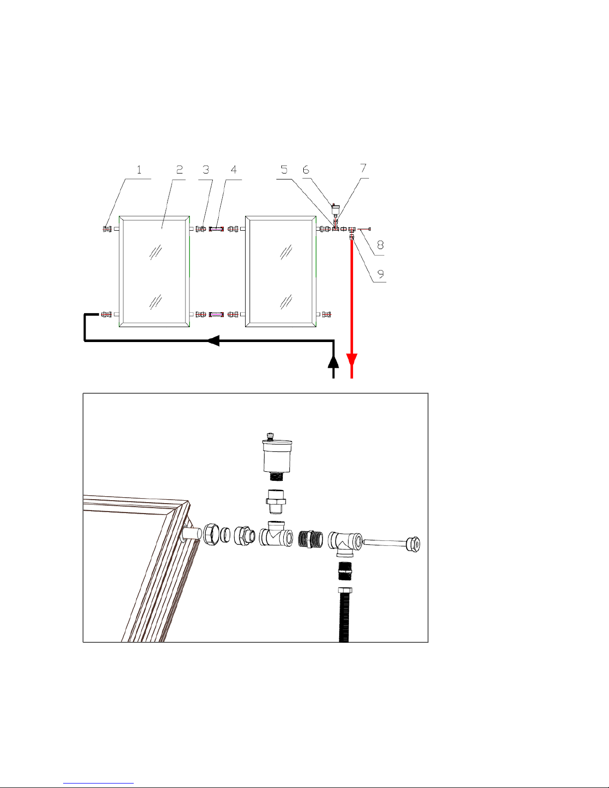
1. How to connect two plate collectors
There are two ways to connect two plate collectors next to each other. Such mounting ways can ensure that the
pipe distance in the system is equal and can shorten the hot water circulation pile, which can reduce the thermal
loss from the pipe and increase the heat collecting efficiency of the solar system.
The 1st Method:
Page 31
31
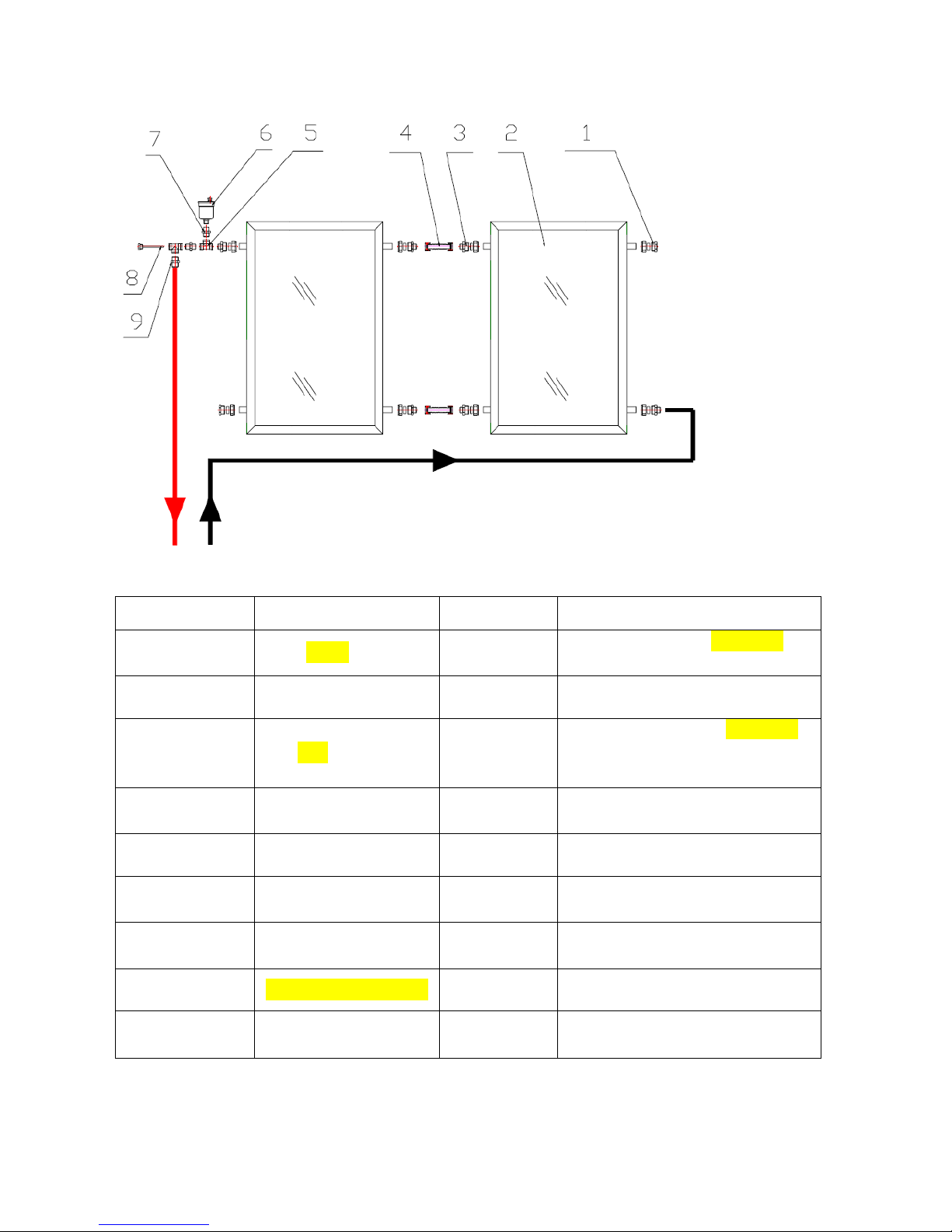
The 2nd Method:
No.
Name
Qty
Specification
1
卡套 Stopper
2 sets
Connect one end to the copper pipe(¢
22) and the other end is a G3/4 stopper
2
Plate collector
2
1998*1024*80(mm)
3
卡套 connector
6 sets
Connect one end to the copper pipe
(¢22) and another end interface is
G1/2 male thread
4
Bellows
2
200mm long; and two end interfaces are
G1/2 female thread nut
5
Tee-joint
2
G1/2 female thread to three directions
6
Automatic exhausting
valve(Caleffi)
1
G3/8 male thread for the lower end
7
Taper joint
1
G3/8 female thread for the upper end
and G1/2 male thread for the lower end
8
测温盲管 (Thermometer)
1
G1/2 male thread for one end
9
Double nipple
2
G1/2 male thread for two ends
Page 32
32
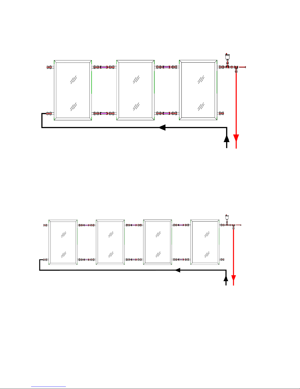
2. How to connect 3 plate collectors:
To mount 3 plate collectors, the pipelines can be adjusted left and right according to the actual site conditions. The
pipes and fittings shall be mounted in the same way for mounting two collectors above.
3. How to connect 4 plate collectors:
The 1st Method:
Get 4 plate collectors in one row and mount them; this mounting way needs a mounting area big enough.
Page 33
33
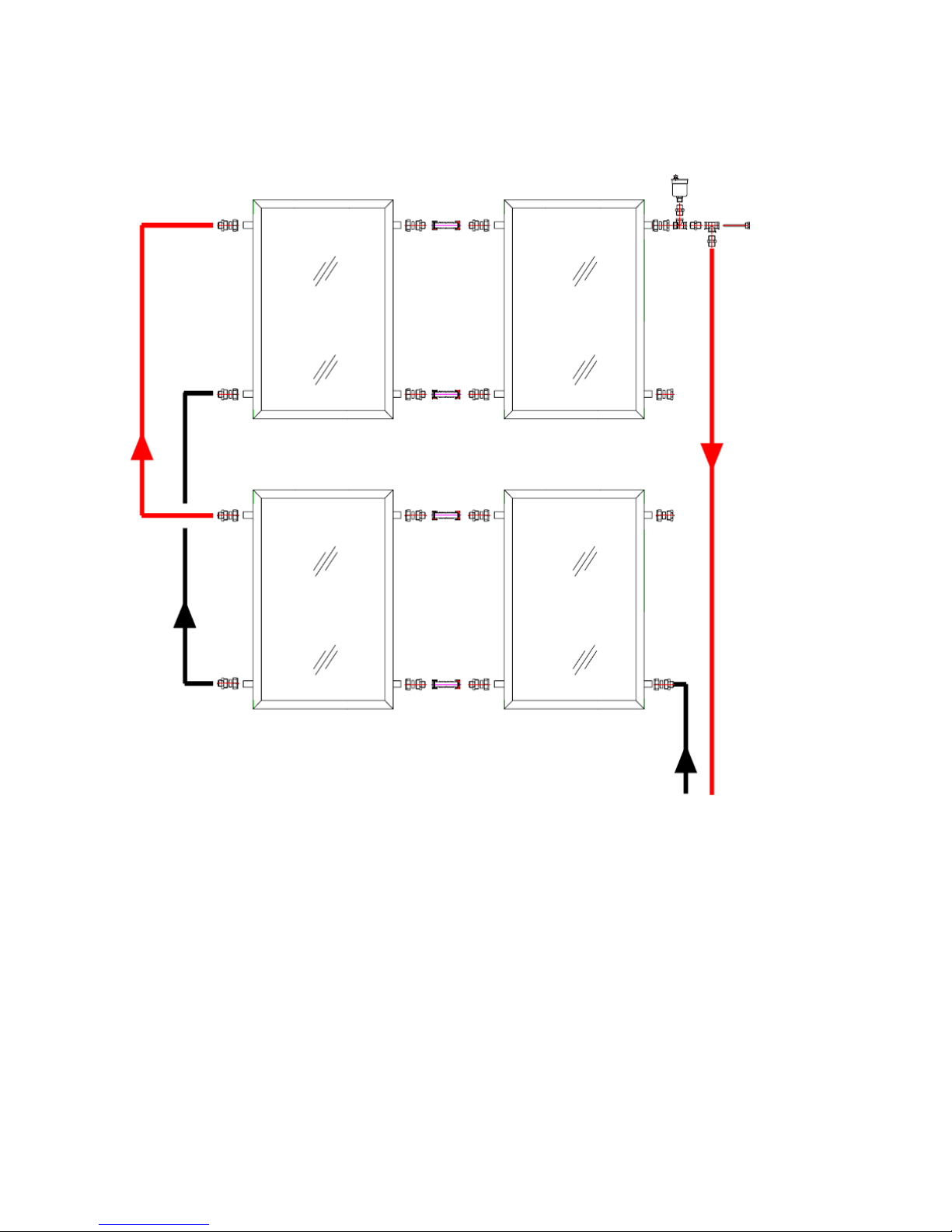
The 2nd Method:
If the mounting area is limited, the collector array may be mounted in the following way. For this kind of array of
collectors, 4 plate collectors shall be connected in parallel too and they are not put in one row. The pipes and
fittings shall be mounted in the same way as mounting two collectors above.
Page 34
34
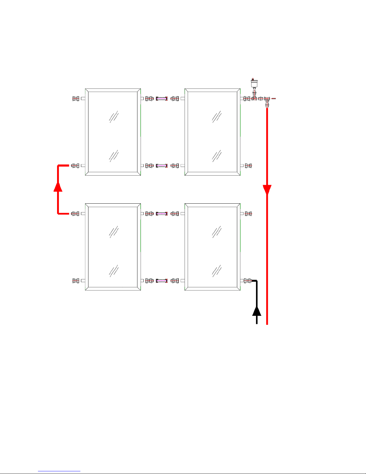
The 3rd Method:
The kind of array of the collector needs less mounting area, but first two collectors shall be connected in parallel
and then assemble two sets of the connected collectors in parallel too. The pipes and fittings shall be mounted in
the same way for mounting two collectors above.
Page 35
35
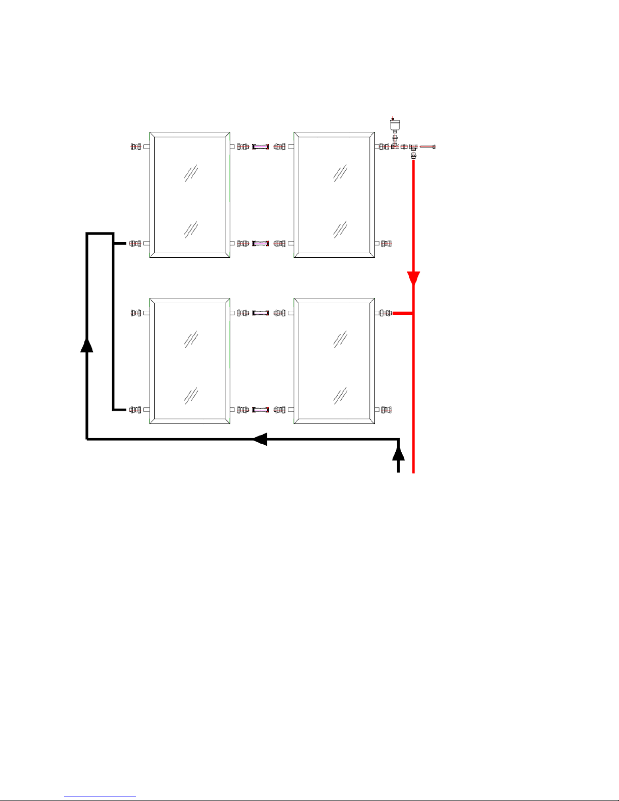
The 4th Method:
The kind of array of the collector needs less mounting area. To connect the collectors, connect two of them in
parallel first and then assemble two sets of the connected collectors in parallel. The pipes and fittings shall be
mounted in the same way for mounting the collectors above.
Notes:
To mount multiple plate collectors in a serial or parallel way, the above array way can be taken as an
example.
When more than 4 plate collectors are going to be mounted on a row, the serial mounting is not
recommended, i.e. the 3rd mounting method shouldn’t be used since this kind of connection has larger
resistance drop. The 1st, 2nd or 4th method is recommended.
It is recommended that at most 8 plate collectors are going to be mounted in one row when they are mounted
in parallel, i.e. when they are to be mounted in parallel, the 4th method should be chosen.
 Loading...