


PLASMA TV
OWNER`S MANUAL
MODEL : P50V6-A8S
Please READ this manual carefully before
operating your TV, and retain it for future
reference.
Congratulations on your purchase, and welcome to the family !
Dear Haier product owner:
Thank you for your confidence in Haier. You`ve selected one of the
best-built, best-backed products available today. We`ll do everything
in our power to keep you happy with your purchase for many years to
come.
As a member of the Haier family, you`re entitled to protection by
one of the most comprehensive warranties and outstanding service
networks in the industry.
thanks for investing in a Haier product.
""
""
Warning
WARNING
RISK OF ELECTRIC SHOOK
DO NOT OPEN
WARNING : To reduce the risk of electric shock do not remove
cover or back. No user-serviceable parts inside refer service
to qualified service personnel.
Safety of operators has been taken into consideration at the design and
manufacture phase, but inappropriate operation may cause electric shock
or fire. To prevent the product from being damaged, the following rules
should be observed for the installation, use and maintenance of th product.
Read the following safety instruction before starting the operation.
The User Manual uses the following symbols to ensure a safe operation
and prevent any damage to operators or properties:
This symbol indicates that high voltage is present inside. It is
dangerous to make any kind of contact with any inside part of
this product.
This symbol indicates that there are important operating and
maintenance instructions in the literature accompanying the
appliance.

Important Safety Instructions
Important safeguards for you and your new product
Your product has been manufactured and tested with your safety in mind. However, improper
use can result in electrical shock or fire hazards. To avoid defeating the safeguards that have
been built into your new product, please read and observe the following safety points when
installing and using your new product, and save them for future reference.
1. Retain these Instructions ---the safety and operating instructions should be retained for
Future reference.
2. Heed Warnings ---All warning on the appliance and in the operating instructions should be
followed.
3.Cleaning --- Unplug from the wall outlet before cleaning. Do not use liquid cleaners or
Aerosol cleaners. Use only dry cloth for cleaning.
4. Attachments ---do not use attachments
not recommended by the manufacturer as they may cause Hazards.
5. Water and moisture -- do not place this product near water, for example, near a bathtub,
wash bowl, kitchen sink, laundry tub, in a wet basement, or near a swimming pool.
6. Do not place this unit on an unstable cart, stand, tripod, bracket, or table. Use
only with a cart, stand, tripod, bracket, or table recommend by the manufacture, or sold with
the unit.
7. Ventilation ---Slots and openings in the cabinets and the back or bottom are provided for
Ventilation and to ensure reliable operation of the product and to protect it from overheating,
and these openings must not be blocked or covered. The openings should never be
blocked by placing the product on a bed, sofa, rug, or other similar surface. This product
should not be placed in a built-in installation such as a bookcase or rack unless proper
ventilation is provided or the manufacturer`s instructions have been adhered to.
8. Power Source ---this unit should be operated only from the type of power source indicated on
the rating label. If you are not sure of the type of power supply to your home, consult your
Appliance dealer or local power company.
9. Do not defeat the safety purpose of the polarized or
Grounding or polarization ---
grounding-type plug. A polarized plug has two blades with one wider than the other. A
grounding type plug has two blades and a third grounding prong. The wide blade or the third
prong are provided for your safety. If the provided plug does not fit into your outlet, consult an
electrician for replacement of the obsolete outlet. To prevent electric shock, ensure the
Grounding pin on the AC cord power plug is securely connected.
10. Power cord protection ---Power supply cords should be routed so that they are not likely to
Be walked on or pinched by items placed upon or against them. Pay particular attention to
cords or plugs, convenience receptacle, and the point where they exit from the appliance.
11. Lighting precaution ---for added protection for this product during a lighting storm or when
it is left unattended for long period of time, unplug it from the wall outlet and disconnect the
antenna or cable system. This will prevent damage to the product due to lighting and
power line surges.
12. Never push objects of any kind into this product through openings as they may touch
dangerous voltage point or short out parts that could result in a fire or electric shock. Avoid
spilling liquid of any kind on the product.
13. Servicing ---do not attempt to service the product by yourself, as opening or removing
covers may expose you to dangerous voltage or other hazards. Refer all servicing to
authorized service personnel.
14.Damage Requiring Service ---Unplug this unit from the wall outlet and refer servicing to
Important Safety Instructions
qualified service personnel under the Following conditions:
a. When the power supply cord or plug is damaged or frayed.
b. If liquid has been spilled, or objects have been fallen into the unit.
c. If the unit has been exposed to rain or water.
D. If the unit does not operate normally by following the operating instructions. Adjust only
those controls that are covered by the operating instructions, as improper adjustment of
other controls may result in damage and will often require extensive work by a qualified
technician to restore the unit to its normal operation.
E. If the unit has been dropped or damaged in any way.
F. When the unit exhibits a distinct change in performance; this indicates a need for service.
15.Heat --- The product should be situated away heat source such as radiators, heat registers,
stoves, or other products (Including amplifiers) that product heat.
16.Overloading ---Do not overload wall outlets and extension cord as this can result in a risk of
Fire or Electric shock.
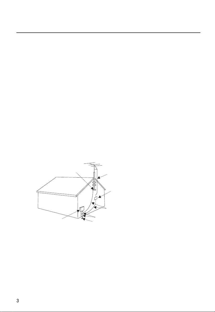
17. Outdoor antenna grounding---If an outside antenna or cable system is connected to
the unit, be sure the antenna or cable system is grounded to provide some protection
against voltage surges and built-up static charges, Section 810 of the National Electrical
Code, ANSI/NFPA 70, provides information with respect to proper grounding of the mast and
supporting structure, grounding of the lead-in wire to an antenna discharge unit, size of
grounding conductors, location of antenna discharge unit, connection to grounding
electrodes, and requirements for the grounding electrode.
GROUND CLAMP
ELECTRIC SERVICE EQUIPMENT
ANTENNA LEAD IN WIRE
ANTENNA DISCHARGE UNIT
(NEC SECTION 810-20)
GROUNDING CONDUCTORS
(NEC SECTION 810-21)
GROUND CLAMPS
POWER SERVICE GROUNDING ELECTRODE SYSTEM
(NEC ART 250, PART H )
Note: The PDP Manufacturing Process: a few minute colored dots may be
present on the PDP screen
The PDP (Plasma Display Panel), which is the display device of this
product is composed of 0.9 to 2.2 million cells. A few cell defects will normally
occur in the PDP manufacturing process. Several tiny, minute colored dots
visible on the screen should be acceptable. This also occurs in other PDP
manufacturers' products. The tiny dots appearing does not mean that this
PDP is defective. Thus a few cell defects are not sufficient cause for the PDP
to be exchanged or returned. Our production technology minimizes these cell
defects during the manufacture and operation of this product.
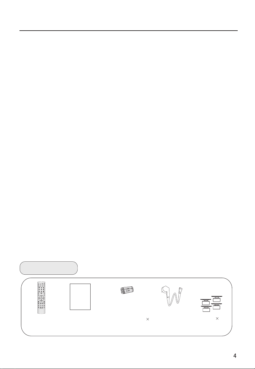
Table of Contents
Warning
............................................1
Important Safety Instructions...............2
buttons and interface location.............5
Front control panel
...........................5
Rear control panel.......
.....................6
Installation Instructions ......................7
Remote controller
Keys of remote controller
Function introduction
Effective range
...............................8
.....................9
.......................9
..............................10
External Equipment Connections .......11
Operation
Set up your TV..................................16
Switching ON/OFF the TV set..........16
Choose the Menu Language...........16
Select input modes ..........................17
Tuning menu
Automatic search.....................
......18
Program Table
Manual ............................20
....................................18
.......
......................19
search..
Fine Tuning...................................21
How to select the desired program.....22
Edit Name
Skip
.....................................23
..............................................24
Program swap...............................24
Picture menu
How to select picture modes
...................................25
............25
Noise Reduction .....................................26
Sound menu..............................................27
To choose sound modes ..........................27
Balance..................................................27
Setting Five Equalizer sound
...................28
Setting the surround sound ......................28
Setting the Auto Volume
How to eliminate sound
Timer menu
Timer setting
...............................................30
..........................................30
...........................29
...........................29
On/off time\Timer on Prog\Timer Prog ......31
Function menu..........................................32
Function setup .......................................32
Adjust menu .............................................34
To choose picture aspect ratio..................34
H-Position and V-Position adjust ..............35
RGB/Default/Auto Sync ..........................36
Color Temperature .................................36
Black Stretch .........................................36
Lock setup................................................37
Other functions.........................................40
Teletext functions......................................42
Maintenance.............................................44
Specifications and functions
Troubleshooting
........................................46
.......................45
Accessories
STILLSTILL
MUTEMUTE
DISPLAYDISPLAY
SLEEPSLEEP PIPPIP
SCANSCAN
ABC@ABC@
DEFDEF
GHI$GHI$ MNOMNO
JKL%JKL%
STUVSTUVPOR&POR& WXYZWXYZ
*#()*#()
TV/AVTV/AV
SWAPSWAP
P.STDP.STD S.STDS.STD
CH+CH+
VOL-VOL-
MENUMENU
VOL+VOL+
CH-CH-
H.LOCKH.LOCK
CH.LISTCH.LIST EXITEXIT
TIMERTIMER ZOOMZOOM
Remote controller
User's manual
Alkaline battery(AA) 2
Power cable
Bracket 4
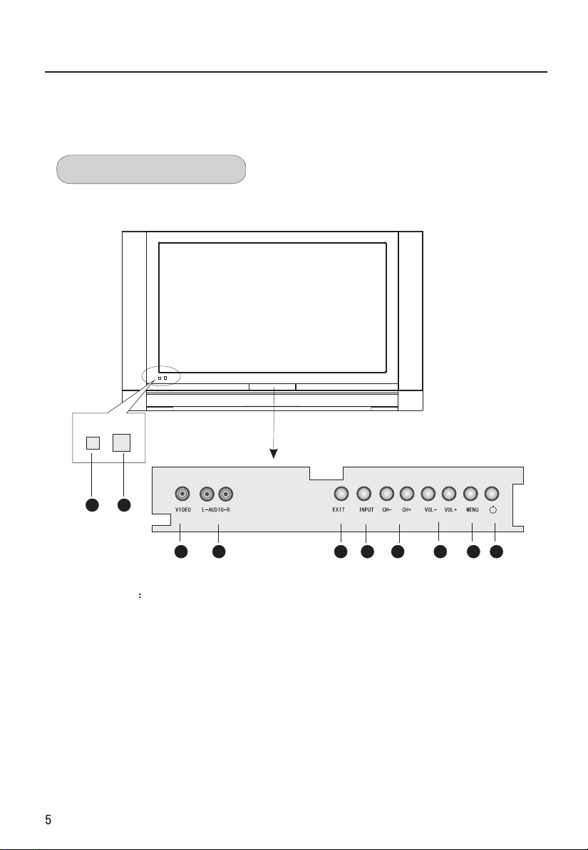
Buttons and interface location
-This is a simplified representation of front panel.
-Here shown may be somewhat different from your TV.
Front control panel
9
10
2
1
1.VIDEO input
2.L-AUDIO-R left and right audio input.
3. EXIT: clears all on-screen displays and returns to TV viewing from any menu.
4. INPUT: Source input select
5.CH- /CH+: Program plus and minus, menu options.
6. VOL-/VOL+: Volume increase and decrease, menu reset and entry
7.MENU: Menu display
8.Power
9.Remote control signal receive window.
10. Remote Indicator
In red when standby mode, in blue when display.
4
3
6
5
7 8
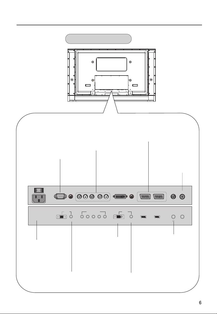
Buttons and interface location
Rear Control panel
PC VIDEO Input
Connect the monitor
output connector from
a PC to the jack
SWITCH
AC-INPUT
Power Cord Socket
This TV operates on
AC power.
The voltage is indicated
on the specifications page.
Never attempt to operate the
TV on DC power
VGA
DVD/DTV Input
(Component )
Connect a component
video/audiodevice to
these jacks.
VGA IN COMPONENT IN
AUDIO
Pr/Cr Pb/Cb Y L-AUDIO-R
DVI Input
Connect the monitor
output connector from
a PC to the appropriate
input port.
Audio input
for linking PC audio
frequency output terminals.
SCART2/SCART1 Input
Connect Scart out from
an Scart device to the
Scart input.
DVI IN
AUDIO
SCART2 SCART1
DVI
Earphone audio output
Audio input
for linking DVI audio
frequency output terminals.
Antenna Input
Connect cable or
antenna signals to
the TV, either directly
or through your
cable box.
ANT IN
Earphone jack:
terminal.
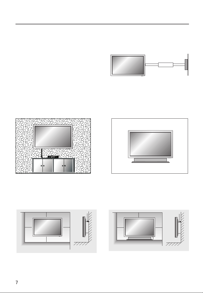
Installation Instructions
- The TV can be installed in various ways such as on a wall, or on a desktop etc.
- The TV is designed to be mounted horizontally.
GROUNDING
Ensure that you connect the earth ground
wire to prevent possible electric shock. If
grounding methods are not possible, have a
qualified electrician install a separate circuit
breaker. Do not try to ground the unit by
connecting it to telephone wires, lightening
rods, or gas pipes.
Wall Mount: Horizontal installation
For proper ventilation, allow a clearance of
""
4 on each side and 2 from the wall.
Detailed installation instructions are
available from your dealer, see the
optional Wall Mounting Bracket Installation.
Power
Supply
Short-circuit
Breaker
Desktop Pedestal Installation
For proper ventilation, allow a clearance
""
of 4 on each side and the top, 2.36 on
the bottom, and 2 from the wall. Detailed
"
installation instructions are included in
the optional Desktop Stand Installation.
4 inches
4 inches 4 inches
4 inches
2 inches
4 inches
4 inches 4 inches
2.36 inches
2 inches
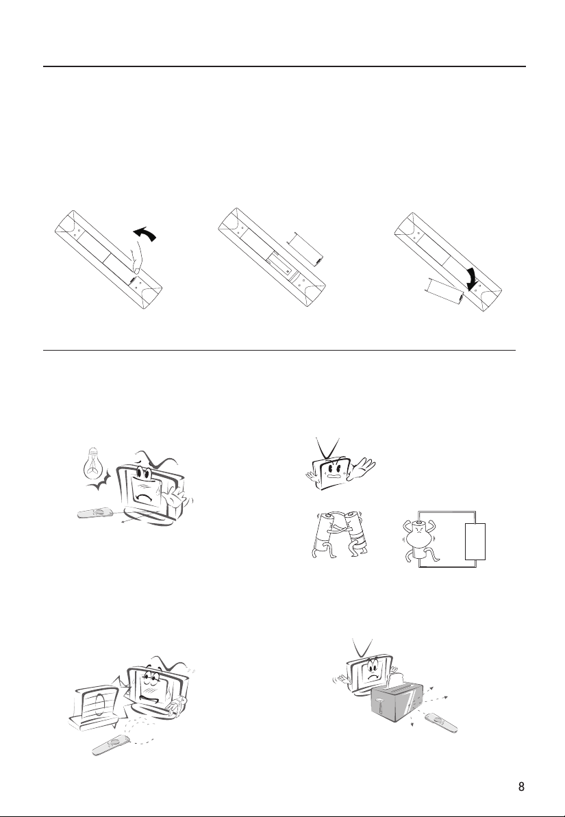
Remote controller
Inserting Batteries
1.Slide open the
cover of the battery
compartment on the
back of the remote
controller.
Precautions
2.Load two AA alkaline
batteries in the compartment.
paying attention to the polarity
diagram in the battery
compartment.
poles to respective mark)
(plus and minus
3.Replace the cover of the
battery compartment.
As strong light may interfere the
signals, change your position to
operate the remote controller if
the television cannot be turned
on or off as you expect.
Keep the remote controller away from
heat source or humid area to ensure
effective performance of the remote
controller.
Make sure that two AA alkaline batteries
are loaded. The batteries must be of the
same type. The batteries must be located
properly. The batteries are not
rechargeable.
Make sure that there is no obstacle between
the remote controller and television set.
4
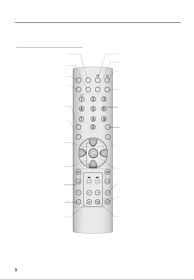
Keys of remote controller
- The remote controller cannot be operated unless the batteries are properly loaded.
- When using the remote control, aim it at the remote control sensor on the TV.
Function introduction
Picture static
STILL
SlEEP
Displaying sleep time,
adjustable
Switches the sound on or off
Program scan button
Input source display
MUTE
SCAN
TV/AV
P.STD
(Picture mode option)
sound increase
and decrease
STILL
MUTE
ABC@
JKL%
STUVPOR& WXYZ
*#()
CH+
MENU
VOL+
DISPLAY
DEF
SWAP
SLEEP PIP
SCAN
GHI$ MNO
TV/AV
P.STD S.STD
VOL-
I/II (NICAM)
PIP(No available)
Power OFF/Standby
any other programmed
equipment off.
DISPLAY
Display ON/OFF
Digits
Program direct option(when edit
program, every press can set
different sign by turns among the
digits and sign on top of them)
SWAP
Switch the current channel to the
last channel you have viewed.
S.STD
(Sound mode option)
Program up and down
Or turns your TV
Teletext buttons
buttons which have letters
on top also can use in TV.
Channel list button
Timer
Time display(only when
there is teletext in TV)
CH-
H.LOCK
CH.LIST EXIT
TIMER ZOOM
MENU
main menu entry, menu exit or
return to next higher level menu.
Lock button
(enter the Lock Set menu)
EXIT
clears all on-screen displays and
returns to TV viewing from any menu.
ZOOM
Adjust picture aspect ratio
Remote controller
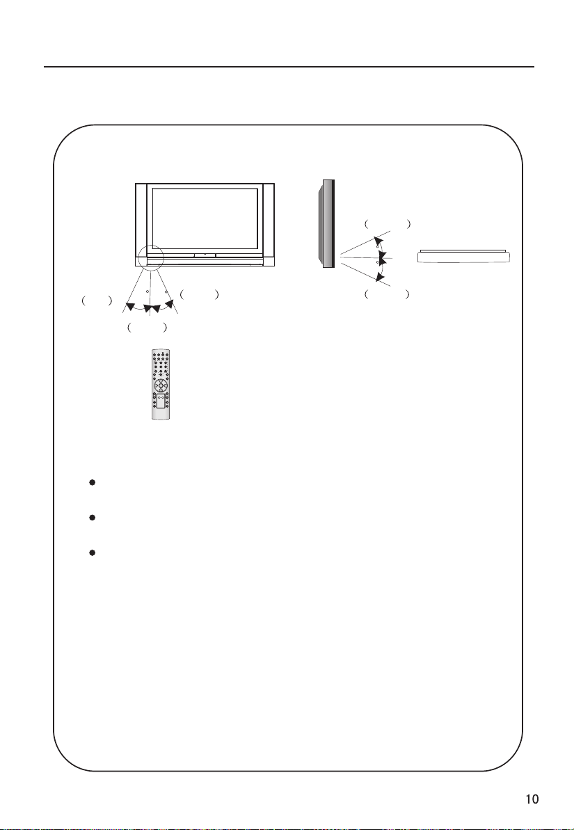
Effective range
above
20
20
left
45
45
right
below
front 8m
POWER
DISPLAY
FAV.
USB
-/--/---
Q.VIEW SLEEP
PSM
SSM
TV/AV MUTE
CH+
VOL-
MENU
VOL+
CH-
UP LEFT
H.LOCK
PREV.
DOWN
NEXT
PAUSE ENTER
SWAP EXIT
Ensure the remote controller is pointed toward the remote
controller window on the display.
No obstacle should be placed between the remote controller and
the remote controller window.
The effective receiving scope for the signal is 8 meters to the
front of the remote controller windows, and 45 to the left or right
side and 20 above or below the control window.
O
O
Use of remote controller:
1. To ensure a normal operation, the remote controller should not
be dropped or damaged in any way .
It should also be kept dry and away from all heat sources.
2. Battery replacement is necessary when the remote controller
acts inconsistently or stops operating the plasma display.
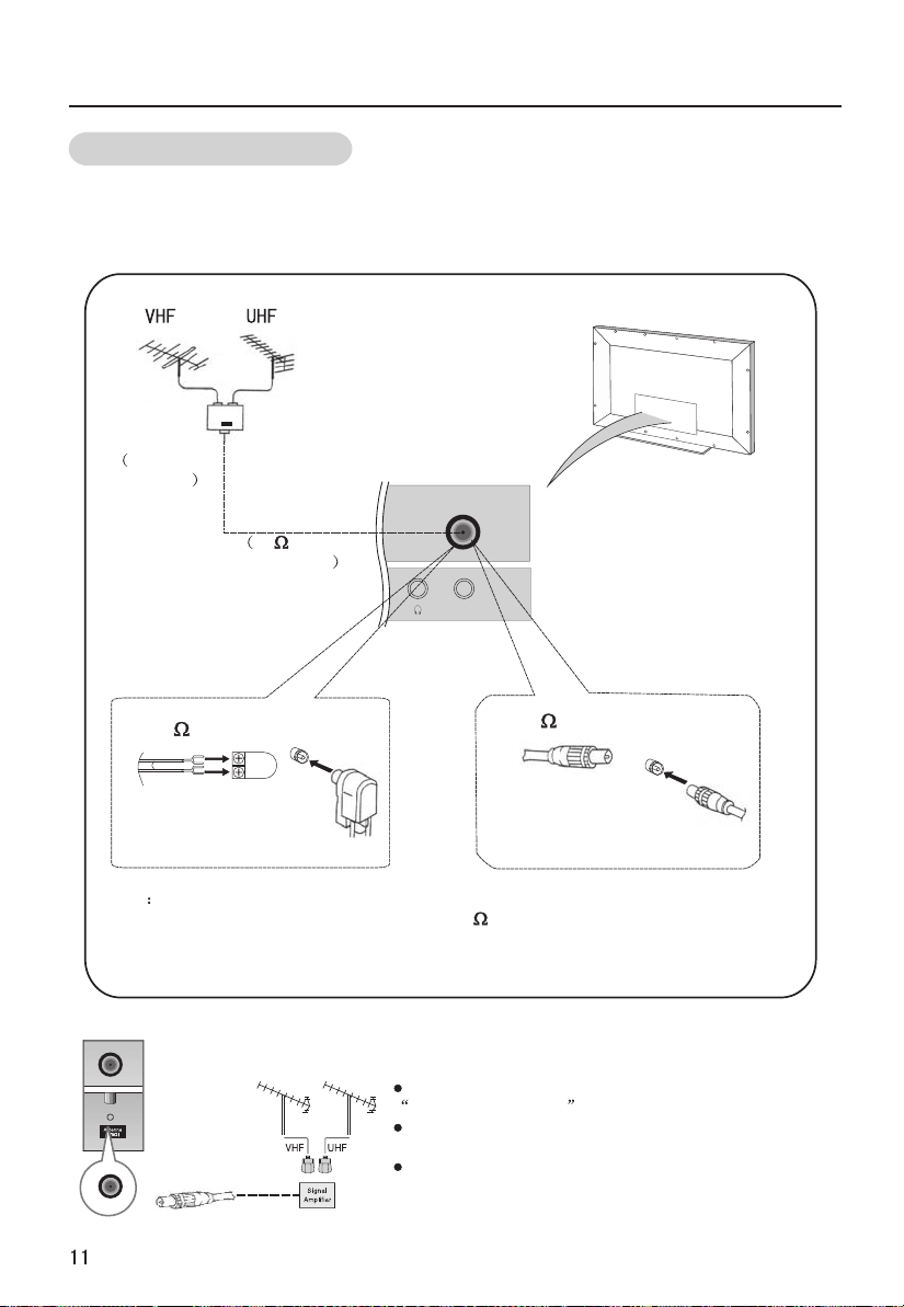
External Equipment Connections
Antenna Connection
Generally speaking, to enjoy a clearer picture, we recommend that you use a
CATV system or an outdoor antenna .In different places, the suitable antenna
type and position are different.
Mixer
additional
purchase
300 twin-lead cable
Antenna adapter
Note
* It is recommended that you'd better use 75
disturbance caused by airwave.
* Don't bind antenna cable and electric wire together.
outdoor
antenna
Antenna input
75 standard
coaxial type
ANT IN
75 coaxial cable
Plug
(additional purchase)
coaxial cable to remove the
If the antenna needs to be split for two Tv`s, install a
2-WaySignal Splitter in the connections.
If the antenna is not installed properly, contact your
dealer for assistance.
To improve picture quality in a poor signal area,
purchase and install a signal amplifier.
External Equipment Connection
NOTE: All cables shown are not included with the TV.
Choose Your Connection
There are several ways to connect your television, depending on the components you
want to connect and the quality of the signal you want to achieve. The following are
examples of some ways to connect your TV.
Choose the connection which is best for you.
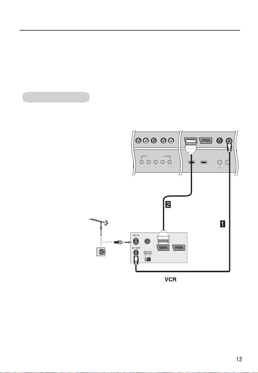
VCR connection
- To avoid picture noise (interference), leave an adequate distance between the VCR
And TV.
1. Connect the SCART cables from
the VCR's output jacks to the TV`s
input jacks, as shown in the figure.
COMPONENT IN
2. Insert a video tape into the VCR and
press PLAY on the VCR. (Refer to the VCR
owner`s manual.)
3. Select the input source
by the TV/AV button
on the remote control.
Pr/Cr Pb/Cb Y L-AUDIO-R
S-VIDEO
SCART2 SCART1
ANT IN
External Equipment Connections
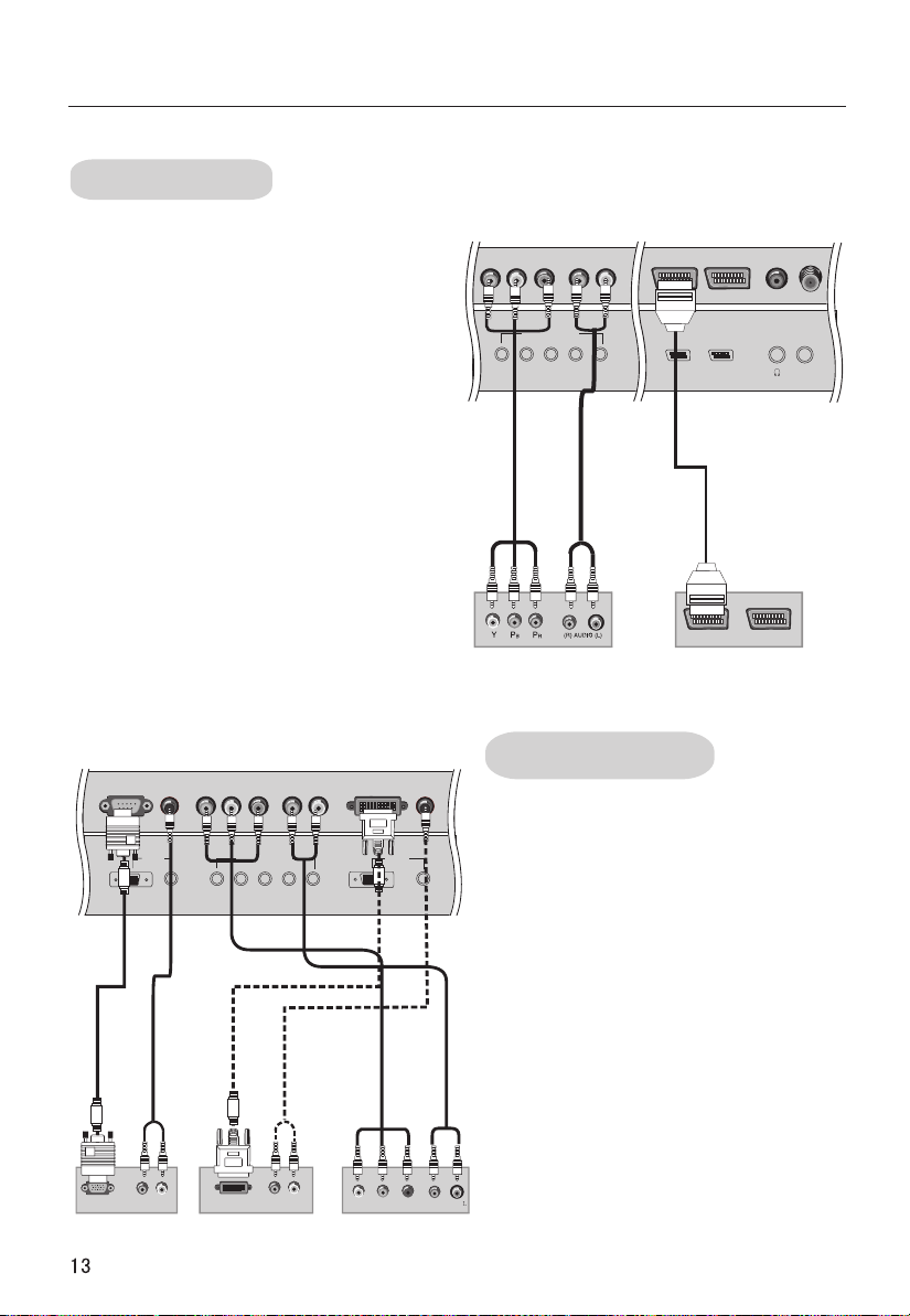
DVD connection
How to connect
1. Connect the DVD video outputs (Y,
Pb/Cb, Pr/Cr) to the COMPONENT IN jacks
on the TV and connect the DVD audio
outputs to the AUDIO IN jacks on the TV, as
shown in the figure.
2. If your DVD only has an SCART output
jack, connect this to the SCART input on
the TV. as shown in the figure.
NOTE: If your DVD player does not have
component video output, use S-Video.
How to use
1. Turn on the DVD player, insert a DVD.
2. Use the TV/AV button on the remote
control to select SCART mode.
3. Press Play button on external equipment
for program play.
4. Refer to the DVD player's manual for
operating instructions.
COMPONENT IN
Pr/Cr Pb/Cb Y L-AUDIO-R
SCART2 SCART1
or
DVD
ANT IN
VGA IN COMPONENT IN
VGA
RGB-DTV OUTPUT R AUDEO L
AUDIO
Pr/Cr Pb/Cb Y L-AUDIO-R
or
DVI-DTV OUTPUT R AUDEO L
Digital Set-top Box
DTV connection
-To watch digitally broadcast programs,
purchase and connect a digital set-top
DVI IN
DVI
AUDIO
or
YPbPr
box.
How to connect
Use the TV`s COMPONENT IN, VGA or DVI
port for video connections, depending
on your set-top box connections
available. Then, make the
corresponding audio connections.
How to use
1. Turn on the digital set-top box. (Refer
to the owner`s manual for the digital
set-top box.)
2. Use TV/AV on the remote control to
select DVI mode.
3.Press Play button on external
equipment for program play.
R AUDEO
External Equipment Connections
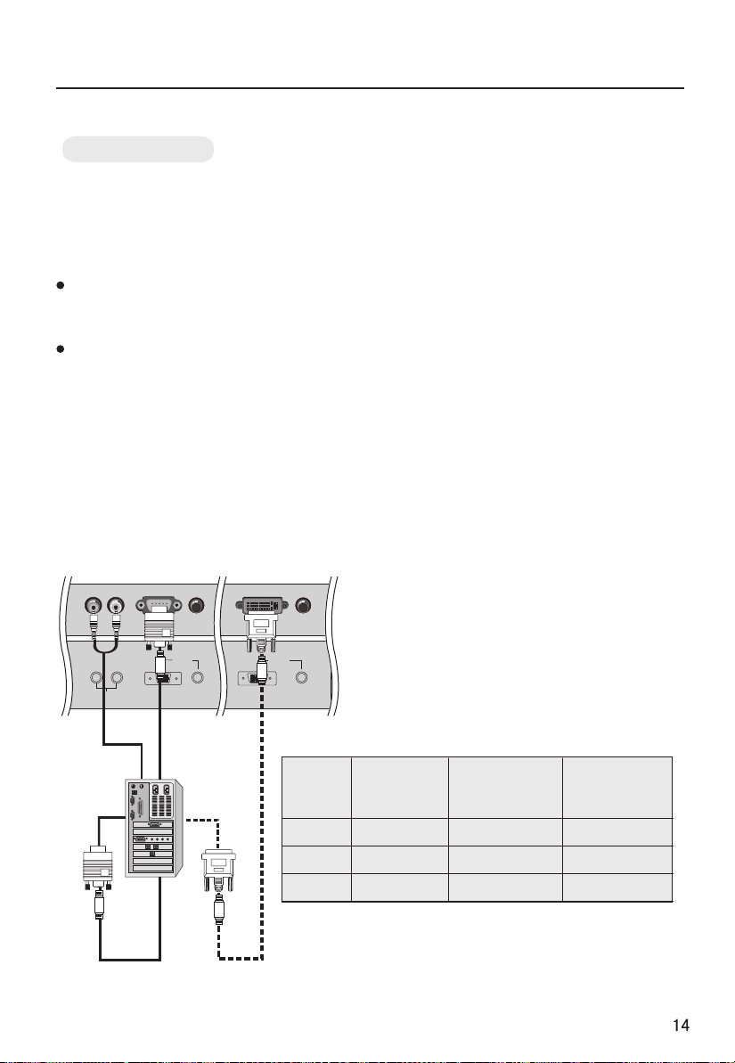
PC connection
How to connect
1. To get the best picture quality, adjust the PC
graphics card to (>1024
2. Use the TV`s VGA or DVI (Digital Visual
Interface) IN port for video connections,
depending on your PC connector.
If the graphic card on the PC does not output
analog and digital RGB simultaneously, connect
only one of eitherVGA r DVI IN to display the
PC on the TV.
If the graphic card on the PC does output
analog and digital RGB simultaneously, set the
TV to eithe DVI; (the other mode is set to
Plug and Play automatically by the TV.)
x768),60Hz.
IN
IN o
r VGA or
3. Then, make the corresponding audio
connection. If using a sound card, adjust the PC
sound as required.
How to use
1. Turn on the PC and the TV.
2. Turn on the display by pressing the POWER
button on the TV's remote control.
3. Use TV/AV on the remote control to select
VGA
DVI IN
DVI
AUDIO
L R
AUDIO OUT
VGA IN
VGA
AUDIO
or DVI source.
4. Check the image on your TV. There may
be noise associated with the resolution,
vertical pattern, contrast or brightness in
PC mode. If noise is present, change the
PC mode to another resolution, change
the refresh rate to another rate or adjust
the brightness and contrast on the menu
until the picture is clear. If the refresh rate
of the PC graphic card can not be changed,
change the PC graphic card or consult the
manufacturer of the PC graphic card.
NOTES:
1 Use a DVI cable.
2 Avoid keeping a fixed image on the TV's
screen for a long period of time. The fixed
image may become permanently
imprinted on the screen.
3 The synchronization input form for
Horizontal and Vertical frequencies is
separate.
Resolution
Mode
Resolution
frequency
(Khz)
Line
VGA
SVGA
XGA
640*480 31.5KHz 60Hz
800*600 37.9KHz 60Hz
1024*768 48.4KHz 60Hz
Note: All above listed are subject to VESA Criteria.
Frame
frequency
(Hz)
 Loading...