

Page 1

HAIER
COLOR TELEVISION
SERVICE MANUAL
PART # TV-8888-34
HAIER AMERICA TRADING, LLC
www.haieramerica.com
1
Page 2
Service Manual
Haier
Service Manual
For P42S6A-C1 / P42S6A-C2
●●●●
●●●● Built in tuner
Features
●●●●
Digital interface(DVI 1.0)
●●●● Auto Pixel shift for reduce image sticking
●●●● Graphic and video double window
●●●●
8W-2CH speaker out ,subwoofer out
●●●●
PC/DVI input resolution up to 1280*1024
●●●● HDTV signal interface
●●●● Power management function
Haier group
Edition:2003.11.11
1/57
Page 3

Service Manual
Haier
Content
Contents………………………………………………………………………….2
2.Features
3.Safety measures and Attention
4.Block Diagram
……………………………………………………………………….3
………………………………………….4
………………………………………………………………..5
5.IC description ……………………………………………………………….…7
6.IC layout &power map………………………………………………………10
6.1 IC layout & power map(digital board)
6.2 IC layout & power map(analog board)
7.Panel interface
…………………………………………………………….12
…………………………..10
………………………….11
7.1 Output signal timing_60HZ…………………………………………12
7.2 Output signal timing_50HZ…………………………………..12
7.3 Output signal timing diagram………………………………..13
7.4 LVDS bit mapping……………………………………………..14
7.5 Panel connect pin configuration……………………………..14
8.Power interface……………………………………………….……..15
9.Inspections on major Ics……………………………………………
16
10.Bom list……………………………………………………………..22
11.repair record………………………………………………………..53
11.1Record sheet:for reference……………………………….…53
2/57
Page 4

Service Manual
2.Features
●
● Built in tuner
●●
●
●
Digital interface(DVI 1.0)
●●
●
●
Auto Pixel shift for reduce image sticking
●●
●●●●
Graphic and video double window
●
● 8W-2CH speaker out ,subwoofer out
●●
●
● PC/DVI input resolution up to 1280*1024
●●
●
●
HDTV signal interface
●●
●
●
Power management function
●●
Haier
● Motion adaptive 3D Y/C Separation for composite NTSC video
signal
●
●
4H adaptive comb filter for PAL composite video signal
●●
●
●
Multi-stand color decoder PAL/NTSC/SECAM
●●
●
● Multi-stand video sync processing
●●
●
● Multi-stand sound process with Turbo sound
●●
●
●
Video window on graphic background
●●
●
●
Graphic window on video background
●●
●●●●
Independent scale factors in vertical and horizontal
●
● Graphic signal full sync processing
●●
●
● Motion-weighted interpolation for video source
●●
●
●
Bad-edit detection/correction
●●
3/57
Page 5

Service Manual
3. Safety measures and Attention
Haier
4/57
Page 6
Service Manual Haier
VPC_S_RST_N_51
RM1_IRQ_53
POWER_N_54
IR_INT1_55
CPU_UCS_N_57
IR_INT0_56
CPU_LCS_N_58
V_SUB_EN_N_59
V_MAIN_EN_N_60
PIN_DET_N_62
PD_LVDS_N_65
KEY_EN_N_65
68
SDA_TMR_69
CPU_RST_N_71
V_OE_N_72
SCL_STB_73
PC_AUDIO_SEL_N_74
SDA_STB_75
SCL1_76
SDA1_77
CPU_D[0:15]_78~95
G_LED_N_96
R_LED_N_97
CPU_TXD1_98
CPU_RXD1_99
FLI_RST_N_100
SCL_TMR
SDA_TMR
SDA_STB
SCL_STB
SCL1
SDA1
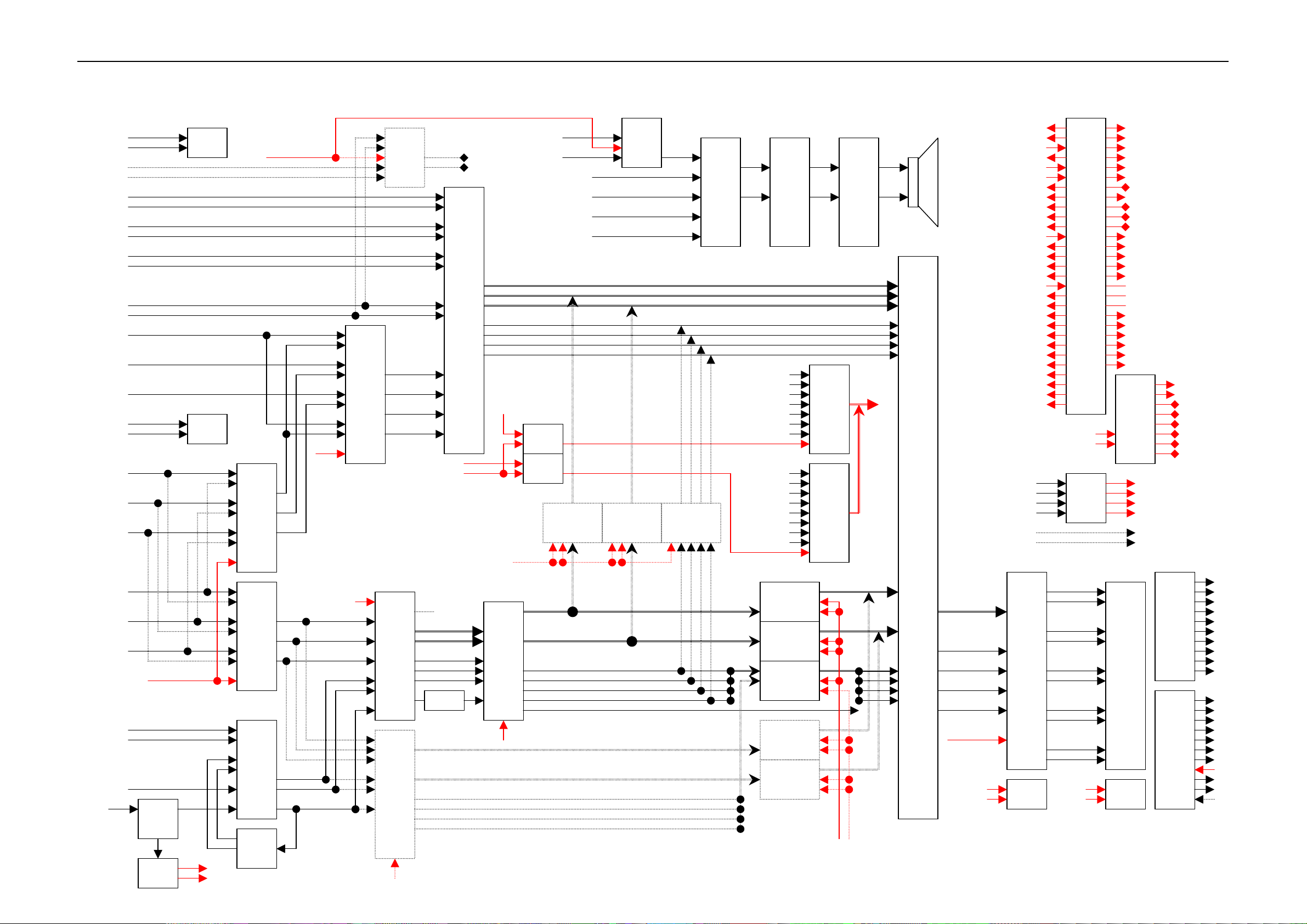
4. BLOCK DIAGRAM
DVI_SCL
DVI_SDA
DVI_V
DVI_H
DVI_RX2 +
DVI_RX2 -
DVI_RX1 +
DVI_RX1 -
DVI_RX0 +
DVI_RX0 -
PC_V
PC_H
PC_R
PC_G
PC_B
PC_SCL
PC_SDA
DTV_Y
DTV_Pb
DTV_Pr
DVD_Y
DVD_Pb
DVD_Pr
COMP1_DVD_SEL
S-Video_Y
S-Video_C
3D_Y
3D_C
Video_CVBS
AIR
AFT
Tuner
0xC2
PCF
8591T
Tuner_CVBS
3D_Y
3D_C
24C21
24C21
SCL1
SDA1
74HC
PC_AUDIO_SEL_N CPU_VSYNC
ADG774
DTV_Y
DTV_Pb
DTV_Pr
BA7657
(option)
BA7657
(option)
TEA6425
0x96
UPD
64083
0xB8
HDTV_SEL
VPC_M_RST_N
DVD_Y
DVD_Pb
DVD_Pr
C
Y
CVBS
CVBS
4052
R/Y_IN
G/Pb_IN
B/Pr_IN
R/G(SOG)_IN
VPC3230
MAIN
0x88
VPC3230
SUB
0x8E
(option)
CPU_HSYNC
KEY_EN_N
CPU_RD_N
VPC_Y[0:7]
VPC_C[0:7]
VPC_VS
VPC_HS
VPC_LLC1
VPC_FLD
74LCX74
DFF_FLD
SUB_Y[0:7]
SUB_C[0:7]
SUB_VS
SUB_HS
SUB_LLC2
SUB_FLD
VPC_S_RST_N
AD9887
0x98
PC/DVI_L/R
S-Video_L/R
DTV_L/R
DVD_L/R
Video_L/R
Tuner_SIF
D_IN[0:7]
D_IN[8:15]
D_IN[16:23]
D_ACTIVE
DIN_CLK
D_HSYNC
D_VSYNC
PIN_DET_N
V_OE_N
FLI2200
0xC0
FLI_RST_N
74HC02
74HC02
V_IN[0:7]
V_VS
V_HS
VCLK
V_ACTIVE
V_VALID
74HC
4052
74ACT244 74ACT244 74ACT244
5/57
MSPG
3450G
0x80
VIDEO_DET
SVHS_DET
DVD_DET
DTV_DET
PC_DET
DVI_DET
THER_DET
ENTER
SOURCE
MENU
VOL -
VOL +
CH -
CH +
POWER
74ACT244
74ACT244
74ACT244
74ACT244
74ACT244
V_MAIN_EN_N
TL062
CDT
74HC244
74HC244
TA2024
CPU_D[0:7]
V_SUB_EN_N
RM-1A
G_Port
V_Port
SCL_TMR_
OP_A[0:23]
OP_HSYNC
OP_VSYNC
OP_ENABLE
CLK_OUT
PD_LVDS_N
TX1
RX1
TX2
RX2
PHONE_TX
PHONE_RX
DS90C
385
PCF
8573T
CPU
MAX
232A
TxOUT0 -
TxOUT0 +
TxOUT1 -
TxOUT1 +
TxOUT2 -
TxOUT2 +
TxOUT3 -
TxOUT3 +
TxCLKOUT-
TxCLKOUT+
01_CPU_RXD0
02_CPU_TXD0
03_HDTV_SEL
04_CPU_BHE_N
05_CPU_WR_N
06_CPU_RD_N
07_ALE
08_ARDY(3.3V)
09_S2
10_S1
11_S0
13_X1
14_X2
16_RM1_CLK_IN
17_25MHz_AD9887
19~40_A[19:0]
42_WHB
43_WLB
44_HLDA
45_HOLD(GND)
46_HW_MONITOR
47_NMI(GND)
48_WRITE_PROTECT
49_RM1_RST_N
50_RM1_CS_N
PCF
8574T
CPU_TXD0
CPU_RXD0
CPU_RXD1
CPU_RXD1
FI_WE
31P_HF
24C16
Analog
PWR
Digital
PWR
P0_COMP1_DVD_SEL
P1_MUTE
P2
P3
P4
P5
P6
P7
10P
11P
A6V
GND
A12V
GND
12Vam
12Vam
GND
GND
A33V
GND
A5V
GND
D3.3V
D3.3V
GND
GND
NC
POWER_N
GND_STB
STB_5V
THER_DET
Page 7
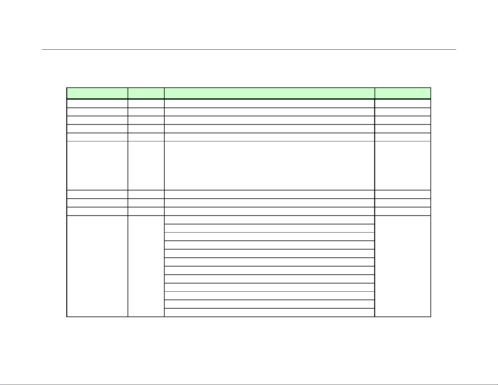
5. IC DESCRIPTION
ANALOG DEVICES
Name Package Description Manufacture
KIA78D05F DPAK Regulator
KIA78D09F DPAK Regulator
LP3961EMP-2.5 SOT 223-5 Regulator
LM1086ISX_3.3V TO-263 Regulator
LP3961EMP-1.8 SOT 223-5 Regulator
R8820LV PQFP 80
M29W160DB TSOP FLASH MEMORY
M24C16 SOP 8 EEPROM
74VHC08 SOP 8 2 input AND Gate
Service Manual
MICOM
1) Multiplexed address and data bus which is
compatible with 80c186 microprocessor
2) Supports nonmultiplexed address bus[A19 : A0]
3) 1M byte memory address space
4) 64K byte I/O Spaec
RGB Graphics Processing
Scan Converters
Aanlog Interface
1) 140 MSPS Maximum Conversion Rate
2) 330 MHz Analog Bandwidth
MQFPAD9887KST
3) Full sync processing
4) Midscale Clamping
5) 4:2:2 Output Format Mode
Digital Interface
1) 112MHz Operation(2pixels/clock mode)
2) High skew tolerance of 1 full input clock
3) Sync Detect for "hot plugging"
Haier
KEC
KEC
NATIONAL
NATIONAL
NATIONAL
RDC
ST
ST
FAIRCHILD
7/57
Page 8

Service Manual
MICRONAS
Haier
Name Package Description Manufacture
LVDS Transmitter
DS90C385 TSSOP
MAX821 SOT143 Power-on Reset
74AHC244 SOP Octal Buffer and Line Driver
74VHC02 SOP Quad 2-Line NOR Gate
74LCX74 TSSOP D-Type Flip-Flop
VPC3230D QFP
FLI2200 TQFP
+3.3V Programmable LVDS Transmitter 24-BIT Flat Panel
Display Link-85 MHz , +3.3V Programmable LVDS Transmitter
18-Bit Flat Display Link-85 Mhz
Comb Filter Video Processor
1) High-performance adaptive 4H comb filter Y/C separator
With adjustable vertical peaking
2) Multi-standard color decoder PAL/NT/SECAM
3) Line-locked clock, data and sync, or 656-output interface
4) peaking,contrast, brightness,color saturation and
tint for RGB/YCrCb and CVBS/S-VHS
5) PIP processing for picture sizes whit 8 bit resolution
6) 15 predefined PIP display configuration and expert mode
Digital component video deinterl
1) Motion-adaptive video deinterlacing selects optimal
filtering on a per-pixel basis
2) Supports 525/60(NTSC), 625/50(PAL/SECAM)
3) Accepts up to 1100 pixels/line
4) 8/10-bit , 16/20-bit YUV,24/30-bit RGB or YCbCr/YPbPr
Progressive output option
5) High-order filtering produces smooth chroma output in
4:2:2 to 4:4:4 or 4:4:4 to 4:2:2 conversion
NATIONAL
MAXIM
PHILIPS
FAIRCHILD
ST
FAROUDJA
8/57
Page 9

Service Manual
Haier
Name Package Description Manufacture
MAX232ACSE SOP RS232 Transceivers
TCPS9091PD27A tuner Tuner
24C21 SOIC EEPROM ST
74HC4052 SOP 4-Channel Analog DE/Multiplexer
BA7657F SOP Switch ic
74ACT244 TSSOP Octal Buffer and Line Driver
PCF8563T SOP CMOS Real-time Clock
K4S643232f TSOP DRAM
K6T4016V3C TSOP SRAM
TEA6425D SO20L Video Cellular Matrix
KIA78D09F DPAK Regulator
RM1A-A BGA-352 scaler
PCF8574T SOT162 Remote 8-bit I/O Expander
TA2024 PSOP30 Digital Audio Amplifier Driver
TL062CDT SO8 J-FET Dual Operational Amplifiers
MSP3450G PQFP80 Multistandard sound processor family
Three-dimensional Y/C separation lsi with on-chip memory
1) upd64083 realizes a high precision Y/C separation
2) noise reduction by three-dimension signal processing for NTSC signal
UPD64083GF QFP100
3) on-chip 4-Mbit memory for flame delay,2ch of high precision intermal
10-bit A/D converter, and adapting 10-bit signal processing and high
picture quality
4) upd64083 is completely single-chip system of 3D Y/C separation
5) This LSI includes the wide
MAXIM
SEC
PHILIPS
ROHM
FAIRCHILD
PHILIPS
Samsung Elec.
Samsung Elec.
ST
KEC
OPLUS
PHILIPS
TRIPATH
ST
MICRONAS
NEC
9/57
Page 10

Service Manual
12
12
12
12
14
S-
RS232I
Haier
6. IC layout &power map
74VHC
02
74AHC
P
244
C
O
N.
MAX
821
STB5V
MAX
2323E
RS232 OUT
74VHC
STB3.3V
02
74AHC
K6T4016V3C
R8820LV
24C16
M29W160DB
PCF
8563T
244
STB3.3V
STB5V
N
K4S
643232F
STB3.3V
STB5V
A5V
LM
2937
3,3
6.1 IC layout & power map(digital board)
31P CON.
D3.3V
K4S
643232F
RAMBRANT-1A
STB5V
A5V
AD9887KS
-140
A3.3V
4FC
216
STB5V
A5V
DVI
24C16
K4S
643232F
D1.8V
D3.3V
D3.3V
74ACT
244
A3.3V
LM
2937
3,3
Audio_PC/DVI_LR
LP
9361
1.8
D3.3V
ADG774
DS90C385
D2.5V
74ACT
244
74ACT
244
74VHC
08
STB5V
STB3.3V
74ACT
244
A5V
PC
4FC
216
IS-3.3
D3.3V
D2.5V
D3.3V
74HC
D2.5V
LM
1086
74ACT
244
74ACT
244
FLI2200
K4S643232F
4052
Audio_SVideo_LR
11P CON.
A6V
STB5V
LP
9361
2.5
STB5V
D3.3V
78D
LM
Z86129
2937
05F
3,3
D3.3V
74ACT
244
A5V
A5V
VPC
74ACT
244
74LCX7
4
3230
IS-3.3
D3.3V
LM
1086
VPC
3230
74HC
4052
A5V
Video
Audio_Video_LR
P
C
O
N.
P
C
O
N.
P
C
O
N.
P
C
O
N.
10/57
Page 11

Service Manual
12
12
12
12
6.2 IC layout & power map(analog board)
Haier
P
C
O
N.
P
C
O
N.
P
C
O
N.
P
C
O
N.
A33V
LM
2940
IMP8
10P CON.
12Vamp
A12V
A8V
A6V
TEA
6425D
78D
05F
A5V
BA7657F
UPD
64083
78D
09F
A9V
A2.5V
BA7657F
LP
2961
2.5V
A3.3V
PCF
8574T
A5V
A2.5V
LM
2937
3.3V
LP
2961
2.5V
PCF
8591T
A5V
LM
2940
IMP8
12Vamp
12Vamp
MSP
3450G
TL062
CDT
A9V
A5V
A33V
TCPS9091PD27A
TA2024
A5V
A5V
VIDEO
DTV
Audio_DTV_LR
DVD
Audio_DVD_LR
Audio_OUT_LR
RF
Woofer
11/57
Page 12

7.Panel interface
Service Manual
Haier
7.1 Output signal timing_60HZ
SIGNAL TIMING SIGNAL TIMING
Dot Clock 27 M HZ
H-Frequency 31.05HZ V-Frequency 59.99 HZ
H-Total 896 dots V-Total 533 H
H-Front Porch 16 dots V-Front Porch 12 H
H-Sync 12 dots V-Sync 2 H
H-Back Porch 16 dots V-Back Porch 29 H
H-Active 852 dots V-Active 480 H
H-Sync Polarity P V-Sync Polarity P
7.2 Output signal timing_50HZ
SIGNAL TIMING SIGNAL TIMING
Dot Clock 27 M HZ
H-Frequency 31.05HZ V-Frequency 50 HZ
H-Total 896 dots V-Total 639 H
H-Front Porch 10 dots V-Front Porch 12 H
H-Sync 24 dots V-Sync 2 H
H-Back Porch 10 dots V-Back Porch 135 H
H-Active 852 dots V-Active 480 H
H-Sync Polarity P V-Sync Polarity P
12/57
Page 13

Service Manual
7.3 Output signal timing diagram
HORIZONTAL TIMING DIAGRAM
12 D 16D 852D 16D
896D
VERTICAL TIMING DIAGRAM
2 H 12H 480H 29H(135H)
533H(639H)
Haier
13/57
Page 14

Service Manual
Haier
7.4 LVDS bit mapping
Pin Name signal Pin Name signal Pin Name signal Pin Name signal
TXIN0 R0 TXIN7 G0 TXIN14 G5 TXIN21 B4
TXIN1 R1 TXIN8 G1 TXIN15 B0 TXIN22 B5
TXIN2 R2 TXIN9 G2 TXIN16 B6 TXIN23 FIELD
TXIN3 R3 TXIN10 G6 TXIN17 B7 TXIN24 HSYNC
TXIN4 R4 TXIN11 G7 TXIN18 B1 TXIN25 VSYNC
TXIN5 R7 TXIN12 G3 TXIN19 B2 TXIN26 ENABLE
TXIN6 R5 TXIN13 G4 TXIN20 B3 TXIN27 R6
7.5 Panel connect pin configuration
PIN NO. signal PIN NO. signal PIN NO. signal PIN NO. signal
1 GND 9 GND 17 GND 25 N.C.
2 GND 10 GND 18 GND 26 GND
3 Txout0- 11 Txout2- 19 Txout3- 27 N.C.
4 Txout0+ 12 Txout2+ 20 Txout3+ 28 GND
5 Gnd 13 GND 21 GND 29 N.C.
6 Gnd 14 GND 22 GND 30 GND
7 Txout1- 15 TxCLKout0- 23 GND 31 N.C.
8 Txout1+ 16 TxCLKout0+ 24 GND
14/57
Page 15

8.Power interface
Service Manual
Haier
PIN
NUMBER
1 A5V A6V
2 GND GND
3 D3.3V A12V
4 D3.3V GND
5 GND 12VAMP
6 GND 12VAMP
7 NC GND
8 POWER-N GND
9 GND A33V
10 STB5V GND
DIGITAL BOARD
INPUT POWER(CN6001)
ANALOG BOARD
INPUT POWER(CN1000)
11 THER_DET
15/57
Page 16

Service Manual
Haier
9.Inspections on major ICs
9.1R8820LV(DIGITAL:U9102)-MICOM
(1)Check whether the proper power is supplied(3.3v)
(2)Check whether the No.71 Reset pin’s output is high.
(3)Check I2C-BUS (I2C :PINS 76 and 77)
(4)Check whether the inputs/outputs betwenR8820LV and MEMORY(U9101,U9103) are normal.
(5)Check whethet the 25MHZ clock is connected to pins 13 and 14.
9.2VPC3230(digital:U9513)_Check when the input mode is set for TV,VIDEO,S-VIDEO,DVD
(1) Check whether the proper power is supplied.(5v,3.3v)
(2) Check whether the No.15 Reset pin’s output is high.
(3) Check the I2C-bus(pin 13 and 14).
(4) Check whethet the output clock of llc1(pin 28) is 13.5M HZ.
(5) Check the output on VPC_h sync(pin56),VPC_VYNC(PIN57),VPC_FIELD(PIN53).
(6) Check whethet the 20.25Mhz clock is connected to pins 62 and 63.
16/57
Page 17

Service Manual
Haier
(7) Check the digital data outputs.
9.3 TEA6425D(ANALOG:U1002)
-VIDEO Switching IC_Check when the input mode is set for TV,VIDEO,S-VIDEO
(1) Check whether the proper power is supplied.(8v)
(2) Check the I2C bus (pin2 and pin4).
(3) Check whether the inputs/outputs are normal.
9.4 MDIN-150(digital :U9507)
-DEINTERLACE_Check when the input mode is for TV,VIDEO ,S-VIDEO,DVD.
(1) Check whether the proper power is supplied(3.3v,2.5v)
(2) Check whether the NO.209 Reset pin’s output is high.
(3) Check the I2C-bus (pins 62 and 64).
(4) Check whether the 27Mhz clock is connected to pins 186 and 187.
(5) Check whether the data inputs are normal.
VPC-CLK(pin 195):13.5MHZ,VPC_HSYNC(pin 189):15.75Khz,
17/57
Page 18

Service Manual
Haier
VPC_VSYNC(pin 188):60HZ,VPC_FIELD(pin 194)
(6) Check whether the data outputs are normal.
V_CLK(pin159):27MHZ,V_HYNC(pin 165):31.5Khz,V_VSYNC(pin 168):60HZ,V_ACTIVE (pin
164),D_V_VALID(pin163)
(7) Check whether the inputs and outputs between MDIN-150 and MEMORY (U9501) are normal.
9.5 TCP9091PD27A(ANALOG:U1001)_Check when the input mode is set for TV
(1) Check whether the proper power is supplied .(33V,5V)
(2) Check the I2C bus (pin 2 and 4).
(3) Check whether the inputs/outputs are normal.
9.6 AD9887AKS(digital:U9201)-A/D CONVERTER_Check when the input mode is DTV,PC,DVI.
(1) Check whether the proper power is supplied(3.3V)
(2) Check I2C bus (pins 91 and 92).
(3) Check whether the inputs/outputs are normal.
INPUT:
18/57
Page 19

Service Manual
Haier
PC INPUT:pin119®,110(G),100(B),81(VSYNC),82(HSYNC)
DTV INPUT:pin119(Pr),110Y,100(Pb),
DVI INPUT:pin 59(Rx1+),60(Rx1-),62(Rx0+),63(Rx0-),65(RXC+),66(RXC-),56(RX2+),57(RX2-)
OUTPUT:
Pin 134(DIN_CLK),135(DIN_ACTIVE),139(D_HSYNC),138(D_VYSNC)
9.7 ADG774BR(DIGITAL:U9202)-Switching IC_Check when the input mode is for TV and PC.
(1) Check whether the proper power is supplied (5v).
(2) Check the SEL_PIN(PIN1:DVI HIGH;PC:LOW)
(3) Check whether the inputs/outputs are normal.
9.8REMBRANDT-1A(DIGITAL:U9001)-SCALER IC-Check the all input image and SOD
(1) Check whether the proper power is supplied.(5v,3.3v,1.8v)
Because it is BGA IC ,measure the R or C parts on the power terminals.
(2) Check whether the inputs and outputs between R8820LV and MEMORY (U9006,U9007,U9008) are
normal.
19/57
Page 20

Service Manual
(3) Check whether the outputs of MDIN-150 and AD9887AKS are input into REMBRANDT-1A are normal.
(4) Check whether the data inputs/outputs are normal.
PinAD8(RM1_IRQ),AE9(OCLK_OUT),AF8(RST_N),AF5(OP_EN),OD5(OP_HSYNC),
PinAC5(OP_VSYNC),AE6(OP_FIELD),AD6(OPLL_CLK_IN),AC7(OP_FIELD_3D)
9.9DS90C385(DIGITAL:IC603)-LVDS TRANSMITTER
(1) Check whether the proper power is supplied (3.3v).
(2) Check whether the power down pin’s (pin 32)output is high.
(3) Check whether the outputs of REMBRANDT-1A are input into DSC90385 normally.
(4) Check whether the LVDS data outputs are normal.
Haier
9.10UPD64083GF_3BA(ANALOG:U9700)-3D COMB FILTER
-Check when the input mode is for TV (NTSC) and Video(NTSC)
(1) Check whether the proper power is supplied (3.3V,2.5V).
(2) Check I2C bus (pin 59 and 60).
(3) Check whether the 20 M HZ CLOCK is connected to pins 47 and 48,
20/57
Page 21

Service Manual
(4) Check whether the data inputs are normal.
Input::AY1(pin 88)
Output::ACO(pin83),AYO(pin 84)
9.11SP3450G(ANALOG:U6002)-Multi stand sound processor
(1) Check whether the proper power is supplied (5v,8v).
(2) Check I2C bus (pin 2 and 3).
(3) Check whether the 18.432 M HZ clock is connected to pins 71 and 72.
(4) Check whether the inputs/outputs are normal
INPUT:SIF(pin 67),SC1_IN_R(pin 57),SC1_IN_L(pin 56),SC2_IN_R(pin 54),SC2_IN_L(pin
Haier
53),SC3_IN_R(pin51),SC3_IN_L(pin50),SC4_IN_R(pin48),SC4_IN_L(pin 47),
OUTPUT:audio out L,R(pin 33,34),DACM L,R(PIN 27,28),DACM SUB(pin 30)
9.12 TA2024(ANALOG:U6000)-Digital Audio Ampifier Driver
(1) Check whether the proper power is supplied (12V).
(2) Check whether the inputs/outputs are normal.
21/57
Page 22

Service Manual
Web side:http://www.haier.com
Haier
Haier
Group
Tel:86-532-8938356
54/57
Page 23

Service Manual
Haier
55/57
 Loading...