

Page 1
Semi-electronic
Microwave Oven
Service Manual
MK-2280M
MK-2280MG
Features
●
Safe to use
●
Shining appearance
●
● Healthy and germicidal
High-temperature grill (Only MK-2280MG)
●
Haier Group
Edition:2005-11
- 1 -
- 11
Page 2

Contents
Contents
1. Contents……………..…………………………………………………………………1
2. Product Code illumination and Series Introduction ……………………...…...2
3. Features….……………………………………………………..…………………….3
4. Specifications……..…………………………………………...………………….4
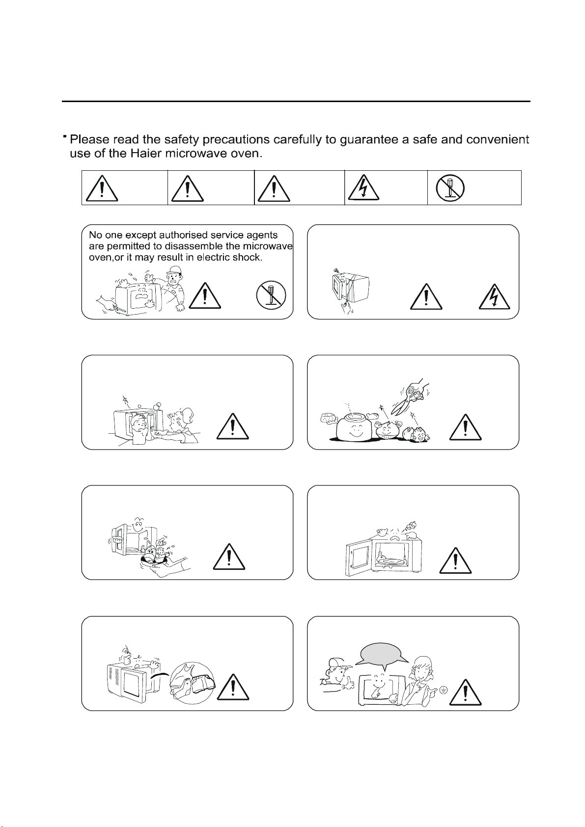
5. Safety Precaution…………………………………………..………………………5
6. Warning and Cautions……………………………………………………………..6
7. Installation and Accessory Parts…………………………………………………9
8. Parts and Functions………………………………………………………………..11
9. Maintenance Service and Trouble Shooting…………………………………...12
10. Circuit Diagram and Circuit Explanation………………………………………..23
11. Exploded View and Part of Lists
………………………………………………...29
- 2 -
Page 3

Product Code illumination and Series Introduction
2.Product Code illumination and Series Introduction
Model Identification
M K -□ □ □ □ □ □
A B C D E F
A: Abbreviation of Microwave Oven.
B:Appearance
c: Code name of Nominal cavity capacity.
D: One tenth of the microwave output power consumption.
E:Type of operation
M:Mechanical E:Electronic
F---Function With G:Grill function
Examples:
MK-2280MG:
It represents mechanical microwave oven with grill function, the cavity
volume is 21L, the microwave output power is 800w, K appearance.
MK-2280M:
It represents mechanical microwave oven without grill function, the cavity
volume is 22L, the microwave output power is 800w, K appearance.
- 3 -
Page 4

Features
3.Features
3.1 Safe to use
The door adopts unique anti-choke structure and integrated punch forming, and thus
effectively prevents the microwave from leaking.
It is controlled by two-step interlock switch. The power will be switched off
automatically when the door is open, therefore it is much safer to use.
3.2 Shining appearance
The door shell and operation panel frame shell adopt in ported high-quality stainless
steel material, and will never get rust and change color. It has modern appearance and
superior quality, and thus becomes the best choice for the household microwave oven.
3.3 Healthy and germicidal
It is produced with antiseptic materials, and can suppress the reproduction of the
bacteria effectively. The special function of the microwave oven can eliminate the germ in
the food quickly and completely.
3.4 Simple operation and accurate time counting
With two knobs, one for adjusting time and another for power levels, plus LED display,
on which cooking time is displayed, it has feature of simple operation of mechanical
microwave oven as well as accurate time counting of electronic microwave oven.
- 4 -
Page 5
4.Specifications
Item Description
Model MK-2280M MK-2280MG
Specifications
Power source
~230V/50Hz ~230V/50Hz
Input Power consumption 1300W 1300W
output Power consumption 800W 800W
Power consumption
-------- 1000W
For grill
Oscillating frequency 2450MHz
Timing range 30’
Power level 4 4
Unit Dimension
(W×D×H)mm
486×370×288 486×370×288
Cavity Dimension
(W×D×H)mm
302×318×221 302×318×221
Carton Dimension
(W×D×H)mm
538×394×350 538×394×350
Volume/
22L 21L
effective volume
Weight(unit/carton) 14Kg 14.5Kg
Instruction manual, glass tray, turn
Accessories
plate-bracket groupwaregl, turn axis
- 5 -
Page 6
Safety Precaution
5.Safety Precaution
Only professional technicians can do the maintenance. Please refer to the proper
maintenance procedures in the service manual for safe operations, so as to avoid
unexpected injury.
Points of attention during maintenance:
1. Do not operate the microwave oven while the door of the oven is open.
2. Please check following before operation: (1) the door lock is flexible; (2) the door
works well in opening and closing; (3) the door is sealed well (without deforming and
bending); (4) identify any damage and loosening of the components and accessories;
(5) identify damages owing to abnormal usage or dropping.
3. Please confirm that the magnetron, microwave conductor pipe and wire are installed
and connected well before switch on the power to do maintenance or check the
functional components.
4. In case that the door lock, seal gasket, microwave radiating and transmission system
are damaged, or something wrong in debugging, please make repair, replacement or
adjustment according to the requirement of this manual before usage.
Components detachable that may
touch voltage higher than 250V
1. Magnetron
2. High-voltage transformer
3. High-voltage capacitor
4. High-voltage diode
5.
H.V. FUSE
During maintenance, the technicians shall pay attention that:
Microwave radiation
Do not expose to the radiation emitted by the microwave generator or other parts
transmitting the microwave.
Components that may cause excessive
microwave leakage
1. The magnetron is not properly installed on the
wave guide;
2. The door hook, door body and the up/down
hinge are not properly adjusted;
3. The door body or the shell is damaged;
The above reasons may cause excessive
microwave leakage.
Attention
- 6 -
Page 7
Safety Precaution
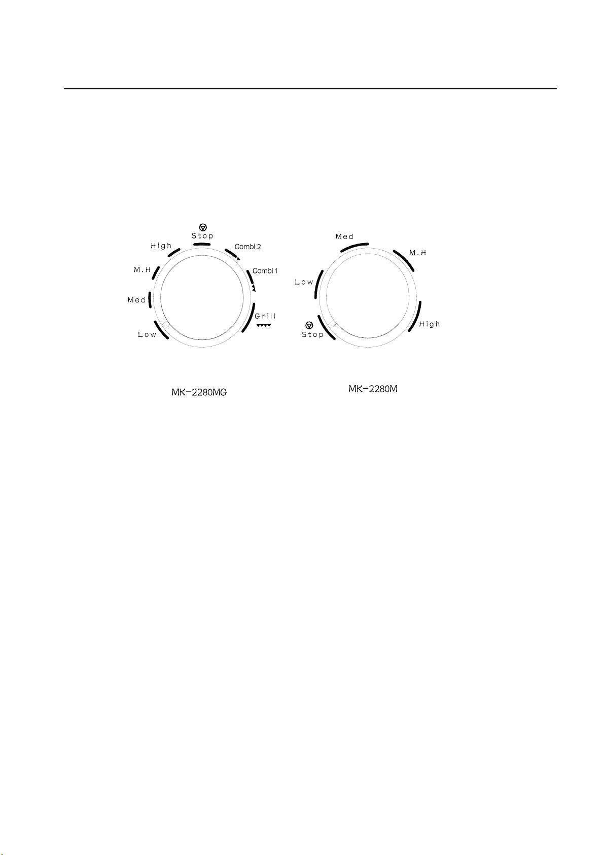
Attention: The mark must be exactly lined up with a power level. Otherwise there is a continuous
beep tone indicating microwave can’t work properly.
- 7 -
Page 8
6.Warning and Cautions
Warning and Cautions
Danger
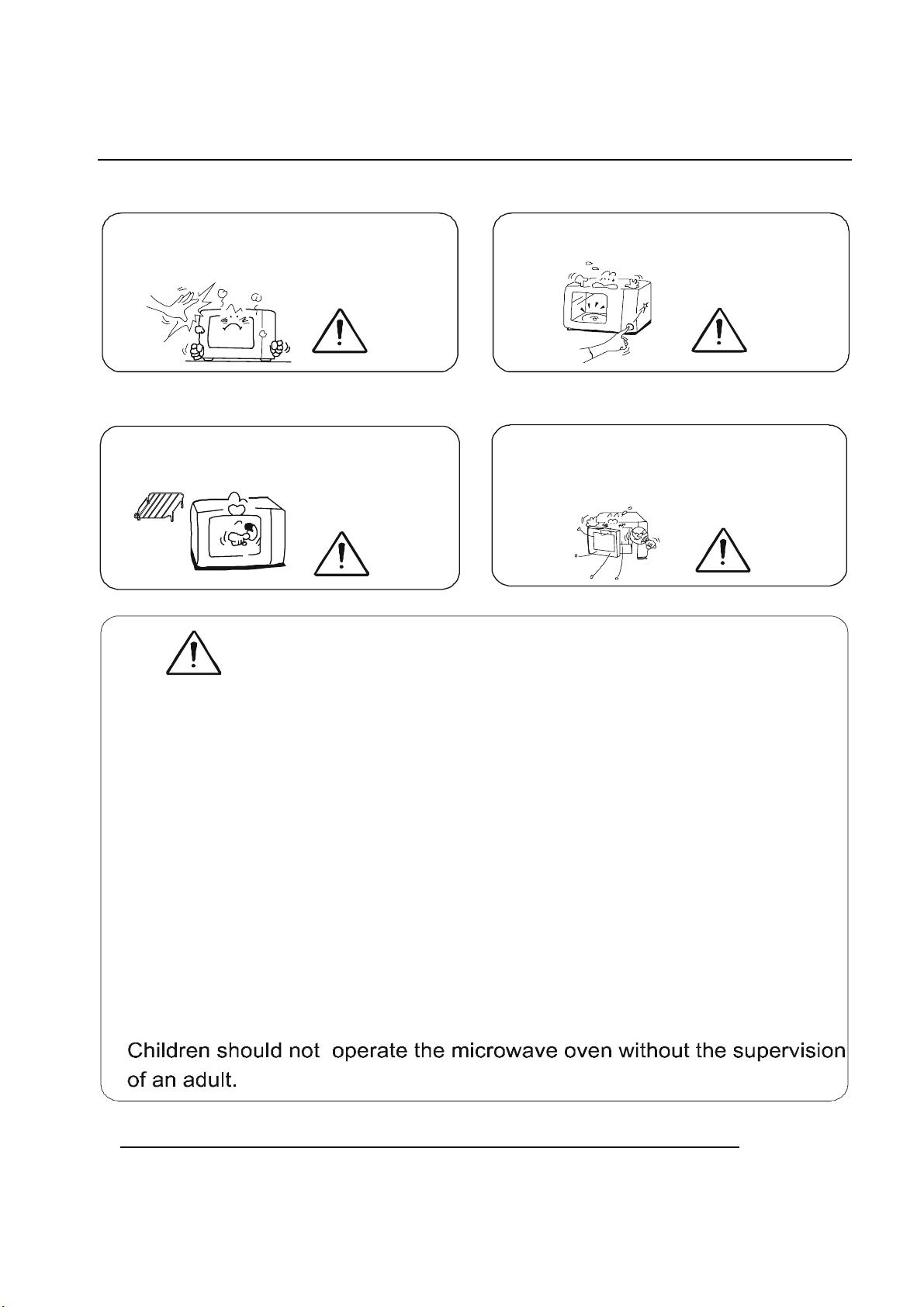
Do not apply excessive force to the door.
It may cause distortion of the door and
result in microwave leakage.
Warning
Danger
warning
Electric
Attention
shock
hazard
Do not use a metal rod to enter the interlock
switch hole on the front side of the cavity.
interlock switch hole
Danger
Do not use sealed containers. For those
foods with skin, please prick holes on the
skin.
No
dismantle
warning
Do not cook eggs in their shell as they may
burst.
warning
Do not use the microwave oven for purposes
other than for cooking food.
warning
- 8 -
Remember to clear away excess grease
form the inside the cavity. Otherwise it may
cause smoke or fire during heating.
warning
This appliance must be earthed.
safe and
reliable
warning
Page 9
A
Warning and Cautions
When roasting, the face of the door and
the top of the cabinet may become hot to
touch.
warning
Do not use metallic dishware to cook as it
will cause internal arcing.
warning
Waring
Do not use the microwave with the cavity
empty. It will damage the microwave oven.
warning
llow the cavity to cool after long cooking
processes (i.e. Roasting) before starting
another cook cycle.
warning
If the door seal or the door body is damaged, please do not use the
1.
appliance until it is repaired by an authorised service agent.
2. Before use, please check if the cooking containers are suitable for
the microwave oven.
3. If you find smoke in the oven, leave the door in the closed position, and
switch off the power supply of the microwave (remove the plugtop from
the supply socket).
4. We do not recommend the use of plastic, paper or other combustible
containers for cooking, Please be sure to observe the operating
instruction for the microwave oven, in order to avoid accidents.
5. When you heat liquid in the oven, please take care of delayed bubbling
because of boiling liquid.
Do not use the microwave oven if there is no food inside.
6.
7.
Do not use product for any industrial and commercial purpose.
- 9 -
Page 10

Warning and Caution
1 Baby food or drink should be shaken or stired evenly so that the heat is distributed and
may only be handed to your child after having checked the temperature of the food or
drink.
2 .Never put combustible materials near the microwave oven. Watch the cooking
condition while the microwave oven is working. Set cooking time correctly, for over time
setting may cause fire.
POINTS OF ATTENTION
Not like the other household appliances, the microwave oven is a kind of
high-voltage appliance. Although common operations will not risk the user in
hazard, please operate it carefully.
1. Do not use duplex receptacle in usage and maintenance.
2. Do not touch any components and circuit when the microwave is running.
3. Be sure to switch off the power before you touch the inside structure of the oven.
4. The high-voltage capacitor may still maintain electricity even 30 seconds after the
microwave oven stops working. To make replacement or checking at this time, be sure
to use insulated screwdriver to short out the two ends of the capacitor and discharge
the stored electricity.
5. Prevent the wristwatch from touching the microwave oven.
6. Do not operate the microwave oven when there is no food or water inside.
7. Protect the seal gasket and front board of the oven door from damage.
8. Do not put metal tools on the magnetron.
9. Do not put any items into the hole of the door lock or the door lock switch.
10. Confirm that the magnetron is installed properly and firmly.
Only professional technicians can do the maintenance of this
microwave oven.
- 10 -
Page 11
7.Installation and Accessory Parts
7.1 Installation
Installation and Accessory Parts
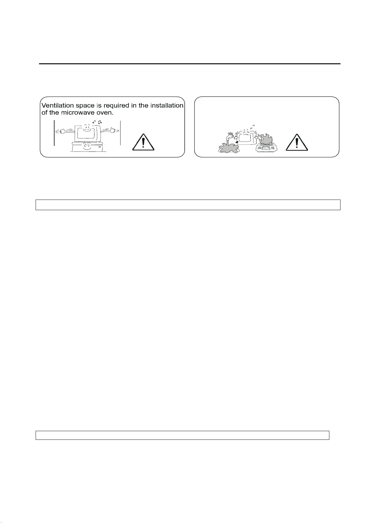
Do notinstall the microwave oven in
an environment that is humid or with
high temperature.
attention
7.2 key Point In Installation Adjustment
Attention
Please read following before installation.
7.2.1 Install the microwave oven
1. Clear all of the items inside the oven, then wipe the cavity with wet soft cloth. Check if
the door is even, and if there’s damage on the inner/outer side of the door.
2. The microwave oven, the food and the cooking tools shall be placed on firm and stable
table, desk or shelf. During delivery please note that the side with control panel is much
heavier.
3. Do not block the ventilation hole and air inlet. Otherwise it may damage the oven or
cause poor cooking. Confirm that the oven shelf is placed properly to guarantee the
ventilation.
4. Avoid high temperature and vapor. Protect the appliance and the mechanical part from
damages.
5. The ambient temperature shall be lower than 40℃.
6. The plane bearing the oven shall be even and firm.
7. Keep the microwave oven away from the TV, radio, computer, etc. to avoid
interference.
7.2.2 Installation of the earth wire
The microwave oven must be earthed before use. Please pay special attention on that.
Warning: This microwave oven must be earthed.
- 11-
Page 12

Installation and Accessory Parts
Hint:
Connect the wires as indicated below:
The yellow/green wire is earth wire; the blue wire is null wire; the brown wire is live wire.
If the colors of the wires are not in accordance with the power source terminals, please
operate as per below:
Connect the yellow/green wire to the wire marked with “E” or the green wire; connect the
blue wire to the wire marked with “N” or the black wire; connect the brown wire to the
wire marked with “L” or the red wire.
7.3 Accessory parts
Open the
carton
Install
AUTO COOKING MENU
1. Beverage
2. Fish
3. Auto
Reheat
4. Instant Noodle
5. Barbecue
AUTO MENU
6. Vegetable 7. Chicken
8. Auto
Defrost
MICRO POWER
GRILL/COMBI
PAUSE/CANCEL
+ TIME/W EIGHT ADJUST -
START
+ 30 SEC
accessory box
Put the microwave oven at the position
you choose. Keep good ventilation.
Glass rotary tray
Warranty
Certificate
rotary tray support
Select an independent socket, with
a current of at least 10A. Be sure to
ground it.
The gaps should all be above 15cm.
- 12 -
Page 13

8.Parts and Functions
Parts and Functions
shell
door seal
door hook
door
cavity
operation
board
11L
baking
mesh
glass rotary
tray
hb d
diagrammtic sketch for
- 13 -
Page 14

Maintenance Service and Trouble Shooting
9.Maintenance Service and Trouble Shooting
9.1SERVICE GUIDE AND REPLACING PARTS
9.1.1 Tools and gauges
9.1.2 Necessary tools 9.1.3 Necessary gauges
Generally, the tools used in maintenance of (1) Universal meter
the TVs are suitable for the maintenance of (2) Microwave leakage detector:
the microwave oven. The standard set of (3) Ruler
tools is: (4) Glass thermometer 100℃
(1) Angle pliers
(2) Nipper pliers
(3) Cross Screwdriver
(4) Monkey-spanner
(5) Iron, solder
(6) 6mm box spanner
Leakage test of the microwave oven Measurement
Points of attention: (1) Set the gauge according to the
(1) Please first check the leakage of the user’s manual.
Microwave oven after maintenance and (2) Add 15-275ml, 5℃-20℃ water
before usage. into a container, and put the
(2) If the microwave oven can operate container at the center of the tray.
while the door is open, STOP ANY (3) Set the oven at the highest
OPERATION OF THE OVEN. power level to start working.
(3) The leakage standard of the microwave (4) Measure the leakage with the
2
oven is <5mW / cm
gasket is 5mm thick, and the probe
shall be perpendicular against
. leakage detector. The detecting
- 14 -
Page 15

Maintenance Service and Trouble Shooting
measured part.
9.2. Checking under decomposed condition 9.3 Installation and adjustment
A. Dismantle the shell
In replacing the magnetron, after all the ①Switch off the power.
Parts are replaced and measured, and before ②First loosen the rear screw. Take
the shell is installed, check the energy leakage off the shell towards upper rear
of the microwave oven. Please pay special side.
attention to the following parts:
- Around the magnetron Attention: Be sure to pull off the
- Wave guide pipe power plug
Warning: Do not touch any high-voltage parts. B. Power cord
①After dismantle the shell, loosen
the two earth screws.
2. Checking under fully installed condition ②Pull off the two jointers on the
(1) After all of the parts are installed to proper filter seat.
Position including the shell, the parts needed ③Lift it up slightly to take off the
Checking are: the view window, air outlet power cord.
and air inlet.
(2) During working, pull the door slightly to Attention: The power cord must
do checking. be replaced with the special
(3) The leakage of the microwave shall not power cord offered by the
exceed the standard in any cases. manufacturer.
3. Record and notice of the checking result ①Dismantle the plug wire of the
(1) After checking of the leakage, the result control panel.
data shall be recorded as reference and ②Loosen the fixing screw with the
input into the service record. cross screwdriver. Take out the
(2) If the checking result is: all of the parts control panel from the microwave
are normal and work well. At the same time
the replaced parts are chosen as per this
manual, the leakage shall not exceed the ①Loosen the two hexagonal screws
standard. of the up hinge with monkey-
(3) Please check the leakage of the microwave spanner orФ5 box spanner.
oven with microwave leakage detector in a ②Loosen the two screws of the
year. down hinge with cross screwdriver.
C. Control panel
D. Dismantle of the oven door
- 15 -
Page 16

Maintenance Service and Trouble Shooting
②Pull up the door towards you to
take off it.
Attention:
After installation of the oven door, please check if the first/second lockout switch and
monitoring switch work well.
After oven door is installed, check the leakage with leakage detector.
Attention: In installation, please install gasket on the up/down hinge. In installing the door,
the position of the door can be calibrated by adjusting the up/down hinge. At the same
time please note that 0.4mm gap is required between the inside surface of the door and
the front board of the cavity. (You can add 3-4 pieces of paper between the door and the
front board. Too big gap may cause excessive leakage of microwave; too small gap may
cause overheating of the door and the front board.)
10
E. Dismantling of the high-voltage transformer
①Discharge the electricity of the high-voltage capacitor. ②Dismantle the connecting
high-voltage wires of the magnetron, the high-voltage transformer and the high-voltage
capacitor.
③Loosen the four screws connecting the high-voltage transformer to the bottom plate
with cross screwdriver.
F. Dismantling of the fan motor
①Discharge the electricity of the high-voltage capacitor.
②② Dismantle the connecting wires between the fan motor, filter and high-voltage
capacitor.
③Loosen the screw connecting the high-voltage diode to the bottom plate with cross
screwdriver.
④Loosen the four screws connecting the flare, fan motor and rear board.
⑤Lift the flare up to take out the flare group. Pull off the fin and take out the fan motor
backward.
G. Dismantling of the high-voltage capacitor, diode and AK rectifier
①Take off the flare group ②Loosen the screw connecting the flare to the high-voltage
capacitor.
③Take off the high-voltage group ④Pull off the plug of the high-voltage diode and the
AK rectifier with nipper pliers.
- 16 -
Page 17

Maintenance Service and Trouble Shooting
Attention: Be sure to discharge the high-voltage capacitor to do dismantling
immediately after working.
H: Dismantling of the duct and lamp
(1) Cut off the connecting wire of the lamp (2) Loosen the screw fixing the duct and the
magnetron
(3) Open the hook at the middle of the duct connecting to the magnetron installation
board with a screwdriver
(4) Move outward slowly to take out the duct
(5) Nip the barb fixing the lamp with nipper pliers to take out the lamp upward
I: Dismantling the magnetron
(1) Cut off the connecting wire between the high-voltage transformer and the capacitor
(2) Loosen the four screws fixing the magnetron
(3) Move outward slowly to take out the magnetron
Attention: Never damage the ends of the magnetron
J: Dismantling of the rotary tray motor
(1) Take out all of the accessories in the cavity
(2) Put the oven upside down
(3) Cut off the die part of the bottom plate with angle pliers and take it off
(4) Cut off the connecting wire of the tray motor
(5) Loosen the two screws fixing the tray motor with a cross screwdriver. Take off the tray
motor
(6) In installing, first fix the motor. Connect the wire. Then invert the die block of the
bottom plate. Put one end into the interface on the bottom plate, and fix the other end
with M4 screw.
Attention: When dismantling the leading wire, remember to nip the connecting
terminal to pull out. Do not nip the wire.
K. Dismantling of the timer Dismantling of the control panel
(1) Pull off the two knobs on the control (1) Loosen the two screws fixing
panel with nipper pliers. The computer board with cross
- 17 -
Page 18

(2) Loosen the four screws fixing the timer screwdriver.
with a cross screwdriver. (2) Pull off the interface of the film
Maintenance Service and Trouble Shooting
(3) Take off the timer from the rear of the switch on the computer board.
control panel. (3) Take off the computer board
from the rear of the control panel.
L: Dismantling of the lockout device
1. Function of the lockout mechanical structure: The door lockout is a special design to
stop the microwave emission completely when the door is open, so that it can prevent
the hazard of microwave leakage.
2. Installation position of the first/second/monitoring switch is indicated in the figure
3. Connection between the lockout board and the oven body:
①Install the lockout group on the door body. Twist the two screws on the installation holes
with cross screwdriver without fastening.
②Close the oven door. Adjust the lockout to guarantee that there’s no gap between the
door and the front board after the door is closed.
③Fasten the screws.
④Open the door to check. The loosen range shall not exceed 0.5mm. the micro-switch
shall be closed normally. The door shall be opened and closed smoothly. The
micro-switch shall act as following: Open the door Æ the first lockout switch
(micro-motion switch1)Æ the second lockout switch(micro-motion switch2) Æ
monitoring switch (micro-motion switch3)act in turn. The turn is in counter sequence
when closing the door. Please observe carefully.
M: Dismantling of the heater pipe
(1) Cut off the connecting wire of the heater pipe.
(2) Loosen the three hexagonal screws fixing the heater pipe with M6 hexagonal box
spanner.
(3) Take off the heater pipe from the cavity slowly.
Attention: In installing the heater pipe, be sure to fix the screw tightly.
Otherwise it may cause microwave leakage.
8.4. Components Test
Attention:
1. Be sure to switch off the power any time before dismantling the shell;
discharge the high-voltage capacitor before test; cut off the primary circuit
connecting to the high-voltage transformer.
2. All of the test on the emission of the microwave shall be performed in the
container with one liter water.
A. Conduction test of the lockout switch
- 18-
Page 19

Test of the lockout switches
If trouble appears in use of the oven, please first check the mode of the lockout
Maintenance Service and Trouble Shooting
switches:
When the door is open, the first/second lockout switch is off. The monitoring switch
is on. When the door is close, the switches are in counter mode. You can observe by sight.
If you are not sure, please measure with gauges.
In maintenance, pull the door with hands as slowly as possible to see if the micro
switches act in following turn: in opening: the first lockout switch – the second lockout
switch – monitoring switch; in closing: monitoring switch – the second lockout switch – the
first lockout switch.
If there’s abnormal phenomenon, please adjust the lockout holder.
B. Test of the high-voltage transformer
lamp coil
second coil
primary coil
Item Position Normal value
Resistance
value
Primary coil
Secondary coil
lamp winding
Primary coil – shell of the
transformer
lamp winding – shell of the
transformer
About 1-2Ω
About 100-200Ω
About 0Ω
Infinite
Infinite
C. Test of the magnetron
- 19 -
Page 20

antenna
Maintenance Service and Trouble Shooting
Item Position Normal value
Two ends of the heater
shileding
lamp terminal
About less than 1Ω
End and shell of the
heater
Attention: In test of the magnetron, confirm that the gasket is in good condition
and installed well.
D.
Test of the high-voltage capacitor
Under normal condition: 1. The resistance value of the two terminals shall be several
ohm at the beginning of the test, then return to infinite.
2. The resistance value between the terminal and the shell is
infinite.
Infinite
E. Test of the high-voltage diode
Measure with RX1000 range. The conduction resistance value shall be several ohm.
No matter which step is used in the measurement, the result shall be infinite.
F. Measurement of the fan motor
The resistance value of the two terminals shall be 200~300ohm
G. Measurement of the rotary tray
- 20 -
Page 21

motor
Maintenance Service and Trouble Shooting
The resistance value of the two terminals shall be 14k~15kohm
Measurement of the H.V. fuse
Under nomal condition, it is short circuit to measure in two condition.
Attention: If the MWO can not make the food warmer, it is probably
breakdown by the HV fuse. If there is open-circuit between the two
condition, Please check the HVT and HVD according to this manual. And
replace the HV fuse.
Attention: All of the tests shall be performed after the H:
stubs are pulled off.
I:PC BOARD:
Door monitoring
switc
fan montor
relay switch
grill relay
switch
power switch
Test of the filter
microwave relay
MK-2280MG
- 21 -
Page 22

power switch
Maintenance Service and Trouble Shooting
Door monitoring
switc
fan montor
relay switch
microwave relay
MK-2280M
I:TEST OF THE FILTER:
- 22 -
Page 23

GND
C2
C3
L(OUT)
L1
N(OUT)
L(OUT)
L1
C2
C3
N(OUT)
TAPI
DELAY CIRCUIT
OEG OMIF-S-124LM
RELAY
K1
K2
R1 100Ω
FUSE
15A/250VAC
C1
FUSE
15A 230V
R1
NL
FILTER
R1
C1
K1
K2
L(IN)
PTC
R2 7W 9.1KΩ
N(IN)
Maintenance Service and Trouble Shooting
9.5. Trouble-Shooting
In case that there are complaints from the customers, please study the reported
troubles carefully. For the problems listed below, please introduce the proper usage to the
customers to avoid necessary troubles.
Attention:
(1) Please first check the installation of the earth wire before trouble-shooting.
(2) Be extremely careful to touch the high-voltage circuit.
(3) Discharge the high-voltage capacitor.
(4) In checking the continuity of the controller or the high-voltage transformer,
you shall do the checking under the condition that the AC power source is
switched off, and one wire is cut off from the part. Otherwise the result is
not accurate, or even damages the measure device.
(5) Do not touch the IC die on the PCB board to protect it from the damage of
the static electricity.
1. The oven doesn’t work
reason:
A. The power terminal box has too many plugs and over load, Avoid sharing one line with
other electric appliances.
B. The power plug is not tightly inserted, Confirm the plug is inserted tightly.
2. The microwave output power consumption is too low
reason:
A. The input Ac voltage is too low, connect the microwave oven to power source with
sufficient voltage.
B. The temperature to cook the food is too low ,Prolong the cooking time .
- 23
Page 24

3. Lighting and sparking
reason:
A. Metal container is used in cooking and touches the cavity, please use containers
stipulated in the operation instructions.
B. Containers embedded with metal or silver head are used in cooking
4. Uneven cooking
reason:
The microwave intensity is uneven
A .pack the thinner part with aluminum foil.
B. Use preservative file or cover.
C. When cooking soup, drink or milk, please stir once or twice during cooking.
. Maintenance Service and Trouble Shooting
Trouble 1The oven works normally, but the heating is too slow.
(1).the output power consumption is too small
Check the power voltage:
If 90% lower than the normal voltage, the voltage is too low, adjust the power
supply.
If normal, check the output power of the microwave ,find the magnetron has
trouble ,replaced it.
(2).The fan motor and the lamp do not work.
Check the fan motor、lamp:
If abnormal ,the motor、lamp is bad, replaced it.
If normal, the timer is bad , replaced it.
Attention: a simple method to check the output power of the microwave is :Put
one liter water into the oven and heat one minter with the highest power
level ,If the output is normal, the water temperature shall raise at least 8.5℃
Trouble 2The lamp and the fan motor work normally, But there’s no
microwave emission(no other abnormal phenomenon)
1.Check the conduction of the power switch of the timer ,if abnormal, the timer has
trouble ,replaced it.
2.Cut off the connecting wire of the microwave relay, and check the conduction of it.
If not conduct ,the control panel has trouble, replaced it.
If normal, check the conductor wire of the high-voltage transformer I
- 24-
Page 25

Maintenance Service and Trouble Shooting
abnormal ,replaced it. If normal, Replace the fuse ,cut off the connection wire between
the transformer and the high-voltage capacitor ,then start the oven .If normal, the AK
rectifier ,is bad, replace it.
1. The fuse is not broken
Check the conduction of the thermostat1and thermostat2,if wrong, replace it.
Trouble 4After start, The oven keeps running and, can’t stop.
1. Cut off the connecting wire of the microwave relay and check the conduction .If always
in conduction ,The control panel has trouble ,replace it.
2. Check the conduction of the timer motor ,If abnormal ,the timer motor has
trouble ,replace it .If normal, Check the timer knob, find interfere with the control panel
frame ,that is because the knob is blocked and can’t rotate, adjust it.
Trouble5After a period in baking ,the power is switch off.
Check the thermostat 3,If always in conduction during baking ,because the thermostat
is bad, replace it .If normal, check the themostat 2,it is off, that is because the protective
thermostat has misoperation .Remind the user to pay attention to the environment of the
oven.
Trouble 6:After starting, the noise of the oven is too large.
Dismantle the shell to see
1. if the fan bumps other parts ,The fan rotates with high speed, and cause the loose
parts vibrate and make noises.
2. The electromagnetic field attracts the shell to vibrate and bump other parts to make
noises. Increase the thickness of the sponge strip or shock-resistance rubber to avoid
the vibration of the shell.
Attention: The working sound of the microwave oven contains two parts:
1. The fan rotates with high speed (near 3000 r.p.m.). The fin rubs the air and
makes rubbing noises.
2. The high-voltage transformer will output 2000V high-voltage during work,
and produce a strong magnetic field. It will attract the shell to vibrate slightly
and make some noises.
- 25 -
Page 26

Circuit Diagram and Circuit Explanation
10.Circuit Diagram and Circuit Explanation
Cx
L
(OUT)
T
Cy
Cy
Fan motor
Lamp
Curbing motor
Monitoring switch
DELAY
CIRCUIT
H.V
FUSE
H
V
T
HVC
Magnetron
E
S
F
U
L
R
N
Cx
L
(OUT)
T
Cy
Cy
Fan motor
Curbing motor
Lamp
Grill heater
Monitoring switch
DELAY
CIRCUIT
H.V
FUSE
H
V
T
HVC
Magnetron
L
N
U
F
S
E
R
- 26 -
Page 27

Circuit Diagram and Circuit Explanation
Circuit description:
1. This is the mode that the door is open and the timer is not set yet.
2. Now set the time. The Timer Switch 1 is closed. The lamp is on. But the other parts do
not start because the door lock 1 and 2 are open.
3. Now close the door. The timer switch 1 and 2 are closed. There is voltage between the
two ends then starts working. The rotary tray , the fan start rotating. The lamp is on.
The timer motor also starts.
4. The function of the timer switch 2 is to control the power consumption by regular
on/off.
5. The monitoring surface is used to offer protection in case that the lockout switch 1 and
2.
6. The thermostat offers protection against overheating in abnormal cases.
- 27 -
Page 28

Circuit Diagram and Circuit Explanation
HVC
V
H.
E
S
FU
H
V
T
Magnetron
(A)
HVC
M
a
g
n
e
t
r
H
V
T
o
n
(B)
1.
The figure A. is applicable for the MWO that were produced before June 2003,the
figure B is applicable for the MWO that were produced after June 2003.
age is added between the two ends of the
ter the oven st
Af
2.
high-volt
o
art w
age transformer
rking, a 230V AC
.
volt
3. The 230V voltage will make 2000V induction voltage between the two ends of the
high-volt
age coil, and 3.5V low-volt
age betw
een the two ends of the heater winding.
4. The 2000V voltage will be doubled by the high-voltage capacitor, then be rectified by
the high-volt
age diode, finally become a 4000V
negative high-volt
age to ground at the
FA end of the magnetron.
5. One end of the heater coil is connected to the negative high-voltage, the other end to
the F end of the magnetron.
Therefore the working conditi
on of the magnetron is made
up: low-voltage and high electric potential.
28
Page 29

Exploded View
MK-2280M
7
3
9
4
51
2
46
45
44
43
6
42
40
5
50
47
48
49
41
39
52
9
32
31
30
38
27
28
37
29
33
34
35
36
8
1
10
20
21
54
53
12
55
11
22
23
24
25
26
14
13
15
16
17
18
19
29
Page 30

Part of list (MK-2280M)
No.
1 0050400385
2 0050400465 WIRING HARNESS 1 MK-2280M
3
4 0050200532
5 0050200531 TURN AXIS
6 0050800344
7 0050100473 OUTER CASING 1 MK-2280M
8
9 0050600033 ST4*10 BOLT 2 MK-2280M
10 0050201517
11 0050201397 FLARE 1 MK-2280M
12 0050400480
13 0050400373 FAN MOTOR 1 MK-2280M
14 004HR2501G
15 0057109128
16
17
18
19 0050600033
20 0056200109
21 0050200468
22 0050800554
23 0050400323 MOCROMOTION SWITCH 1 MK-2280M
24 0057109128
25 0050400605
26 0050400604
27 0050400597 TURNPLATE MOTOR 1 MK-2280M
28 0050600033
29 0054500063 HV-TRANSFORMER 1 MK-2280M
30 0057100104
31 0050600033 ST4*8 BOLT 1 MK-2280M
SPARE PARTS
NUMBER
0050900056 GLASS TRAY 1 MK-2280M
0057109128
0057109123
0050400489
0050400622
SPARE PARTS DESCRIPTION IN ENGLISH Q.TY MODEL
POWER SUPPLY CORD 1 MK-2280M
TURNPLATE-BRACKET GROUPWAREGL
TIME KNOB ASYY
ST4*12 BOLT
FAN
H.V. RECTIFIER
ST4*19 BOLT
ST 4*12BOLT
M3*8BOLT
THERMOSTAT 1
MAGNETRON
ST4*10 BOLT
LAMP
WIND DUCT
CHAIN-SWITCH HOLDER GROUP
ST4*12 BOLT
MOCROMOTION SWITCH (NORMAL OFF)
MOCROMOTION SWITCH (NORMAL OPEN)
ST4*8 BOLT
HV-CAPACITOR 1.03uF
1 MK-2280M
1 MK-2280M
1 MK-2280M
MK-2280M
4
1 MK-2280M
1
MK-2280M
MK-2280M
2
2 MK-2280M
2 MK-2280M
MK-2280M
1 MK-2280M
1 MK-2280M
MK-2280M
1
1 MK-2280M
1 MK-2280M
1 MK-2280M
1 MK-2280M
1 MK-2280M
2 MK-2280M
1 MK-2280M
30
Page 31

32 0050100273
33
0050400479
34 0057109128
HV-CAPACITOR HOLDER
H.V. DIODE
ST4*12 BOLT
1 MK-2280M
MK-2280M
1
4 MK-2280M
35 0057109128 ST4*12 BOLT 3 MK-2280M
36 0056201102
FOOT
4 MK-2280M
37 0050100268 BASE-PLANE 1 MK-2280M
38 0057109128
39
40
0050400459
0050200876
ST4*12 BOLT
PC BOARD
CONTROL EST
1 MK-2280M
MK-2280M
1
1
MK-2280M
41 0050600008 ST 3*8 BOLT 2 MK-2280M
42 0050800343 POWER KNOB ASYY 1 MK-2280M
MK-2280M
43 0050201076
DOOR CASE
44 0050900064 OUTER SCREEN (GLASS)
45
46
47
0050801303
0050200525
0050200471 DOOR SEAL
DOOR JOINING GROUP
INSIDE SCREEN
1
1 MK-2280M
1
MK-2280M
1
MK-2280M
MK-2280M
1
48 0050600027 DOOR-HOOK SPRING 1 MK-2280M
49 0050200470
DOOR-HOOK 1 MK-2280M
50 0050600033 ST4*8 BOLT 2 MK-2280M
51 0050300121 WAVE GUIDE COVER 1 MK-2280M
52
0050800331
CAVITY ASSY
1
MK-2280M
53 0050400395 DELAY CIRCUIT 1 MK-2280M
54 0050201001 DELAY CIRCUIT FIXED BOARD 1 MK-2280M
55 0050400394 FILTER 1 MK-2280M
31
Page 32

Exploded View
60
2
44
43
MK-2280MG
61
45
7
8
3
9
4
51
5
50
47
46
53
38
54
55
52
37
56
32
31
30
27
28
29
33
1
9
10
20
21
22
58
57
12
59
11
23
24
25
26
14
13
15
16
17
18
19
48
49
6
39
42
40
41
34
35
36
32
Page 33

Part of list (MK-2280MG)
SPARE
No.
PARTS
SPARE PARTS DESCRIPTION IN ENGLISH
NUMBER
1 0050400385 POWER SUPPLY CORD
2 0050400466 WIRING HARNESS 1 MK-2280MG
3 0050900056 GLASS TRAY 1
4
5 0050200531 TURN AXIS 1 MK-2280MG
6 0050800344
7 0050100335 OUTER CASING
8
9
10
11 0050201397 FLARE 1 MK-2280MG
12
13
14 004HR2501G
15
16
17
18
19 0050600033 ST4*10 BOLT 1 MK-2280MG
20 0056200109
21 0050200468 WIND DUCT 1 MK-2280MG
22 0050800554
23 00504003604 MOCROMOTION SWITCH 1 MK-2280MG
24 0057109128
25 0050400605
26 0050400604
27 0050400597 TURNPLATE MOTOR 1 MK-2280MG
28 0050600033
29 0054500063 HV-TRANSFORMER 1 MK-2280MG
30 0057100104
0050200532
0057109128
0050600033 ST4*10 BOLT
0050200683
0050400480
0050400373
0057109128
0057109123
0050400489 THERMOSTAT
0050400622
TURNPLATE-BRACKET GROUPWAREGL
TIME KNOB ASYY
ST4*12 BOLT
FAN
H.V. RECTIFIER
FAN MOTOR
ST4*19 BOLT
ST 4*12BOLT
M3*8BOLT
MAGNETRON
LAMP
CHAIN-SWITCH HOLDER GROUP
ST4*12 BOLT
MOCROMOTION SWITCH (NORMAL OFF)
MOCROMOTION SWITCH (NORMAL OPEN)
ST4*8 BOLT
HV-CAPACITOR 1.03uF
Q.T
Y
1 MK-2280MG
1
1 MK-2280MG
1 MK-2280MG
4
2
1
1
1
2 MK-2280MG
2
2
1
1
1 MK-2280MG
1 MK-2280MG
1 MK-2280MG
1 MK-2280MG
1 MK-2280MG
2 MK-2280MG
1 MK-2280MG
MODEL
MK-2280MG
MK-2280MG
MK-2280MG
MK-2280MG
MK-2280MG
MK-2280MG
MK-2280MG
MK-2280MG
MK-2280MG
MK-2280MG
MK-2280MG
Page 34

31 0050600033 ST4*8 BOLT 1 MK-2280MG
32 0050100273
HV-CAPACITOR HOLDER
1 MK-2280MG
33 0050400479 H.V. DIODE 1 MK-2280MG
34
0057109128
35 0057109128 ST4*12 BOLT 3
36 0056201102
37
0050100268 BASE-PLANE 1 MK-2280MG
38 0057109128
ST4*12 BOLT
FOOT
ST4*12 BOLT
4
MK-2280MG
MK-2280MG
4 MK-2280MG
1
MK-2280MG
39 0050400460 PC BOARD 1 MK-2280MG
40 0050200877
CONTROL EST
1 MK-2280MG
41 0050600008 ST 3*8 BOLT 2 MK-2280MG
42 0050800343 POWER KNOB ASYY 1 MK-2280MG
43 0050201076 DOOR CASE 1 MK-2280MG
44 0050900064 OUTER SCREEN (GLASS)
45 0050801303
46
47
48
49
0050200525 INSIDE SCREEN 1 MK-2280MG
0050200471 DOOR SEAL 1
0050600027 DOOR-HOOK SPRING
0050200470
DOOR JOINING GROUP
DOOR-HOOK
1 MK-2280MG
1 MK-2280MG
MK-2280MG
1
MK-2280MG
MK-2280MG
1
50 0050600033 ST4*8 BOLT 2 MK-2280MG
51 0050300121
52 0050800245 CAVITY ASSY
53
54
55
56
0050400493
0050600033
0050100288
0050400476
WAVE GUIDE COVER 1 MK-2280MG
1 MK-2280MG
THERMOSTAT
ST4*8 BOLT
HEATER HOLDER
HEATER (LIGHT WAVE)
1
MK-2280MG
2
MK-2280MG
2
MK-2280MG
2
MK-2280MG
57 0050400395 DELAY CIRCUIT 1 MK-2280MG
58 0050201001 DELAY CIRCUIT FIXED BOARD 1 MK-2280MG
59 0050400394 FILTER 1 MK-2280MG
60 0050100555
61
0050501358
GRIDIRON
BAKING MESH FIXED BOARD
34
1
MK-2280MG
1
MK-2280MG
Page 35

Sincere Forever
Haier Group
Haier Industrial Park, No.1, Haier Road
266101, Qingdao, China
http://www.haier.com
 Loading...