

Haier HLTDC19, HLTDC15, HLC19E, L19A18-C, NS-CL19C Service Manual
...
SERVICE MANUAL
FOR HLTDC19
TFT-LCD TV

Content
CONTENTS -----------------------------------------------------------------------------------------------1
Main Unit Description----------------------------------------------------------------------------------2
Features----------------------------------------------------------------------------------------------------4
Warning and Cautions---------------------------------------------------------------------------------6
Replacement of Memory IC--------------------------------------------------------------------------8
Net Dimension-------------------------------------------------------------------------------------------9
Remote Controller Functions----------------------------------------------------------------------10
ICs function description ----------------------------------------------------------------------------13
Block Diagram------------------------------------------------------------------------------------------21
Trouble Shooting---------------------------------------------------------------------------------------26
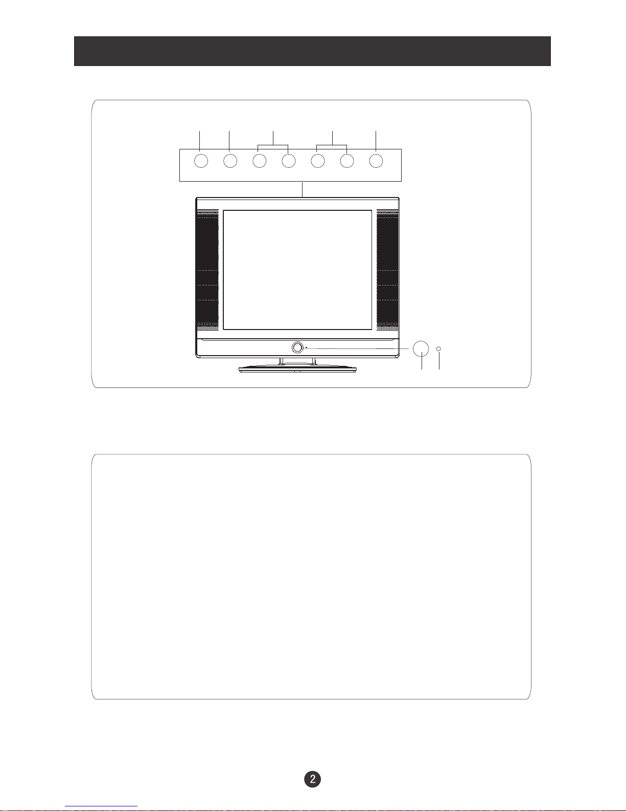
Front Panel Controls
Control Panel Function
TV/AV MENU VOL- VOL+ CH- CH+ POWER
2 3 4 5
1. Power supply switch
2.TV/AV PC/COMPONENT/AV/SV/TV/DVD
3. MENU Press to select the main menu
4. VOL- Volume down / Left orientation to adjust the item in the OSD
VOL+ Volume up / Right orientation to adjust the item/Press to enter
5. CH- TV channel down / to select the item in the menu
CH+ TV channel up / to select the item in the menu
6. Power indicator
Illuminates red in standby mode, illuminates green when the display is
turned on
7.Remote Sensor
Selects the input signals:
Receives the signals from the remote control
1
6
7
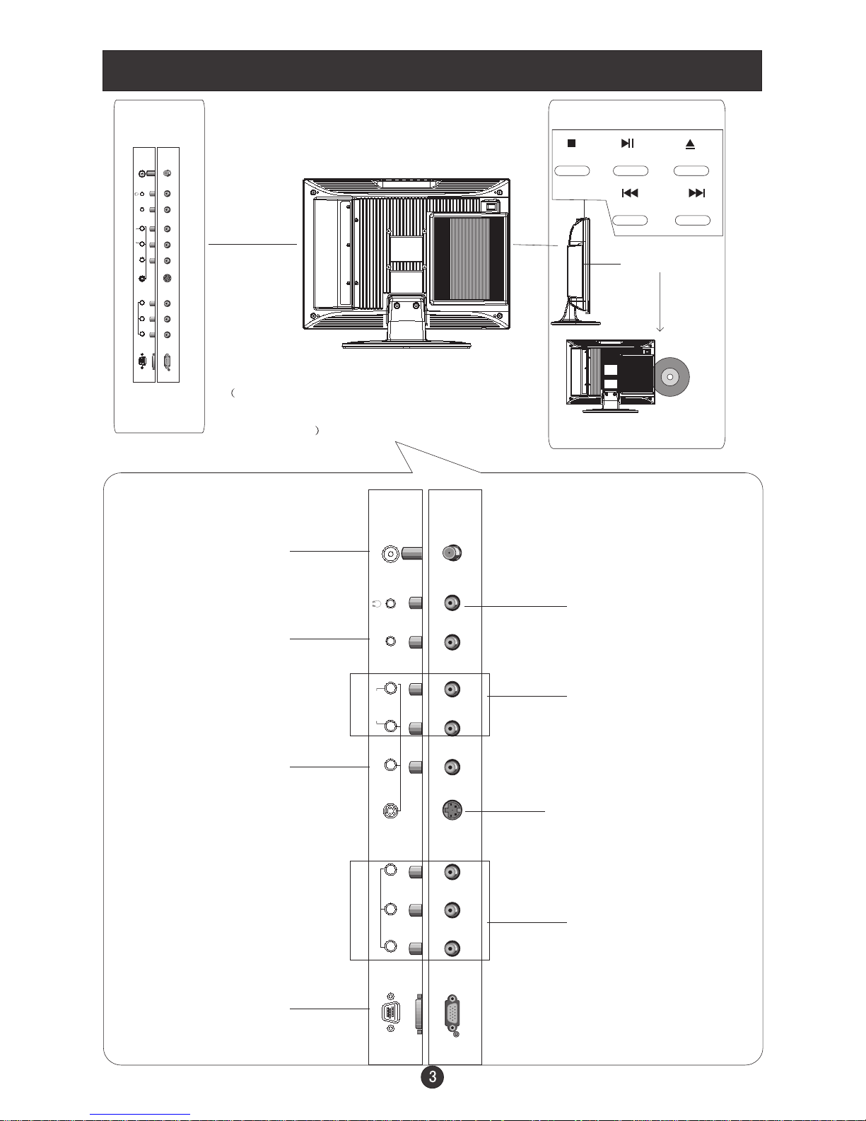
Connection Options
The above figure is for reference only,
connections may differ depending upon
the models
DVD
STOP PLAY/PAUSE OPEN/CLOSE
PREW NEXT
DVD insert
VGA Input
Connect to the VGA
15PIN analog output
connector of a PC
display card to use set
as a PC display
DVD/DTV Input
Connect a component
video/audiodevice to
these jacks
Video Input
Connect video output
from an external
device to this jack
AV/S-VIDEO/
COMPONENT Audio
Input
Connect audio output
from an external device
to these jacks
PC Audio Input
Connect the audio
output from the pc
to the audio input port
Earphone port
Antenna Input
Connect cable or
antenna signals to
the TV, either directly or through your
cable box.
S-Video Input
Connect S-Video out
from an S-Video device
to the jacks.
ANT IN
S-VIDEO
VGA IN
PC AUDIO IN
AUDIO IN
R
L
VIDEO IN
V
Pb
Pr Y
COMPONENT IN
ANT IN
S-VIDEO
VGA IN
PC AUDIO IN
AUDIO IN
R
L
VIDEO IN
V
Pb
Pr Y
COMPONENT IN

Features
Model
NO.
Functions
HLTDC19
1
TFT SAMSUNG
2
Screen size 19inch
3
Aspect ratio 4:3
4
Resolution 1280×1024
5
Brightness 300cd/m
2
6
Contrast(Darkroom) 700:1
7
Response time(ms) 8
8
Color system NTSC
9
NO. of preset channels 181
10
Picture mode Yes
11
Angel of view H:150°/ V:135°
12
Color display 16,777,216
13
Color level 16
14
OSD languages ENGLISH,FRENCH, SPANISH
15
AV stereo Yes
16
Surrounding sound No
17
Audio system M
18
Bass Yes
19
Balance Yes
20
Sound mode Yes
21
Mute Yes
22
BTSC Yes
23
AV input Yes
24
AV output No
25
Y CB CR Yes
26
Y PB PR Yes
27
S-video jack Yes
28
TV in Yes

Model
NO.
Functions
HLTDC19
29
D-SUB jack Yes
30
DVI socket
No
31
SCART socket
No
32
Ear-Phone Out
Yes
33
CCD,V-CHIP
Yes
34
Semitransparent menu
Yes
35
ZOOM
No
36
16:9 mode
No
37
Child Lock
Yes
38
Quick View
Yes
39
NO. of built-in speakers
2
40
Audio output power(Built-in)(W)
2*1.5
41
Total power input(W)
80
42
Voltage range(V)
120
43
Power frequency(Hz)
60
44
Time of sleep timer(MINS)
240
45
Approval
UL
46
Suitable market
U.S.
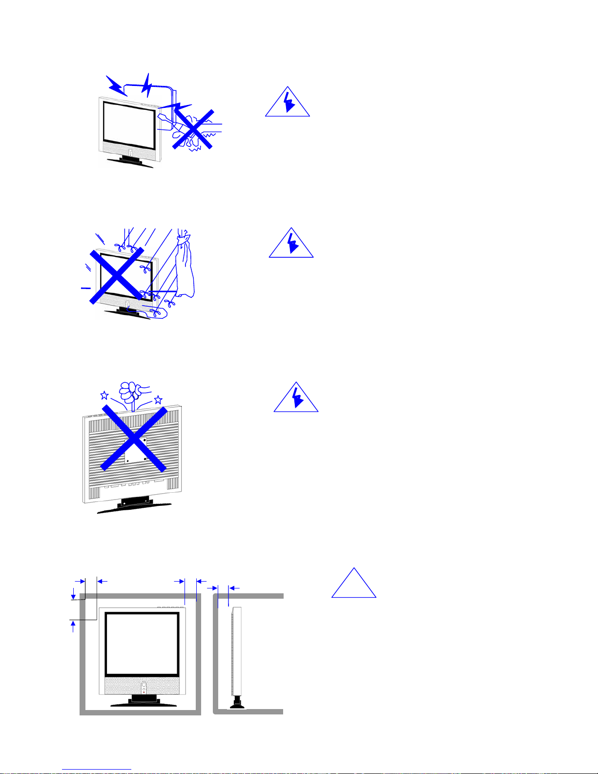
Warnings and Cautions
Warning
High voltages are used in the operation of this product.
Do not romove the cabinet back from your set. Refer
servicing to qualified service personnel.
Warning
To prevent fire or electrical shock hazard, Do not expose
the main unit to rain or moisture.
Warning
Do not drop or push objects into the television cabinet
slots or openings. Never spill any kind of liquid on the
television receiver.
Caution
If the television is to be built into a
compartment or similarly enclosed, the
minimum distances must be maintained.
Heat build-up can reduce the service life of
your television, and can also be dangerous.
!
Minimum
10c
20c
10c
5cm
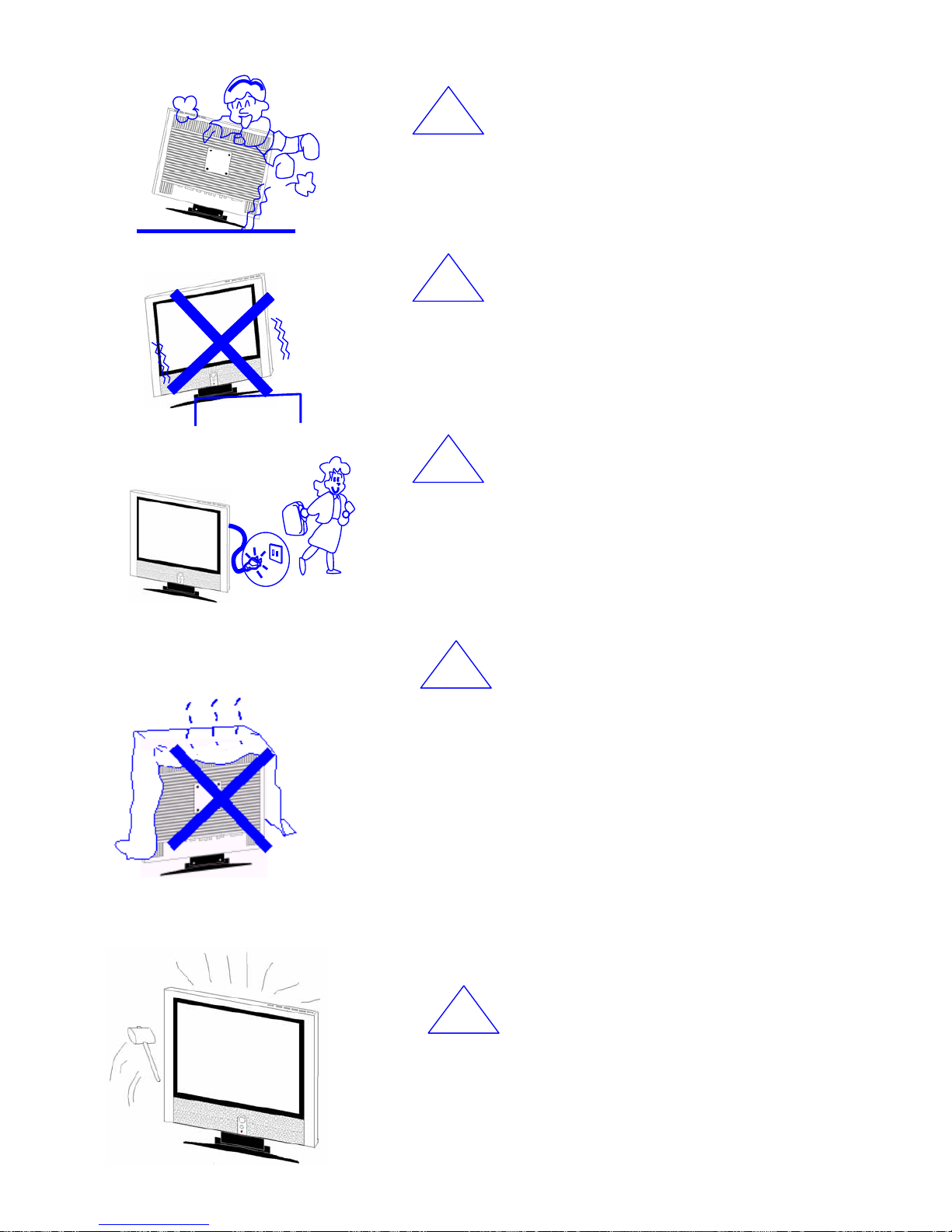
Caution
Never stand on, lean on, push suddenly the product or its
stand. You should pay special attention to children to children.
Caution
Do not place the main unit on an unstable cart stand, shelf or
table. Serious injury to an individual, and damage to the
television, may result if it should fall.
Caution
When the product is not used for an extended period of time, it
is advisable to disconnect the AC power cord from the AC
outlet.
Caution
Avoid exposing the main unit to direct sunlight and other
source of the heat. Do not stand the television receiver
directly on other produces which give off heat. E. g. video
cassette players,Audio amplifiers. Do not block the
ventilation holes in the back cover. Ventilation is essential to
prevent failure of electrical component. Do not squash power
supply cord under the main unit.
Caution
The LCD panel used in this product is made of glass.
Therefore, it can break when the product is droppe d or
applied with impact. Be careful not to be injured by
broken glass pieces in case the LCD panel breaks.
!
!
!
!
!

REPLACEMENT OF MEMORY IC
1. MEMORY IC
This LCD TV uses memory IC. In the memory IC are memorized data for correctly operating the video and
sound circuits. When replacing memory IC, be sure to use IC written with the initial value of data.
2.CHECK MEMORY IC
(1) Power off
Unplug the ~120V power plug from ~120V power socket.
(2) Replace IC
Be sure to use memory IC written with the initial data values or blank memory IC.
(3) Power On
Plug the ~120V power plug into ~120V power socket. (If memory IC is blank, the program will take 25s to
initial memory IC.
(4) Check and set SYSTEM default value:
1) Press “DISPLAY” key, then press key “CCD”,"MTS/SAP”,"CCD”,"DISPLAY” on the Remote control
unit continuously for factory used.
2) The “Factory mode” will be displayed on the screen,
3) Check the setting value of the SYSTEM default value of Table below. If the vale is different, select
items by [CH-]&[CH+] keys and set value by [VOL-]&[VOL+] keys.
4) Press “EXIT” key and return to the normal screen.
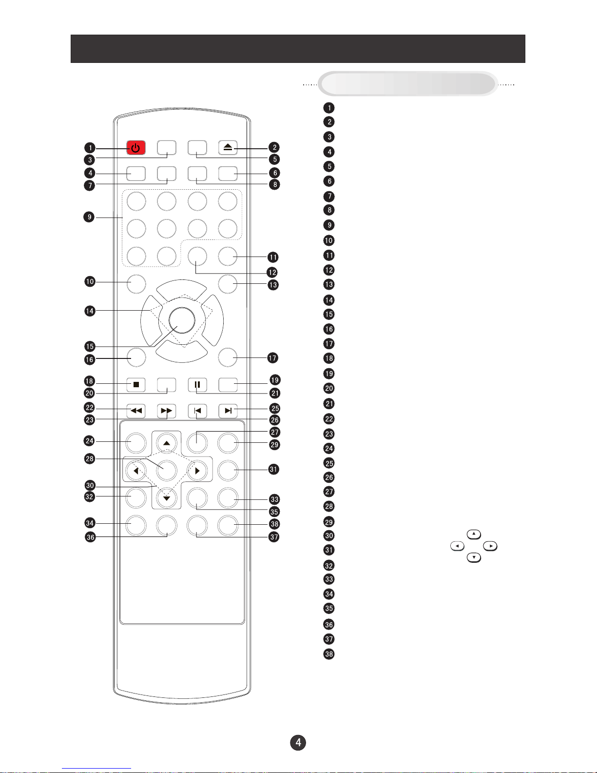
Remote Control Key Functions
When using the remote control, aim it
towards the remote sensor on the TV
Stand By
DVD Open/close
Scan
TV/DVD
Mute
Call Screen Display
Program Number
TV Sleep button
Volume/Channel Selection
MENU
DVD 10+
DVD STOP
DVD SUBTITLE
DVD SETUP
DVD PAUSE/STEP
DVD FAST REVERSE
DVD FAST FORWARD
DVD MENU
DVD NEXT
DVD PREVIOUS
DVD REPEAT
DVD PLAY/ENTER
DVD A-B REPEAT
DVD Cursor Move button
DVD SLOW
DVD ANGLE
DVD SEARCH
DVD TITLE/PBC
DVD PROGRAM
DVD CALL
TV/AV and input selection
Return to Previous Channel
CCD ( closed caption) On / Off
Adjust Picture Mode
Exit On Screen Display
Mode
Zoom Function
Select MONO,STEREO, SAP in NTSC system
DVD AUDIO
Buttons on the remote control
UP
DOWN
LEFT
RIGHT
POWER TV/DVD
OPEN/CLOSE
SCAN RECALL
DISPLAY
MUTE
1 2 3 4
5 6 7 8
99 00
CCD
P.STD
CH+
CH-
VOL
-
VOL
+
MENU
EXIT 10+
STOP
SETUP
PAUSE/STEP
REV FWD . PREV NEXT
D.MENU
REPEAT
A-B
PLAY/ENTER
SLOW
ANGLE
TITLE/PBC
SEARCH
ZOOM
D.CALL
PROGRAM
SUBTITLE
MTS/SAP
TV/AV
SLEEP
AUDIO
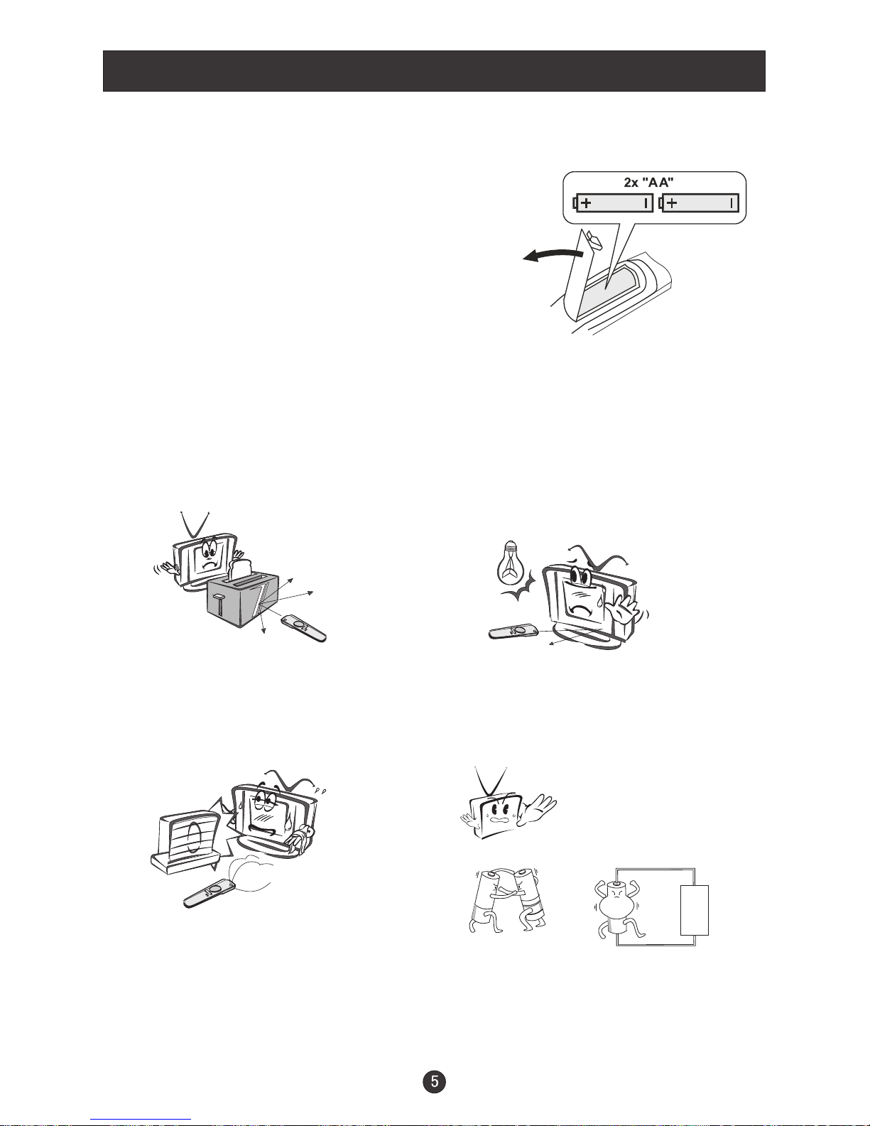
Remote Control
Installing Batteries
Remove the battery cover.
Insert two size AA batteries matching
the +/-polarities of the battery to the +/marks inside the battery compartment.
!
!
Precautions
Make sure that there is no
obstacle between the remote
controller and television set.
As strong light may interfere with the
signals, change your position to
operate the remote control if
the television cannot be turned
on or off as expected.
Keep the remote control
away from heat sources or
humid areas to ensure
effective performance of
the remote.
Make sure that two AA 1.5V alkaline
batteries are loaded. The batteries
must be of the same type, must be
inserted properly, and must not be
rechargeable.

ICs Function Description
1.UOC3
Function:TV signal processor with Teletext and Nicam
PIN SYMBOL DESCRIPTION
1 VSSP2 ground
2 VSSC4 ground
3 VDDC4 Digital supply to SDACs(1.8V)
4 VDDA3(3.3V) Supply(3.3V)
5 VREF_POS_LSL Positive reference voltage SDAC(3.3V)
6 VREF_NEG_LSL+HPL Negative reference voltage SDAC(0V)
7 VREF_POS_LSR+HPR Positive reference voltage SDAC(3.3V)
8 VREF_NEG_HPL+HRP Negative reference voltage SDAC(0V)
9 VREF_POS_HPR Positive reference voltage SDAC(3.3V)
10 XTALIN Crystal oscillator input
11 XTALOUT Crystal oscillator output
12 VSSA1 ground
13 VGUARD/SWIO
V-guard input/I/O switch (e.g.4mA current sinking
capability for direct drive of LEDs)
14 DECDIG Decoupling digital supply
15 VP1 1st supply voltage TV-processor(+5V)
16 PH2LF Phase-2 filter
17 PH1LF Phase-1 filter
18 GND1 Ground 1 for TV-processor
19 SECPLL SECAM OLL decoupling
20 DECBG Bandgap decoupling
21 EWD/AVL East-West drive output or AVL capacitor
22 VDRB Vertical drive B output
23 VDRA Vertical drive A output
24 VIFIN1 IF input 1
25 VIFIN2 IF input 2
26 VSC Vertical sawtooth capacitor
27 IREF Reference current input
28 GNDIF Ground connection for IF amplifier
29 SIFN1/DVBIN1 SIF input 1/ DVB input 1
30 SIFN2/DVBIN2 SIF input 2/ DVB input2
31 AGCOUT Tuner AGC output
32 EHTO EHT/over voltage protection input
33
AVL/SWO/SSIF/REFO/
REFIN
Automatic volume leveling/switch output/sound IF
input sub-carrier reference output/external reference
signal mixer for DVB operation
 Loading...