

Page 1
HW-09CV03
HW-12CV03
No.0010503559
Page 2

Contents
Parts Name ................................................................................................
Operation Guide .......................................................................................
Maintenance .............................................................................................
Cautions ......................................................................................................
Trouble Shooting ..........................................................................................
Installation Guide ...................................................................................
1
2-4
5-7
8
9
10-12
Page 3
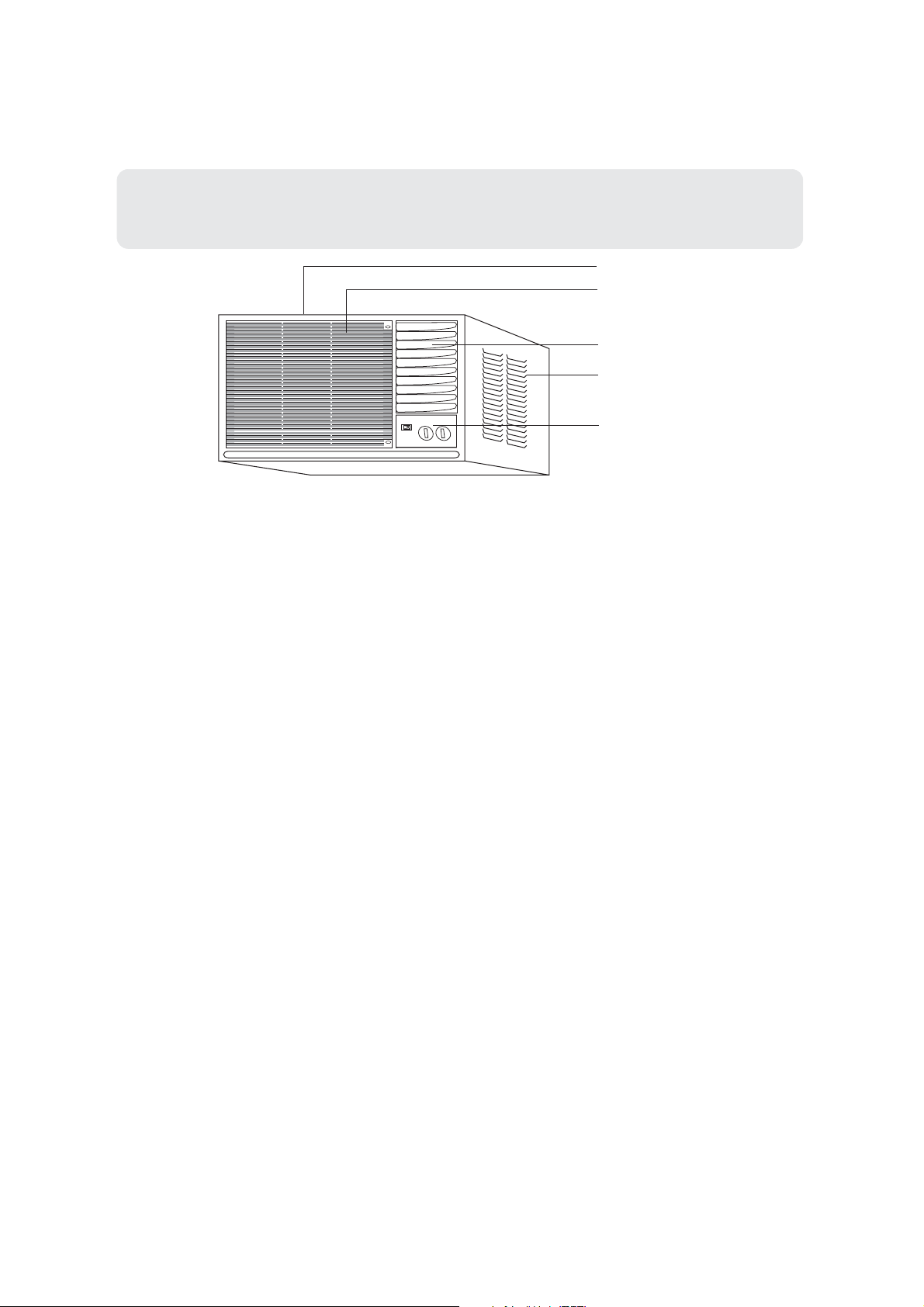
Parts Name
Front
Air inlet (indoor side)
Air outlet (indoor side)
Air inlet (outdoor side)
Operation
HW-09CV03
HW-12CV03
panel
panel
1
Page 4
Operation Guide
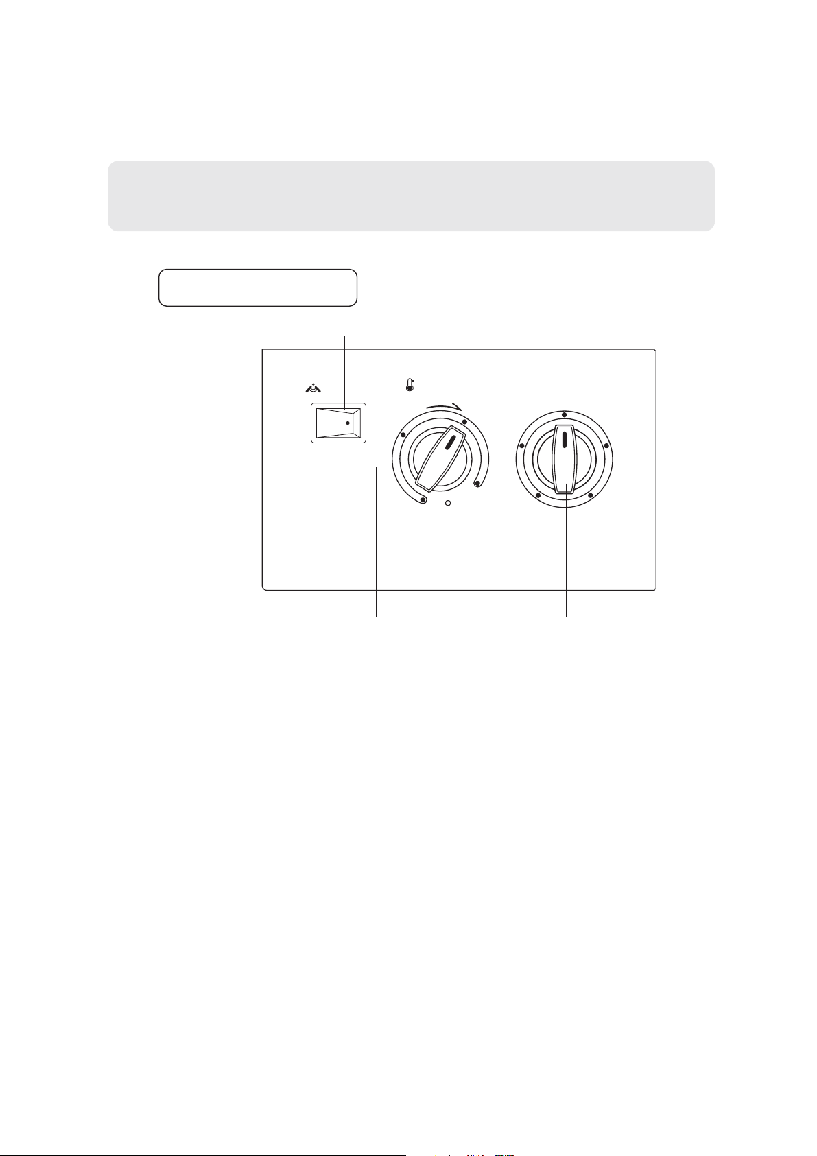
Operation panel
Auto swing switch
Auto swing
OFF ON
Wait 3 minutes before restarting.
3
Temp. setting
COOL
Test
1
run
Mode selection
LO
cool
OFF
HI
fan
HI
cool
6
LO
fan
9
Mode selection switchThermostat switch
2
Page 5
Operation Guide
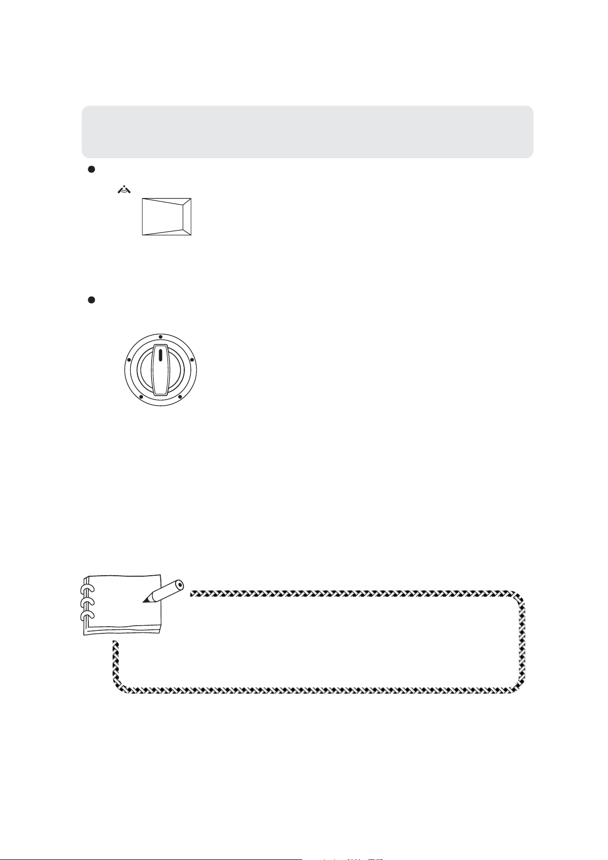
When the switch is set to " ON ", vertical louver will swing
from side to side, delivering gentle air thus making you
feel very comfortable.
When it is set to " OFF ", vertical louver will stop at
Auto swing switch
Auto swing
ONOFF
position.
Mode selection switch
OFF
LO
fan
LO
cool
HI
fan
HI
cool
Mode switch controls the fan motor
speed. Cooling speed or fan speed.
<1>
When set to "HI fan", fan motor runs at high
speed to blow out strong air.
<2>
When set to "LO fan", fan motor runs at low
speed to blow out gentle air.
<3>
When set to "HI cool", air-con will start
speedy cooling, blowing out strong air.
<4>
When set to "LO cool", air-con will start
cooling at low speed , blowing out gentle air.
<5>
When set to "OFF", air conditioner stops
running.
Hint
When mode selection switch is shifted to "HI fan" or"LO fan",
air-con will only blow out air without cooling. While the air
conditioner running, its mode selection shouldn't be shifted
frequently between "HI fan" and "HI cool", "LO fan" and "LO
cool".
3
Page 6

COOL
6
3
9
Test
1
run
4
Page 7

Page 8

Maintenance
Disposal of condensate
The drain hole on the bottom of the air conditioner will be clogged by a rubber
1.
stopper to make the condensate in the bottom tray be spattered onto the
condensation to raise efficiency of heat exchange. If the spattering sound disturbs
you, you can adopt the method illustrated below.
Condensate runs out from the drain hole on the back of the unit.
2.
Remove the rubber stopper from the drain hole on the bottom in order to make
the condensate run out. In this method the efficiency of air conditioner will be
slightly lowered.
In the both methods above, an extended hose (available on the market) can be
connected to the drain connecting pipe if necessary.
Extended
pipe (hose)
Cautions
Power cord: Be sure to use the exclusive power cord.
Change installation place: If air-con need to be changed to
another place please contact the dealer, who sold you the unit.
6
Page 9

Maintenance
Avoid opening door and window
unless necessary.
Use curtain or blind
Direct sunlight may reduce cooling
effect, always use window curtain.
Don't be exposed to cold air for
a long time.
Keep heat source away from
air conditioner.
Keep away from me
No entrance
Set temp. a little bit higher
before going to bed.
After unit stops, don't restart it
until 3 min. have elapsed.
OK! enjoy a
3-min nap
7
Page 10

Cautions
Don't hang clothes in the vicinity
of air inlet. This will decrease
cooling effect and cause abnormal
operation.
Go away!
Temperature should be set
properly when there are infant,
child, the aged or disabled
in room.
Baby has
gone sleep
had better adjust
suitable temp.
Before operating mode selection
switch, check if the air inlet or
outlet have been blocked.
For longer and trouble-free operation of the unit, pay special attention
to the following:
Install air-con at a place strong enough to support the unit.
Leave enough space around air inlet and outlet for better circulation.
Avoid places where flammable gas leaks.
Problems may occur if unit is installed in the following places:
Place where oil exists in the air including engine oil or seaside with
salt breeze blowing and hot spring area with sulphureous gas in the air.
8
Page 11

Trouble Shooting
Phenomenon
Doesn't work
No cool air or
poor cooling
Check the unit
Is plug firmly inserted?
Does fuse get burned?
Is there power?
Is thermostat switch
wrongly adjusted?
Is direct sunlight in
the room?
Is mode selection switch
set to "Hi fan" or "Lo fan"?
Is door or window left
open?
Resolution
Readjust power supply or
replace fuse.
Readjust the thermostat.
Use curtain or blind.
Shut doors and windows.
Are there any obstacles
blocking air inlet and
outlet?
Is there too much heat
source in the room?
Is air filter clogged? Clean it.
If problems can not be solved please pull out power plug and contact your dealer.
9
Remove the obstacles.
Remove the heat
source.
Page 12

Page 13

Installation instruction
The installation of air conditioner(only for reference)
1,Make the wall hole or window hole(see
Fig.1)
AB
HW-09CV03
HW-12CV03
2,Fix the prefabricated iron bracket to stable
positin by expansible screws.
3,Take out the conditioner and accessories
from the package.
4,Lift the back of the machine body silghtly .
You can see the drain hole at the back of
the bottom plate.Plug the black rubber lid
of the enclosed accessories into the hole(see
Fig.2).
5,Plug the drain elbow of the enclosed
accessories(with seal ring)into the drain
hole on the vertical wall at the back of the
bottom plate (see Fig.3).
530350
Iron bracket
Depth of the wall
Fig.1
Condenser
Rubber lid
Fig.2
6,If you need to lead the condensed water to
indicated position,pleae purchase a piece
of plastic pipe with inner diameter of 16,set
it on the drain elbow and tie it tightly.
7,After installation of all the accessories,put
the whole machine on the iron bracket .If
there is drain hose ,lead the hose to needed
position (see Fig.4).
Drain elbow
Drain hose
Fig.3
11
Page 14

Installation instruction
8,Fill any distance between the wall hole
and the machine body with flexible
sponge rubber strip to prevent the
entering of outer noise and the leaking
of the coolness.
Wall
9,After installation of the conditioner ,
insert the power plug into the outlet
Drain hose
and perform test-run.
Fig.4
The machine is adaptive in following situation
1. Applicable ambient temperature range:
Indoor side
Maximum:
Minimum:
D.B/W.B
D.B/W.B
Cooling
Outdoor side
2. If the supply cord is damaged, it must be replaced by the manufacturer or its service
agent or a similar qualified person.Power cable:3x1.5mm
3. After installation, the power plug should be easily reached.
4. The wiring method should be in line with the local wiring standard.
Maximum:
Minimum:
D.B/W.B
D.B
2
32°C/23°C
18°C/14°C
43°C/26°C
18°C
12
Page 15

Wiring Diagram
OPTIONAL
SWITCH
LO FAN
LO COOL
HI COOL
HI FAN
OFF
L
BR
Y/G
N
BL
POWER
R: RED
B: BLACK
BL: BLUE
BL
Y/G
TERMINAL
BLOCK
OR:ORANGE
Y:YELLOW
BR: BROWN
Y/G:YELLOW/GREEN
WIRING DIAGRAM
BOATSWITCH
R
4
1
2
3
0
BR
NOTE: BECAUSE OF DIFFERENT COMPRESSOR,
R
R
Y
B
THEDOTTEDPARTMAYNOTBEUSED.
SYNCHROMOTOR
M
FAN MOTOR
R
M
OR
C
THERMOSTAT
L
R
PROTECTOR
BL
FAN CAPACITOR
COMP.
C
S
M
R
7363749
BL
B
BL
COMP.
CAPACITOR
BL
TERMINAL
BLOCK
HW-09CV03
HW-12CV03
2600 980 5.0 330 1.2 Yes
3500 1300 6.3 380
1.5
523X564X342
523X564X342
33.5
39.5
Yes
Page 16

With 3 years warranty on all air- conditioner compressors, you have
peace of mind from the date of purchase
-
-
NATIONWIDE SALES AND SERVICES
MINNA,ILORIN,OSHOGBO,LOKOJA,
AKURE,SOKOTO,YOLA,MAKURDI,GUSAU,
sales office
7
-
-
-
2719790
 Loading...