

Page 1

WINDOW TYPE ROOM AIR CONDITIONER
OPERATION
MANUAL
HW-07CK03
HW-09CK03
Please read this operation manual
before using the air conditioner.
Please keep it attentively.
No.0010550222
Page 2

Contents
Contents
Part Name
Operation Guide
Maintenance
Trouble shooting
Installation Instructions
Installation Guide
The machine is adaptive in following situation:
1. Applicable ambient temperature range:
Cooling
............................................................................... 2
.............................................................................. 3
................................................................ 4-5
...................................................................... 6-8
................................................................... 9
......................................................... 10
............................................................. 11-12
Indoor
Outdoor
Maximum:
Minimum:
Maximum:
Minimum:
D.B/W.B
D.B/W.B
D.B/W.B
D.B
32oC/23oC
18oC/14oC
43oC/26oC
18oC
2. If the supply cord is damaged, it must be replaced by the
manufacturer or its serviceagent or a similar qualified person.
3. After installation, the power plug should be easily reached.
4. The wiring method should be in line with the local wiring standard.
2
Page 3

Parts Name
Machine body
Front panel
Air inlet (indoor side)
Machine body
Air outlet (indoor side)
Air inlet (outdoor side)
Display
Power plug
Air filter (inside)
panel
Operation panel
3
Page 4

Operation Guide
Auto air deflector switch
When the switch is set to " ", the indicator lights
up, and vertical louvers will swing from side to side,
delivering gentle air thus making you feel very
comfortable. When it is set to " ", the indicator
goes out, and the vertical louvers stop at any position.
Mode selection switch
Mode selection switch controls the fan motor
speed and cooling speed.
Hint
<1>
When set to " ", fan motor runs at high
speed to blow out strong air.
When set to " ", fan motor runs at low speed
<2>
to blow out gentle air.
<3>
When set to " ", air conditioner will start
cooling at low speed, blowing out gentle air.
<4>
When set to " ", air conditioner will start
speedy cooling, blowing out strong air.
<5>
When set to " ", air conditioner stops running.
When the mode selection switch is turned to " " or " " ,
the air conditioner will only blow out air without cooling.
If the mode selection switch is turned from cooling mode to fan
mode, do not turn it back until at least 3 minutes have elapsed.
4
Page 5
Operation Guide
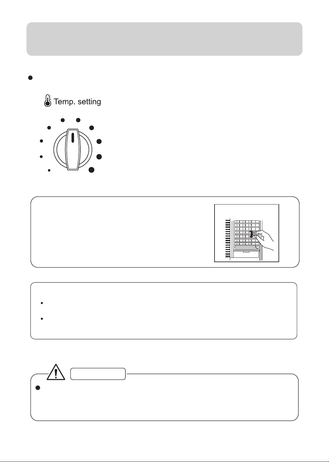
Thermostat switch
This switch controls the preset indoor temperature
to makethe air conditioner start or stop automatically,
so as to reduce power consumption and operate the
system both comfortably and economically.
Remarks:
Vertical Airflow Direction Vane (Airflow
direction adjustment Up-and-Down)
The Vertical Airflow Direction Vane is
manually controlled by positioning the
vane todischarge the air upward,
downward or straight out.
The compressor stops running when the
set temperature is reached but the fan
continues to operate to keep an even
indoor temperature.
Vertical airflow direction
Note:
It is advisable not to keep horizontal flap at downward position for a long
time in COOL or FAN mode, otherwise , condensate water might occur.
Don't move the vertical flap with hand in order to avoid the vertical flap
abnormal, using the remote controller to adjust the move of vertical flap.
CAUTION
In cooling mode, after you turn thermostat switch counter-clockwise,
do not turn it back until at least 3 minutes have elapsed.
Otherwise, the fuse may blow due to overload.
Do not exceed the selection range.
5
Page 6

Maintenance
Air filter cleaning (before cleaning, turn off the power)
When dirt accumulates on air filter, air circulation will be blocked, which causes poor
cooling. It is advisable to clean air filter every two weeks for longer operation.
Take out the air filter
1.
Press the concave parts on both sides at
the lower part of air inlet grille to open the
air inlet grille.
2.
As illustrated, remove the screw at the left
corner of the air filter.
3.
Hold the two white humps of filter mesh with
fingers (as illustrated) and take it out.
Air filter cleaning
1. Gently flap the dirt off the air filter.
2. Carefully wash air filter in warm water
(below 40*). To obtain better cleaning
effect, soap water or neutral detergent
may be used.
3. Flush air filter carefully with clean water
after removing dirt. Let it dry completely.
CAUTION
Power cord: Only to use an exclusive power cord.
Changing installation site: If the air conditioner needs to be changed to another
location, please contact the dealer that sold you the unit.
Screw Hump
Cleaning of the
air filter
6
Page 7

Maintenance
Disposal of the condensed water
Generally there are two methods available on disposal of the condensed water:
1. Block the bottom plate hole of the conditioner with rubber lid, install drain elbow on the
back hole and let the condensing water flow from the back hole of the conditioner. (See Fig.1 )
In this method, the accumulated condensed water in the bottom plate is hit by the fan onto the
heat exchanger, and evaporated and blown out from the machine. It can cool the heat
exchanger radiator more quickly, and improve the energy efficiency of the conditioner. But the
hitting noise by the fan at the outdoor side is relatively large.
2. Block the back hole of the conditioner with rubber lid and install drain elbow to the bottom
hole, which can make the condensed water flow out from the bottom plate. (See Fig.2)
If necessary the above two methods can both have extra pipe added on the drain elbow
(available on the market).
(Refer to P12 for choosing these two modes.)
drain elbow
Back hole
Fig.1
Rubber lid
Rubber lid
Back hole
drain elbow
Bottom plate hole
Fig.2
Cautions
Power cord: Be sure to use the exclusive power cord.
Change installation place: If air-con need to be changed to another
place please contact the dealer, who sold you the unit.
Bottom plate hole
7
Page 8

Maintenance
Avoid opening doors and windows
unless necessary.
Use curtain or blind
Direct sunlight may reduce cooling
effect, always use window curtain.
Don't be exposed to cold air for
a long time.
Keep heat source away from
air conditioner.
Set temp . a little bit higher
before going to bed.
Proper
temperature
After unit stops, don't restart it
until 3 min. have elapsed.
OK! Enjoy a
3-min nap
8
Page 9

Troubleshooting
Doesn't work
Is plug firmly inserted?
Is there power failure?
Readjust power supply.
Replace fuse.
Readjust the thermostat.
No cool air or
poor cooling
Does fuse get burned?
Is thermostat switch
wrongly adjusted?
Is there any direct
sunlight in the room?
Are doors or windows
left open?
Are there any obstacles
blocking air inlet and
outlet?
Is air filter clogged?
Use curtain or blind.
Shut doors and windows.
Remove the obstacles.
Clean it.
Remove the heat source
Is there too much heat
source in the room?
If problems can not be solved
please pull out power plug and
contact your dealer.
9
Page 10

Installation Instructions
Don't hang clothes in the vicinity
of air inlet. This will decrease
cooling effect and cause abnormal
operation.
Go away!
Temperature should be set
properly when there are infant,
child, the aged or disabled
in the room.
Baby has
gone sleep,
better to adjust
suitable temp.
Before operating mode selection
switch, check that if the air inlet
or outlet have been blocked.
For longer and trouble-free operation of the unit, pay special attention to
the following:
Install air-con at a place strong enough to support the unit.
Leave enough space around air inlet and outlet for better circulation.
Avoid places where flammable gas leaks.
Problems may occur if unit is installed in the following places:
Place where oil exists in the air including engine oil or seaside with
salt breeze blows and hot spring area with sulphurous gas in the air.
10
Page 11

Installation Guide
Selection of the installation position
1. The air-conditioner is better installed in shadow or in a place with short
period of sunshine. In case the air-conditioner is installed at the point
exposed directly to the sunshine, it should be protected from the direct
sunlight as possible in order to avoid the long time of direct sunlight
otherwise its performance will be lowered. (As illustrated in Fig. 1).
2. For the convenience of operation, it is recommended that air-conditioner
be installed at least at the height of 760-1300 mm above the floor and no obstacles
before it for a free airflow.
3. The shutters at both sides and the top of air-conditioner should be
protruded outdoors free from being blocked by wall, window, etc.
4. The back of air-conditioner should be kept over 500mm from the
obstacles (for example, wall, etc.) (As illustrated in Fig. 2).
5. To have an efficient drainage, the back part of the air-conditioner should
be inclined downward by 5-10mm (As illustrated in Fig. 3).
cover
support
fig.1
The enclosed accessories of the conditioner are:
Name
Manual
>500mm
fig.2 fig.3
Drain elbow Rubber lid
Figure
Quantity
1 11
5-10mm
11
Page 12

Installation Guide
Installation of air-conditioner (only for reference)
1. Make the wall hole or window hole (see Fig.1).
2. Fix the prefabricated iron frame to stable
position by expansible screws.
3.Take out the conditioner and accessories
from the package .
4. If user need to retain the condensate in the bottom
plate, can block the bottom hole with rubber lid and
as illustrated in Fig. 2, install drain elbow to back
hole of the air-conditioner, and connect drainage
tube. If the user doesn't need to retain the
condensate in the bottom plate, can remove the
rubber lid on the bottom and install drain elbow,
connect drainage tube as illustrated in Fig. 3.
NOTE: When installing the rubber lid or drain elbow,
you have to rotate it 90 degree for locking it.
Similarly , you need to rotate it 90 degree contrarily
for drawing it.
Iron frame
350
450
Fig. 1
Width of the wall
Drain elbow
Fig. 2
Water outlet flexible
pipe(provide by user)
Condenser
5. If you need to lead the condensed water to
indicated position, please purchase a piece
of plastic pipe , set it on the drain elbow
and tie it tightly.
6. After installation of all the accessories, put
the whole machine on the iron frame. If
there's water outlet flexible pipe, lead the
pipe to needed position(see Fig.4).
7. Fill any distance between the wall hole and
the machine body with flexible sponge rubber
strip to prevent the entering of outer noise and
the leaking of the coolness.
8. After installation of the conditioner, insert the
power plug into the outlet and perform test-run.
12
Fig.3
Fig.4
Drain elbow
Water outlet flexible
pipe(provide by user)
Wall
Water outlet flexible
pipe(provide by user)
Page 13

*******
*****
HW-07CK03
HW-09CK03
************
*****
Page 14

**
* *
****
****
****
****
****
****
1.**********:
***
**
***
***
***
***
***
2
3
4-5
6-8
9
10
11-12
**/**
**/**
**/**
**
2.*************************
**************************
*********
3.******************
4.*****************
2
Page 15

****
**
***
********
**
********
********
****
***
********
****
*****
****** ******
3
Page 16

****
*****
******
********* **********
*********************
******************* *
*********************
********************
******
Mode selection
**
********** ********
<1>
************
********** ********
<2>
************
********** ********
<3>
**********
********** ********
<4>
**********
********** ********
<5>
*****
********** *** ***********
**
************************3***
**********
4
Page 17

****
******
**
*******************
*******************
*******************
***
* *
***********************************
**********************************
******
**
*******************3*************
******
***********
5
Page 18

****
****************
*************************************
***********************
*****
*****************
1.
**
*****************
2.
******************
*.
*****
*****
1.
***************
2.
***40**104 F**********
******************
******************
**
3.
*******************
*****************
*************
******************************
**
**
**
**
6
Page 19

****
******
******************
1. *********************************
******************
********************************
*********************
2. ************************************
********************************
************
************P12*
****
***
****
***
****
******
**
**
***
***
***
***
****
**********
*************************
*********
7
Page 20

****
*********** ***************
****
***************
***************
**
***************
*****
***************
***************
**
*****
******
***
8
Page 21

****
****
*******
*******
************
***
*****
******
*******
****
*******
***
*******
**
*******
******
********
********
********
********
********
***********
***
*****
*****
*****
**********
********
**
***********
***********
*******
9
Page 22

****
****************
****************
**
***
****************
*****************
*****
****
****
***************
**********
*******************************
****************************
*******************************
*********************
**********************************
**************************
10
Page 23

****
*******
1. *********************************
**********************************
2. ********************760~1300mm, *******
**********
3. ********************************
4. *******************500mm********2**
5. *******************5~10mm(**3**
**
***********
**
* *
* *
* *
*1
***
5-10mm
500mm**
*2 *3
****
1
1
***
1
11
Page 24

****
************
1.*********** 1**
2.******************
****
3.***************
4.*****************
*,*****************
****,****2**********
******, ************
******************
******************
******************
**3****************
*****
******************
****90*************
****90************
350
**
*2
**
450
****
****
****
****
***
**
5.*****************
*****************
*******
6.******************
******************
******** 4**
7.******************
******************
***
8.******************
***********
*3
**
****
****
****
*
****
****
 Loading...