

Page 1
SPLITTYPEROOMAIRCONDITIONER
OPERATION MANUAL
Contents
PARTS AND FUNCTIONS
OPERATION
MAINTENANCE
CAUTIONS
TROUBLE SHOOTING
Contenido
PARTES Y FUNCIONES
FUNCIONAMIENTO
MANTENIMIENTO
PRECAUCIONES
RESOLUCIÓN DE PROBLEMAS
1
2
5
6
7
8
9
12
13
14
Table des matières
ÉLÉMENTS ET FONCTIONS
UTILISATION
ENTRETIEN
MISES EN GARDE
DÉPANNAGE
15
16
19
20
21
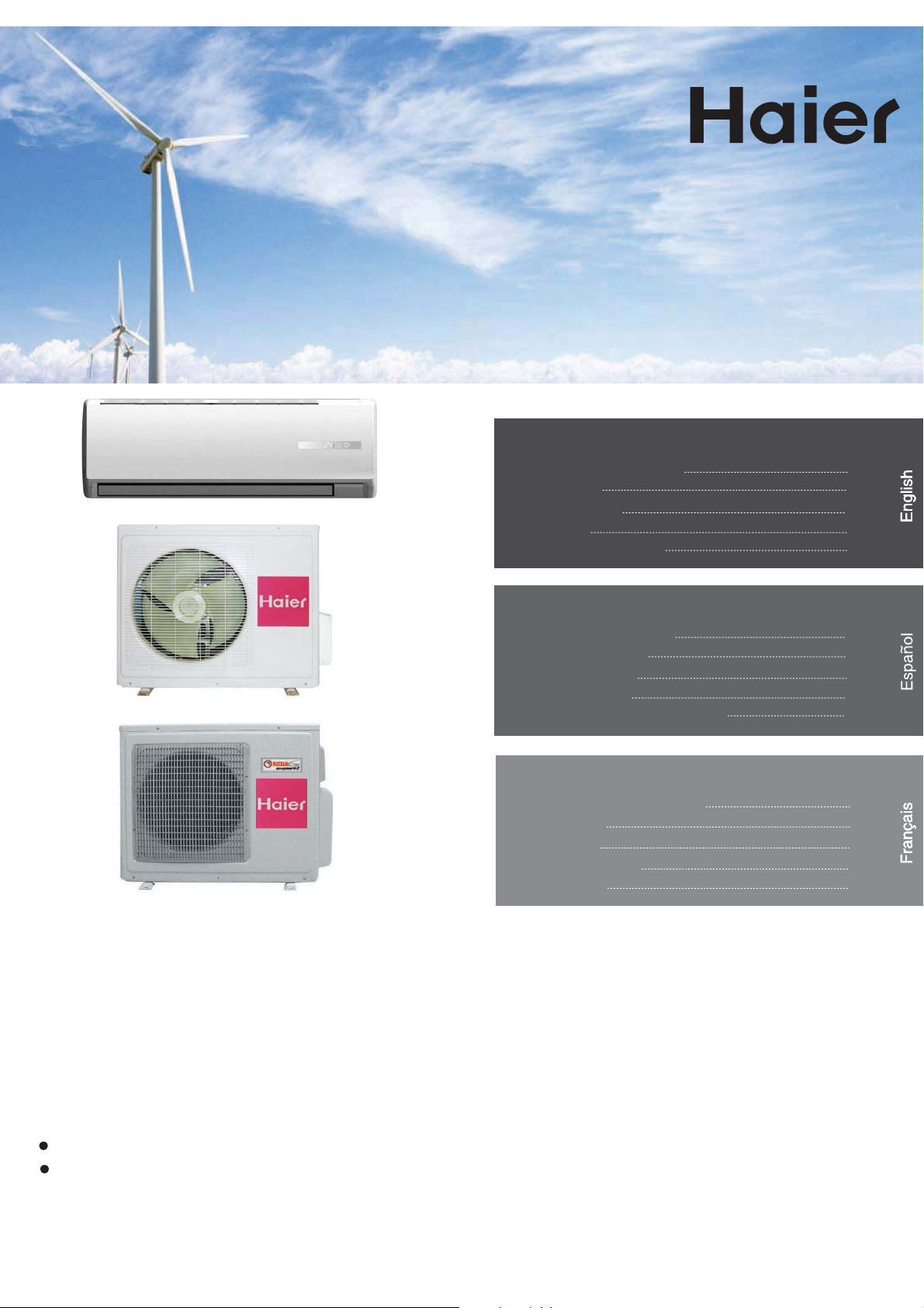
HSU09VHG(DB)-G
HSU12VHG(DB)-G
HSU18VHG(DB)-G
HSU24VHG(DB)-G
HSU109VHG-G
HSU-09HEG03/R2(DB)
Dual
HSU09VHG(DB)-W
HSU12VHG(DB)-W
HSU18VHG(DB)-W
HSU24VHG(DB)-W
HSU218VHG-W
2HUM18HC03/R2(DB)
HSU112VHG-G
AS12GS1ERA
Please read this operation manual before using the air conditioner.
HSU218VHG-W is variable-speed multi-split heat pump while others variable-speed mini-split.
Keep this operation manual for future reference.
Page 2

Page 3
Parts and Functions
Indoor Unit
Inlet
Front Cover
Outlet
Vertical louvers
(adjust left and
right air flow)
Horizontal louver
(adjust up and
down air flow
Don’t adjust it
manually)
The unit pictured above is for reference only.
Your product may appear different.
Display board
1
1
Signal receiver hole
2
ON/OFF display
3
Ambient temp.display
When receiving the remote
control signal, display the set
temperature will be shown in the
display. The room temperature is
displayed and this room
temperature is only for reference.
2
4
Note to the Auto restart function:
Press the sleep button ten times in five seconds
and enter the function after hearing four sounds.
Press the sleep button ten times within five
seconds and leave this function after hearing
two sounds.
Air Purifying Filter
Display
board
3
4
TIMER ON display
TIMER OFF display
SLEEP display
5
COOL\HEAT\DRY\AUTO display
(inside)
Emergency
Switch
5
Remote Control
1
2
3
4
5
9
10
11
12
13
14
15
16
17
1. Mode display
Operation mode
Remote controller
2. Signal sending display
3. SWING display
4.FAN SPEED display
LO MED HI
5. LOCK display
6.TIMER OFF display
TIMER ON display
7.TEMP display
8
Additional functions display
.
Operation mode
Remote controller
QUITE
SLEEP
Display
circulated
HEALTH
HEAT
AUTO
6
9. QUIET button
10. HEAT button
11. COOL button
7
12. AUTO button
13. FAN button
14. TIMER button
15. HEALTH button
8
16. LOCK button
18
Used to lock buttons and LCD display.
17. LIGHT button
Control the lightening and extinguishing
19
of the indoor LED display board.
20
18. POWER ON/OFF button
19. DRY button
21
20. TEMP button
21. SWING button
22
22. HOUR button
23
23. EXTRA FUNCTION button
Function:Fan Mode— Healthy
24
airflow upwarder — Healthy airflow
downwarder— Reset the healthy
25
airflow position — Right & left airflow
setting— A-B yard— 10℃ low
temperature heating— Sleep Mode—
NAFOTUA COOL DRY
Electrical Heating— Refresh Air—
Power — Fahrenheit/Celsius mode
shift on unit and remote
Remark:A-B yard, Right & left airflow
setting, 10℃ low temperature heating,
Electrical Heating, Refresh Air functions
are not available for this mini split series.
24.CANCEL/CONFIRM button
Function: Setting and cancel to the
timer and other additional functions.
25. RESET button
If the remote is not functioning properly,
use a pen point or similar object to
POWER
depress the button to reset the remote
Outdoor Unit
4
OUTLET
INLET
The unit pictured above is for reference only.
Your product may appear different.
CONNECTING PIPING AND ELECTRICAL WIRING
DRAIN HOSE
Healthy function is not available for some units.
Inserting the Battery
Remove the battery cover;
Then put on the cover again.
4
Note:
The distance from the remote to the receiver should be less than
23 feet (7 meters) with no obstructions.
Fluorescent lights or cordless telephones will reduce the range
of the remote.
If the display is dim the remote batteries may need to be replaced.
Remote malfunctions can sometimes be corrected by removing
the batteries for a few minutes and then replacing them.
Hint:
Remove the batteries if the unit won't be in use for a long period. If
there is any display after taking-out the batteries, just press reset key.
1
Insert the batteries as illustrated.
2
2 AAA batteries.
Be sure battery polarity is
3
correct
+ -.
1
Page 4
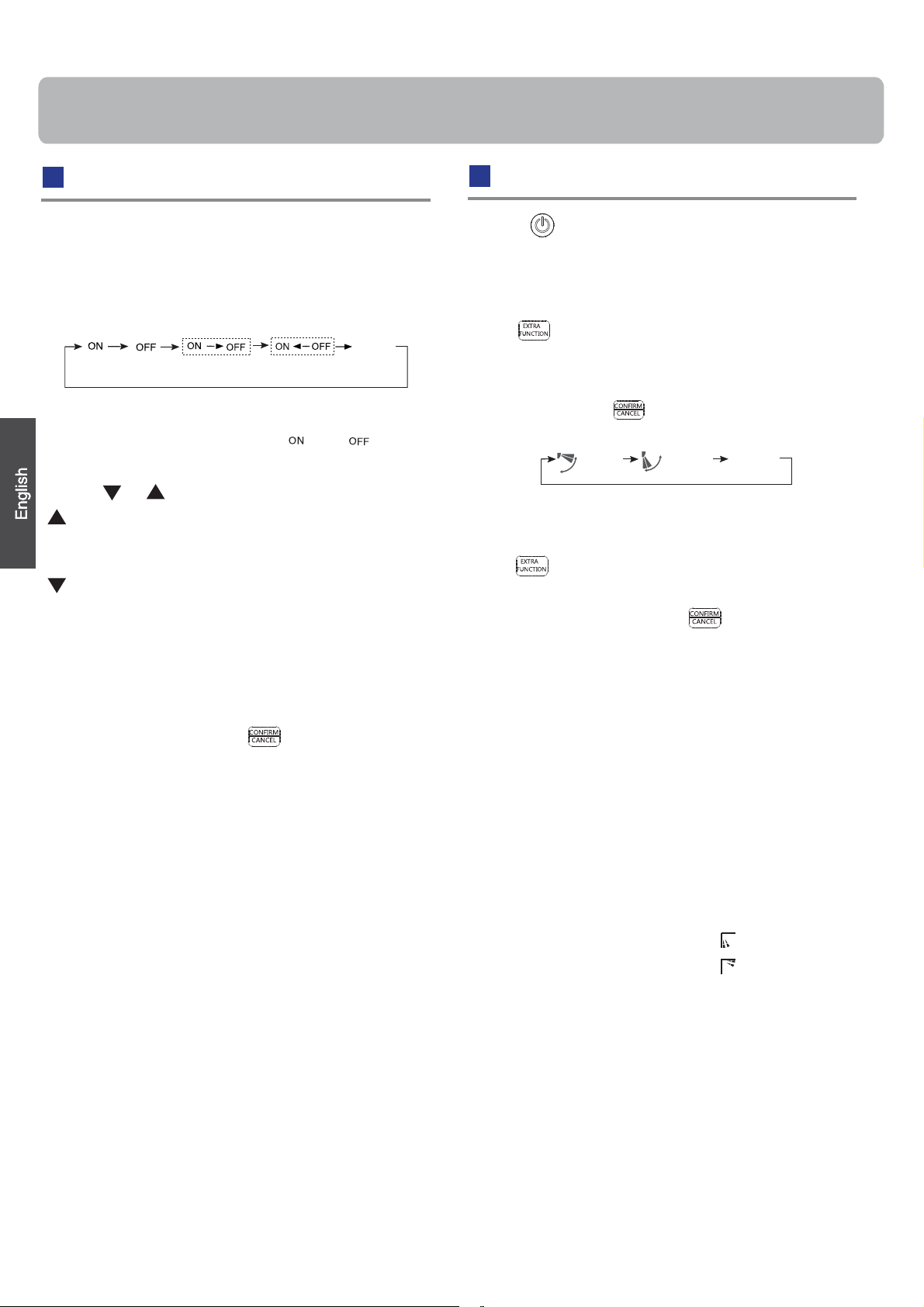
Operation
Basic Operation
AUTO
A
U
T
O
Remote controller
1. Unit start
Press ON/OFF on the remote controller, unit starts.
2.Select operation mode
COOL button:Cooling mode
HEAT button: Heating mode
DRY button: Dehumidify mode
3.Select temp.setting
Press
Every time the button is pressed, temp.setting
increase 1
increase rapidly
Every time the button is pressed, temp.setting
decrease 1
decrease rapidly
Select a desired temperature.
button
o
o
C / 2 F, if kept depressed, it will
o
o
C / 2 F, if kept depressed, it will
4.Fan speed selection
Press FAN button. For each press, fan speed
changes as
Remote controller:
follows:
LOW
MED HI
Emergency Operation and Test Operation
Emergency Operation:
Use this operation only when the remote controller is defective
or lost, and with function of emergency running, air conditoner
can run automatically in few seconds.
When the emergency operation switch is pressed, the unit
beeps once, which starts the operation.
When power switch is turned on for the first time and
emergency operation starts, the unit will run automatically in
the following modes:
Room
temperature
Above 23ą/73ȯ26ą/ 79ȯ
Below 23ą/73ȯ23ą/ 73ȯ
Designated
temperature
Timer
mode
No
No
Fan
speed
AUTO
AUTO
Operation
mode
COOL
HEAT
Beep
During emergency operation it is impossible to change the
settings of temp. and fan speed,It is also not possible to
operate in Timer or Dry mode.
Test Operation:
Test operation switch is the same as emergency switch.
Use this switch in the test operation when
the room
do not use it in the normal operation.
Continue to press the test operation
switch for more than 5 seconds.After
you hear two beeps, release your finger
from the switch: the cooling operation
starts with the air flow speed "HI".
Under this operation mode,the fan motor of indoor
unit will run in high speed.
temperature is below 16
ą/ 60ȯ
,
Beep-Beep
Air Flow Direction Adjustment
1.Status display of air flow
COOL/DRY:
HEAT:
Initial state
The air conditioner will be running at the speed shown
in the display.
When FAN is set to AUTO, the air conditioner
automatically adjusts the fan speed according to room
temperature.
Operation
Mode
AUTO
COOL
DRY
HEAT
FAN
2
Remote
Controller
Note
Under the mode of auto operation, air conditioner will
automatically select Cool or Heat operation according to
room temperature. When FAN is set to AUTO the air
conditioner automatically adjusts the fan speed according
to room temperature.
In DRY mode, when room temperature is 2 C/4 F degrees
less than the temperature set point, the unit will run
intermittently at LOW speed regardless of FAN setting.
In HEAT mode, warm air will blow out after a short
period of the time due to cold-draft prevention function.
When FAN is set to AUTO, the air conditioner automatically
adjusts the fan speed according to room temperature.
In FAN operation mode, the unit will not operate in COOL or
HEAT mode but only in
FAN mode. And temp. setting is disabled. In FAN mode,
sleep operation is not available.
FAN mode, AUTO is not available in
2.Left and right air flow adjustment
Move the vertical louver by a knob on air
(manual)
conditioner
to adjust left and right direction to achieve
stereoscopic air flow as the figure below.
Cautions:
stereoscopic air flow
When adjusting the louver by hand,turn off the unit.
o
o
When humidity is high,condensate water might occur
at air outlet if all vertical louvers are
adjusted to left or
right.
It is advisable not to keep horizontal louver at
downward position for a long time in COOL or DRY
mode ,otherwise, condensate water might occur.
Note:
When restarting the unit after it has been turned off,
the unit will keep the swing position before it stops
working.
Page 5
Operation
Sleep Operation
Press button to enter additional options, cycle
the display to , will flash. And then press
enter for sleep function.
Operation Mode
1. In COOL,DRY mode
1 hour after SLEEP mode starts,temp.will become
higher than temp.setting.After another 1 hour,temp.rises
O
O
C
by 1 / 2 F futher. The unit will run for an additional 6
hours then stops Temp. is higher than temp.setting so
that room temperature won’t be too low for your sleep.
SLEEP operation starts SLEEP operation stops
Approx.6hrs
O
O
1 hr
1 hr
Rises 1
Rises 1OC/ 2 F
O
C/ 2 F
O
1
C/2 F
In AUTO mode
3.
If the unit is running cooling, the sleep mode will follow
the function as in cool mode, while follow as in heat mode.
4. In FAN mode
It has no SLEEP function.
5.Fan Speed in Sleep Mode
When the unit is set to sleep mode, the fan speed
will be set to low speed and it cannot be changed.
Note
When TIMER function is set, the sleep function can’t be
set up .After the sleep function is set up, if user set up
TIMER function, the sleep function will be cancelled; the
O
machine will be in the state of timing-on.
Power/Quiet Operation
(1)
Power Operation
When you need rapid heating or cooling, you can use this function.
Press button to enter additional options, cycle the
display to , will flash,and then press ,enter to
power function. To cancel this function, please select a
different option.
Temp.setting
Unit stop
In COOL, DRY mode
In HEAT mode
2.
1 hour after SLEEP mode starts,temp will become 2
O
4 F lower than temp.setting.After another 1 hour,temp
decrease by 2
temp.
rises by 1 C / 2 F futher.The unit will run for an
O
O
C / 4 F futher.After more another 3 hours,
O
O
O
additional 3 hours then stops.Temp.is lower than temp.
setting so that room temperature won’t be too high for
your sleep.
Temp.setting
1 hr
1 hr
SLEEP
operation starts
Decreases 2OC/ 4 F
Decreases 2
Rises 1OC/ 2 F
3 hrs
O
O
O
C/ 4 F
3 hrs
O
SLEEP
operation stops
Unit stop
In HEAT mode
C /
(2)
Quiet Operation
You can use this function when silence is needed for rest or
reading.Press QUIET button, the remote controller will show
, and then achieve to the quiet function. To cancel this
function, press the QUIET button.
Note
Running the unit in QUIET mode for a long period may
cause the room temperature to not reach the set
temperature. If this occurs, cancel QUITE mode and set
the fan speed to a higher setting.
3
Page 6
Operation
Timer On/Off On-Off Operation
1.After unit starts, select your desired operation mode.
2.Press TIMER button to change TIMER mode. Every
time the button is pressed, display changes as follows:
Remote controller:
BLANK
0.5h
TIMER ON TIMER OFF TIMER ON-OFF
0.5h 0.5h
Then select your desired TIMER mode (TIMER ON or
TIMER OFF or TIMER ON-OFF). " "or " "will flash.
3.Press / button to set time.
Press the button for each time, setting time in the first
12 hours increased by 0.5 hour every time, after 12
hours,increased by 1 hour every time.
Press the button for each time, setting time in the first
12 hours decreased by 0.5 hour every time, after 12
hours,decreased by 1 hour every time.
It can be adjusted within 24 hours.
0.5h
TIMER OFF-ON
Healthy Airflow Operation
1.Press to start
Setting for comfortable conditions.
2.The setting of healthy airflow function
Press button to enter additional options,Press this
button continuously, the louvers location will cycle between
the following three locations, to choose the swing location
what you want, then button to confirm.
Healthy
airflow
upwarder
3.To cancel of the healthy airflow function
Press button to enter additional options,Press this
button continuously, the louvers location will cycle between
the three locations again, then button to cancel.
Healthy
airflow
downwarder
Present
position
4.Confirm timer setting
After adjusting the time,press button and confirm
the time the ON or OFF button will not flash any more.
5.Cancel timer setting
Press the timer button until the time display eliminated.
Hints:
After replacing batteries or a power failure happens, time
setting should be reset.
According to the Time setting sequence of TIMER ON or
TIMER OFF, either Start-Stop or Stop-Start can be achieved.
Notice: Do not direct the horizontal louver by hand. This
may cause the louver to run incorrectly and not match the
display. If the louver is not running correctly, stop the unit
for a minute and then restart and adjust remote
controller.
Note:
1.After setting the healthy airflow function, the position
louver is fixed.
2.In heating, it is better to select the
3.In cooling, it is better to select the
4.In cooling and dry, using the air conditioner for a long
time under the high air humidity, condensate water may
occur at the grille .
mode.
mode.
4
Page 7
Maintenance
For Smart Use ofThe Air Conditioner
Setting of proper room
temperature
Proper
temperature
Close doors and windows
during operation
During cooling operation
prevent the penetration
of
direct sunlight with
curtain or blind
If the unit is not to be used
for a long time, turn off the
power supply mainswitch.
OFF
Do not block the air inlet
or outlet
Use the timer effectively
Use the louvers effectively
Remote Controller Indoor Unit
Wipe the air conditioner by using a
soft and dry cloth.For serious stains,
Do not use water, wipe the remote
with a dry cloth. Do not use glass
cleaner or a chemicals.
use a neutral detergent diluted with
water.Wring the water out of the
cloth before wiping,then wipe off the
detergent completely.
Do not use the following for cleaning
Gasoline,benzine, thinner or cleanser
damage the coating of the unit.
ay
m
Hot waterover 40
cause
discoloring or deformation.
O
C(104OF) may
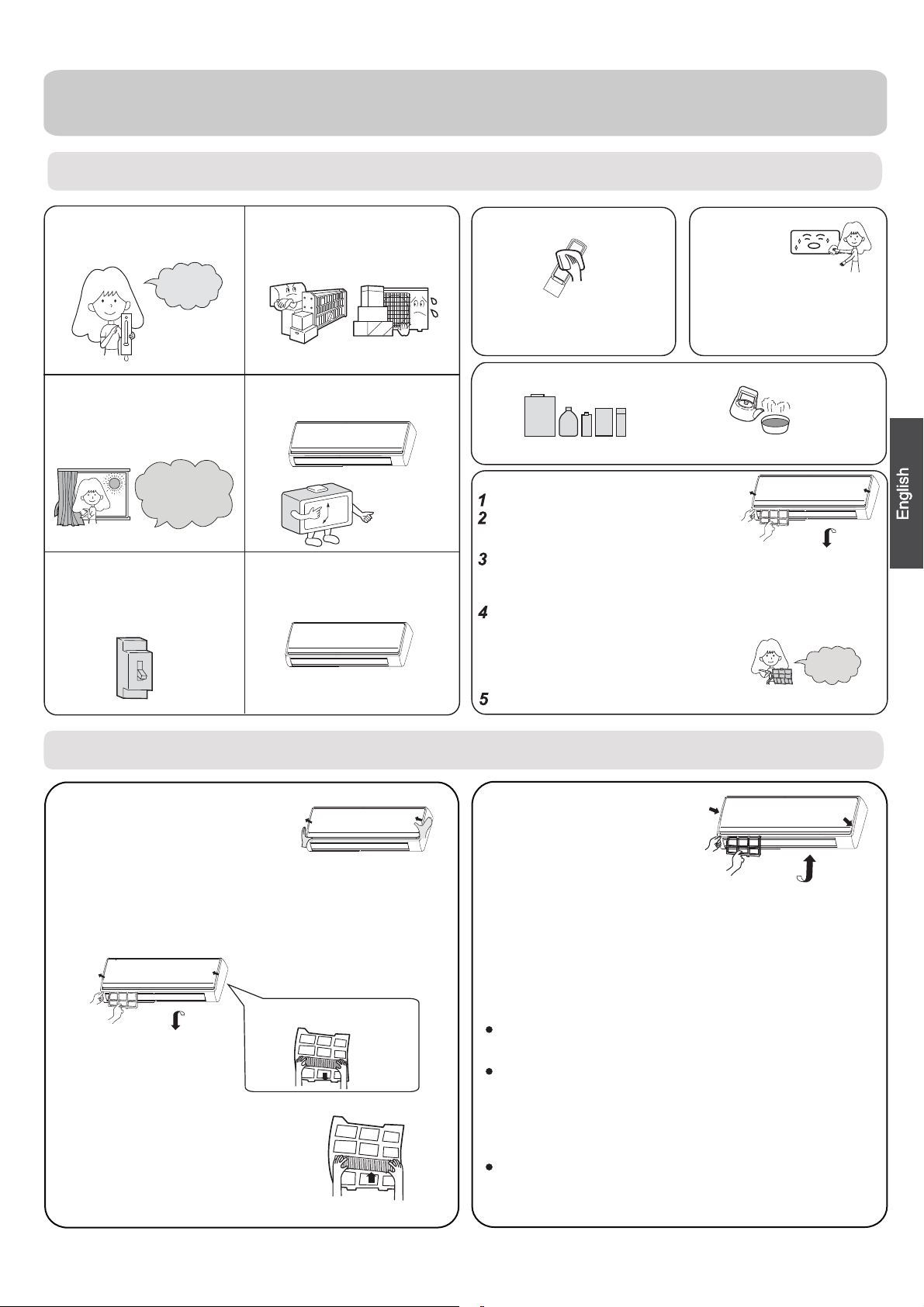
Air Filter Cleaning
Open the inlet grille by pulling it upward.
Remove the filter.
Push up the filter's center tab slightly until it is
released
Clean the filter.
Use a vacuum cleaner to remove dust, or wash the filter with
water.After washing, dry the filter completely before putting it back in
the unit.
Attach the filter.
Attach the filter correctly so that the "FRONT" indication
is
completely
and left filters are not
may cause defects.
Close the inlet grille.
from the stopper, and remove the filter do
facing to the front.Make sure that the filter is
fixed behind the stopper.If the right
attached correctly, that
wnw
ard.
Once every
two weeks
Replacement of Air Purifying Filter
1.Open the lnlet Grille
Prop up the inlet grille by using the
grille-support located an the right
side of the indoor unit.
2.Detach the Standard Air Filter
Slide the knob slightly up
release the filter, then withdraw it.
3.Attach Air Purifying Filter
Put air purifying filter into the
right and left filter frames.
ward to
Detach old Air Purifying Filter
4.Attach the standard air filter
(Necessar
y installation)
ATTENTION:
The white side of the photocatalyst air purifying filter
faces outside,and the black side faces the unit The green
side of the bacteria-killing medium air purifying filter faces
outside,and the white side faces the unit.
5.Close the Inlet Grille
Close the inlet grille securely
NOTE:
The photocatalyst air purifying filter will be solarized in fixed
time. In normal use, it will be solarized every 6 months.
The bacteria-killing medium air purifying filter will be used
for a long time,no need for replacement. But in the period
of using them ,you should remove the dust frequently by
using vacuum cleaner or flapping them lightly,otherwise ,
its performance will be affected.
Please keep the bacteria-killing medium air purifying filter
cool and dry. Avoid long term exposure to sunlight when not
in use as its ability to sterilize will be reduced.
5
Page 8

Cautions
WARNING
This system must be installed by a qualified HVAC professional.
Do not install the air conditioner by yourself improper installation may cause fire, water
leakage, personal injury or death.
WARNING
If something abnormal occurs immediately
stop the operation button and contact service
technician.
Connect to a single
circuit outlet.
Check proper
installation of the
drainage securely
OFF
Connect power supply cord
to the outlet completely
STRICT
ENFORCEMENT
Do not use power supply
cord in a bundle.
STRICT
ENFORCEMENT
Use the proper voltage
Take care not to damage
the power supply cord.
PROHIBITION
Do not start or stop the
operation by disconnecting
the power supply cord.
PROHIBITION
Do not place or store any objects on the
indoor unit.
Do not channel the air flow directly
at people.
1.Do not use extension cords or plug adapters.
2.
Do not install in the place where there is any
possibility of inflammable gas leakage around
the unit.
STRICT
ENFORCEMENT
PROHIBITION
PROHIBITION
3.Do not get the unit exposed
to vapor or oil steam.
Do not insert objects into the air inlet or outlet of
the outdoor unit..
Do not attempt to repair the
unit. Call for an authorized
service technician.
CAUTION
Take fresh air occasionally especially
when gas appliance is running at the
same time.
STRICT
ENFORCEMENT
PROHIBITION
PROHIBITION
Connect the earth
cable.
earthing
Do not operate the switch with
wet hand.
STRICT
PROHIBITION
Do not install the unit near a fireplace
or other heating apparatus.
PROHIBITION
Do not place animals or plants in
the direct path of the air flow
PROHIBITION
6
Install the outdoor unit securely on a
base.
Do not place any objects on or
climb on the outdoor unit.
ENFORCEMENT
PROHIBITION
PROHIBITION
Do not pour water onto the unit
for cleaning
Do not place flower vase or water
containers on the top of the unit.
PROHIBITION
PROHIBITION
PROHIBITION
Page 9

Trouble shooting
Cautions
Before calling for service, check the following
first.
Cause or check points
When unit is stopped, it won't restart
immediately until 3 minutes have
elapsed to protect the system.
When the electric plug is pulled out
and reinserted, the protection circuit
will work for 3 minutes to protect the
air conditioner.
During unit operation or at stop,
a swishing or gurgling noise may
be heard.At first 2-3 minutes after
unit start, this noise is more noticeable.
(This noise is generated by
refrigerant flowing in the system.)
Should there be a big noise from
air flow in unit operation, air
filter may be too dirty.
The system circulates any remaining
odors.
During COOL or DRY operation,
indoor unit may blow out mist.
This is due to the sudden cooling
of indoor air.
In DRY mode, when room temperature
becomes lower than temp.
setting+2
intermittently at LOW speed
regardless of FAN setting.
Is the power chord correctly position in
the outlet?
Is there a power failure?
Has a fuse or circuit breaker been
tripped?
Is the air filter dirty?
Normally it should be cleaned
every 14 days.
Are there any obstacles in front of
inlet and outlet?
Is temperature set correctly?
Are there some doors or
windows left open?
Is there any direct sunlight
through the window during the
cooling operation?(Use curtain)
Are there too many heat sources or too
many people in the room during cooling?
o
C,unit will run
Normal
performance
inspection
Multiple
check
Phenomenon
The system
does not restart
immediately.
Noise is heard
Odors are present
Mist or steam are
blown out.
In dry mode,
speed can’t be
changed.
Poor cooling
fan
Do not obstruct or cover the ventilation
conditoner.Do not put fingers
inlet/outlet and
Do not allow children to play with the air
case should children be
swing louver.
or any objects into the
allowed to sit on the outdoor unit.
grille of the air
conditioner
.In no
Specifications
The refrigerating circuit is a sealed system.
The machine is adaptive in following
1.Applicable ambient temperaturerange:
Indoor
Cooling
Heating
2. If the power supply cord is damaged, it
manufacturer
3.All electrical wiring must be done to applicable local and state codes.
4.An electrical outlet must be within distance of the indoor unit.
5. When replacing batteries, the batteries removed should be disposed
of properly.
6. Assure that the proper outlet is being used with the power cord.
The power plug and connecting cable
7.
attestation.
8. In order to protect the units,please turn off the unit first, wait 30
seconds and turn off the power.
Outdoor
Indoor
Outdoor
Outdoor
(INVERTER)
or its service agent.
Maximum:D.B/W.B
Minimum:D.B/W.B
Maximum:D.B/W.B
Minimum:
Maximum:D.B
Minimum:
Maximum:D.B/W.B
Minimum:D.B/W.B
Maximum:D.B/W.B
Minimum:D.B
situation
89.6 /73.4
67 /57
115 /75
D.B
D.B
67 /57
80.6
32
75 /65
19.4
75 /65
5
must be replaced
must have
by the
acquired the local
7
Page 10

REMOVAL PROCEDURE
Wall Mounted Type
DC Inverter FREE MATCH EK-Series
SERIES:35EK
WARNING
This service information is designed for experienced repair technicians only and is not designed for use by the general public.
It does not contain warnings or cautions to advise non-technical individuals of potential dangers in attempting to service a product.
Products powered by electricity should be serviced or repaired only by experienced professional technicians. Anyattempt to service or
Repair the product or products dealt with in this service information by anyone else could result in serious injury or death
All rights reserved. Unauthorized copying and distribution is a violation of law
Haier Group
2013 (Qingdao Haier Air Conditioner General corp. , Ltd)
Version V1 Date 2013-09-10
Page 11

1.Removal of Air Filter
Removal of procedure
1 Domestic Air Condition
Page 12

Removal of procedure
2
Please embed the air
filters into the unit along
the grooves as installation.
Please embed the
two
hooks on air filter
completely into the unit
during installation.
2 Domestic Air Condition
Page 13

2.Removal of front panel
until it is on the
horizontal position,
and then release the
pivots on both sides of
the unit to remove the
front panel.
Removal of procedure
Please close the panels
before start the removal
procedure of front grille.
one side to another to
release each axis.
3 Domestic Air Condition
Page 14

two
Removal of procedure
HOOKS
three
4 Domestic Air Condition
Page 15

3.Removal of horizontal flap
Removal of procedure
flap
flap
flap
flap
5 Domestic Air Condition
Page 16

4.Removal of Drain pan
Removal of procedure
6 Domestic Air Condition
Page 17

5.Removal of vertical blades and swing motor
Removal of procedure
7 Domestic Air Condition
Page 18

6.Removal of Electrical Box
Removal of procedure
8 Domestic Air Condition
Page 19

7.Removal of Heat Exchanger
Removal of procedure
9 Domestic Air Condition
Page 20

Removal of procedure
10
Domestic Air Condition
Page 21

8.Removal of Fan Rotor and Motor
Removal of procedure
11 Domestic Air Condition
Page 22

Removal of procedure
12 Domestic Air Condition
 Loading...