

Haier HSU-24HEA03/R2 User Manual

ROOM AIR CONDITIONER
WALL MOUNTED TYPE
INSTALLATION MANUAL
HSU-24HEA03/R2(DB)-I
5HDGWKLVPDQXDOEHIRUHLQVWDOODWLRQ
([SODLQVXIILFLHQWO\WKHRSHUDWLQJPHDQVWRWKHXVHU
NO.0010523241
DFFRUGLQJWRWKLVPDQXDO
Necessary Tools for Installation
1.Driver
2.Hacksaw
3.Hole core drill
4.Spanner(17,19 and 26mm)
Accessory parts
No. Accessory parts
1
2
3
4
Remote controller
R-03 dry battery
Mounting plate
Drain hose
Number
of
articles
1
2
1
1
5.Torque wrench(17mm,22mm,26mm)
6.Pipe cutter
7.Flaring tool
8.Knife
9.Nipper 12.Reamer
10.Gas leakage detector or
soap-and-water solution
11.Measuring tape
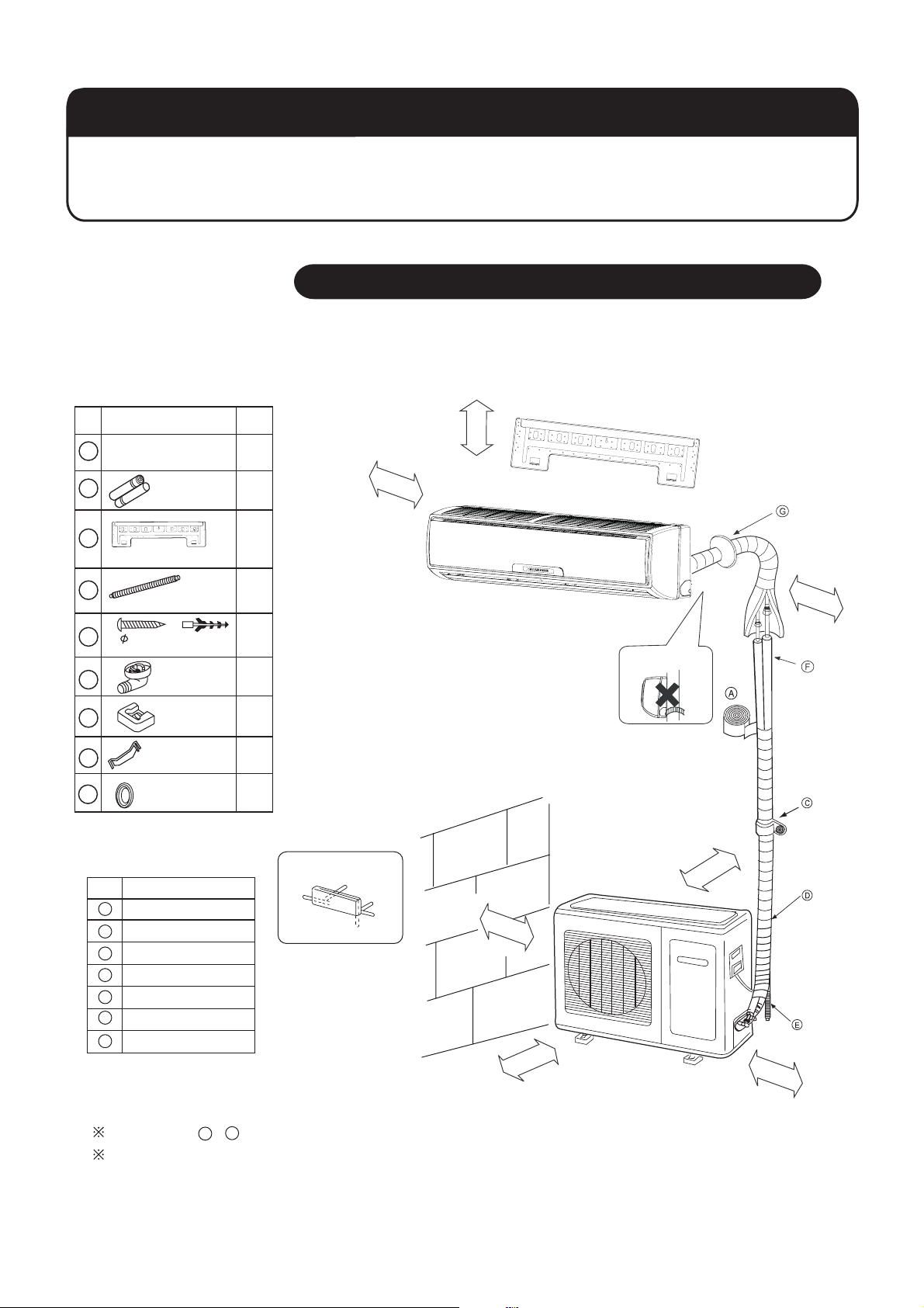
Drawing for the installation of indoor and outdoor units
The models adopt HFC free refrigerant R410A
5cm
n
a
h
t
e
r
o
m
m
o
r
e
t
h
a
n
10cm
m
ro
te
h
a
n
10cm
5
4X25
Screw
6
7
8
9
Plastic cap
Drain-elbow
Cushion
Pipe supporting plate
Cover
Optional parts for piping
Mark
A
B
C
D
E
F
G
Parts name
Non-adhesive tape
Adhesive tape
Saddle(L.S) with screws
Connecting electric cable
for indoor and outdoor
Drain hose
Heating insulating material
Piping hole cover
4
1
4
1
1
Arrangement of piping directions
Left
Rear left
Below
Rear
right
Right
Attention must be paid to
the rising up of drain hose
10cm
n
a
h
t
e
r
o
m
m
o
r
e
t
h
a
n
10cm
60cm
n
a
h
ter
om
om
r
e
t
h
a
n
15cm
A
The marks from to in the figure are the parts numbers.
G
The distance between the indoor unit and the floor should be
more than 2m.
1
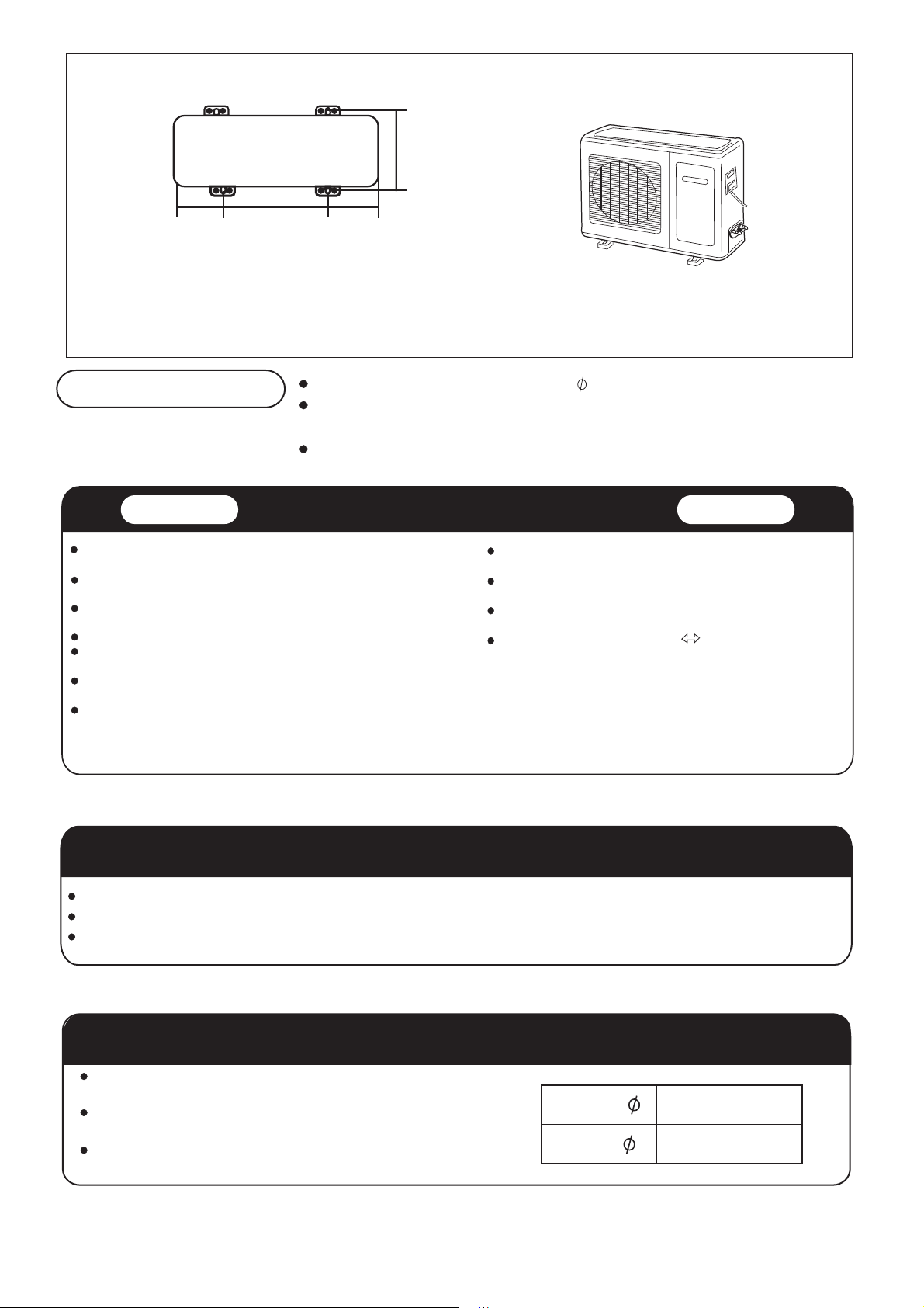
58
3
18
5
184
Floor fixing dimensions
of the outdoor unit
(Unit:mm)
Fixing of outdoor unit
Indoor Unit
Place, robust not causing vibration, where the body can be supported
sufficiently.
Place, not affected by heat or steam generated in the vicinity, where
inlet and outlet of the unit are not disturbed.
Place, possible to drain easily, where piping can be connected with the
outdoor unit.
Place, where cold air can be spread in a room entirely.
Place, nearby a power receptacle, with enough space around. (Refer
to drawings).
Place where the distance of more than lm from televisions, radios,
wireless apparatuses and fluorescent lamps can be left.
In the case of fixing the remote controller on a wall, place where the
indoor unit can receive signals when the fluorescent lamps in the room
are lightened.
Fix the unit to concrete or block with bolts( 10mm) and nuts firmly and horizontally.
When fitting the unit to wall surface, roof or rooftop, fix a supporter surely with nails
or wires in consideration of earthquake and strong wind.
If vibration may affect the house, fix the unit by attaching a vibration-proof mat.
Selection of Installation Place
Outdoor Unit
Place, which is less affected by rain or direct sunlight and is
sufficiently ventilated.
Place, possible to bear the unit, where vibration and noise are
not increased.
Place, where discharged wind and noise do not cause a
nuisance to the neighbors.
Place, where a distance marked is available as illustrated
in the above figure.
Power Source
Before inserting power plug into receptacle, check the voltage without fail. The power source is the same as the corresponding name plate.
Install an exclusive branch circuit of the power.
A receptacle shall be set up in a distance where the power cable can be reached. Do not extend the cable by cutting it.
Selection of pipe
To this unit, both liquid and gas pipes shall be insulated
as they become low temperature in operation.
Use optional parts for piping set or pipes covered with
equivalent insulation material.
The thickness of the pipe must be 0.8mm at least.
2
Liquid pipe( )
Gas pipe( )
9.52mm(3/8")
15.88mm(5/8")
Ind
it
oor un
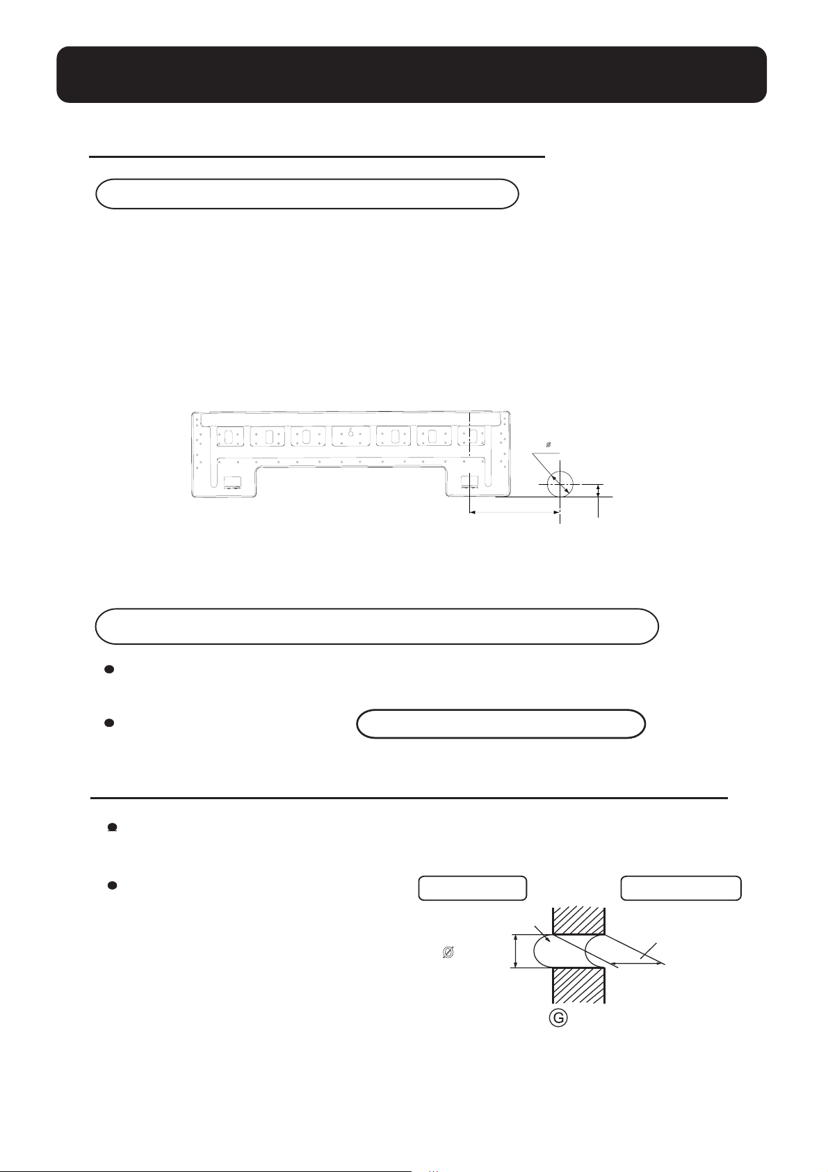
1.Fitting of the Mounting Plate and Positioning of the wall Hole
When the mounting plate is first fixed
1.Carry out, based on the neighboring pillars or lintels, a proper leveling for the plate to be
fixed against the wall, then temporarily fasten the plate with one steel nail.
2. Make sure once more the proper level of the plate, by hanging a thread with a weight from
the central top of the plate, then fasten securely the plate with the attachment steel nail.
3. Find the wall hole location A using a measuring tape
B= 83mm
A=145mm
mm03
When the mounting plate is fixed side bar and lintel
Fix to side bar and lintel a mounting bar, Which is separately sold, and then fasten
the plate to the fixed mounting bar.
Refer to the previous article, " When the mounting plate is first fixed ", for the
position of wall hole.
2.Making a Hole on the Wall and Fitting the Piping Hole Cover
Make a hole of 83 mm in diameter,
slightly descending to outside the wall.
Install piping hole cover and seal it
off with putty after installation
Indoor side
Wall hole
83mm
Outdoor side
Thickness
of wall
(Section of wall hole)
3
Piping hole pipe
Indoor unit
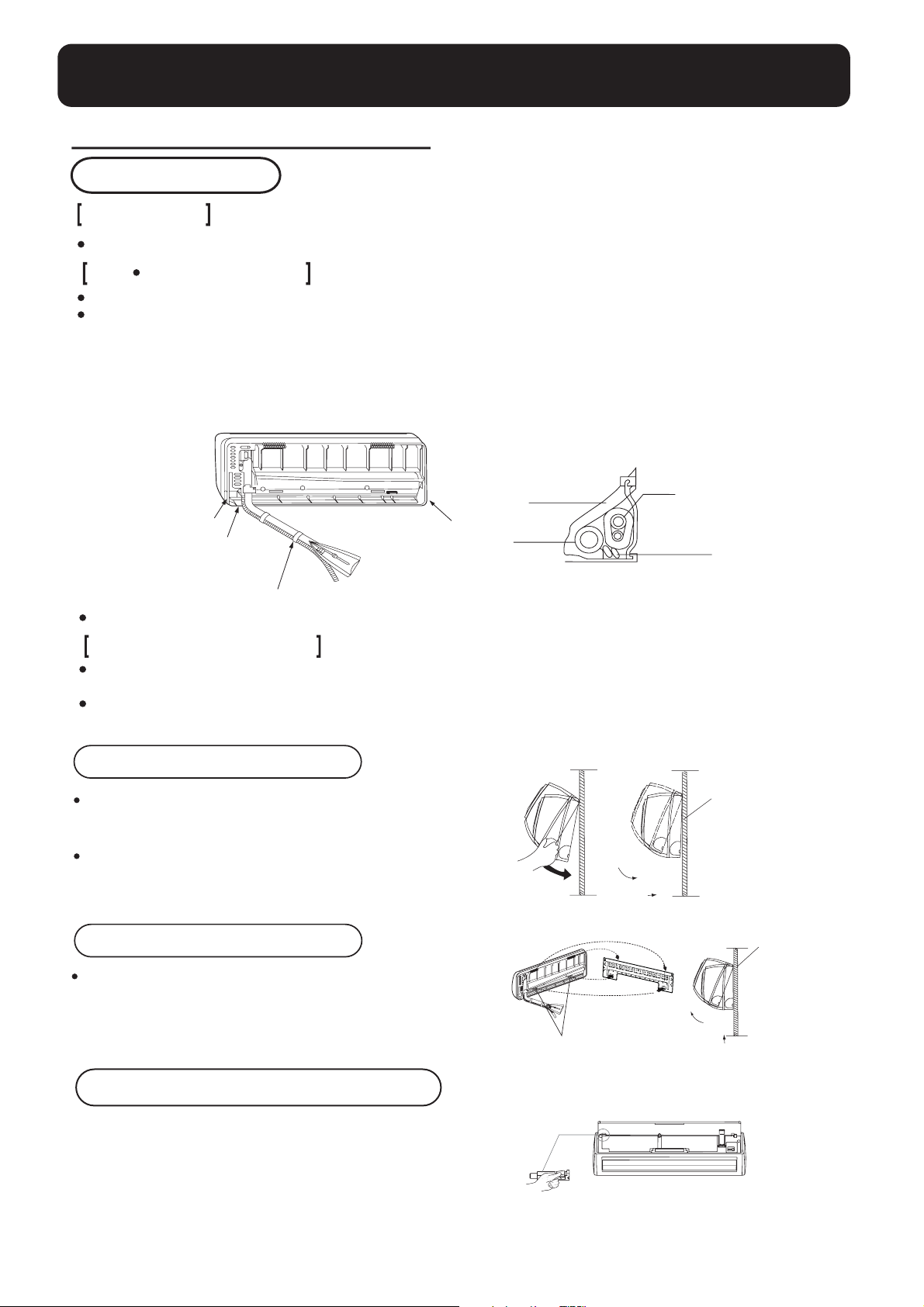
3.Installation of the Indoor Unit
Drawing of pipe
Rear piping
Draw pipes and the drain hose, then fasten them with the adhesive tape
Left Left-rear piping
In case of left side piping, cut away, with a nipper, the lid for left piping.
In case of left-rear piping, bend the pipes according to the piping direction to the mark of hole for left-rear
piping which is marked on heat insulation materials.
1. Insert the drain hose into the dent of heat insulation materials of indoor unit.
2. Insert the indoor/outdoor electric cable from backside of indoor unit, and pull it out on the front side, then
connect them.
3. Coat the flaring seal face with refrigerant oil and connect pipes.
Cover the connection part with heat insulation materials closely, and make sure fixing with adhesive tape
Heat insulation
material
Lid for right piping
Lid for under piping
Fix with adhesive tape
Indoor/outdoor electric cable and drain hose must be bound with refrigerant piping by protecting tape.
Lid for left piping
Drain hose
Piping
Indoor/outdoor
electric cable
Other direction piping
Cut away, with a nipper, the lid for piping according to the piping direction and then bend the pipe according
to the position of wall hole. When bending, be careful not to crash pipes.
Connect beforehand the indoor/outdoor electric cable, and then pull out the connected to the heat insulation
of connecting part specially.
Fixing the indoor unit body
Hang surely the unit body onto the upper notches of the
mounting plate. Move the body from side to side to verify
its secure fixing.
In order to fix the body onto the mounting plate,hold up
the body aslant from the underside and then put it down
perpendicularl
y.
mounting plate
Unloading of indoor unit body
When you unload the indoor unit,please use your hand to arise
the body to leave agraffe,then lift the bottom of the body outward
slightly and lift the unit aslant until it leaves the mounting plate.
Easily-demount cleaning of indoor unit
Inlet grille can be taken down
Open the inlet grille,press the button of unlock in the left,then push
it out of the socket and take out the inlet grille.
4
mounting plate
agraffe
 Loading...