

Haier HSU218VHG-W, 2HUM18HC03/R2, 2HUM18HC03/R2DB Installation Manual
Preparation
Necessary Tools for Installation Procedure for Selecting the Location
● Drill ●
● Nipper ●
● Saw
● Hole 2 3/4 ●
● Vacuum pump ●
●●
●
● Torque wrench
(17mm,22mm,26mm) ●
● Pipe cutter
● Flaring tool ●
● Knife ●
● Measuring tape
● Reamer NOTE: Cannot be installed hanging from ceiling or stacked.
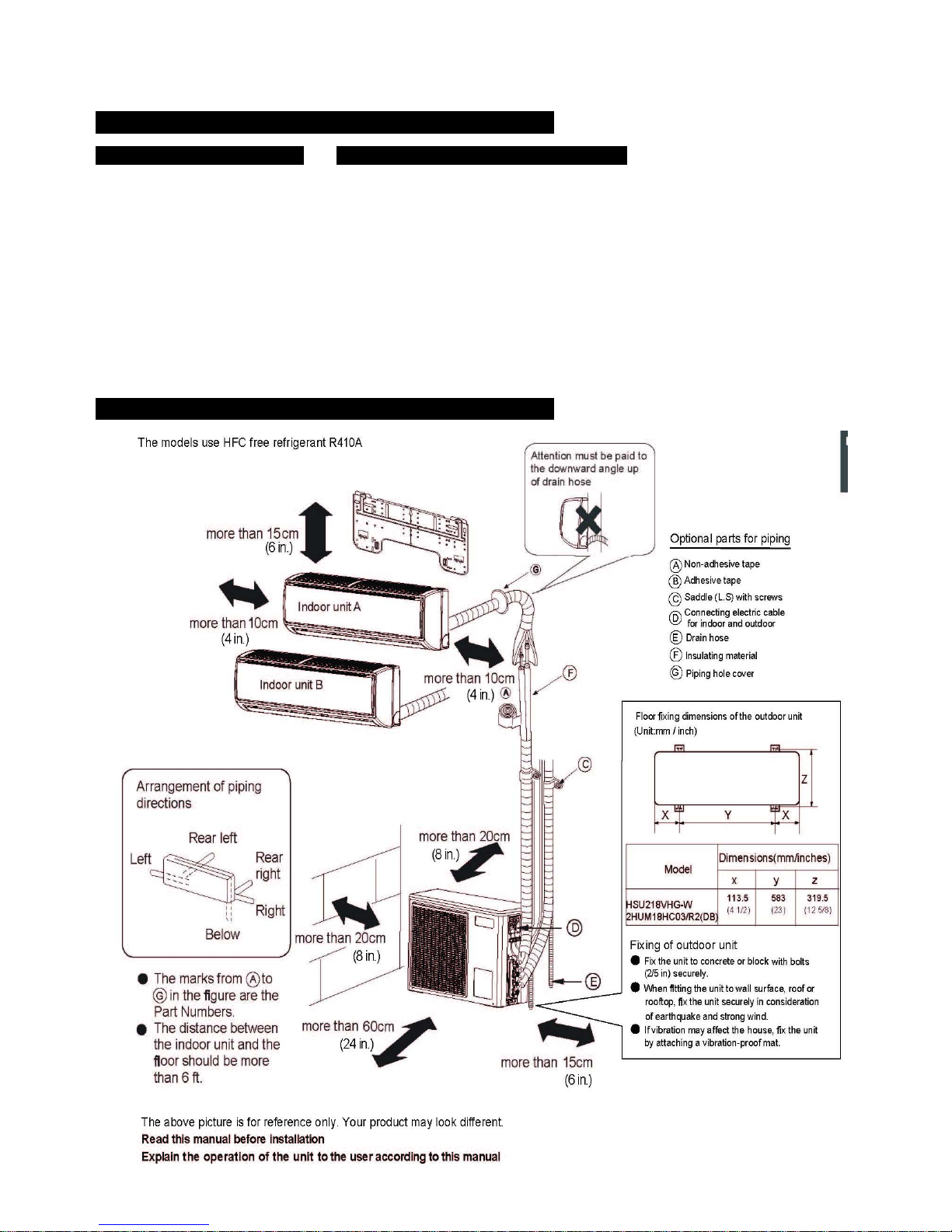
Drawing for the installation of indoor and outdoor units
Since drain flows out of the outdoor unit,do not place under the unit anything which must be kept away from moisture.
Install units,power cords and inter-unit cables at least 10ft away from televison and radio sets,This is prevent interference to
images and sounds.(Noise may be heard even if they are more than 10ft away depending on radio wave conditions.)
In coastal areas or other places with salty atmosphere of sulfate gas,corrosion may shorten the life of the air condition.
There must be sufficient space for carrying the unit into and out of the site.
Installation Manual of Duo Series
The site must be free from the possibility of flammable gas leakage in a nearby place.
Locate the unit so that the noise and discharged hot air will not annoy the neighbors.
There must be sufficient space for air passage and no obstructions aroud the air inlet and air outlet.
Gas leakage detector or
soap-and-water solution
Choose a place solid enough to bear the weight and vibration of the unit,where the operation noise will not be amplified.
Choose a location where the hot air discharged from the unit or the operation noise,will not cause a nuisance to the neighbors
of the user.
Avoid places near a bedroom and the like,so that the operation noise will cause no trouble.
Indoor unit
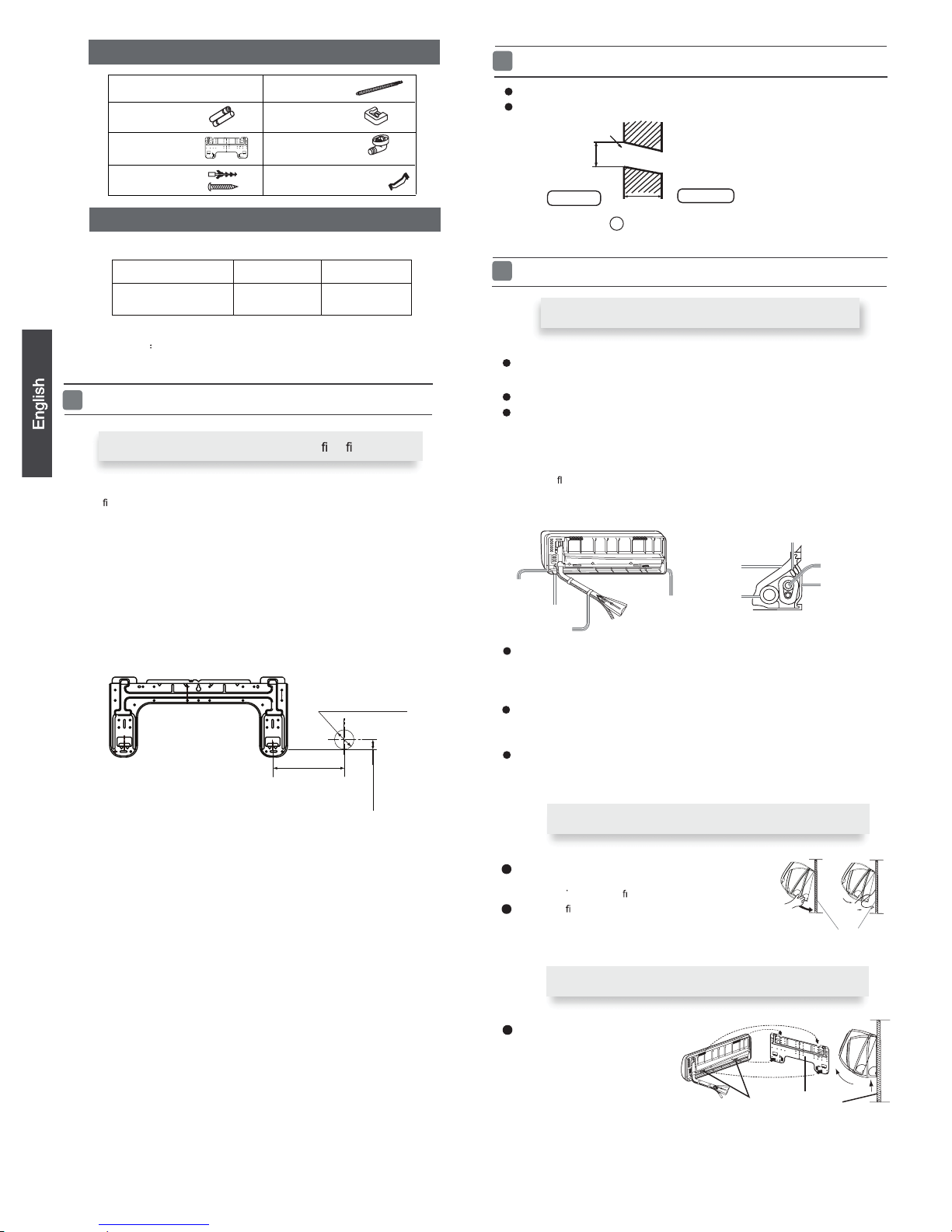
Make a hole of B mm / inches
in diameter, slightly descending
to outside the wall.
Install piping hole cover and seal it off with putty after installation
When the mounting plate is rst xed
1. Carry out, based on the wall studs or lintels,
to be
xed against the wall, then temporarily fasten the plate with one nail.
2. Assure that the mounting plate is level horizontal and vertical then fasten
the plate.
3. Find the wall hole location A using a measuring tape
1
Fitting of the Mounting Plate and
Locating of the Wall Hole
Lid for right
piping
Lid for under piping pipe
Fix with adhesive tape
Lid for left piping
Indoor/outdoor electric cable and drain hose must be bound with refrigerant
piping with adhesive.
[ Other direction piping ]
Cut away, with a nipper, the lid for piping according to the piping direction and
then bend the pipe according to theposition of wall hole. When bending, be
careful not to crush
pipes.
Make sure that the wires connecting the indoor and outdoor units are not covered
by the refrigeration piping insulation and are long enough to connect to the terminal
block on the indoor unit.
proper leveling for the plate
2
Making a Hole on the Wall and Fitting the Piping Hole Cover
Drawing of pipe
3
Installation of the Indoor Unit
[ Rear piping ]
Pull the pipes and the drain hose through, then fasten them with the adhesive tape
[ Left·Left-rear piping ]
In case of left side piping, cut away, with a nipper, the lid for left piping.
In case of left-rear piping, bend the pipes according to the piping direction to
the mark of hole for lef t-rear piping which is marked on insulation materials.
1. Insert the drain hose into the cavity of heat insulation materials of indoor unit.
2. Insert the indoor/outdoor electric cable from backside of the indoor
unit, and
pull it out on the front side, then connect them.
3. Coat the
aring seal face with refrigerant oil and connect pipes.
Cover the tubing connection with insulation materials closely, and with adhesive
tape.
Attaching the indoor unit body
Hang the indoor unit body onto the upper notches of the
mounting plate. Move the unit in all places from side to
side to verify its
secure
xing.
In order to
x the body onto the mounting plate,hold up
the body from the underside and then put it down
perpendicularly.
mounting plate
When you remove the indoor unit,please
then
lift the bottom of the unit
outward slightly and lift the unit
until it leaves the mounting plate.
agraffe
mounting plate
Removing of indoor unit body
use
your hand to raise the unit ,
Remote controller (1)
AAA dry battery (2)
Mounting plate (1)
Drain hose (1)
Ø4X25 Screw
(4)
Plastic cap (4)
Drain-elbow (1)
Cushion (4)
Pipe supporting plate (1)
Accessory parts
NOTE The thickness of the pipe must be 0.8mm(1/16”) at least.
Selection of pipe
2
Insulation
material
Drain hose
Piping
Pipe supporting
plate
Indoor/outdoor electric cab le
Indoor side
Outdoor side
ØBmm
Wall hole
Thickness of wall
(Section of wall hole)
Piping hole pipe
G
Model Liquid pipe (Ø)
Gas pipe (Ø)
6.35mm (1/4 ")
9.52mm (3/8 ")
A = 145mm
B =
Ø 60mm
30mm
HSU218VHG-W
2HUM18HC03/R2(DB)
09k/12k : B= 60mm(2 3/8 inches)
18k/24k : B=70mm(2 3/4 inches)
(5 11/16 inches)
(1 1/6
inches
)
(2 3/8 inches)
Pitch downward for drainage
 Loading...