

Haier AS18ND1HRA-WHITE, HSU18VHGL-G, 1U18FE2ERA, HSU18VHGL-W, AS24BS4HRA Service Manual
...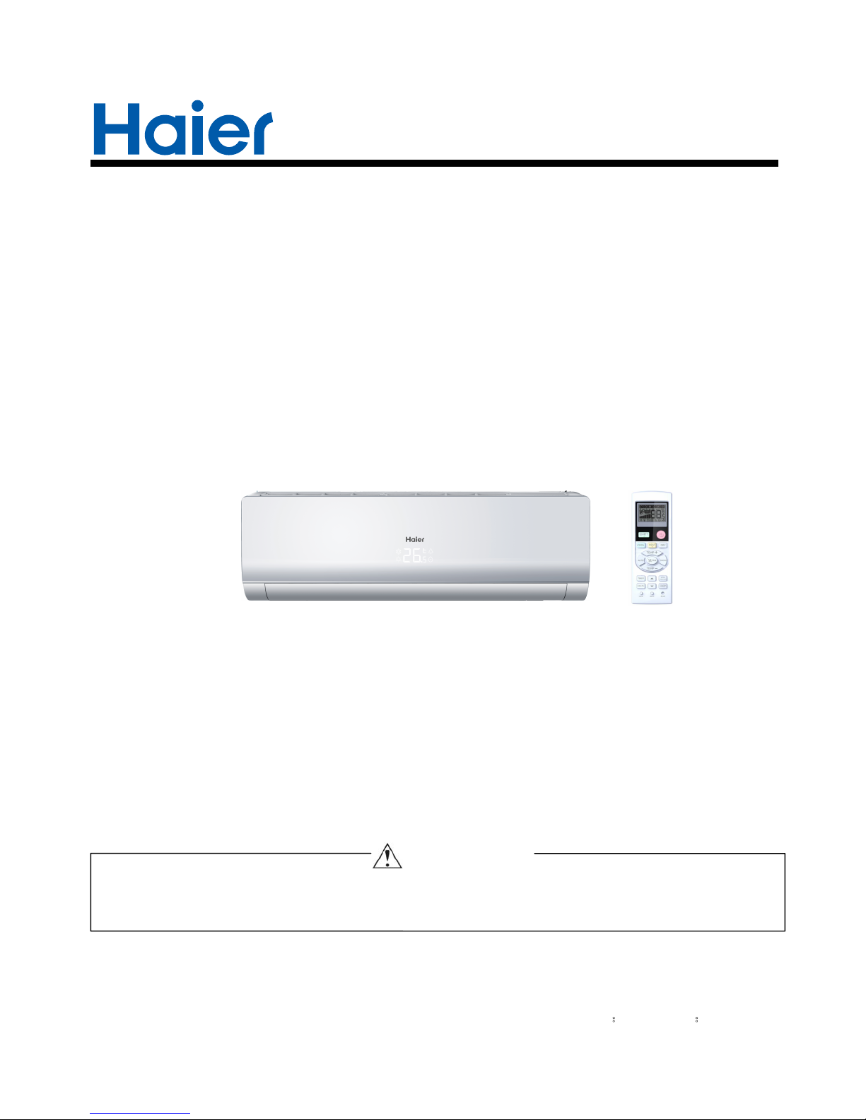
SERVICE MANAUL
Wall Mounted Type
DC Inverter FREE MATCH N-Series
AS18ND1HRA-WHITE
HSU18VHGL-G
Model No.
This service information is designed for experienced repair technicians only and is not designed for use by the general public.
It does not contain warnings or cautions to advise non-technical individuals of potential dangers in attempting to service a product.
Products powered by electricity should be serviced or repaired only by experienced professional technicians. Any attempt to service or
Repair the product or products dealt with in this service information by anyone else could result in serious injury or death
WARNING
2014 (Qingdao Haier Air Conditioner General corp. , Ltd)
All rights reserved. Unauthorized copying and distribution is a violation of law
Haier Group
Version:V1 Date:2014-05-25
Table of contents
Domestic air conditioner
Contents
1. Introduction ............................................................................................ 1
2. Features ................................................................................................ 7
3. Specifications ........................................................................................ 8
4. Sensors list............................................................................................ 9
5. Piping diagrams .....................................................................................10
6. Printed Circuit Board Connector Wiring Diagram..................................11
7. Functions and Control ...........................................................................
8. System configuration.............................................................................
9. Dimensional drawings ...........................................................................
10. Conter of gravity..................................................................................
11. Service Diagnosis ................................................................................
12. Circuit diagrams
..................................................................................
14
59
43
42
42
25
Introduction
Domestic air conditioner
1 Introduction
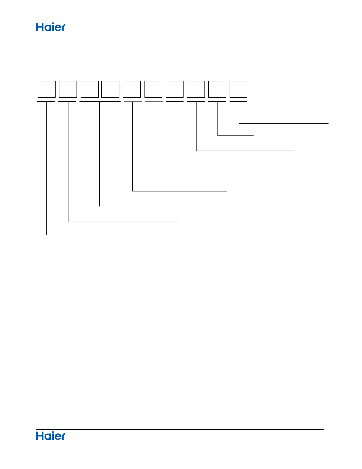
1.1 Model name explanation
A S 1 8 N D 1 H R A
Indoor unit
Type of indoor unit: S (wall-mounted)
Nominal cooling capacity (18000BTU/h)
Version number
Heat pump & R410A refrigerant
DC inverter
Apply toT1; 208~230V60HZ/1ph
1
Platform of indoor units: N (N platform)
50N Platform

Intuoduction
Domestic air conditioner
1.2 Safety Cautions
Be sure to read the following safety cautions before conducting repair work.
The caution items are classified into “Warning” and “Caution”. The “Warning” items are especially important
since they can lead to death or serious injury if they are not followed closely. The “Caution” items can also lead
to serious accidents under some conditions if they are not followed. Therefore, be sure to observe all the safety
caution items described below.
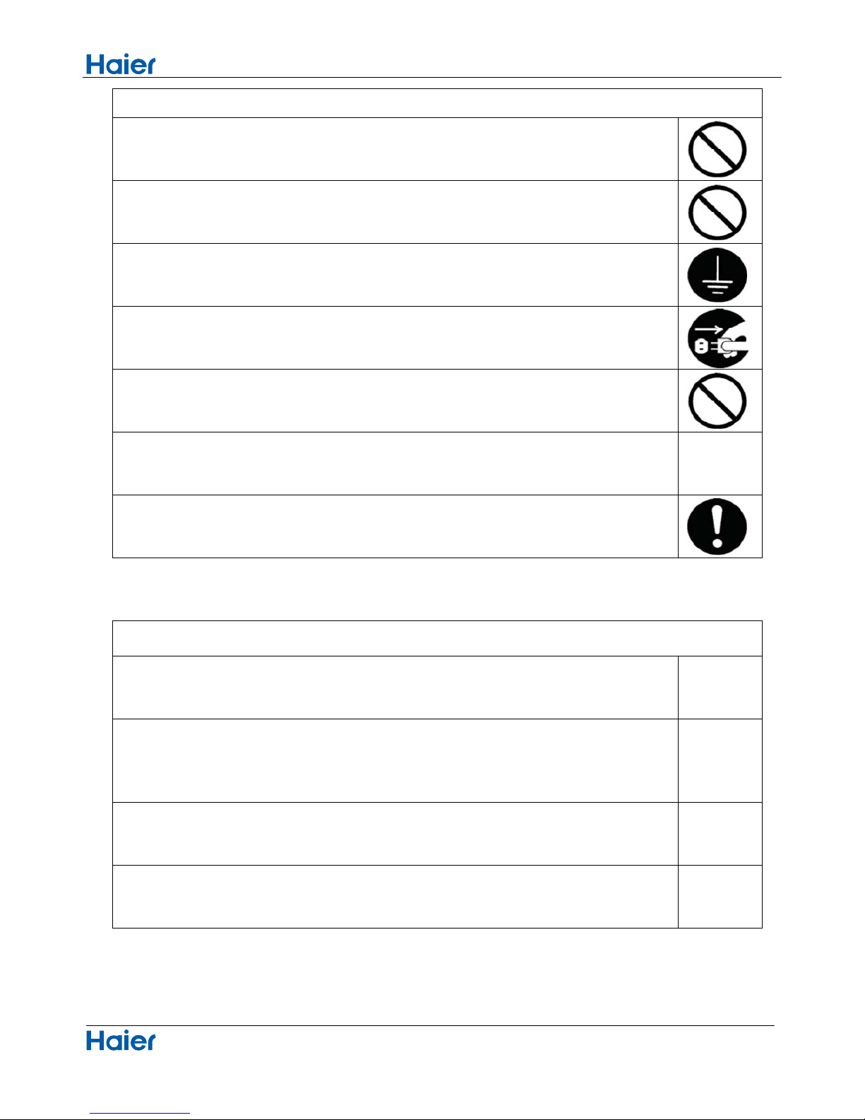
About the pictograms
△ This symbol indicates an item for which caution must be exercised.
The pictogram shows the item to which attention must be paid.
○ This symbol indicates a prohibited action.
The prohibited item or action is shown inside or near the symbol.
● This symbol indicates an action that must be taken, or an instruction.
The instruction is shown inside or near the symbol.
After the repair work is complete, be sure to conduct a test operation to ensure that the equipment operates
Normally, and explain the cautions for operating the product to the customer.
1.2.1 Caution in Repair
Warning
Be sure to disconnect the power cable plug from the plug socket before disassembling the equipment for
a repair.
Working on the equipment that is connected to a power supply can cause an electrical shook.
If it is necessary to supply power to the equipment to conduct the repair or inspecting the circuits, do not
touch any electrically charged sections of the equipment.
If the refrigerant gas discharges during the repair work, do not touch the discharging refrigerant gas .The
refrigerant gas can cause frostbite.
When disconnecting the suction or discharge pipe of the compressor at the welded section, release the
refrigerant gas completely at a well-ventilated place first.
If there is a gas remaining inside the compressor , the refrigerant gas or refrigerating machine oil
discharges when the pipe is disconnected, and it can cause injury.
If the refrigerant gas leaks during the repair work, ventilate the area. The refrigerant gas can generate
toxic gases when it contacts flames.
The step-up capacitor supplies high-voltage electricity to the electrical components of the outdoor unit.
Be sure to discharge the capacitor completely before conducting repair work . A charged capacitor can
cause an electrical shock.
Do not start or stop the air conditioner operation by plugging or unplugging the power cable plug.
Plugging or unplugging the power cable plug to operate the equipment can cause an electrical shock or
fire.
2
Intuoduction
Domestic air conditioner
Warning
Do not repair the electrical components with wet hands . Working on the equipment with wet hands can
cause an electrical shock
Do not clean the air conditioner by splashing water. Washing the unit with water can cause an electrical
shock.
Be sure to provide the grounding when repairing the equipment in a humid or wet place, to avoid
electrical
shock.
Be sure to turn off the power switch and unplug the power cable when cleaning the equipment. The
internal fan rotates at a high speed, and cause injury.
Do not tilt the unit when removing it. The water inside the unit can spill and wet the furniture and floor.
Be sure to check that the refrigerating cycle section has cooled down sufficiently before conducting
repair
work. Working on the unit when the refrigerating cycle section is hot can cause burns.
Use the welder in a well-ventilated place. Using the welder in an enclosed room can cause oxygen
deficiency.
1.2.2 Cautions Regarding Products after Repair
Warning
Be sure to use parts listed in the service parts list of the applicable model and appropriate tools to
conduct repair work. Never attempt to modify the equipment. The use of inappropriate parts or tools can
cause an electrical shock, excessive heat generation or fire.
When relocating the equipment, make sure that the new installation site has sufficient strength to
withstand the weight of the equipment.
If the installation site does not have sufficient strength and if the installation work is not conducted
securely, the equipment can fall and cause injury.
Be sure to install the product correctly by using the provided standard installation frame.
Incorrect use of the installation frame and improper installation can cause the equipment to fall, resulting
in injury.
For
integral
units only
Be sure to install the product securely in the installation frame mounted on a window frame.
If the unit is not securely mounted, it can fall and cause injury.
For
integral
units only
3
Intuoduction
Domestic air conditioner
Warning
Be sure to use an exclusive power circuit for the equipment, and follow the technical standards related to
the electrical equipment, the internal wiring regulations and the instruction manual for installation when
conducting electrical work.
Insufficient power circuit capacity and improper electrical work can cause an electrical shock or fire.
Be sure to use the specified cable to connect between the indoor and outdoor units. Make the
connections securely and route the cable properly so that there is no force pulling the cable at the
connection terminals.
Improper connections can cause excessive heat generation or fire.
When connecting the cable between the indoor and outdoor units, make sure that the terminal cover
does
not lift off or dismount because of the cable.
If the cover is not mounted properly, the terminal connection section can cause an electrical shock,
excessive heat generation or fire.
Do not damage or modify the power cable.
Damaged or modified power cable can cause an electrical shock or fire. Placing heavy items on the
power cable, and heating or pulling the power cable can damage the cable.
Do not mix air or gas other than the specified refrigerant (R-410A / R22) in the refrigerant system.
If air enters the refrigerating system, an excessively high pressure results, causing equipment damage
and injury.
If the refrigerant gas leaks, be sure to locate the leak and repair it before charging the refrigerant. After
charging refrigerant, make sure that there is no refrigerant leak.
If the leak cannot be located and the repair work must be stopped, be sure to perform pump-down and
close the service valve, to prevent the refrigerant gas from leaking into the room. The refrigerant gas
itself
is harmless, but it can generate toxic gases when it contacts flames, such as fan and other heaters,
stoves and ranges.
.
When replacing the coin battery in the remote controller, be sure to disposed of the old battery to prevent
children from swallowing it.
If a child swallows the coin battery, see a doctor immediately.
4
Intuoduction
Domestic air conditioner
Caution
Installation of a leakage breaker is necessary in some cases depending on the conditions of the
installation site, to prevent electrical shocks.
Do not install the equipment in a place where there is a possibility of combustible gas leaks.
If a combustible gas leaks and remains around the unit, it can cause a fire.
Be sure to install the packing and seal on the installation frame properly. If the packing and seal are not
installed properly, water can enter the room and wet the furniture and floor.
1.2.3 Inspection after Repair
Warning
Check to make sure that the power cable plug is not dirty or loose, then insert the plug into a power outlet
all the way.
If the plug has dust or loose connection, it can cause an electrical shock or fire.
If the power cable and lead wires have scratches or deteriorated, be sure to replace them.
Damaged cable and wires can cause an electrical shock, excessive heat generation or fire.
Warning
Do not use a joined power cable or extension cable, or share the same power outlet with other electrical
appliances since it can cause an electrical shock, excessive heat generation or fire.
5

Intuoduction
Domestic air conditioner
Caution
Check to see if the parts and wires are mounted and connected properly, and if the connections at the
soldered or crimped terminals are secure. Improper installation and connections can cause excessive
heat generation, fire or an electrical shock.
If the installation platform or frame has corroded, replace it. Corroded installation platform or frame can
cause the unit to fall, resulting in injury.
Check the grounding, and repair it if the equipment is not properly grounded. Improper grounding can
cause an electrical shock.
Be sure to measure the insulation resistance after the repair, and make sure that the resistance is 1 M
ohm or higher.
Faulty insulation can cause an electrical shock.
Be sure to check the drainage of the indoor unit after the repair.
Faulty drainage can cause the water to enter the room and wet the furniture and floor.
1.2.4 Using Icons
Icons are used to attract the attention of the reader to specific information. The meaning of each icon is described in
the table below:
1.2.5 Using Icons List
Icon Type of Information Description
Note
Note
A “note” provides information that is not indispensable, but may
nevertheless be valuable to the reader, such as tips and tricks.
Caution
Caution
A “caution” is used when there is danger that the reader, through
incorrect manipulation, may damage equipment, loose data, get
an
unexpected result or has to restart (part of) a procedure.
Warning
Warning
A “warning” is used when there is danger of personal injury.
Reference
A “reference” guides the reader to other places in this binder or in
this manual, where he/she will find additional information on a
specific topic.
6
Specifications
Domestic air conditioner
2.Features
7
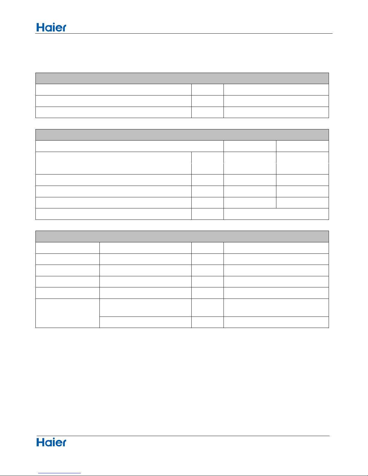
Super quiet: Lower noise operation condition
A-PAM DC inverter:With adoption of S-TYPE,S-PAM and PHASE control technology to works more
stably at low-frequency,and is more energy-saving,mor powerful at high frequency.
Long distance air supplying:
5 F° Heating: When 5 °F can still heating natural
50 °F heating maintenance:Heating Holding 50°F temperature
Confortable sleep:The setting temperature and the indoor noise can be adjusted to a more comfortable
level when you set the “sleep mode” during night sleep.
Super match:One outdoor unit can match two or more indoor unit.
DIY auto mode: Adjust the last fixed operation mode automatically.
Turbo mode: Quick cooling or heating
Auto restart: Automatic return to previous operation conditions after sudden power blackout
24 hours timer: Use the timer function to set on,or off,or from on to off,or from off to on.
Intergr
ative valve cover:The valve cover is Intergrative.
2-way piping design: The pipe can shoot out both from left or right side.
Easy clean design: The panel is easy to wash and the airflow vents can be detached easily
Double 8 display:The display is Double 8 mode.
Specifications
Domestic air conditioner
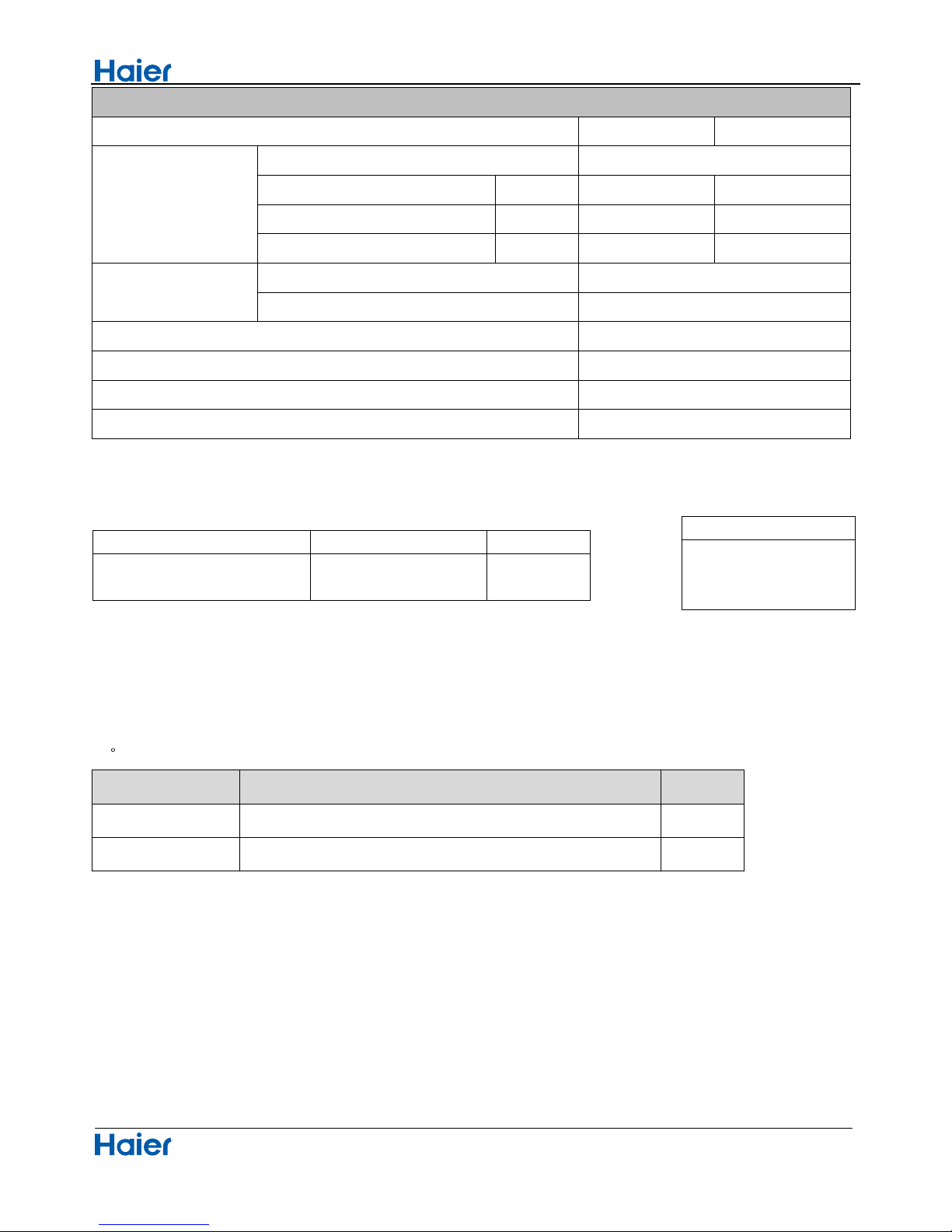
3 Specifications
NOMINAL DISTRIBUTION SYSTEM VOLTAGE
1/esahP
05zHycneuqerF
032VegatloV
NOMINAL CAPACITY and NOMINAL INPUT
cooling heating
Capacity rated
Btu/h
17000(4780-13300) 18000(5120-13990)
Power Consumption(Ra 50685222Btu)det
38/BtuBtuPOC/REE
hWKnoitpmusnocygrenelaunnA 999950 6252250
h/³inlavomeRerutsioM 70.62*10 ³
TECHNICAL SPECIFICATIONS
1.06×0.77×3.21inD*W*HsnoisnemiD
1.32×1.08×3.56inD*W*HsnoisnemiDdegakcaP
28.6lb/thgieW
35.2lb/thgiewssorG
etihW//roloC
Sound level
Sound
peessure(high/medium/low)
dB
Sound power(high) dB
8
-
57/54/51
38
/
Specifications
Domestic air conditioner
TECHNICAL SPECIFICATIONS-PARTS
cooling heating
Fan
nafwolfssorCepyT
136.5WtuptuorotoM
Air flow rate(high) in³/h 31779 31779
Speed(high/middle/low) rpm 950/850/750 900/ 800/700
Heat exchanger
Type
ML fin-φ7HI-HX tube
4.1*81*3hctif*egats*tnemgeS
hgiRlortnocnoitceridriA t,Left,Horizontal,Downward
Air filter
Removable/Washable/Mildew Proof
Temperature control
Microcomputer Control
HD01-RYledomrellortnocetomeR
Note: the data are based on the conditions shown in the table below
htgnelgnipiPgnitaehgnilooc
16.4in
4.Sensors list
type Description Qty
1erutarepmetmoorgnitcetedrofdesustIrosnesmooR
Pipe sensor Its used for detecting temperature of evaporator 1
Conversation formulae
Kcal/h= KW×860
Btu/h= KW×3414
cfm=m³/min×35.3
9
136.5
Indoor:
80.6°
F
DB/66.2°
F
W B
Outdoor: 95°
F
DB/75.2°FW B
Indoor:68°
F
D B
Ou t doo r: 44.6°
F
D B / 42.8°
F
W B
Piping diagrams
Domestic air conditioner
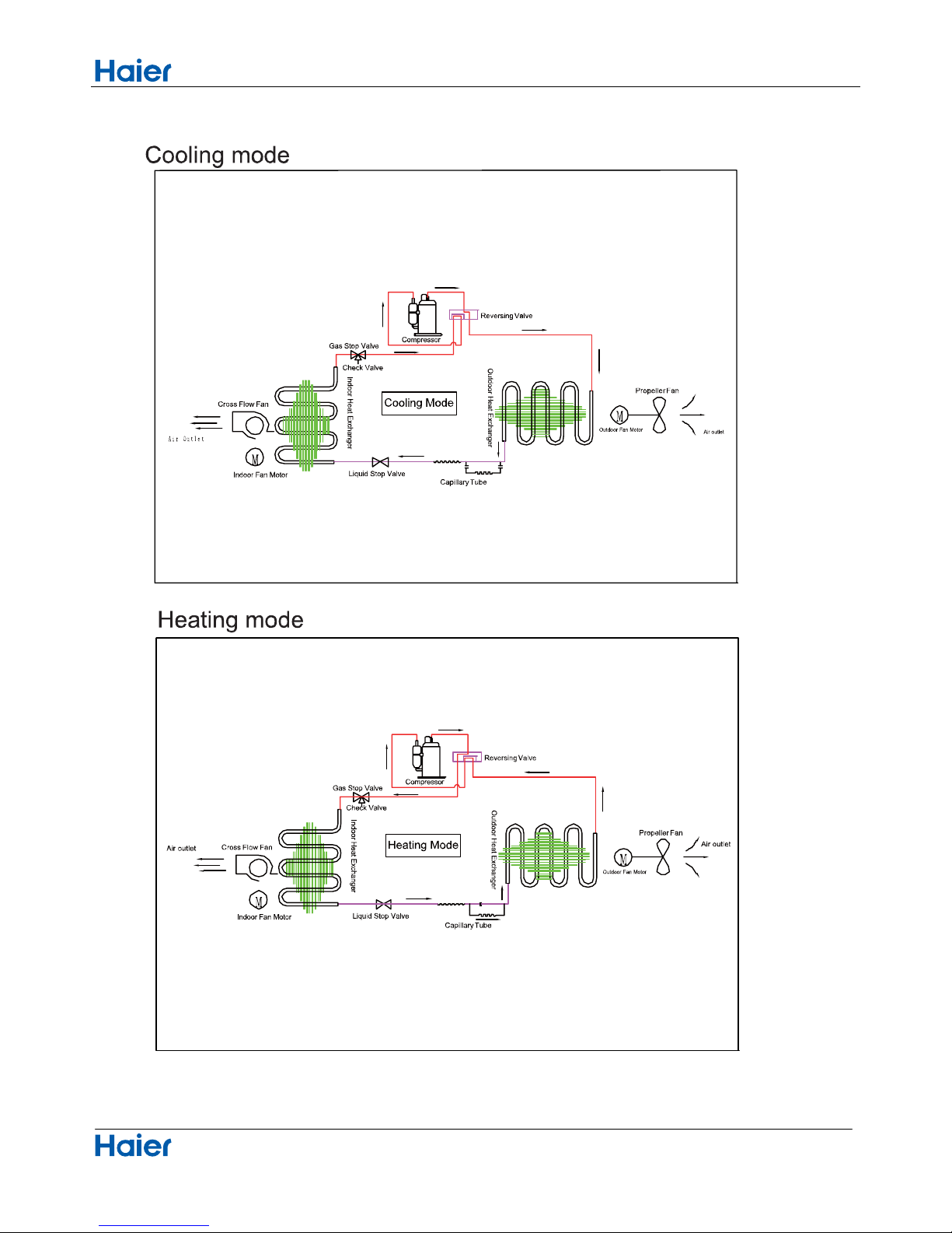
5.Pinping diagrams
10
Connector Wiring diagrams
Domestic air conditioner
6. Printed Circuit Board Connector Wiring Diagram
11
Connectors
PCB(1) (Control PCB)
daolhtiwtcennoC
rotcennocBCPseires
1 CN9
Connector for fan motor
2 CN6
Connector for heat exchanger thermistor and Room temperature thermistor
3
CN5
Connector for UP&DOWN STEP motor
4 CN21
Connector for power N wire
5 CN52
Connector for power L
6 CN27
7 CN7
8 CN23 Connector for communicate between the indoor board and the outdoor board
9 CN34
Connector for power GRN
Connector for display board
Note: Other designations
PCB(1) (Indoor Control PCB)
1) CN14 Connector for Forced operation ON / OFF switch
2) SW2 1 Select remote code A or B,2 Select room card able or disable , 3-4 Select 23,26,33,or 35
3) RV1 Varistor
4) FUSE1 Fuse 3.15A/250VAC
Connector for long-range control

Connector Wiring diagrams
Domestic air conditioner
12
PCB(1)
C23
CN21
CN7
CN14
CN6
CN52
CN34
CN9
CN5
CN27
Connector Wiring diagrams
Domestic air conditioner
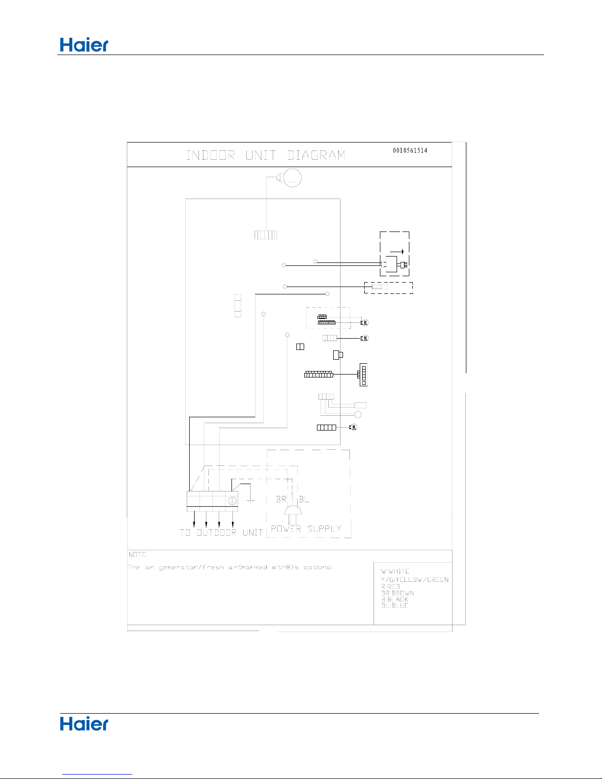
Wiring diagrams
13
up-down stepmoter
ION GENERATIOR
Y/G
C0N2
C0N3
DC FAN MOTOR
M
FUSE1
SW1
EMERGENCY SWITCH
RECEIVER
DISPLAY
CN7
T3.15A/250V AC
80
120
1
(N)
(C)
3
(L)
2
W
B
Y/G
Y/G
GND
CN14
AMBIENT TEMP SENSOR
PIPING TEMP SENSOR
CN6
CN10
Right stepmoter
left stepmoter
CN11
CN5
CN5-1 CN5-2
R
C0N1
BL
Fresh air
(L)
CN21
N
S
CN51
Room card
R
W
@
@
CN9
CN52
CN23
Functions and Control
Domestic air conditioner
7.Funcitions and Control
7.1 Main functions and control specification
7.1.1 Automatic operation
When the running mode is turned to automation after starting the system, the system will first determine
the running mode according to the current room temperature and then will run according to the determined
mode. Tr in the following selection conditions means room temperature, Ts means setting temperature, Tp
means temperature of indoor coil pipe
Tr 73.4°F Choose Cooling Mode
Tr
Choose Heating Mode
After turning to the automation mode, the running mode can be switched between cooling mode, fan
mode and heating mode according to the change of the indoor ambient temperature. But the automatic
conversion between cooling mode and heating mode must be conducted after 15 minutes.
7.1.2 Cooling operation mode
Temperature control range: 60.8°F---86°F
Temperature difference: 33.8°F/30.2°F
* Control features: When Tr
input airflow >Ts set temperature °F, the compressor will be opened, the indoor
fan will operate at the set speed and the mode signal will be sent to the outdoor system. When Tr
input
airflow
Ts set temperature °F, the compressor will be opened, the indoor fan will operate at the set speed
and the mode signal will be sent to the outdoor system. The system will keep the original status if Tr= Ts.
Airflow speed control: (temperature difference 33.8°F)
Automatic: When Tr
Ts+37.4°F, high speed.
When Ts+33.8°F
Tr<Ts+37.4°F, medium speed
When Tr<Ts+33.8°F , low speed
When the sensor is off, low speed
When the airflow speed has no delay from the high to low switching, the speed should be delayed for 3
minutes (remain at high speed for 3 minutes.) before the next switch.
Manus: When the system is operating, you can set the high, medium or low speed manually. (When the
sensor is on or off, the system will change the speed 2 seconds after receiving the signal.)
*Airgate location control: the location for the airgate can be set according to your needs.
*Defrosting function: preventing the frosting on the indoor heat exchanger (when cooling or dehumidifying).
When the compressor works continuously for 1/6 minutes (adaptable in EEPROM) and the temperature of
the indoor coils has been below zero centigrade
for 10 seconds, the compressor will be stopped and the
malfunction will be recorded in the malfunction list. The indoor system will continue to run. When the
temperature of the indoor coil is raised to 46°F, the compressor will be restarted again (the requirement of 3
minutes’ delay should be satisfied.)
* timing system on/off function.
* Dormant control function.
14
73.4°F
Functions and Control
Domestic air conditioner
7.1.3 Dehumidifying mode.
* temperature control range:
60.8---86 F
* temperature difference:
30.2/33.8°F
Control feature: send the dehumidifying signal to the outdoor system.
When Tr>Ts+35.6°F , the compressor will be turned on, the indoor fan will operate at the set speed.
When Tr is between the Ts and Ts+35.6°F , the outdoor system will operate at the high dehumidifying
frequency for 10 minutes and then at the low dehumidifying mode for six minutes. The indoor fan will
operate at low speed.
When Tr< Ts, the outsystem will be stopped, the indoor fan will be stopped for 3 minutes and then turned to
the low speed option.
All the frequency converses have a 30.2/33.8°F difference.
* Wind speed control: Automatic:
When Tr
Ts+41°F , high speed.
When Ts+37.4°F Tr< Ts+41°F , medium speed.
When Ts+35.6°F Tr< Ts+37.4°F, low speed.
When Tr<Ts+35.6°F, light speed.
If the outdoor fan stopped, the indoor fan will be paused for 3 minutes.
If the outdoor fan stopped for more than 3 minutes and the outdoor system still operates, the system will be
changed into light speed mode.
When the airflow speed has no delay from the high to low switching, the speed should be delayed for 3
minutes (remain at high speed for 3 minutes.) before the next switch.
Manual: When the sensor is off or Tr< Ts+37.4°F, the manual operation can not be made. (obligatory automatic
operation.)
*Airgate location control: the location for the airgate can be set according to your needs.
*Defrosting function: preventing the frosting on the indoor heat exchanger (when cooling or dehumidifying).
When the compressor works continuously for 1/6 minutes (adaptable in EEPROM) and the temperature of
the indoor coils has been below zero centigrade for 10 seconds, the compressor will be stopped and the
malfunction will be recorded in the malfunction list. The indoor system will continue to run. When the
temperature of the indoor coil is raised to 44.6°F, the compressor will be restarted again (the requirement of 3
minutes’ delay should be satisfied.)
* Coil protection (synchronic overheating protection) are installed for the four directions latch malfunctions
when dehumidifying.
* Timing system on/off function.
* Dormant control functio
n.
7.1.4 Heating operation mode.
*
temperature control range: 60.8---86 F
* temperature difference: 30.2/33.8°F
* control feature: the temperature compensation is automatically added and the system will send the heating
signals to the outdoor system.
If Tr
Ts, the outdoor compressor is turned on, the indoor fan will be at the cold air proof mode.
If Tr>Ts+35.6°F, the outdoor system is turned off, the indoor fan will be at the heat residue sending mode.
If Tr<Ts+35.6°F, the outdoor system will be turned on again, the indoor fan will be at the cold air proof mode.
15
<
<
Functions and Control
Domestic air conditioner
*Indoor fan control
manual control: You can choose high, medium, low and automatic speed control.
Automatic: When Tr<Ts, high speed.
When Ts
Tr Ts+35.6°F, medium speed.
When Tr> Ts+35.6°F, low speed.
When the airflow speed has no delay from the high to low switching, the speed should be delayed for 3
minutes (remain at high speed for 3 minutes.) before the next switch.
*Airgate location control: the location for the airgate can be set according to your needs.
Coldair proof operation
1. The indoor operation within 4 minutes after the start up is as the following diagram, the air speed can be
raised only after the speed has reached a certain level.
2. 4 minutes after the start up of the indoor fan, the light airflow and the low airflow will be turned to the set
speed airflow.
3. In the cold air proof operation, the fan won’t stop after the start up.
4. During the cold air proof operation, the indoor system will continuously send ‘indoor high speed’ signals to
the outdoor system.
* Resi
due heat sending. The indoor fan will send the residue heat at a low speed for 12 seconds.
If other conditions are satisfied, when the compressor stops, the indoor system will operate at a light speed.
The indoor fan will stop when the coil temperature is below the ‘heat start temp 4’.
* Defrosting. When the system receives the defrosting signal from outdoors, the indoor fan will stop and the
indoor temperature display won’t change. At the time, any indoor coil malfunctions will be neglected. When
the outdoor defrosting finishes, the coil malfunction will still be neglected until the compressor has been
started up for 30 seconds. The indoor temperature display will not change and the system operates at the
cold air proof mode.
* Automatic heating temperature compensation: when the system enters the heating mode, the temperature
compensation (4) will be added. When the status is switched off, the compensation will be erased.
7.1.5 Strength operation
The system enters the mode after receiving the ‘strength signal’.
Send strength operation signal to the outdoor system.
The mode change finishes the strength operation.
Entering ‘mute’, you can have normal operation or signal control such as timing to finish the strength
operation.
When the system is at the automatic option with the strength/ mute function, if the system enters the cooling
Heat start temp 1
Heat start temp
2
Heat start temp
3
Heat start temp
4
Set speed
Low speed
Light speed
Fan/off
Fan/off
Keep the hig
h
speed. The fa
n
doesn’t stop
16
Functions and Control
Domestic air conditioner
mode, the cooling strength/ mute function will be offered; if the system enters the heating mode, then the
heating strength/ mute function will be offered; if the system enters the airflow mode, there will be no
strength/ mute function.
7.1.6 Mute operation
The system enters the mode after receiving the ‘mute signal’.
a. Mute heating: the airflow speed is slight, the system sends the mute signal to the outdoor system.
b. mute cooling: the airflow speed is slight, the system sends the mute signal to the outdoor system.
When the compressor operates, the airflow speed is mute speed. EEPROM is adaptable.
Mute operation can not work under the dehumidifying and airflow-sending operation.
7.1.7 Air refreshing
After receiving the signal from the remote control, (HV series: the background light of the ‘health’ logo is
green. HS series: the ‘health’ indicator will be lighted). If the fan operates, the Nano-Aqua operates to realize
the ions sending function.
If the indoor fan stops, the Nano-Aqua is turned off.
When the Nano-Aqua is turned off, if the air refreshing system is turned on, the Nano-Aqua will be turned on
when the fan operates.
7.1.8 Timing
You can set 24 hours’ on/off timing accordingly. After the setting, the timing indicator will be lightened. Also,
the light will be turning off after the timing is finished. The followings are several timing methods.
1.system /on timing: The timing indicator will be lightened and the indoor system is under the waiting mode.
The light will be turned off when the timing is finished and the rest of the system will operate under a normal
condition. The timing starts since the last reception of the timing signal.
2.system /off timing: When the system is turned on, the timing indicator is lightened, the rest of the system
will operated under a normal condition. When set time comes, the indicator light will be turned off and the
system will be turned off. If you have set the dormant functions, the order of your settings will be operated
according to the timing settings.
3 .system /on and off timing: The settings will be completed according to the orders..
7.1.9 Dormant operation
The dormant timing is an eight hours unadaptable one. The timing signs are shown on the V series board.
(RC series show the dormant signal, the timing light is lighted on the 6 lights board).
2.1 Under the cooling/ dehumidifying operation, after the setting of the dormant operation, the set
temperature will be raised for 1 centigrade after 1 hour’s operation and will be raised for 1 centigrade 1 hour
later. The system will keep this status for 6 hours and then close.
2.2 Under the heating mode, after the setting of the dormant operation, the setting temperature will fall 2
centigrade after 1 hour’s operation and will fall 2 centigrade 1 hour later. 3 hours after the preceding
operations, the set temperature will be raised for 1 centigrade and the system will keep this status for 3 hours
and then close down.
2.3 During the dormant time, except the change of the system mode or a new press on the dormant setting
17

Functions and Control
Domestic air conditioner
keys, the timing of the 8 hours dormancy will take the first timing as the start time, any presses on other keys
will not affect the original timing.
2.4 Indoor fan control under the dormant operation.
If the indoor fan is at the high speed before the dormant operation setting, the speed will be turned to medium
after the setting. If the fan is at the medium speed before the dormant setting, the speed will be turned to low
after the setting. If the fan is at the low speed before the dormant setting, the speed will not change.
7.1.10 Urgent on/off input
Press the urgency button the buzzer will ring. The system will enter the automatic mode if you don’t press the
button for more than 5 seconds.
Under the system off mode, if you press the urgency key for 5 to 10 seconds, the system will start the test
operation.
Under the system off mode, if you press the urgency key for 10 to 15 seconds, the
display screen will show
the resume of the last malfunction.
If the system is under operation, the press on the urgency key will stop it.
Under the system off mode, the display screen will show automatic running sign.
Under the system off mode, the system will not receive the remote control signal if the press on the urgency
key doesn’t last for 15 seconds or if the key is loosened.
Urgency operation: If you press the urgency key for less than 5 seconds, the buzzer will ring when you press
the on/off key. The system will enter the urgency operation when the urgency key is loosened. The urgency
operation is fully automatic.
Test operation.
The inlet temperature sensor doesn’t work, the indoor fan and the indoor air direction board motor works
synchronically. High speed airflow, cooling, outdoor system on, etc, will send the ambient temperature 30
centigrade and coil temp
erature 16 centigrade information to the outdoor system.
Test operation
The defrost protection of the evaporator doesn’t work.
The temperature control doesn’t work.
The test operation will be finished in 30 minutes.
The test operation can be stopped by the relative commands from the remote control.
7.1.11 Low load protection control
In order to prevent the frosting of the indoor heat interaction device, the outdoor system will be stopped if the
indoor heat interaction temperature is below zero centigrade for 5 minutes, but the fan will continue to
operate. The outdoor system will be started again when the heat interaction temperature is above 7
centigrade and the system has been stopped for 3 minutes. The malfunction will be stored in the malfunction
resume and will not be revealed.
7.1.12 High load protection control
The outdoor system will be stopped if the coil temperature is above 149°F for 2 minutes. The indoor fan will be
controlled by the thermostat. The outdoor system can be restarted when the coil temperature is below 107.6°F
and the system has been stopped for 3 minutes. The malfunction will be stored in the malfunction resume
18

Functions and Control
Domestic air conditioner
and will not be revealed.
7.1.13 Abnormal operation of indoor system
When the outdoor system operates, if the indoor system operation differs from the outdoor system, the
abnormal operation malfunction will be reported. 10s after the report, the indoor system will be closed.
Outdoor system mode Indoor system mode conflicts
cooling heating yes
cooling cooling no
cooling airflow no
heating heating no
heating airflow yes
heating cooling yes
7.1.14 Malfunction list resume.
Nothing is presented if there is no code list.
The malfunction display will automatically finish in 10 seconds.
The remote control only receives the signals for stop. According to the signals, the malfunction resume
presentation finishes.
The resume restores after the power supply restores.
7.1.15 Abnormality confirmation approaches
1. indoor temperature sensor abnormality:
Under the operation, the normal temperature ranges from 248°F to -22°F. When the temperature
goes beyond this range, the
abnormality can be confirmed. If the temperature goes back into the range, the
system will automatically resume.
2 .indoor heat interaction sensor abnormality:
Under the operation, the normal temperature ranges from 248°F to -22°F. When the temperature
goes beyond this range, the abnormality can be confirmed. If the temperature goes back into the range, the
system will automatically resume.
3 .indoor malfunction:
Out door malfunction: When the indoor system receives the outdoor malfunction codes, it will store the code
into E2 for the malfunction list resume. The indoor system will continue to operate according to the original
status, the malfunction code will not be revealed or processed.
4. transmission abnormality:
If the indoor system can’t receive the outdoor system for 8 minutes, the communication abnormality can be
confirmed and reported and the outdoor system will be stopped.
7.1.16 Single indoor system operation
* Enter condition: First, set the high speed airflow and 86°F set temperature, then press the dormant
keys for 6
times within 7 seconds, the system will feedback with 6 rings.
* After the system enters the separate indoor system operation mode, the indoor system will operate
19

Functions and Control
Domestic air conditioner
according to the set mode and neglect the communication signals of the outdoor system. However, it has to
send signals to the outdoor system.
* Quitting condition: This mode can be quitted after receiving the quitting signal from the remote control or
urgency system. The indoor system thus can quit the single operation mode.
7.1.17 Power cut compensation
* Entering condition: Press dormant button 10 times within 7 second, the buzzer will ring 4 times and the
present system status will be stored into the EEPROM of the indoor system.
* After entering the power cut compensation mode, the processing of the indoor system should be as the
followings:
Remote control urgency signal: operate according to the remote control and the urgent conditions, the
present status will be stored into the EEPROM of the indoor system.
* Quitting conditions: Press dormant button 10 times within 7 seconds and the buzzer will ring twice.
7.1.18 Fixed frequency operation
1. Fixed cooling: a. under G code condition: high speed cooling, set 60.8°F , press temperature ‘-‘ key and the
set key at the same time. The system will enter the fixed frequency operation after the buzzer rings twice.
b. The proceeding programs are as the follows:
Entering the fixed frequency operation, you can set the fixed strength location 1 and send the cooling signal
to the outdoor system. Meanwhile, you can fix the indoor system at high speed mode, the location of the
airflow direction board can be switched to the maximal position.
c. Quitting condition: The fixed frequency cooling can be quitted after receiving the remote signal, and the
system will enter the remote setting status.
2. Fixed heating: a. under G code condition: high speed heating, set 86°F, press temperature ‘+‘ key and the
set key at the same time. The system will enter the fixed frequency operation after the buzzer rings twice.
b. The proceeding p
rograms are as the follows:
Entering the fixed frequency operation, you can set the fixed strength location 1 and send the heating signal
to the outdoor system. Meanwhile, you can fix the indoor system at high speed mode, the location of the
airflow direction board can be switched to the maximal position.
c. Quitting condition: The fixed frequency heating can be quitted after receiving the remote signal, and the
system will enter the remote setting status.
7.1.19 Test program
First, connect the test program terminal on the mainboard. Then connect the system to the power circuit. The
test program will operate as follows.
HV series display: The buzzer rings for one time—the signal will be sent to outdoor system for 0.5 second—
the violet is sent for 0.5-- the background light turns to white—the back ground light turns to white—the
background light turns to white—the background li
ght is fully lighted for 0.5 second—LED screen lights for
0.5 second— the step-in motor fully output for 0.5 second—then the motor doesn’t output for 0.5
second—the motor fully output again for 0.5 second. The test program finishes.
20
Functions and Control
Domestic air conditioner
7.1.20 Time cutting function:
Connect the test program terminal on the mainboard after connecting the system to the power circuit. The
CPU of the main control will be 60 times faster.
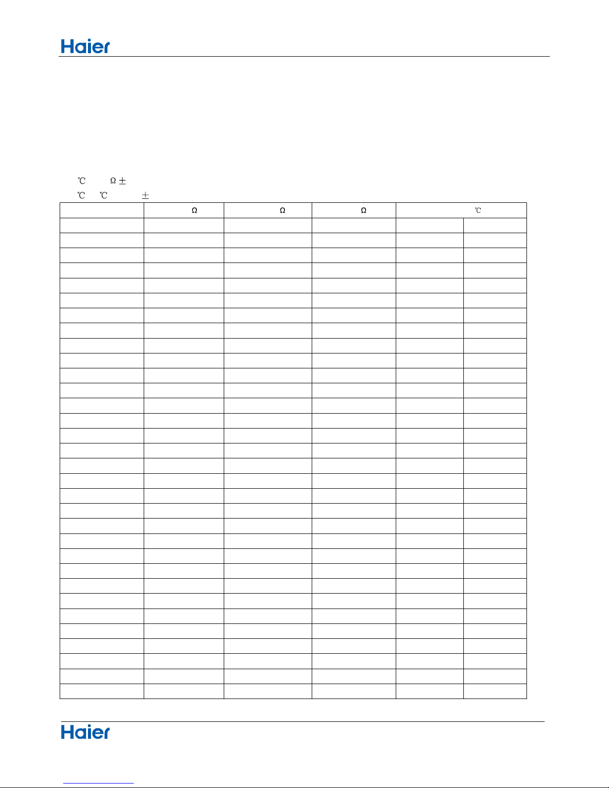
7.2 Value of thermistor
Room sensor and Pipe Sensor
R25 =10K 3%
B25
/50 =3700K 3%
Temp.(( °F ))
Max.(K
) Normal(K ) Min.(K )
Tolerance(
)
-22 165.2170 147.9497 132.3678 28.51 35.15
-20.2 155.5754 139.5600 125.0806 28.53 35.13
-18.4 146.5609 131.7022 118.2434 28.56 35.11
-16.6 138.1285 124.3392 111.8256 28.60 35.08
-14.8 130.2371 117.4366 105.7989 28.63 35.06
-13 122.8484 110.9627 100.1367 28.67 35.04
-11.2 115.9272 104.8882 94.8149 28.71 35.01
-9.4 109.4410 99.1858 89.8106 28.74 34.99
-7.6 103.3598 93.8305 85.1031 28.76 34.95
-5.8 97.6556 88.7989 80.6728 28.80 34.93
-4 92.3028 84.0695 76.5017 28.83 34.92
-2.2 87.2775 79.6222 72.5729 28.87 34.88
-0.4 82.5577 75.4384 68.8710 28.90 34.86
-1.4 78.1230 71.5010 65.3815 28.94 34.83
-3.2 73.9543 67.7939 62.0907 28.98 34.79
-5 70.0342 64.3023 58.9863 29.01 34.77
-6.8 66.3463 61.0123 56.0565 29.05 34.74
-8.6 62.8755 57.9110 53.2905 29.08 34.72
-10.4 59.6076 54.9866 50.6781 29.12 34.68
-12.2 56.5296 52.2278 48.2099 29.16 34.65
-14 53.6294 49.6244 45.8771 29.19 34.63
15.8 50.8956 47.1666 43.6714 29.23 34.59
17.6 48.3178 44.8454 41.5851 29.28 34.56
19.4 45.8860 42.6525 39.6112 29.32 34.52
21.2 43.5912 40.5800 37.7429 29.35 34.50
23 41.4249 38.6207 35.9739 29.39 34.47
24.8 39.3792 36.7676 34.2983 29.43 34.43
26.6 37.4465 35.0144 32.7108 29.46 34.39
28.4 35.6202 33.3552 31.2062 29.52 34.36
30.2 33.8936 31.7844 29.7796 29.55 34.32
32 32.2608 30.2968 28.4267 29.59 34.30
33.8 30.7162 28.8875 27.1431 29.62 34.27
21

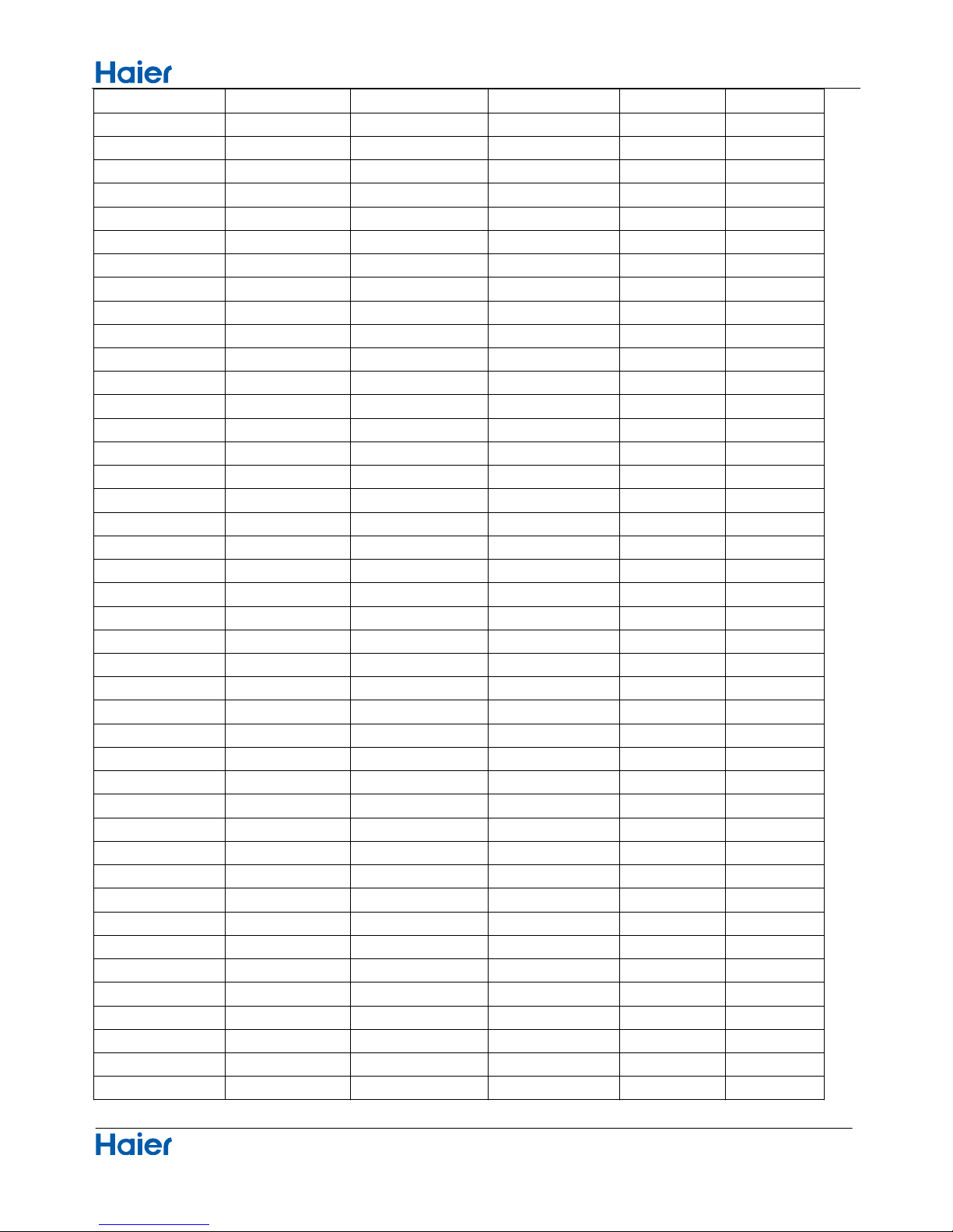
Functions and Control
Domestic air conditioner
35.6 29.2545 27.5519 25.9250 29.68 34.23
37.4 27.8708 26.2858 24.7686 29.71 34.20
39.2 26.5605 25.0851 23.6704 29.75 34.16
41 25.3193 23.9462 22.6273 29.79 34.12
42.8 24.1432 22.8656 21.6361 29.84 34.09
44.6 23.0284 21.8398 20.6939 29.88 34.05
46.4 21.9714 20.8659 19.7982 29.93 34.02
48.2 20.9688 19.9409 18.9463 29.97 33.96
50 20.0176 19.0621 18.1358 30.00 33.93
51.8 19.1149 18.2270 17.3646 30.06 33.89
53.6 18.2580 17.4331 16.6305 30.09 33.85
55.4 17.4442 16.6782 15.9315 30.15 33.82
57.2 16.6711 15.9601 15.2657 30.18 33.78
59 15.9366 15.2770 14.6315 30.24 33.73
60.8 15.2385 14.6268 14.0271 30.27 33.69
62.6 14.5748 14.0079 13.4510 30.33 33.66
64.4 13.9436 13.4185 12.9017 30.36 33.62
66.2 13.3431 12.8572 12.3778 30.42 33.57
68 12.7718 12.3223 11.8780 30.45 33.53
69.8 12.2280 11.8126 11.4011 30.51 33.49
71.6 11.7102 11.3267 10.9459 30.54 33.44
73.4 11.2172 10.8634 10.5114 30.60 33.40
75.2 10.7475 10.4216 10.0964 30.65 33.35
77 10.3000 10.0000 9.7000 30.65 33.35
78.8 9.8975 9.5974 9.2980 30.63 33.37
80.6 9.5129 9.2132 8.9148 30.56 33.34
82.4 9.1454 8.8465 8.5496 30.49 33.49
84.2 8.7942 8.4964 8.2013 30.43 33.55
86 8.4583 8.1621 7.8691 30.36 33.62
87.8 8.1371 7.8428 7.5522 30.29 33.67
89.6 7.8299 7.5377 7.2498 30.24 33.75
91.4 7.5359 7.2461 6.9611 30.16 33.80
93.2 7.2546 6.9673 6.6854 30.09 33.87
95 6.9852 6.7008 6.4222 30.02 33.93
96.8 6.7273 6.4459 6.1707 29.97 34.00
98.6 6.4803 6.2021 5.9304 29.89 34.05
100.4 6.2437 5.9687 5.7007 29.82 34.12
102.2 6.0170 5.7454 5.4812 29.75 34.20
104 5.7997 5.5316 5.2712 29.68 34.25
105.8 5.5914 5.3269 5.0704 29.61 34.32
107.6 5.3916 5.1308 4.8783 29.53 34.39
109.4 5.2001 4.9430 4.6944 29.46 34.45
111.2 5.0163 4.7630 4.5185 29.39 34.52
22
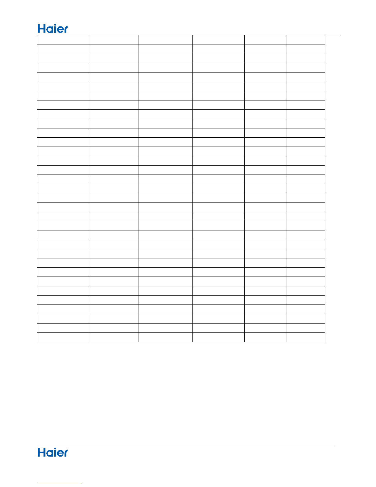
Functions and Control
Domestic air conditioner
113 4.8400 4.5905 4.3500 29.32 34.59
114.8 4.6708 4.4252 4.1887 29.25 34.65
116.6 4.5083 4.2666 4.0342 29.17 34.72
118.4 4.3524 4.1145 3.8862 29.10 34.79
120.2 4.2026 3.9686 3.7443 29.03 34.86
122 4.0588 3.8287 3.6084 28.94 34.92
123.8 3.9206 3.6943 3.4780 28.87 34.99
125.6 3.7878 3.5654 3.3531 28.80 35.06
127.4 3.6601 3.4416 3.2332 28.72 35.13
129.2 3.5374 3.3227 3.1183 28.63 35.20
131 3.4195 3.2085 3.0079 28.56 35.28
132.8 3.3060 3.0989 2.9021 28.49 35.33
134.6 3.1969 2.9935 2.8005 28.40 35.40
136.4 3.0919 2.8922 2.7029 28.33 35.47
138.2 2.9909 2.7948 2.6092 28.26 35.55
140 2.8936 2.7012 2.5193 28.17 35.62
141.8 2.8000 2.6112 2.4328 28.09 35.69
143.6 2.7099 2.5246 2.3498 28.00 35.76
145.4 2.6232 2.4413 2.2700 27.93 35.83
147.2 2.5396 2.3611 2.1932 27.84 35.91
149 2.4591 2.2840 2.1195 27.75 35.98
150.8 2.3815 2.2098 2.0486 27.68 36.05
152.6 2.3068 2.1383 1.9803 27.59 36.12
154.4 2.2347 2.0695 1.9147 27.52 36.21
156.2 2.1652 2.0032 1.8516 27.43 36.28
158 2.0983 1.9393 1.7908 27.34 36.36
159.8 2.0337 1.8778 1.7324 27.27 36.43
161.6 1.9714 1.8186 1.6761 27.18 36.50
163.4 1.9113 1.7614 1.6219 27.09 36.57
165.2 1.8533 1.7064 1.5697 27.00 36.64
167 1.7974 1.6533 1.5194 26.91 36.73
168.8 1.7434 1.6021 1.4710 26.82 36.81
170.6 1.6913 1.5528 1.4243 26.74 36.88
172.4 1.6409 1.5051 1.3794 26.65 36.95
174.2 1.5923 1.4592 1.3360 26.56 37.04
176 1.5454 1.4149 1.2942 26.47 37.11
177.8 1.5000 1.3721 1.2540 26.38 37.18
179.6 1.4562 1.3308 1.2151 26.29 37.27
181.4 1.4139 1.2910 1.1776 26.20 37.35
183.2 1.3730 1.2525 1.1415 26.11 37.42
185 1.3335 1.2153 1.1066 26.02 37.51
186.8 1.2953 1.1794 1.0730 25.92 37.58
188.6 1.2583 1.1448 1.0405 25.83 37.67
23
Functions and Control
Domestic air conditioner
190.4 1.2226 1.1113 1.0092 25.74 37.74
192.2 1.1880 1.0789 0.9789 25.65 37.83
194 1.1546 1.0476 0.9497 25.56 37.90
195.8 1.1223 1.0174 0.9215 25.45 37.99
197.6 1.0910 0.9882 0.8942 25.36 38.07
199.4 1.0607 0.9599 0.8679 25.27 38.16
201.2 1.0314 0.9326 0.8424 25.16 38.23
203 1.0030 0.9061 0.8179 25.07 38.32
204.8 0.9756 0.8806 0.7941 24.98 38.39
206.6 0.9490 0.8558 0.7711 24.87 38.48
208.4 0.9232 0.8319 0.7489 24.78 38.55
210.2 0.8983 0.8088 0.7275 24.67 38.64
212 0.8741 0.7863 0.7067 24.58 38.73
213.8 0.8507 0.7646 0.6867 24.48 38.80
215.6 0.8281 0.7436 0.6672 24.39 38.89
217.4 0.8061 0.7233 0.6484 24.28 38.98
219.2 0.7848 0.7036 0.6303 24.19 39.06
221 0.7641 0.6845 0.6127 24.08 39.15
222.8 0.7441 0.6661 0.5957 23.97 39.24
224.6 0.7247 0.6482 0.5792 23.88 39.33
226.4 0.7059 0.6308 0.5632 23.77 39.42
228.2 0.6877 0.6140 0.5478 23.67 39.49
230 0.6700 0.5977 0.5328 23.56 39.58
231.8 0.6528 0.5820 0.5183 23.47 39.67
233.6 0.6361 0.5667 0.5043 23.36 39.76
235.4 0.6200 0.5518 0.4907 23.25 39.85
237.2 0.6043 0.5374 0.4775 23.14 39.94
239 0.5891 0.5235 0.4648 23.04 40.01
240.8 0.5743 0.5100 0.4524 22.93 40.10
242.6 0.5600 0.4968 0.4404 22.82 40.19
244.4 0.5460 0.4841 0.4288 22.71 40.28
246.2 0.5325 0.4717 0.4175 22.60 40.37
248 0.5194 0.4597 0.4066 22.50 40.46
24
System configuration
Domestic air conditioner
8 System configuration
8.1System configuration
After the installation and test operation of the room air conditioner have been completed, it should be
operated and handled as described below. Every user would like to know the correct method of operation
of the room air conditioner, to check if it is capable of cooling(or heating) well, and to know a clever method
of using it. In order to meet this expectation of the users, giving sufficient explanations taking enough time
can be said to reduce about 80% of the requests for servicing. However good the installation work is and
however good the functions are, the customer may blame either the room air conditioner or its installation
work because of improper handling. The installation work and handing over of the unit can only be
considered to have been completed when its handling has been explained to the user without using
technical terms but giving full knowledge of the equipment.
8.2 Instruction
25
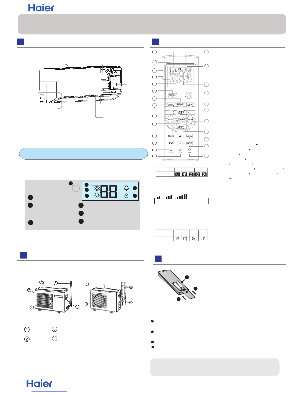
Display board
Signal receiver hole
COOL display
HEALTH display
4
2
3
1
5
DRY display
6
Ambient temp.display
When receiving the remote
control signal, display the set
temperature.
2
3
5
6
4
HEAT display
1
Outlet
Horizontal flap
Display board
(adjust up and down air flow
Don't adjust it manually)
(adjust left and
ow)
Vertical blade
Emergency
Switch
right air fl
Inlet
Air Purifying Filter
(inside)
Inlet grille
Anion generator
(inside)
(inside)
Actual inlet grille may vary from the one shown in the
manual according to the product purchased
The unit pictured above is for reference only.
Your product may appear different.
4
Outdoor Unit
4
Inserting the Battery
Parts and Functions
Indoor Unit
OUTLET
INLET
CONNECTING PIPING AND ELECTRICAL WIRING
DRAIN HOSE
Remote Control
Hint:
Remove the batteries if the unit won't be in use for a long period. If
there is any display after taking-out the batteries, just press reset key.
1. Mode display
2. Signal sending display
4. FAN SPEED display
5. LOCK display
6. TIMER OFF display
TIMER ON display
LO MED HI
7.TEMP display
16. LOCK button
Used to lock buttons and LCD display.
25. RESET button
If the remote is not functioning properly,
use a pen point or similar object to
depress the button to reset the remote
22. HOUR button
Operation mode
NAFOTUA COOL DRY
Remote controller
HEAT
1
2
3
4
5
9
10
11
12
13
14
15
16
17
22
23
24
25
19
20
21
8
18
7
6
Control the lightening and extinguishing
of the indoor LED display board.
3. SWING display
8
.
9. QUIET button
10. HEAT button
11. COOL button
12. AUTO button
13. FAN button
14. TIMER button
15. HEALTH button
17. LIGHT button
18. POWER ON/OFF button
19. DRY button
20. TEMP button
21. SWING button
23. EXTRA FUNCTION button
24.CANCEL/CONFIRM button
AUTO
Function: Setting and cancel to the
timer and other additional functions.
Display
circulated
Operation mode
Remote controller
QUITE
POWER
SLEEP
HEALTH
Additional functions display
Healthy function is not available for some units.
1
2
3
4
Remove the battery cover;
Insert the batteries as illustrated.
2 AAA batteries.
+ -.
Then put on the cover again.
Note:
1
2
3
Be sure battery polarity is
correct
The distance from the remote to the receiver should be less than
23 feet (7 meters) with no obstructions.
Fluorescent lights or cordless telephones will reduce the range
of the remote.
If the display is dim the remote batteries may need to be replaced.
Remote malfunctions can sometimes be corrected by removing
the batteries for a few minutes and then replacing them.
Function:Fan Mode— Healthy
airflow upwarder — Healthy airflow
downwarder— Reset the healthy
airflow position — Right & left airflow
setting— A-B yard— 50
°F
low
temperature heating— Sleep Mode—
Electrical Heating— Refresh Air—
Power — Fahrenheit/Celsius mode
shift on unit and remote
Remark:A-B yard, Right & left airflow
setting, 50
°F low temperature heating,
Electrical Heating, Refresh Air functions
are not available for this mini split series.
Installation
Domestic air conditioner
26

Operation
Air Flow Direction Adjustment
Press FAN button. For each press, fan speed
follows:
Remote controller:
Press
button
Every time the button is pressed, temp.setting
increase 1
o
C / 2 F, if kept depressed, it will
increase rapidly
Every time the button is pressed, temp.setting
decrease 1
o
C / 2 F, if kept depressed, it will
decrease rapidly
Select a desired temperature.
4.Fan speed selection
3.Select temp.setting
The air conditioner will be running at the speed shown
in the display.
When FAN is set to AUTO, the air conditioner
automatically adjusts the fan speed according to room
temperature.
1. Unit start
Press ON/OFF on the remote controller, unit starts.
/
Basic Operation
at air outlet if all vertical louvers are
right.
Note:
changes as
COOL/DRY:
HEAT:
Initial state
o
Beep-Beep
stereoscopic air flow
Display
circulated
LOW
MED HI
AUTO
Remote controller
1.Status display of air flow
When restarting the unit after it has been turned off,
the unit will keep the swing position before it stops
working.
2.Left and right air flow adjustment
(manual)
Cautions:
When adjusting the louver by hand,turn off the unit.
When humidity is high,condensate water might occur
adjusted to left or
It is advisable not to keep horizontal louver at
downward position for a long time in COOL or DRY
mode ,otherwise, condensate water might occur.
Emergency Operation and Test Operation
Operation
Mode
Remote
Controller
Note
In DRY mode , when room temperature is 2 C/4 F degrees
o
less than the temperature set point, the unit will run
intermittently at LOW speed regardless of FAN setting.
Under the mode of auto operation, air conditioner will
automatically select Cool or Heat operation according to
room temperature. When FAN is set to AUTO the air
conditioner automatically adjusts the fan speed according
to room temperature.
In FAN operation mode , the unit will not operate in COOL or
HEAT mode but only in
FAN mode, AUTO is not available in
FAN mode. And temp. setting is disabled. In FAN mode,
sleep operation is not available.
Emergency Operation:
Use this operation only when the remote controller is defective
or lost, and with function of emergency running, air conditoner
can run automatically in few seconds.
When power switch is turned on for the first time and
emergency operation starts, the unit will run automatically in
the following modes:
Room
temperature
Designated
temperature
Timer
mode
Fan
speed
Operation
mode
Above 23℃/73℉ 26℃ / 79℉
Below 23℃/73℉ 23℃ / 73℉
No
AUTO
AUTO
COOL
HEAT
No
During emergency operation it is impossible to change the
settings of temp. and fan speed,It is also not possible to
operate in Timer or Dry mode.
the room
temperature is below 16
℃ / 60℉
,
Test Operation:
Use this switch in the test operation when
do not use it in the normal operation.
Test ope ration switch is the same as emergency switch.
Under this operation mode,the fan motor of indoor
unit will run in high speed.
1
4
3
3
2. Select operation mode
2
COOL button:Cooling mode
HEAT button: Heating mode
DRY button: Dehumidify mode
Beep
DRY
COOL
AUTO
HEAT
FAN
In HEAT mode, warm air will blow out after a short
period of the time due to cold-draft prevention function.
When FAN is set to AUTO, the air conditioner automatically
adjusts the fan speed according to room temperature.
When the emergency operation switch is pressed, the unit
beeps once, which starts the operation.
from the switch: the cooling operation
Continue to press the test operation
switch for more than 5 seconds.After
you hear two beeps, release your finger
starts with the air flow speed "HI".
Move the vertical louver by a knob on air
to adjust left and right direction to achieve
stereoscopic air flow as the figure below.
conditioner
o
o
Installation
Domestic air conditioner
27
Operation
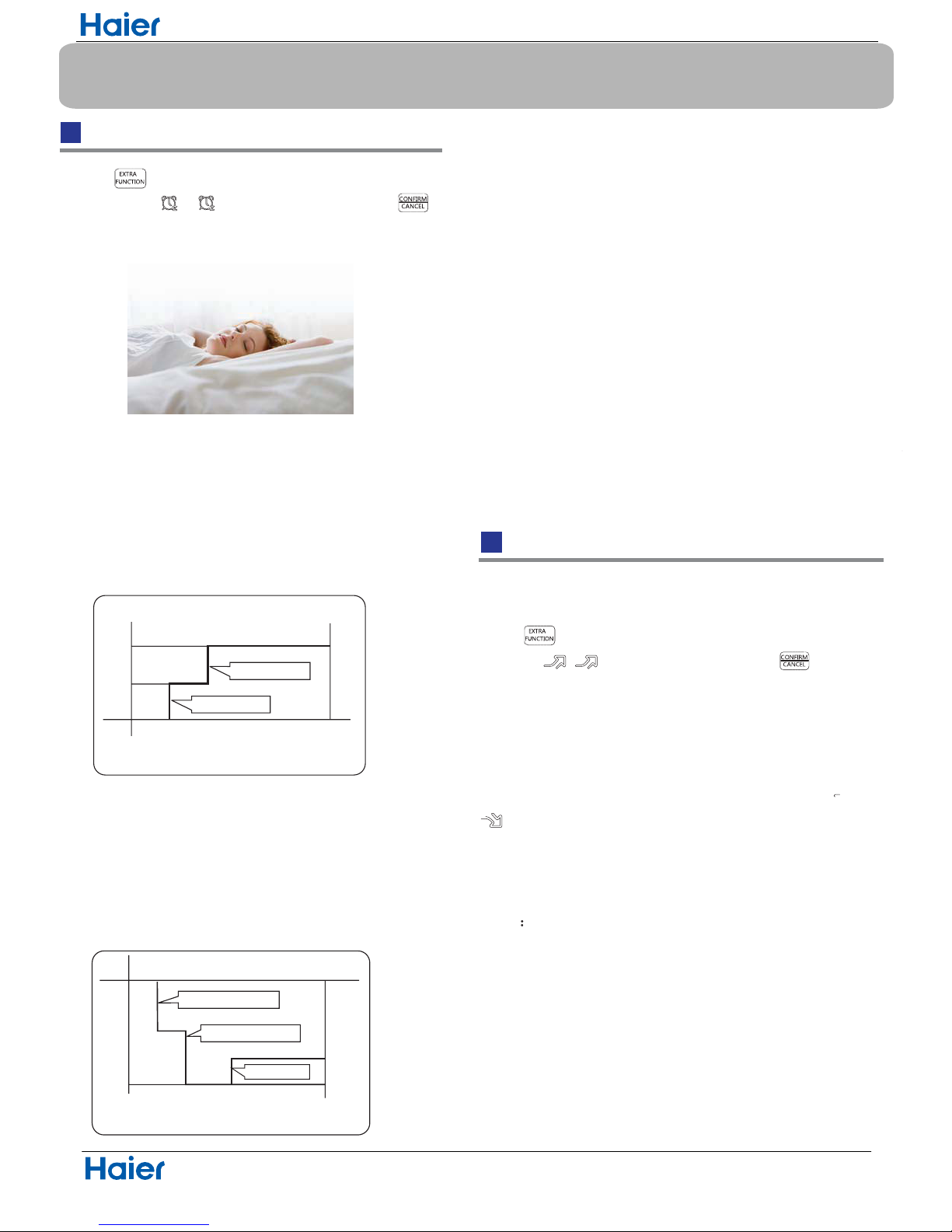
Sleep Operation
5.Fan Speed in Sleep Mode
When the unit is set to sleep mode, the fan speed
will be set to low speed and it cannot be changed.
Operation Mode
1. In COOL,DRY mode
SLEEP operation starts SLEEP operation stops
SLEEP
operation starts
SLEEP
operation stops
Approx.6hrs
1 hr
1 hr
1 hr
3 hrs
3 hrs
Rises 1OC/ 2 F
Rises 1
O
C/ 2 F
Rises 1OC/ 2 F
Temp.setting
Temp.setting
Unit stop
Unit stop
In COOL, DRY mode
In HEAT mode
Decreases 2OC/ 4 F
Decreases 2
O
C/ 4 F
1 hr
2.
3.
In HEAT mode
In AUTO mode
4. In FAN mode
It has no SLEEP function.
Note
When TIMER function is set, the sleep function can’t be
set up .After the sleep function is set up, if user set up
TIMER function, the sleep function will be cancelled; the
machine will be in the state of timing-on.
Power/Quiet Operation
1 hour after SLEEP mode starts,temp.will become
higher than temp.setting.After another 1 hour,temp.rises
by 1 / 2 F futher. The unit will run for an additional 6
hours then stops Temp. is higher than temp.setting so
that room temperature won’t be too low for your sleep.
1 hour after SLEEP mode starts,temp will become 2
4 F lower than temp.setting.After another 1 hour,temp
decrease by 2
C / 4 F futher.After more another 3 hours,
temp.
rises by 1 C / 2 F futher.The unit will run for an
additional 3 hours then stops.Temp.is lower than temp.
setting so that room temperature won’t be too high for
your sleep.
If the unit is running cooling, the sleep mode will follow
the function as in cool mode, while follow as in heat mode.
O
C
O
O
1
O
C/2 F
O
C /
Press button to enter additional options, cycle
the display to , will flash. And then press
enter for sleep function.
(1)
Power Operation
(2)
Quiet Operation
Note
When you need rapid heating or cooling, you can use this function.
You can use this function when silence is needed for rest or
Running the unit in QUIET mode for a long period may
cause the room temperature to not reach the set
temperature. If this occurs, cancel QUITE mode and set
the fan speed to a higher setting.
reading.Press QUIET button, the remote controller will show
, and then achieve to the quiet function. To cancel this
function, press the QUIET button.
Press button to enter additional options, cycle the
display to , will flash,and then press ,enter to
power function. To cancel this function, please select a
different option.
O
O
O
O
O
O
O
O
O
O
Installation
Domestic air conditioner
28
 Loading...