

Haier HSU-18LEK03/R2, HSU-20LIN13 Service Manual
2014
Table of Contents
Domestic Air Conditioner
Table of Contents
1. Introduction …………………………………………………………………………………..1
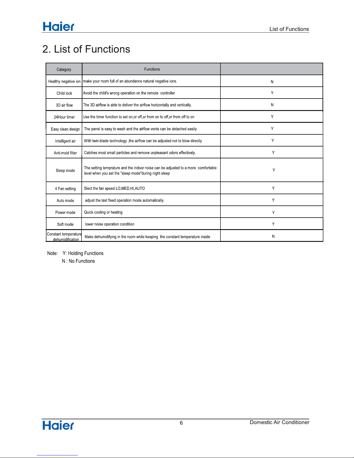
2. List of Functions ……………………………………………………………………………..6
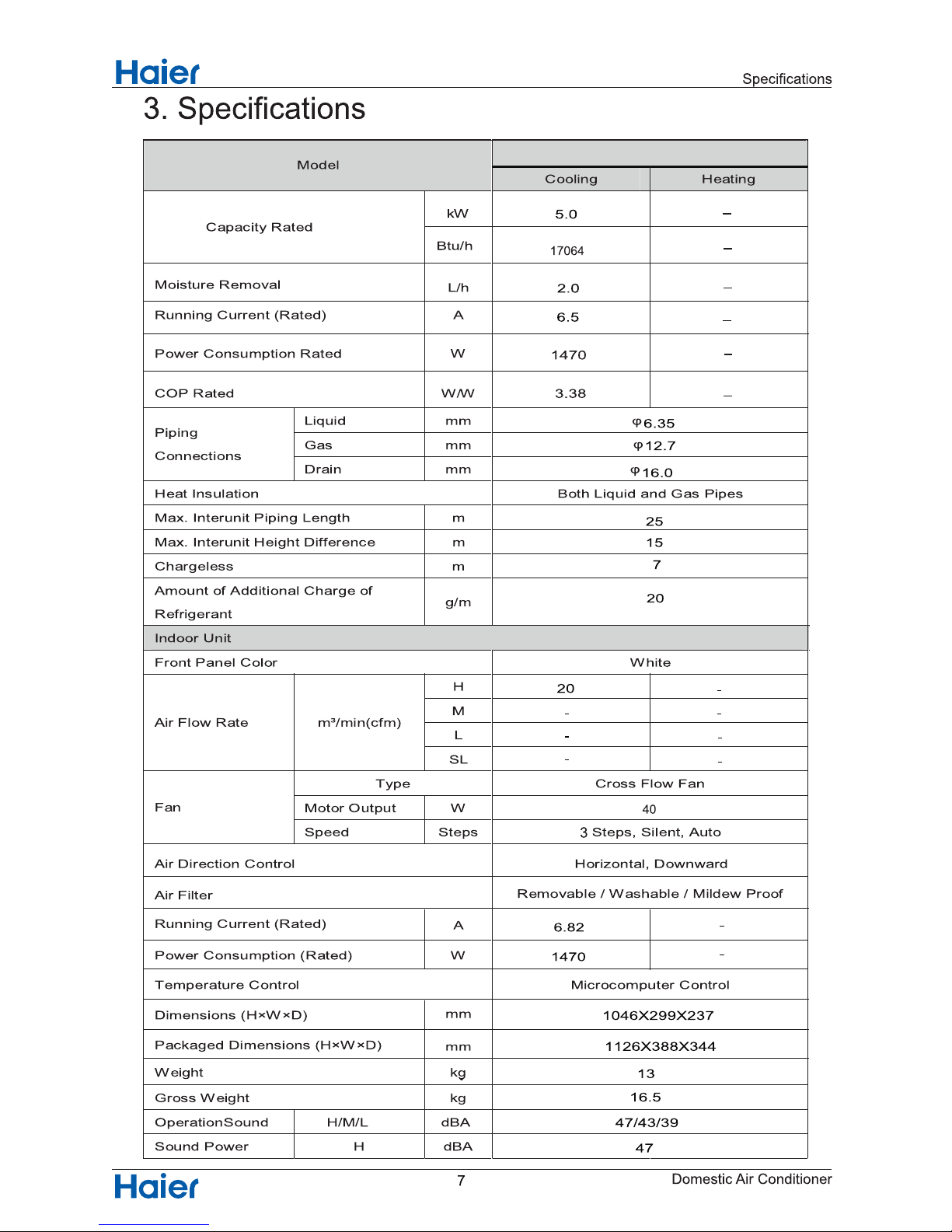
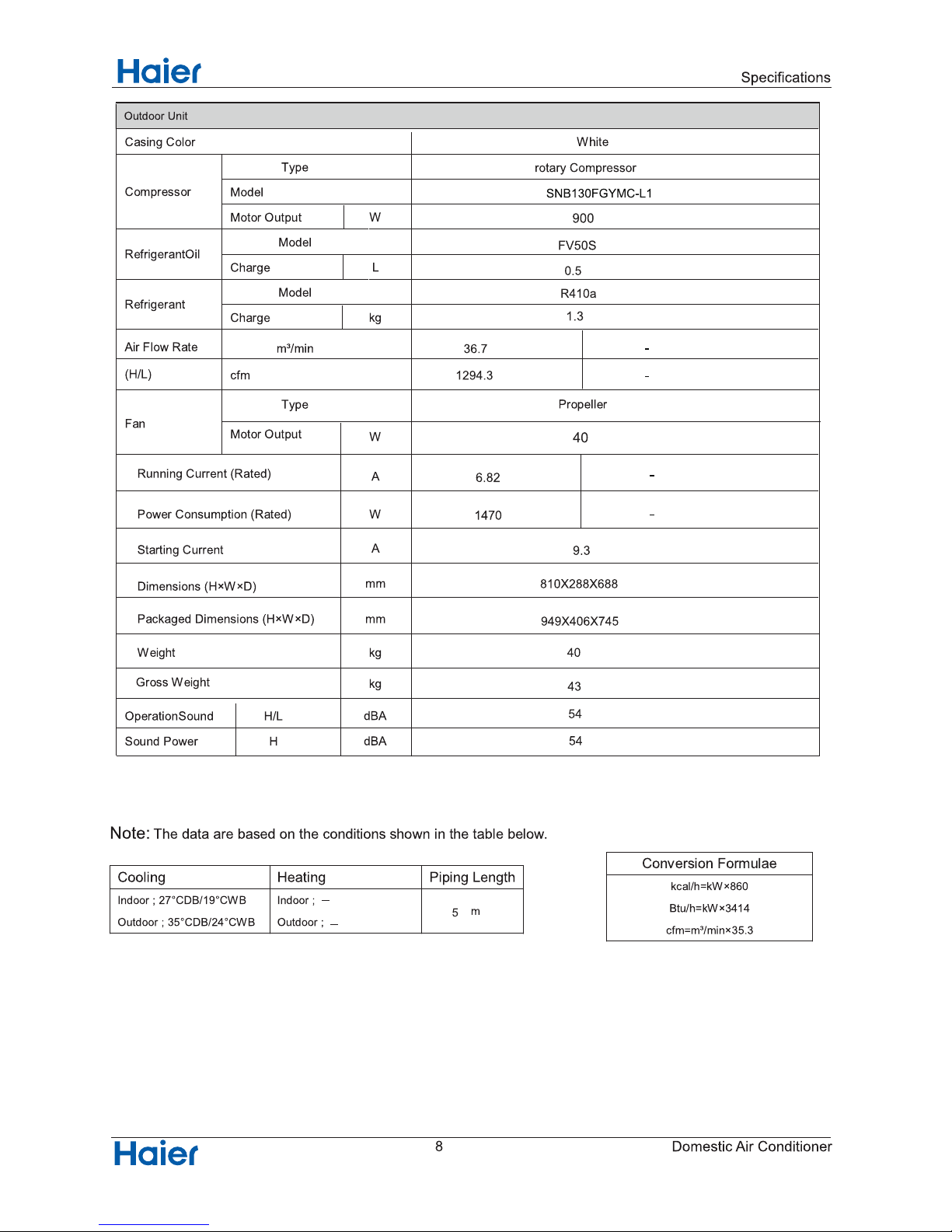
3. Specifications ……………………………………………………………………………….. 7
4. Printed Circuit Board ConnectorWiring Diagram …………………………………….. 9
5. Functions and Control ……………….....………………………..…………….……….....14
5.1 Main functions and control specifications of indoor unit …….………...........………….14
5.2 Main functions and control specifications of outdoor unit ……………....………………21
5.3 Value of Thermistor …………………………………............………..…………………….25
6. System Configuration …………………………….………………………………….…….
37
6.1 System Configuration……………………………………..……………………..……...…37
6.2 Instruction …………….…………….………………………………………………………37
7. Error Codes and Descirption..……………………………………………………………..
45
8. Installations ………………………………………………….……………………………….
60
9. Removal Procedure………………………………………..……………………………...…
65
9.1 Removal of Indoor Unit………………………………..………….……..…………………65
9.2 The removal procedure of outdoor……….……..…….……..…………………………...
77
10.Wiring Diagrams ……………………………………………….…………………………….90
10.1 Indoor Unit …………………………………………………..…………………………….90
10.2 Outdoor Unit ………………………….………………………………………………..….91
11.Circuit Diagrams …………………………………………….……………………………….92
12.Description of Coding rules of Unit Model ……………….……………………………..
95
Introduction
Domestic Air Conditioner
1. Introduction
1.1 Safety Cautions
Be sure to read the following safety cautions before conducting repair work.
The caution items are classified into “Warning” and “Caution”. The “Warning” items are especially important
since they can lead to death or serious injury if they are not followed closely. The “Caution” items can also lead
to serious accidents under some conditions if they are not followed. Therefore, be sure to observe all the safety
caution items described below.
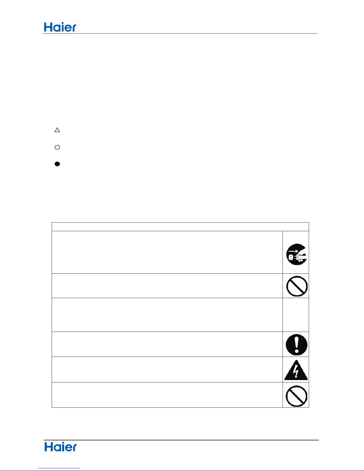
About the pictograms
This symbol indicates an item for which caution must be exercised.
The pictogram shows the item to which attention must be paid.
This symbol indicates a prohibited action.
The prohibited item or action is shown inside or near the symbol.
This symbol indicates an action that must be taken, or an instruction.
The instruction is shown inside or near the symbol.
After the repair work is complete, be sure to conduct a test operation to ensure that the equipment operates
normally, and explain the cautions for operating the product to the customer.
1.1.1 Caution in Repair
Warning
Be sure to disconnect the power cable plug from the plug socket before disassembling the equipment for
arepair.
Working on the equipment that is connected to a power supply can cause an electrical shook.
If it is necessary to supply power to the equipment to conduct the repair or inspecting the circuits, do not
touch any electrically charged sections of the equipment.
If the refrigerant gas discharges during the repair work, do not touch the discharging refrigerant gas.The
refrigerant gas can cause frostbite.
When disconnecting the suction or discharge pipe of the compressor at the welded section, release the
refrigerant gas completely at a well-ventilated place first.
If there is a gas remaining inside the compressor, the refrigerant gas or refrigerating machine oil
discharges when the pipe is disconnected, and it can cause injury.
If the refrigerant gas leaks during the repair work, ventilate the area. The refrigerant gas can generate
toxic gases when it contacts flames.
The step-up capacitor supplies high-voltage electricity to the electrical components of the outdoor unit.
Be sure to discharge the capacitor completely before conducting repair work.A charged capacitor can
cause an electrical shock.
Do not start or stop the air conditioner operation by plugging or unplugging the power cable plug.
Plugging or unplugging the power cable plug to operate the equipment can cause an electrical shock or
fire.
1
Introduction
Domestic Air Conditioner
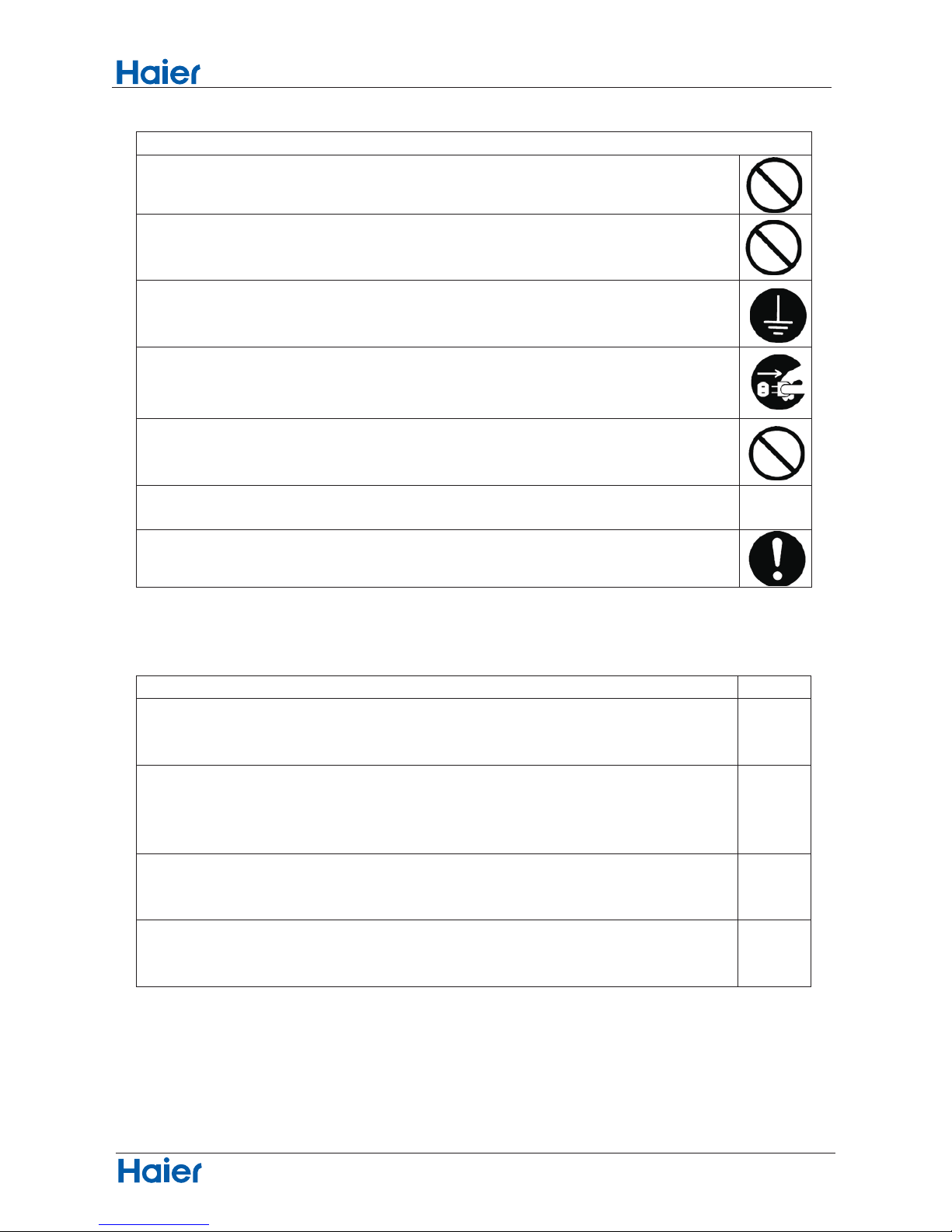
Warning
Do not repair the electrical components with wet hands. Working on the equipment with wet hands can
cause an electrical shock.
Do not clean the air conditioner by splashing water. Washing the unit with water can cause an electrical
shock.
Be sure to provide the grounding when repairing the equipment in a humid or wet place, to avoid electrical
shocks.
Be sure to turn off the power switch and unplug the power cable when cleaning the equipment. The
internal fan rotates at a high speed, and cause injury.
Do not tilt the unit when removing it. The water inside the unit can spill and wet the furniture and floor.
Be sure to check that the refrigerating cycle section has cooled down sufficiently before conducting repair
work. Working on the unit when the refrigerating cycle section is hot can cause burns.
Use the welder in a well-ventilated place. Using the welder in an enclosed room can cause oxygen
deficiency.
1.1.2 Cautions Regarding Products after Repair
Warning
Be sure to use parts listed in the service parts list of the applicable model and appropriate tools to
conduct repair work. Never attempt to modify the equipment. The use of inappropriate parts or tools can
cause an electrical shock, excessive heat generation or fire.
When relocating the equipment, make sure that the new installation site has sufficient strength to
withstand the weight of the equipment.
If the installation site does not have sufficient strength and if the installation work is not conducted
securely, the equipment can fall and cause injury.
Be sure to install the product correctly by using the provided standard installation frame.
Incorrect use of the installation frame and improper installation can cause the equipment to fall, resulting
in injury.
For
integral
units only
Be sure to install the product securely in the installation frame mounted on a window frame.
If the unit is not securely mounted, it can fall and cause injury.
For
integral
units only
2
Introduction
Domestic Air Conditioner
Warning
Be sure to use an exclusive power circuit for the equipment, and follow the technical standards related to
the electrical equipment, the internal wiring regulations and the instruction manual for installation when
conducting electrical work.
Insufficient power circuit capacity and improper electrical work can cause an electrical shock or fire.
Be sure to use the specified cable to connect between the indoor and outdoor units. Make the
connections securely and route the cable properly so that there is no force pulling the cable at the
connection terminals.
Improper connections can cause excessive heat generation or fire.
When connecting the cable between the indoor and outdoor units, make sure that the terminal cover does
not lift off or dismount because of the cable.
If the cover is not mounted properly, the terminal connection section can cause an electrical shock,
excessive heat generation or fire.
Do not damage or modify the power cable.
Damaged or modified power cable can cause an electrical shock or fire. Placing heavy items on the
power cable, and heating or pulling the power cable can damage the cable.
Do not mix air or gas other than the specified refrigerant (R-410A / R22) in the refrigerant system.
If air enters the refrigerating system, an excessively high pressure results, causing equipment damage
and injury.
If the refrigerant gas leaks, be sure to locate the leak and repair it before charging the refrigerant. After
charging refrigerant, make sure that there is no refrigerant leak.
If the leak cannot be located and the repair work must be stopped, be sure to perform pump-down and
close the service valve, to prevent the refrigerant gas from leaking into the room. The refrigerant gas itself
is harmless, but it can generate toxic gases when it contacts flames, such as fan and other heaters,
stoves and ranges.
When replacing the coin battery in the remote controller, be sure to disposed of the old battery to prevent
children from swallowing it.
If a child swallows the coin battery, see a doctor immediately.
3
Introduction
Domestic Air Conditioner
1.1.3 Inspection after Repair
Warning
Check to make sure that the power cable plug is not dirty or loose, then insert the plug into a power outlet
all the way.
If the plug has dust or loose connection, it can cause an electrical shock or fire.
If the power cable and lead wires have scratches or deteriorated, be sure to replace them.
Damaged cable and wires can cause an electrical shock, excessive heat generation or fire.
Warning
Do not use a joined power cable or extension cable, or share the same power outlet with other electrical
appliances, since it can cause an electrical shock, excessive heat generation or fire.
Caution
Installation of a leakage breaker is necessary in some cases depending on the conditions of the
installation site, to prevent electrical shocks.
Do not install the equipment in a place where there is a possibility of combustible gas leaks.
If a combustible gas leaks and remains around the unit, it can cause a fire.
Be sure to install the packing and seal on the installation frame properly. If the packing and seal are not
installed properly, water can enter the room and wet the furniture and floor.
For
integral
units only
4
Introduction
Domestic Air Conditioner
Caution
Check to see if the parts and wires are mounted and connected properly, and if the connections at the
soldered or crimped terminals are secure. Improper installation and connections can cause excessive
heat generation, fire or an electrical shock.
If the installation platform or frame has corroded, replace it. Corroded installation platform or frame can
cause the unit to fall, resulting in injury.
Check the grounding, and repair it if the equipment is not properly grounded. Improper grounding can
cause an electrical shock.
Be sure to measure the insulation resistance after the repair, and make sure that the resistance is 1 M
ohm or higher.
Faulty insulation can cause an electrical shock.
Be sure to check the drainage of the indoor unit after the repair.
Faulty drainage can cause the water to enter the room and wet the furniture and floor.
5
HSU-18LEK03/R2(DB)
HSU-18LEK03/R2(DB)
HSU-18LEK03/R2(DB)
HSU-18LEK03/R2(DB)
Connector Wiring Diagram
10
Domestic Air Conditioner
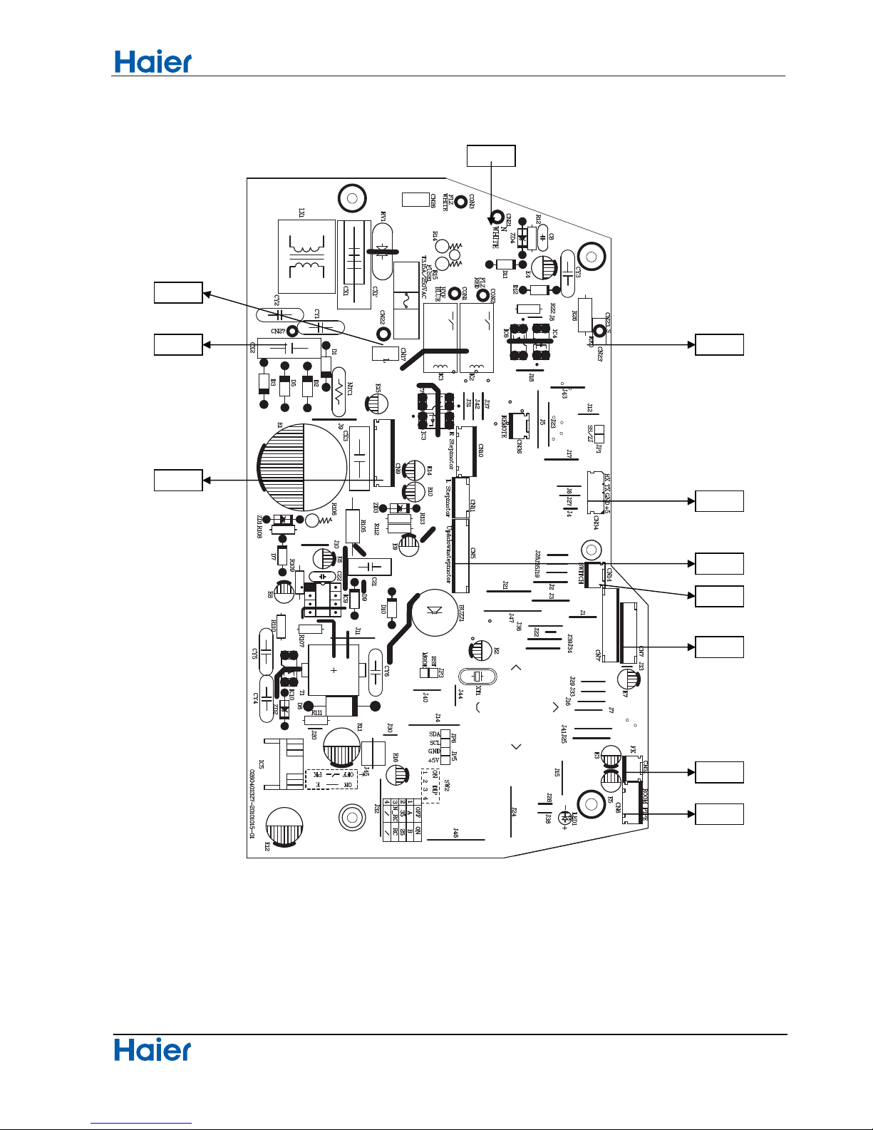
PCB(1)
CN5
CN21
CN27 CN23
CN22
CN7
CN6
CN34
CN51
CN9
CN14
Connector Wiring Diagram
11
Domestic Air Conditioner
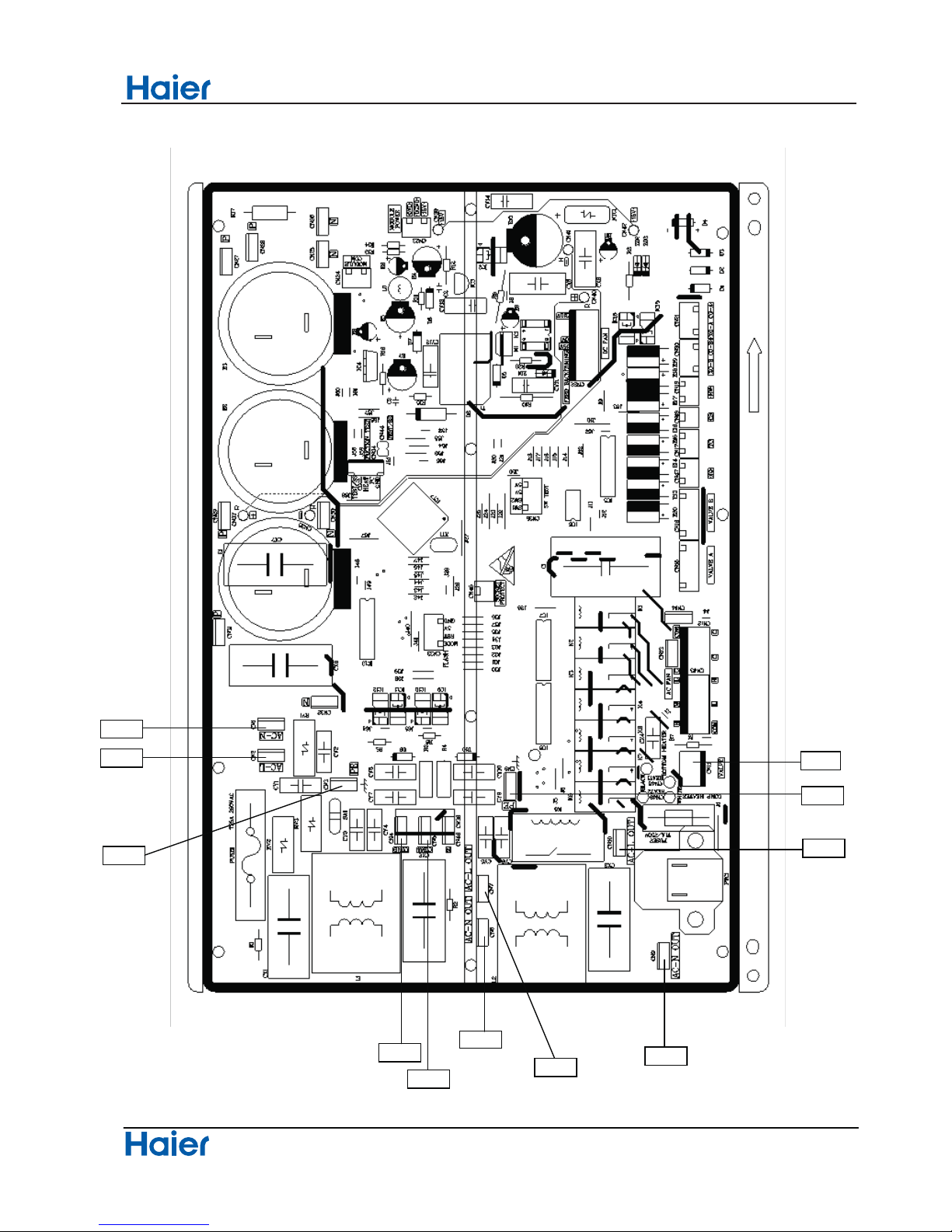
4.2 outdoor unit
Connectors
PCB(1) (Control PCB)
1) CN1,CN2 Connector for power N and L
2) CN3
CN8 Connector for ground
3) CN23 Connector for DC POWER 15Vand 5V to the module board
4) CN9,CN10 Connector for CN9,CN8 on the module board
5) CN22 Connector for fan motor
6) CN11 Connector for four way valve coil
7) CN17,CN18,CN19,CN20,CN21
CN47 Connector for thermistors
8) CN24 Connector for communicate between the control board and the module board
9) CN28,CN25 Connector to P and N of the module board
10) CN14 Connector for communicate between indoor and outdoor unit
11) CN15
CN16 Connector for electric expansion valves
PCB(2) (module PCB)
CN11 Connector for the DC power 5V and 15V form the control PCB
CN10 Connector for communicate between the control board and the module board
P( CN8), N(CN9) Connector for capacitance board
LI (CN3),LO(CN4) Connector for reactor
AC_L(CN1),AC_N(CN2) Connector for control board
CN5
CN6 CN7 Connector for the U, V, W wire of the
compressor
Note: Other Designations
PCB(1) (Control PCB)
1) FUSE 1, (25A,250VAC) FUSE 2(1A,250VAC)
2)LED 1 keep light representative normal ,if keep flash interval representative trouble Alarm
3)RV1,RV2,RV3 Varistor

Connector Wiring Diagram
Domestic Air Conditioner
CN36
CN17
CN28CN23
CN18
CN16
CN9
CN8
CN10
CN3
CN11
CN15
CN24 CN25
CN19
CN20
CN1
CN2
CN47
CN49
CN45
CN14
CN21
CN22
12
Connector Wiring Diagram
13
Domestic Air Conditioner
PCB(2)
CN6
CN5
CN1
CN2
CN3
CN4
CN7
CN8
CN9
CN10
CN11
14
Domestic Air Conditioner
5.Funcitions and Control
5.1 Main functions and control specification of indoor unit
5.1.1 Automatic operation
When the running mode is turned to automation after starting the system, the system will first
determine the running mode according to the current room temperature and then will run according to
the determined mode. Tr in the following selection conditions means room temperature, Ts means
setting temperature, Tp means temperature of indoor coil pipe
Tr≥23
Choose Cooling Mode
Tr
23 Choose Heating Mode
After turning to the automation mode, the running mode can be switched between cooling mode,
fan mode and heating mode according to the change of the indoor ambient temperature. But the
automatic conversion between cooling mode and heating mode must be conducted after 15 minutes.
5.1.2 Cooling operation mode
Temperature control range: 16 ---30
Temperature difference: ±1
* Control features: When Tr input airflow >Ts set temperature , the compressor will be opened,the
indoor fan will operate at the set speed and the mode signal will be sent to the outdoor system. When
Tr
input airflow
<Ts set temperature , the compressor will be opened,the indoor fan will operate
at the set speed and the mode signal will be sent to the outdoor system. The system will keep the
original status if Tr= Ts.
Airflow speed control: (temperature difference 1
)
Automatic: When Tr≥Ts+3
,highspeed.
When Ts+1
≤Tr<Ts+3 ,mediumspeed
When Tr<Ts+1
, low speed
Whenthesensorisoff,lowspeed
When the airflow speed has no delay from the high to low switching, the speed should be delayed for
3 minutes (remain at high speed for 3 minutes.) before the next switch.
Manus: When the system is operating, you can set the high, medium or low speed manually. ( When
the sensor is on or off, the system will change the speed 2 seconds after receiving the signal.)
*Airgate location control: the location for the airgate can be set according to your needs.
*Defrosting function: preventing the frosting on the indoor heat exchanger (when cooling or
demoisture). When the compressor works continuously for 1/6 minutes (adaptable in EEPROM) and
the temperature of the indoor coils has been below zero centigrade for 10 seconds, the compressor
will be stopped and the malfunction will be recorded in the malfunction list. The indoor system will
continue to run. When the temperature of the indoor coil is raised to 7
, the compressor will be
restarted again (the prerequirement of 3 minutes’ delay should be satisfied.)
* timing system on/off function.
* Dormant control function.
Functions and Control
15
Domestic Air Conditioner
5.1.3 Demoisture mode.
* temperature control range: 16---30
* temperature difference: ±1
Control feature: send the demoisture signal to the outdoor system.
When Tr>Ts+2
, the compressor will be turned on, the indoor fan will operate at the set speed.
When Tr is between the Ts and Ts+2
, the outdoor system will operate at the high demoisture
frequency for 10 minutes and then at the low demoisture mode for six minutes. The indoor fan will
operate at low speed.
When Tr< Ts, the outsystem will be stopped, the indoor fan will be stopped for 3 minutes and then
turned to the low speed option.
All the frequency converses have a
1 difference.
* Wind speed control: Automatic:
When Tr ≥Ts + 5
, high speed.
When Ts+3
≤Tr< Ts+5 , medium speed.
When Ts+2
≤Tr< Ts+3 , low speed.
When Tr<Ts+2
, light speed.
If the outdoor fan stopped, the indoor fan will be paused for 3 minutes.
If the outdoor fan stopped for more than 3 minutes and the outdoor system still operates, the system
will be changed into light speed mode.
When the airflow speed has no delay from the high to low switching, the speed should be delayed for
3 minutes (remain at high speed for 3 minutes.) before the next switch.
Manual: When the sensor is off or Tr< Ts+3
, the manual operation can not be made. (obligatory
automatic operation.)
*Airgate location control: the location for the airgate can be set according to your needs.
*Defrosting function: preventing the frosting on the indoor heat exchanger (when cooling or
demoisture). When the compressor works continuously for 1/6 minutes (adaptable in EEPROM) and
the temperature of the indoor coils has been below zero centigrade for 10 seconds, the compressor
will be stopped and the malfunction will be recorded in the malfunction list. The indoor system will
continue to run. When the temperature of the indoor coil is raised to 7
, the compressor will be
restarted again (the prerequirement of 3 minutes’ delay should be satisfied.)
* coil protection (synchronic overheating protection) are installed for the four directions latch
malfunctions when demoisturing.
* timing system on/off function.
* Dormant control functio
n.
Functions and Control
5.1.4 strength operation
a. the system enters the mode after receiving the ‘strength signal’.
Send strength operation signal to the outdoor system.
The mode change finishes the strength operation.
Entering ‘mute’, you can have normal operation or signal control such as timing to finish the strength
operation.
Functions and Control
16
Domestic Air Conditioner
When the system is at the automatic option with the strength/ mute function, if the system enters the
cooling mode, the cooling strength/ mute function will be offered; if the system enters the heating
mode, then the heating strength/ mute function will be offered; if the system enters the airflow mode,
there will be no strength/ mute function.
5.1.5 Mute operation
the system enters the mode after receiving the ‘mute signal’.
a. Mute heating: the airflow speed is slight, the system sends the mute signal to the outdoor system.
b. mute cooling: the airflow speed is slight, the system sends the mute signal to the outdoor system.
When the compressor operates, the airflow speed is mute speed. EEPROM is adaptable.
Mute operation can not work under the demoisturing and airflow-sending operation.
5.1.6 Air refreshing
After receiving the signal from the remote control,(HV series: the background light of the ‘health’ logo
is green. HS series: the ‘health’ indicator will be lighted). If the fan operates, the negative ion
generator operates to realize the negative sending function.
If the indoor fan stops, the negative ion generator is turned off.
When the negative ion generator is turned off, if the air refreshing system is turned on, the negative
ion generator will be turned on when the fan operates.
5.1.7 Timing.
You can set 24 hours’ on/off timing accordingly. After the setting, the timing indicator will be lightened.
Also, the light will be turning off after the timing is finished. The followings are several timing methods.
1.system /on timing: The timing indicator will be lightened and the indoor system is under the waiting
mode. The light will be turned off when the timing is finished and the rest of the system will operate
under a normal condition. The timing starts since the last reception of the timing singal. You can have
the dormacy setting under the timing mode, the order of your settings will be operated according to
the timing settings.
2.system /off timing: When the system is turned on, the timing indicator is lightened, the rest of the
system will operated under a normal condition. When set time comes, the indicator light will be turned
off and the system will be turned off. If you have set the dormant functions, the order of your settings
will be operated according to the timing settings.
3 .system /on and off timing: The settings will be completed according to the orders.
5.1.8 Dormant operation
The dormant timing is an eight hours unadaptable one. The timing signs are shown on the V series
board. (RC series show the dormant signal, the timing light is lighted on the 6 lights board).
2.1 Under the cooling/ demoisture operation, after the setting of the dormant operation, the set
Functions and Control
17
Domestic Air Conditioner
temperature will be raised for 1 centigrade after 1 hour’s operation and will be raised for 1 centigrade
1 hour later. The system will keep this status for 6 hours and then close.
2.2 Under the heating mode, after the setting of the dormant operation, the et temperature will fall 2
centigrades after 1 hour’s operation and will fall 2 centigrades 1 hours later. 3 hours after the
preceding operations, the set temperature will be raised for 1 centigrade and the system will keep this
status for 3 hours and then close down.
2.3 During the dormant time, except the change of the system mode or a new press on the dormant
setting keys, the timing of the 8 hours dormancy will take the first timing as the start time, any presses
on other keys will not affect the original timing.
2.4 Indoor fan control under the dormant operation.
If the indoor fan is at the high speed before the dormant operation setting, the speed will be turned to
medium after the setting. If the fan is at the medium speed before the dormant setting, the speed will
be turned to low after the setting. If the fan is at the low speed before the dormant setting, the speed
will not change.
5.1.9 Urgent on/off input
Press the urgency button the buzzer will ring. The system will enter the automatic mode if you don’t
press the button for more than 5 seconds.
Under the system off mode, if you press the urgency key for 5 to 10 seconds, the system will start the
test operation.
Under the system off mode, If you press the urgency key for 10 to 15 seconds, the display screen will
show the resume of the last malfunction.
If the system is under operation, the press on the urgency key will stop it.
Under the system off mode, the display screen will show automatic running sign.
Under the system off mode, the system will not receive the remote control signal if the press on the
urgency key doesn’t last for 15 seconds or if the key is loosened.
Urgency operation: If you press the urgency key for less than 5 seconds, the buzzer will ring when you
press the on/off key. The system will enter the urgency operation when the urgency key is loosened.
The urgency operation is fully automatic.
Test operation.
The inlet temperature sensor doesn’t work, the indoor fan and the indoor air direction board motor
works synchronically. High speed airflow, cooling, outdoor system on, etc, will send the ambient
temperature 30 centigrade and coil temperature 16 centigrade information to the outdoor system.
Test operation
The defrost protection of the evaporator doesn’t work.
The temperature control doesn’t work.
The test operation will be finished in 30 minutes.
The test operation can be stopped by the relative commands from the remote control.
5.1.10 Low load protection control
In order to prevent the frosting of the indoor heat interaction device, the outdoor system will be
stopped if the indoor heat interaction temperature is below zero centigrade for 5 minutes, but the fan
Functions and Control
18
Domestic Air Conditioner
will continue to operate. The outdoor system will be started again when the heat interaction
temperature is above 7 centigrade and the system has been stopped for 3 minutes. The malfunction
will be stored in the malfunction resume and will not be revealed.
5.1.11 High load protection control
The outdoor system will be stopped if the coil temperature is above 65 for 2 minutes. The indoor
fan will be controlled by the thermostat. The outdoor system can be restarted when the coil
temperature is below 42
and the system has been stopped for 3 minutes. The malfunction will be
stored in the malfunction resume and will not be revealed.
5.1.12 abnormal operation of indoor system
When the outdoor system operates, if the indoor system operation differs from the outdoor system,
the abnormal operation malfunction will be reported. 10s after the report, the indoor system will be
closed.
Outdoor system mode Indoor system mode conflicts
cooling heating yes
cooling cooling no
cooling airflow no
heating heating no
heating airflow yes
heating cooling yes
5.1.13 Malfunction list resume.
Nothing is presented if there is no code list.
The malfunction display will automatically finish in 10 seconds.
The remote control only receives the sigals for stop. According to the signals, the malfunction resume
presentation finishes.
The resume restores after the power supply restores.
5.1.14 abnormality confirmation approaches.
1. indoor temperature sensor abnormality:
under the operation, the normal temperature ranges from 120 degree to -30 degree. When the
temperature goes beyond this range, the abnormality can be confirmed. If the temperature goes back
into the range, the system will automatically resume.
2 .indoor heat interaction sensor abnormality:
under the operation, the normal temperature ranges from 120 degree to -30 degree. When the
temperature goes beyond this range, the abnormality can be confirmed. If the temperature goes back
into the range, the system will automatically resume.
Functions and Control
19
Domestic Air Conditioner
3 .indoor malfunction:
Out door malfunction: When the indoor system receives the outdoor malfunction codes, it will store
the code into E2 for the malfunction list resume. The indoor system will continue to operate according
to the original status, the malfunction code will not be revealed or processed.
4.transmission abnormality:
If the indoor system can’t receive the outdoor system for 8 minutes, the communication abnormality
can be confirmed and reported and the outdoor system will be stopped.
5.1.15 Single indoor system operation
* Enter condition: First, set the high speed airflow and 30 centigrade set temperature, then press the
dormant keys for 6 times within 7 seconds, the system will feedback with 6 rings.
* After the system enters the separate indoor system operation mode, the indoor system will operate
according to the set mode and neglect the communication signals of the outdoor system. However, it
has to send signals to the outdoor system.
* Quitting condition: This mode can be quitted after receiving the quitting signal from the remote
control or urgency system. The indoor system thus can quit the single operation mode.
5.1.16 Power cut compensation.
* Entering condition: Press dormant button 10 times within 7 second, the buzzer will ring 4 times and
the present system status will be stored into the EEPROM of the indoor system.
* After entering the power cut compensation mode, the processing of the indoor system should be as
the followings:
Remote control urgency singal: operate according to the remote control and the urgent conditions,
the present status will be stored into the EEPROM of the indoor system.
* Quitting conditions: Press dormant button 10 times within 7 seconds and the buzzer will ring twice.
5.1.17 Fixed frequency operation.
1. Fixed cooling: a. under G code condition: high speed cooling, set 16 , press temperature ‘-‘ key
and the set key at the same time. The system will enter the fixed frequency operation after the buzzer
rings twice.
b. The proceeding programs are as the follows:
Entering the fixed frequency operation, you can set the fixed strength location 1 and send the coolng
signal to the outdoor system. Meanwhile, you can fix the indoor system at high speed mode, the
location of the airflow directin board can be switched to the maximal position.
c. Quitting condition: The fixed frequency cooling can be quitted after receiving the remote signal, and
the system will enter the remote setting status.
2. Fixed heating: a. under G code condition: high speed heating, set 30
, press temperature ‘+‘ key
and the set key at the same time. The system will enter the fixed frequency operation after the buzzer
rings twice.
b. The proceeding programs are as the follows:
Functions and Control
20
Domestic Air Conditioner
Entering the fixed frequency operation, you can set the fixed strength location 1 and send the heating
signal to the outdoor system. Meanwhile, you can fix the indoor system at high speed mode, the
location of the airflow directin board can be switched to the maximal position.
c. Quitting condition: The fixed frequency heating can be quitted after receiving the remote signal, and
the system will enter the remote setting status.
5.1.18 Test program
First, connect the test program terminal on the mainboard, then connect the system to the power
circuit. The test program will operate as follows.
HV series display: The buzzer rings for one time—the signal will be sent to outdoor system for 0.5
second— the violet is sent for 0.5-- the background light turns to white—the back ground light turns to
white—the background light turns to white—the background light is fully lighted for 0.5 second—LED
screen lights for 0.5 second— the step-in motor fully output for 0.5 second—then the motor doesn’t
output for 0.5 second—the motor fully output again for 0.5 second. The test program finishes.
5.1.19 Time cutting function:
connect the test program terminal on the mainboard after connecting the system to the power circuit.
The CPU of the main control will be 60 times faster.

Functions and Control
21
Domestic Air Conditioner
5.2 The control system of outdoor unit
5.2.1 The operation frequency of outdoor unit and its control
5.2.1.1 The operation frequency control of compressor
The operation frequency scope of compressor
Mode Minimun operation frequency Maximun operation frequency
zH02
zH09
noitaregirfeR
5.2.1.2 The starting of compressor
When the compressor is started for the first time, it must be kept under the conditions of
58Hz,88Hz for one minute (the overheating protection of the outdoor unit air-blowing temperature,
immediately decrease the frequency when the compressor is overflowing and releasing the
pressure)
then it can be operated towards the target frequency. When the machine runs normally,
there’s no such process. After starting the compressor for operation, the compressor should run
according to the calculated frequency, and every determined frequency for protection should be prior
to the calculated frequency.
5.2.1.3 The speeds of increasing or decreasing the frequency of the compressor
The speed of increasing or decreasing the frequency rapidly 1 -----------1HZ/second
The speed of increasing or decreasing the frequency slowly 2 -----------1HZ/10seconds
5.2.1.4 The calculation of the compressor’s frequency
1 The minimum/maximum frequency limitation
While refrigerating:
is the maximum operation frequency of the compressor;
IN is the minimum operation frequency of the compressor.
1
The frequency limitation which is affected by the environment temperature.
Refrigeration/dehumidification mode::
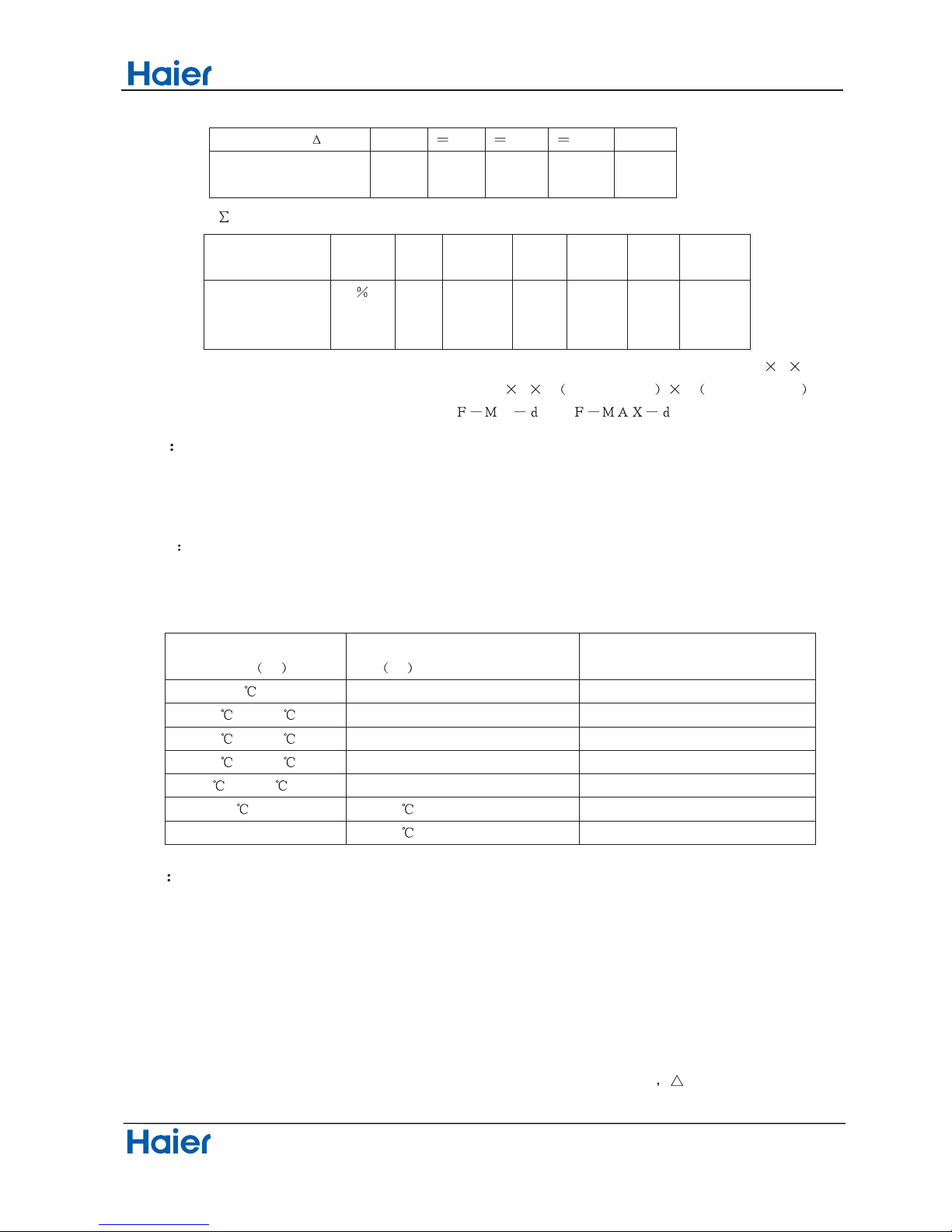
Serial No. Temperature scope Frequency limitation
ZH541zh_xaM82<c_hW1
ZH082zh_xaM23<c_hW2
ZH093zh_xaM04<c_hW3
ZH084zh_xaM84<c_hW4
5
Wh_c
≥
48
Max_hz5 60 HZ
Remarks: the above are not only the maximum frequency limitations of the complete appliance which
are affected by the environment, but also the maximum ability limitation of the system. When the
starting ability is not the maximum, its maximum frequency limitation is calculated by the following
equations:
The frequency limitation which is affected by the temperature and under the condition of actual ability
the actural running system ability*the maximum frequency which is limited by the temperature and
under the condition of maximum ability/the maximum designing ability of the system
T= Ti*Pi / Pi ( Ti=|Tst_i-Tnh_i the indoor environment temperature| ;Pi i the ability of
the indoor unit)
Functions and Control
22
Domestic Air Conditioner
Refrigeration/dehumidification:
K=
Ki/the number of running machines
The calculation of the actual output frequency: when there is no healthy airflow: F =F-ED-*
P K
When the healthy airflow has been set: F =F-ED-*
P K airflow speed K healthy airflow
When refrigerating, it is needed to satisfy IN <F<
5.2.2 The outdoor fan control (exchange fan)
When the fan is changed among every airflow speed (including stop blowing), in order to avoid the
airflow speed from skipping frequently, it must be kept under each mode for over 30 seconds, and
then it can be changed to another mode (when refrigerating, the time is changed to 15 seconds).
5.2.2.1 The outdoor fan control when refrigerating or dehumidifying
After the compressor is started for 5 seconds, the outdoor fan is started at the medium speed at first,
after 30 seconds,it begins to control the airflow speed according to the temperature conditions of the
outdoor environment.
T
<1
1 2 3
≥
4
The percentage of the
rated frequency P
50% 70% 100% 120% 140%
The indoor set
airflow speed
Breeze Low Medium High Strong Quiet Healthy
airflow
The percentage
of the rated
frequency Ki
65
70% 90% 100% 180% 65% 70%
The temperature of the
outdoor air
Ta
The temperature of the outdoor
coil
Te
Airflow speed
Ta ≥30
hgiH——
26 ≤Ta <3 0
deepsehtgnipeeK——
24 ≤Ta <2 6
muideM——
23 ≤Ta <2 4
deepsehtgnipeeK——
5 ≤Ta<23
woL——
Ta <5 15 ≤Te
Low
15 >Te
Stop
5.2.3 The control of the outdoor electronic expansion valve
When starting the compressor: the opening size of the valve must be guaranteed to have entered into
the standard opening size, and then the compressor can be started.
When refrigeration is in vain (the machine is shut down or is in the state of retrograde operation), the
opening size of the expansion valve of the indoor unit is 5 steps;
When heating is in vain, the opening size of the expansion valve of the indoor unit is 55 steps;
When the outdoor unit is shut down, the valve is opened completely for 2 minutes, and then begin
initialization.
The scope of refrigerationg valve 90-----480 steps
The valves are adjusted according to the degree of superheat —SHa
SHa.
23
Domestic Air Conditioner
5.2.5.1 TTC high temperature-preventing protection
Once the machine is started, it can run TTC overheating protection of air-blowing, but air-blowing
sensor malfunction must alarm after 4 minutes during which the compressor is started (during the
course of self-detection, there’s no such limitation)
Sensor detection methods: 100 times (one cycle of procedure run is one time, and about 5ms,
detection method for each time: continuously sampling for 8 times, then order them and take the
mean value of the middle 2 values), take the mean value.
TTC
Abnormal stop
110
Decreasing the frequency rapidly
1HZ/second
100
Decreasing the frequency slowly (1HZ/10seconds)
98
The frequency doesn’t change.
93
Increasing the frequency (1HZ/10second)
90
Increasing the frequency
1HZ/1second
TTC>=110 lasts for 20 seconds. Overheating protection of air-blowing, alarm malfunction to the
indoor, others don’t last.
5.2.5 Protection function
Functions and Control
5.2.5.2 The control of preventing the overcurrent of the compressor
During the starting process of the compressor, if the curren of the compressor is greater than 17A
for 3 seconds, stop the compressor and alarm, after 3 minutes, start it again, if such state appears 3
times in 20 minutes, stop the compressor and alarm, and confirm the malfunction. Then continue to
run it only after the the power is off.
During the starting process of the compressor, if the AC current is greater than 12A, the frequency
of the compressor decreases at the speed of 1HZ/second.
During the starting process of the compressor, if the AC current is greater than 10A, the frequency
of the compressor decreases at the speed of 0.1HZ/second.
During the starting process of the compressor, if the AC current is greater than 9A, the frequency of
the compressor increases at the prohibited speed.
During the starting process of the compressor, if the AC current is greater than 8A, the frequency of
the compressor increases at the speed of no faster than 0.1HZ/second.

24
5.2.5.3 The protection function of AC current:
During the starting process of the compressor, if the AC current is greater than 15A, the frequency of
the compressor decreases at the speed of 1HZ/second.
During the starting process of the compressor, if the AC current is greater than 13A, the frequency of
the compressor decreases at the speed of 0.1HZ/second.
During the starting process of the compressor, if the AC current is greater than 11A, the frequency o
f
the compressor increases at the prohibited speed.
During the starting process of the compressor, if the AC current is greater than 10A, the frequency of
the compressor increases at the speed of no faster than 0.1HZ/second.
Remarks: when the outdoor temperature is high, there’s compensation for AC current protection.
(1)
When the outdoor environment temperature is higher than 40
, AC current protection value
decreases by 10AD
(2)
When the outdoor environment temperature is higher than 46
,AC current protection value
decreases by 15AD
(3)
When the outdoor environment temperature is higher than 50
,AC current protection value
decreases by 20AD
Functions and Control
Domestic Air Conditioner
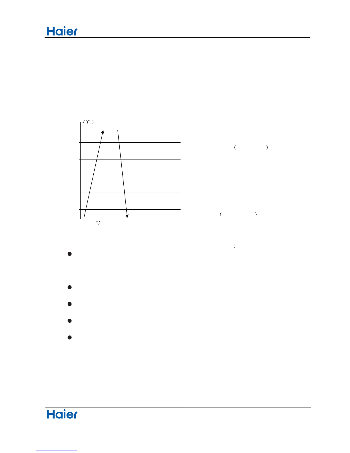
When Tpg_indoor ice_temp_2 , the frequency of the compressor decreases at the speed of
1HZ/10seconds.
When Tpg_indoor begins to rise again, and ice_temp_2≤ Tpg_indoor≤ ice_temp_3
, the frequency
of thecompressor doesn’t change.
When ice_temp_3
Tpg_indoor ice_temp_3+3 , the frequency of the compressor increases at the
speed of 1HZ/10seconds.
For example, Tpg_indoor≤ 0
last for 2 minutes, and then the outdoor unit will stop, and report
underload malfunction, but don’t send malfunction report to the indoor.
The compressor stops for more than 3 minutes, Tpg_indoor> ice_temp_3+2
, the compressor
recovers.
When Tpg_indoor
ice_temp_1 , the frequency of the compressor decreases at the speed of
1HZ/1second.
11
//ice_temp_3+5
9
ice_temp_3+3
Increasing slowly
8
//ice_temp_3+2
Keeping the frequency
ice_temp_3 6
6
ice_temp_2 5 Decreasing slowly
ice_temp_1 3
Decreasing rapidly ice_temp_1
0
Stop
5.2.5.4 Antifreezing protection of the indoor heat exchanger
When refrigerating, prevent freezing.
Tpg_indoor is the minimum value of the effective indoor unit (start it and it is in accord with the
running state).
Functions and Control
Domestic Air Conditioner
25
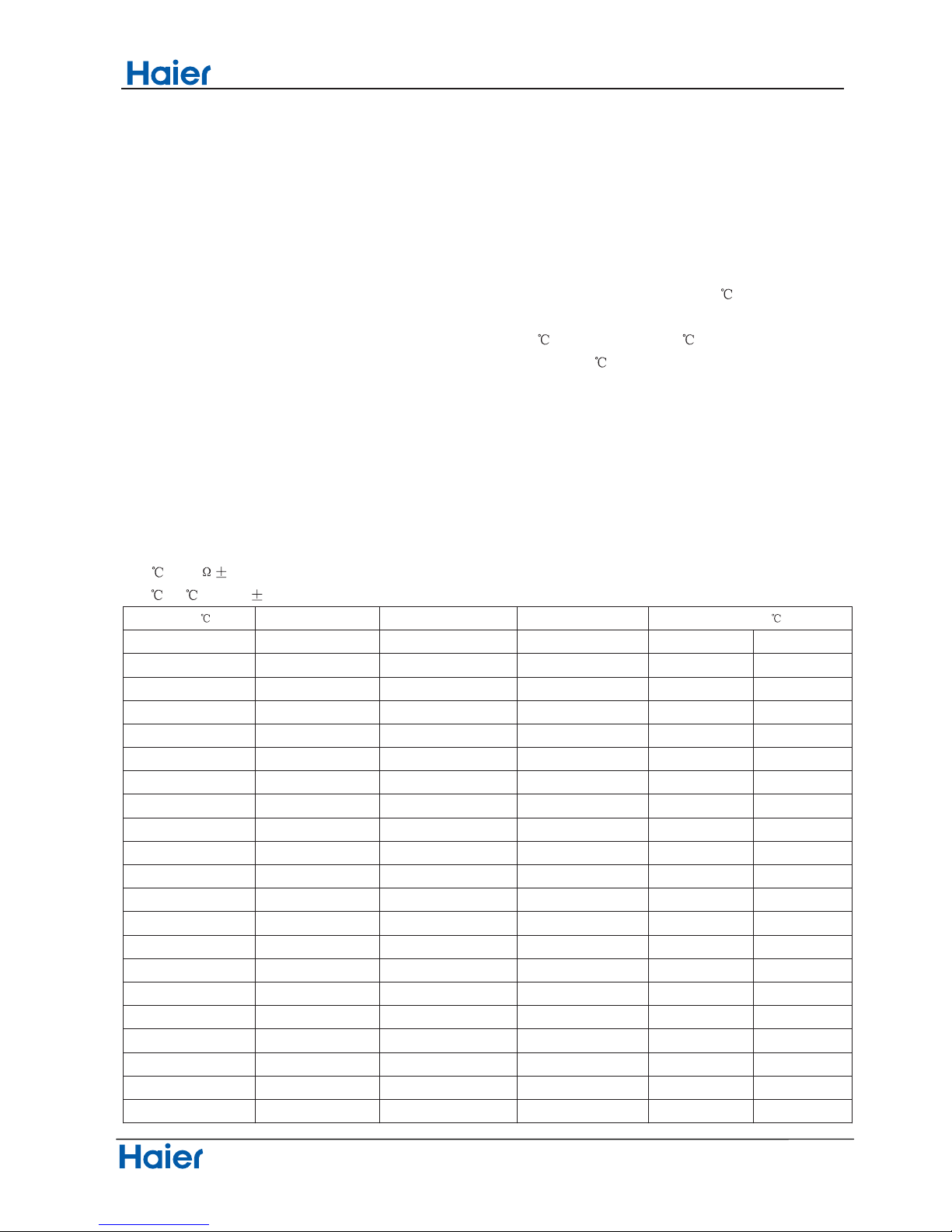
5.3 Value of Thermistor
5.3.1 intdoor Unit
Room sensor and Pipe Sensor
R25 =10K 3%
B25
/50 =3700K 3%
Temp.(( ))
Max.(KΩ) Normal(KΩ) Min.(KΩ)
Tolerance( )
-30 165.2170 147.9497 132.3678 -1.94 1.75
-29 155.5754 139.5600 125.0806 -1.93 1.74
-28 146.5609 131.7022 118.2434 -1.91 1.73
-27 138.1285 124.3392 111.8256 -1.89 1.71
-26 130.2371 117.4366 105.7989 -1.87 1.70
-25 122.8484 110.9627 100.1367 -1.85 1.69
-24 115.9272 104.8882 94.8149 -1.83 1.67
-23 109.4410 99.1858 89.8106 -1.81 1.66
-22 103.3598 93.8305 85.1031 -1.80 1.64
-21 97.6556 88.7989 80.6728 -1.78 1.63
-20 92.3028 84.0695 76.5017 -1.76 1.62
-19 87.2775 79.6222 72.5729 -1.74 1.60
-18 82.5577 75.4384 68.8710 -1.72 1.59
-17 78.1230 71.5010 65.3815 -1.70 1.57
-16 73.9543 67.7939 62.0907 -1.68 1.55
-15 70.0342 64.3023 58.9863 -1.66 1.54
-14 66.3463 61.0123 56.0565 -1.64 1.52
-13 62.8755 57.9110 53.2905 -1.62 1.51
-12 59.6076 54.9866 50.6781 -1.60 1.49
-11 56.5296 52.2278 48.2099 -1.58 1.47
-10 53.6294 49.6244 45.8771 -1.56 1.46
5.2.5.5 The frequency limitation of modification rate
In the field which is controlled by high frequency, if the modification rate is not high enough, the
control-driven chip will enter into weak magnetic control, this will help to relieve the problem of
modification rate. If during the course of weak magnetic control, the modification rate is still not high
enough, enter into the control of decreasing frequency until the alarm of modification rate is relieved.
5.2.5.6 Temperature protection of the outdoor refrigerating coil
When the defrosting temperature and the sensor’s temperature are higher than 65 , the frequency of
the compressor decreases 1hz/10seconds. Keep the frequency until it decreases to the lowest
frequency. When the temperatures are lower than 65
and higher than 60 , keep the frequency of
the compressor. When the temperatures are lower than 60
, relieve the defrosting temperature
protection.
Functions and Control
Domestic Air Conditioner
26
-9 50.8956 47.1666 43.6714 -1.54 1.44
-8 48.3178 44.8454 41.5851 -1.51 1.42
-7 45.8860 42.6525 39.6112 -1.49 1.40
-6 43.5912 40.5800 37.7429 -1.47 1.39
-5 41.4249 38.6207 35.9739 -1.45 1.37
-4 39.3792 36.7676 34.2983 -1.43 1.35
-3 37.4465 35.0144 32.7108 -1.41 1.33
-2 35.6202 33.3552 31.2062 -1.38 1.31
-1 33.8936 31.7844 29.7796 -1.36 1.29
0 32.2608 30.2968 28.4267 -1.34 1.28
1 30.7162 28.8875 27.1431 -1.32 1.26
2 29.2545 27.5519 25.9250 -1.29 1.24
3 27.8708 26.2858 24.7686 -1.27 1.22
4 26.5605 25.0851 23.6704 -1.25 1.20
5 25.3193 23.9462 22.6273 -1.23 1.18
6 24.1432 22.8656 21.6361 -1.20 1.16
7 23.0284 21.8398 20.6939 -1.18 1.14
8 21.9714 20.8659 19.7982 -1.15 1.12
9 20.9688 19.9409 18.9463 -1.13 1.09
10 20.0176 19.0621 18.1358 -1.11 1.07
11 19.1149 18.2270 17.3646 -1.08 1.05
12 18.2580 17.4331 16.6305 -1.06 1.03
13 17.4442 16.6782 15.9315 -1.03 1.01
14 16.6711 15.9601 15.2657 -1.01 0.99
15 15.9366 15.2770 14.6315 -0.98 0.96
16 15.2385 14.6268 14.0271 -0.96 0.94
17 14.5748 14.0079 13.4510 -0.93 0.92
18 13.9436 13.4185 12.9017 -0.91 0.90
19 13.3431 12.8572 12.3778 -0.88 0.87
20 12.7718 12.3223 11.8780 -0.86 0.85
21 12.2280 11.8126 11.4011 -0.83 0.83
22 11.7102 11.3267 10.9459 -0.81 0.80
23 11.2172 10.8634 10.5114 -0.78 0.78
24 10.7475 10.4216 10.0964 -0.75 0.75
25 10.3000 10.0000 9.7000 -0.75 0.75
26 9.8975 9.5974 9.2980 -0.76 0.76
27 9.5129 9.2132 8.9148 -0.80 0.80
28 9.1454 8.8465 8.5496 -0.84 0.83
29 8.7942 8.4964 8.2013 -0.87 0.86
30 8.4583 8.1621 7.8691 -0.91 0.90
31 8.1371 7.8428 7.5522 -0.95 0.93
32 7.8299 7.5377 7.2498 -0.98 0.97
33 7.5359 7.2461 6.9611 -1.02 1.00
34 7.2546 6.9673 6.6854 -1.06 1.04
35 6.9852 6.7008 6.4222 -1.10 1.07
Functions and Control
Domestic Air Conditioner
27
36 6.7273 6.4459 6.1707 -1.13 1.11
37 6.4803 6.2021 5.9304 -1.17 1.14
38 6.2437 5.9687 5.7007 -1.21 1.18
39 6.0170 5.7454 5.4812 -1.25 1.22
40 5.7997 5.5316 5.2712 -1.29 1.25
41 5.5914 5.3269 5.0704 -1.33 1.29
42 5.3916 5.1308 4.8783 -1.37 1.33
43 5.2001 4.9430 4.6944 -1.41 1.36
44 5.0163 4.7630 4.5185 -1.45 1.40
45 4.8400 4.5905 4.3500 -1.49 1.44
46 4.6708 4.4252 4.1887 -1.53 1.47
47 4.5083 4.2666 4.0342 -1.57 1.51
48 4.3524 4.1145 3.8862 -1.61 1.55
49 4.2026 3.9686 3.7443 -1.65 1.59
50 4.0588 3.8287 3.6084 -1.70 1.62
51 3.9206 3.6943 3.4780 -1.74 1.66
52 3.7878 3.5654 3.3531 -1.78 1.70
53 3.6601 3.4416 3.2332 -1.82 1.74
54 3.5374 3.3227 3.1183 -1.87 1.78
55 3.4195 3.2085 3.0079 -1.91 1.82
56 3.3060 3.0989 2.9021 -1.95 1.85
57 3.1969 2.9935 2.8005 -2.00 1.89
58 3.0919 2.8922 2.7029 -2.04 1.93
59 2.9909 2.7948 2.6092 -2.08 1.97
60 2.8936 2.7012 2.5193 -2.13 2.01
61 2.8000 2.6112 2.4328 -2.17 2.05
62 2.7099 2.5246 2.3498 -2.22 2.09
63 2.6232 2.4413 2.2700 -2.26 2.13
64 2.5396 2.3611 2.1932 -2.31 2.17
65 2.4591 2.2840 2.1195 -2.36 2.21
66 2.3815 2.2098 2.0486 -2.40 2.25
67 2.3068 2.1383 1.9803 -2.45 2.29
68 2.2347 2.0695 1.9147 -2.49 2.34
69 2.1652 2.0032 1.8516 -2.54 2.38
70 2.0983 1.9393 1.7908 -2.59 2.42
71 2.0337 1.8778 1.7324 -2.63 2.46
72 1.9714 1.8186 1.6761 -2.68 2.50
73 1.9113 1.7614 1.6219 -2.73 2.54
74 1.8533 1.7064 1.5697 -2.78 2.58
75 1.7974 1.6533 1.5194 -2.83 2.63
76 1.7434 1.6021 1.4710 -2.88 2.67
77 1.6913 1.5528 1.4243 -2.92 2.71
78 1.6409 1.5051 1.3794 -2.97 2.75
79 1.5923 1.4592 1.3360 -3.02 2.80
80 1.5454 1.4149 1.2942 -3.07 2.84
Domestic Air Conditioner
28
81 1.5000 1.3721 1.2540 -3.12 2.88
82 1.4562 1.3308 1.2151 -3.17 2.93
83 1.4139 1.2910 1.1776 -3.22 2.97
84 1.3730 1.2525 1.1415 -3.27 3.01
85 1.3335 1.2153 1.1066 -3.32 3.06
86 1.2953 1.1794 1.0730 -3.38 3.10
87 1.2583 1.1448 1.0405 -3.43 3.15
88 1.2226 1.1113 1.0092 -3.48 3.19
89 1.1880 1.0789 0.9789 -3.53 3.24
90 1.1546 1.0476 0.9497 -3.58 3.28
91 1.1223 1.0174 0.9215 -3.64 3.33
92 1.0910 0.9882 0.8942 -3.69 3.37
93 1.0607 0.9599 0.8679 -3.74 3.42
94 1.0314 0.9326 0.8424 -3.80 3.46
95 1.0030 0.9061 0.8179 -3.85 3.51
96 0.9756 0.8806 0.7941 -3.90 3.55
97 0.9490 0.8558 0.7711 -3.96 3.60
98 0.9232 0.8319 0.7489 -4.01 3.64
99 0.8983 0.8088 0.7275 -4.07 3.69
100 0.8741 0.7863 0.7067 -4.12 3.74
101 0.8507 0.7646 0.6867 -4.18 3.78
102 0.8281 0.7436 0.6672 -4.23 3.83
103 0.8061 0.7233 0.6484 -4.29 3.88
104 0.7848 0.7036 0.6303 -4.34 3.92
105 0.7641 0.6845 0.6127 -4.40 3.97
106 0.7441 0.6661 0.5957 -4.46 4.02
107 0.7247 0.6482 0.5792 -4.51 4.07
108 0.7059 0.6308 0.5632 -4.57 4.12
109 0.6877 0.6140 0.5478 -4.63 4.16
110 0.6700 0.5977 0.5328 -4.69 4.21
111 0.6528 0.5820 0.5183 -4.74 4.26
112 0.6361 0.5667 0.5043 -4.80 4.31
113 0.6200 0.5518 0.4907 -4.86 4.36
114 0.6043 0.5374 0.4775 -4.92 4.41
115 0.5891 0.5235 0.4648 -4.98 4.45
116 0.5743 0.5100 0.4524 -5.04 4.50
117 0.5600 0.4968 0.4404 -5.10 4.55
118 0.5460 0.4841 0.4288 -5.16 4.60
119 0.5325 0.4717 0.4175 -5.22 4.65
120 0.5194 0.4597 0.4066 -5.28 4.70
5.3.2 Outdoor Unit
Ambient Sensor, Defrosting Sensor, Pipe sensor
R25 =10K 3% B25 /50 =3700K 3%
Temp.( )
Max.(KΩ) Normal(KΩ) Min.(KΩ)
Tolerance( )
Functions and Control
 Loading...