

Haier AS24NE1LAA, HSU-13CNFR5N, AS18ND1LAA, HSU-18CNFR5N, HSU-18CNFG5N Operation Manual
...
Please read this operation manual before using the air conditioner.
Keep this operation manual for future reference.
SPLIT TYPE ROOM AIR CONDITIONER
OPERATION MANUAL
0010567500
Contents
1
2-4
5
7
6.7
CAUTIONS
PARTS AND FUNCTIONS
OPERATION
MAINTENANCE
TROUBLE SHOOTING
AS12NB1LAA
AS09NA1LAA
AS24NF1LAA
AS18NE1LAA
AS24NE1LAA
AS18ND1LAA
HSU-18CNFR5N
HSU-13CNFR5N
HSU-18CNFG5N
HSU-13CNFG5N
HSU-19CNHW5CNA
HSU-19CNHW5ANA
HSU-19CXAS3ANA
HSU-13CXBW3CNA
HSU-19CXBW3ANA
HSU-19CXAS5ANA
HSU-19CXBW5ANA
HSU-19CXBW3CNA
HSU-19CXAR5CNA
HSU-19CXBW5CNA
HSU-24CXBS3ANA
HSU-18CNBW5N
HSU-13CNFG5CNA
HSU-13CNFR5CNA
HSU-19CNFG5ANA
HSU-19CNFR5CNA
HSU-09LRF15
HSU-12LRF15
HSU-18LRF15
HSU-24LRF15
10.
12.
SWING LEFT/RIGHT button
13.
15. SLEEP button
14. HEALTH button
16.
18. POWER/SOFT button
20. TEMP button
21.
TIME OFF/ON
22.
1. Mode display
1
2
3
4
5
9
10
11
12
13
14
15
16
17
8
22
23
24
25
19
20
21
18
7
6
HEALTH
SLEEP
TIME
OFF
TIME
ON
/QUIET
SWING
Operation mode
AUTO
FAN
COOL DRY
Remote controller
2. Signal sending display
4. FAN SPEED display
5. LOCK display
6. TIMER OFF display
TIMER ON display
7. TEMP display
3. SWING display
LO MED HI
AUTO
Display
circulated
8.
Additional functions display
Operation mode
Remote controller
QUIET
TURBO
SLEEP
Supplemented
electrical
heating
HEALTH
9. TURBO/QUIET button
FAN button
11. COOL button
FAN SPEED button
LOCK
button
Control the lightening and extinguishing
of the indoor LED display board.
17. LIGHT button
19. DRY button
button
SWING UP/DOWN
button
23.HEALTH AIR FLOW
button
24.CANCEL/CONFIRM button
Function: Setting and cancel to the
timer and other additional functions.
25. RESET button
When the remote controller appears
abnormal, use a sharp pointed
article to press this button to reset
the remote.
Healthy function is not available for some units.
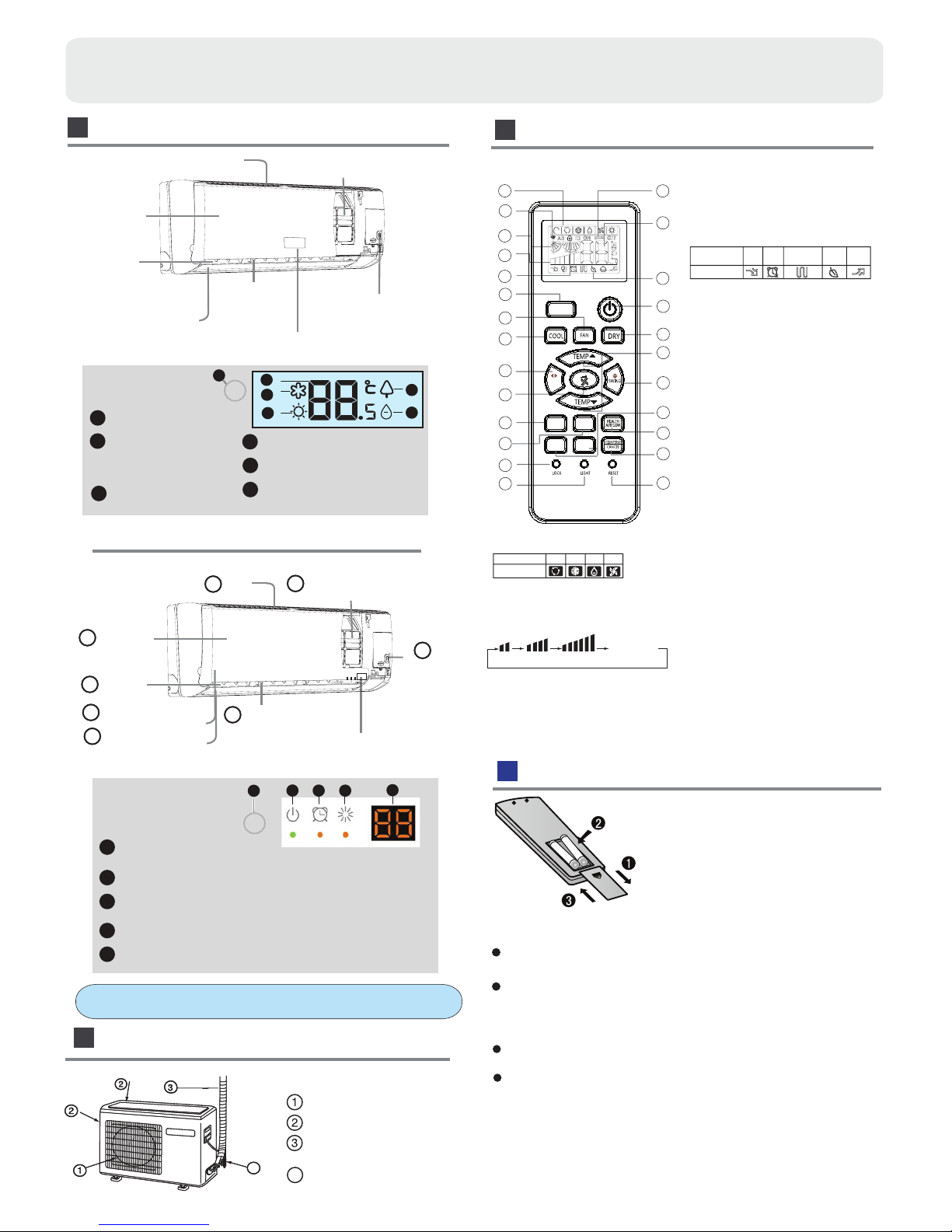
Loading of the battery
1
2
3
4
Remove the battery cover;
Load the batteries as illustrated.
2 R-03 batteries, resetting key
(cylinder);
Be sure that the loading
is in line with th
e" + "/"-";
Load the battery,then put on the cover again.
The distance between the signal transmission head and the receiver hole should be within 7m without any obstacle as well.
When electronic-started type fluorescent lamp or change- over
wireless telephone is installed in the
ver is apt to be disturbed in receiving
the signals,
so the distance to the indoor unit should be shorter.
type fluorescent lamp or
room, the recei
Note:
Full display or unclear display during operation indicates the
ries have been used up.
Please change batteries.
If the remote controller can't run normally during operation, please
reload several minutes later.
batte
remove the batteries and
TURBO
1
Parts and Functions
Remote controller
Indoor Unit
Outdoor Unit
4
OUTLET
INLET
CONNECTING PIPING
AND ELECTRICAL WIRING
DRAIN HOSE
4
Display board
(adjust left and
ow)
Vertical blade
r
ight air fl
Air Purifying Filter
Inlet
(inside)
Emergency
Switch
Horizontal flap
(adjust up and down air flow
Don't adjust it manually)
Outlet
Inlet grille
Display board
Display board
Signal receiver hole
COOL display
HEALTH display
4
2
3
1
5
DRY display
6
Ambient temp.display
When receiving the remote
control signal, display the set
temperature.
Actual inlet grille may vary from the one shown in the
manual according to the product purchased
(adjust left and
ow)
Vertical blade
r
ight air fl
Air Purifying Filter
Inlet
(inside)
Emergency
Switch
Horizontal flap
(adjust up and down air flow
Don't adjust it manually)
Outlet
Inlet grille
6
5
2
1
4
3
6
4
2
1
5
3
(inside)
7
8
Anion generator
2
3
5
6
4
HEAT display
Display board
1
4
2
3
1
5
Operation mode indicator
(lights up when the compressor is on.)
Timer mode indicator
(Lights up whenTimer operation is selected.)
Power indicator
(Lights up when unit starts.)
Ambient temp display
When receiving the remote control signal, display the set temperature.
Remote signal receiver
(A beeping sound is generated when a signal from remote controller isreceived.)
1
2
3
4
5
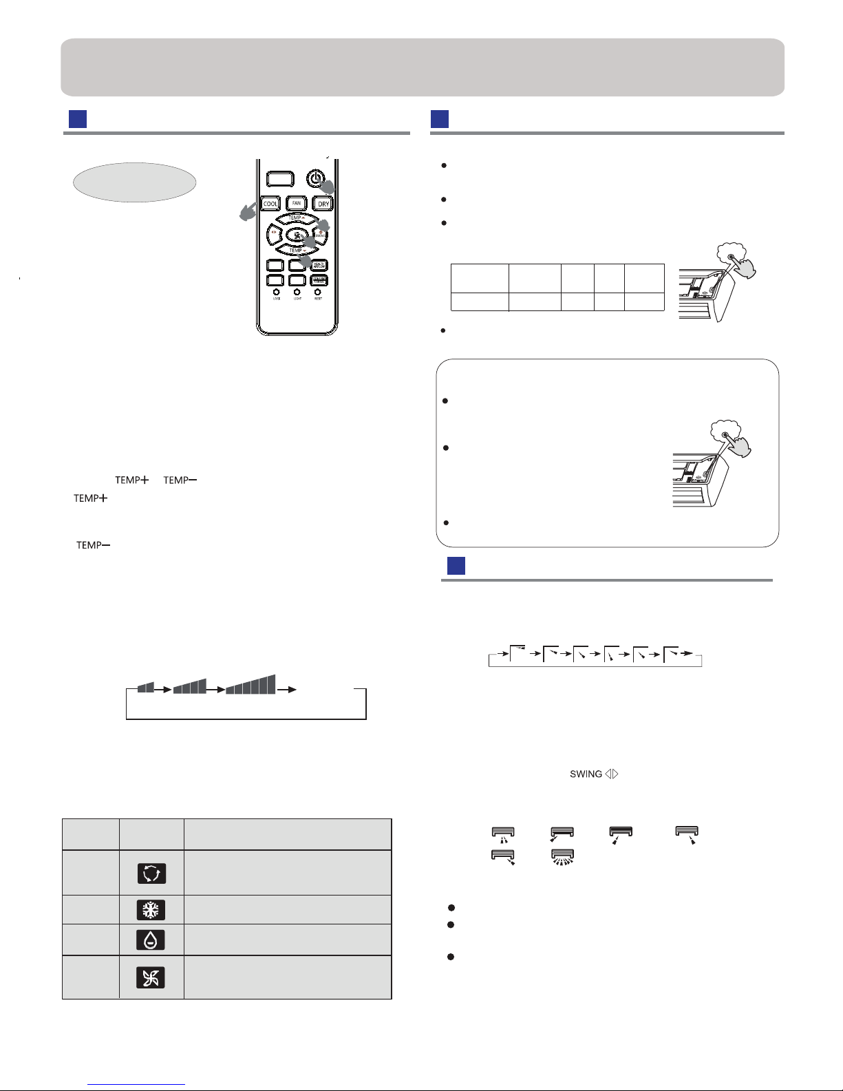
Operation
Air Flow Direction Adjustment
Base Operation
Remote controller
Emergency operation and test operation
Emergency Operation:
Use this operation only when the remote controller is defective
or lost, and with function of emergency running, air conditoner
can run automatically for a while.
When the emergency operation switch is pressed, the " Pi "
sound is heard once, which means the start of this operation.
When power switch is turning on for the first time and
emergency operation starts, the unit will run automatically in
the following modes:
It is impossible to change the settings of temp. and fan speed,It
is also not possible to operate in timer or dry mode.
Pi
1
TURBO
/QUIET
HEALTH
SLEEP
TIMER
OFF
TIMER
ON
SWING
1
2
2
Press FAN button. For each press, fan speed
follows:
Remote controller:
Press
button
Every time the button is pressed, temp.setting
increase 1
o
C,if kept depressed, it will increase
rapidly
Every time the button is pressed, temp.setting
decrease 1
o
C,if kept depressed, it will
decrease rapidly
Select a desired temperature.
4.Fan speed selection
3.Select temp.setting
Air conditioner is running under displayed fan speed.
When FAN is set to AUTO, the air conditioner
automatically adjusts the fan speed according to room
temperature.
1. Unit start
Press ON/OFF on the remote controller, unit starts.
/
2. Select operation mode
COOL button:Cooling mode
FAN button: Faning mode
DRY button: Dehumidify mode
Display
circulated
changes as
LOW
MED HI
AUTO
Remote
Controller
Note
In DRY mode , when room temperature becomes lower
than temp.setting+2
o
C, unit will run intermittently at LOW
speed regardless of FAN setting.
Under the mode of auto operation, air conditioner will
automatically select Cool or Heat operation according to
room temperature. When FAN is set to AUTO the air
conditioner automatically adjusts the fan speed according
to room temperature.
In FAN operation mode , the unit will not operate in COOL or
HEAT mode but only in
FAN mode, AUTO is not available in
FAN mode. And temp. setting is disabled. In FAN mode,
sleep operation is not available.
Operation
Mode
DRY
COOL
AUTO
FAN
3
3
4
temperature.
according to room
temperature is below 16
o
C, do not use it in the
Test operation:
Use this switch in the test operation when the room
normal operation.
your finger from the switch: the cooling
Continue to press the test operation
switch for more than 5 seconds . After
you hear the "Pi" sound twice,
release
Test ope ratio n switch is the same as emergency switch.
operation starts with the air flow speed "Hi".
Under this operation mode,the fan motor of indoor
unit will run in high speed.
Pi Pi
Room
temperature
Designated
temperature
Timer
mode
Fan
speed
Operation
mode
Above 23oC 26oC AUTO COOL
No
When restart after remote turning off, the remote controller
When adjusting the flap by hand,turn off the unit.
When humidity is high,condensate water might occur
It is advisable not to keep horizontal flap at downward
position for a long time in COOLor DRY
otherwise, condensate water might occur.
adjusted to left or at air outlet if all vertical louvers are right.
mode ,
controller will automatically memorize the previous set swing position.
Note:
Vertical flap
Pos.1
(Auto
swing)
1.Status display of air flow
2.Left and right air flow adjustment
Pos.1
Pos.2
Pos.3
Pos.4
Pos.5
Pos.6
For each press of button, remote controller
displays as follows :
remote controller:
Cautions:
Initial state
Pos.2 No initial state disaplayed on remote controller, the
vertical flap will be fixed on the current position
2
 Loading...