

Page 1
Installation Manual of Room Air Conditioner
Preparation
Necessary Tools for Installation
Torque wrench
Driverƽ
Nipperƽ
Hacksawƽ Pipe cutterƽ
Hole core drillƽ Flaring toolƽ
Spanner(17,19 and 26mm)ƽ Knifeƽ
Gas leakage detector orƽ
soap-and-water solution
ƽ
(17mm ,2 2mm, 26mm)
Measuring tapeƽ
Reamerƽ
Power Source
ƽ
Before inserting power plug into receptacle, check the voltage without fail.
The power
Install an exclusive branch circuit of the power.
ƽ
A receptacle shall be set up in a distance where the power cable can be
ƽ
reached.
source is the same as the
Donotextendthecablebycuttingit.
correspondingnameplate.
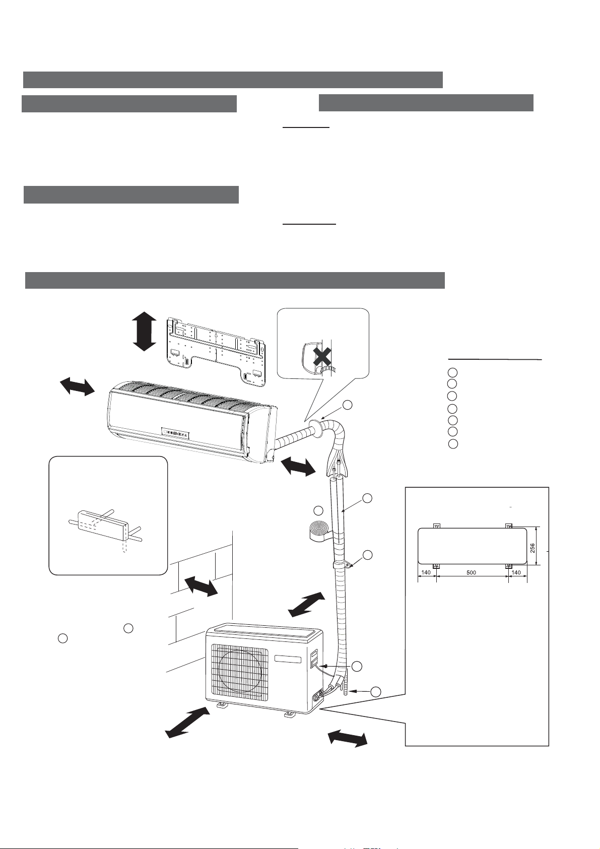
Drawing for the installation of indoor and outdoor units
ThemodelsadoptHFCfreerefrigerantR410A
more than 5cm
more than
10cm
Selection of Inastallation Place
Indoor Unit
Place, robust not causing vibration, where the body can be supported sufficiently.ƽ
Place, not affected by heat or steam generated in the vicinity, where inlet and outlet of the
ƽ
unit are not disturbed.
Place, possible to drain easily, where piping can be connected with the outdoor unit.ƽ
Place,wherecoldaircanbespreadin a roomentirely.ƽ
Place, nearby a power receptacle, with enough space around. (Refer to drawings).ƽ
Place where the distance of more than lm from televisions, radios, wireless apparatuses
ƽ
and fluorescent lamps can be left.
In the case of fixing the remote controller on a wall, place where the indoor unit can
ƽ
receivesignalswhenthefluorescent
lampsintheroomarelightened.
Outdoor Unit
Place, which is less affected by rain or direct sunlight and is suf ficiently ventilated.ƽ
Place,possibletobeartheunit,wherevibrationandnoisearenotincreased.ƽ
Place, where discharged wind and noise do not cause a nuisance to the neighbors.ƽ
Place, where a distance markedƽ
Attention must be paid to
the rising up of drain hose
is available as illustrated in the above figure.
Optional parts for piping
Non-adhesive tape
A
Adhesive tape
B
Saddle (L.S) with screws
G
C
Connecting electric cable
D
for indoor and outdoor
E
Drain hose
F
Heating insulating material
Piping hole cover
G
Arrangement of piping
directions
Left
Rear left
Rear
more than 10cm
F
A
right
Right
Below
C
more than
10cm
The marks from to
ƽ
G
in the figure are the
more than 10cm
A
parts numbers.
Thedistancebetween
ƽ
theindoorunitandthe
D
floor should be more
than 2m.
more than
60cm
E
more than15cm
Please be subject to the actual product purchased , the above picture is just for your reference.
Read this manual before installation
Explainsufficientlytheoperatingmeanstotheuseraccordingtothismanual
NO.0010531025
Floor fixing dimensions of the
outdoor unit (Unit:mm)
Fixing of outdoor unit
Fix the unit to concrete or blockƽ
withbolts(10mm)andnutsfirmly
and horizontally.
ƽ
When fitting the unit to wall
surface, roof or rooftop, fix
a supporter surely with nails
orwiresinconsideration of
earthquake and strong wind.
If vibration may affect the
ƽ
house, fix the unit by attaching a
vibration-proof mat.
Page 2
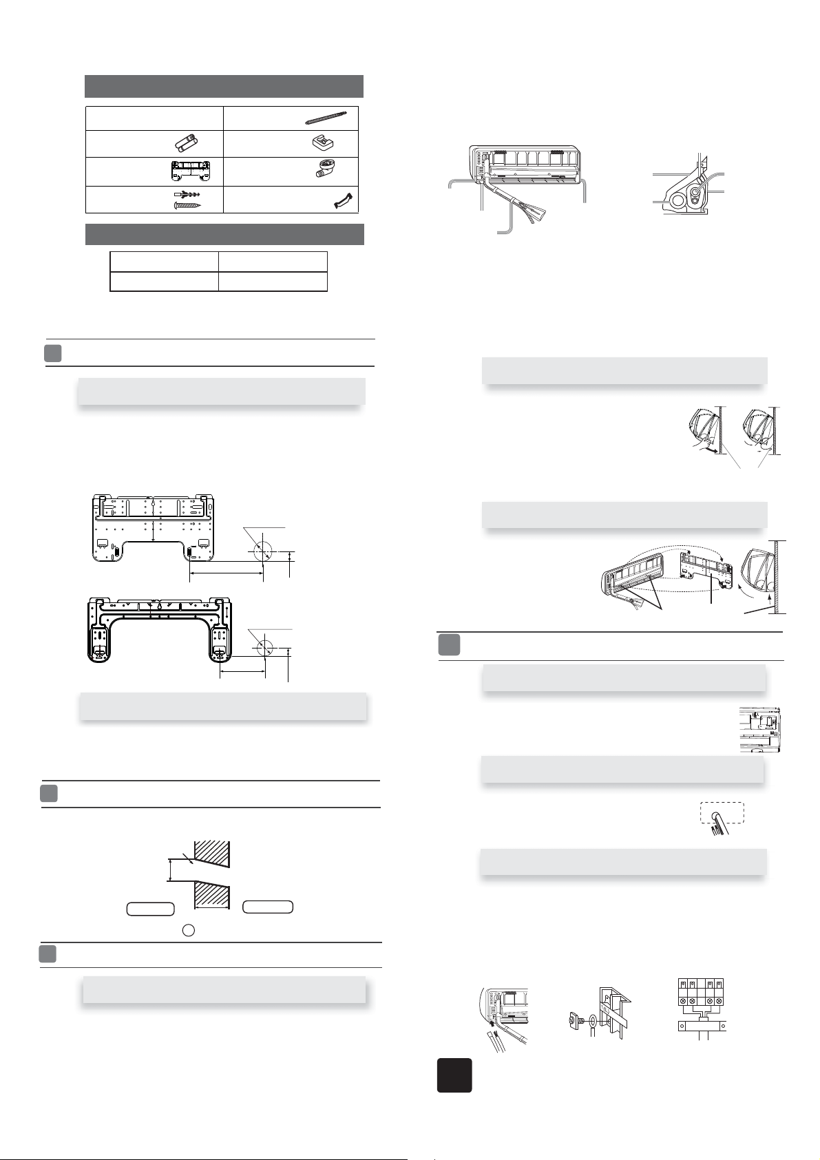
Accessory parts
Remote controller (1)
R-03 dry battery (2)
Mounting plate (1)
Plastic cap (4)
Ø4X25 Screw
(4)
Drain hose (1)
Cushion (4)
Drain-elbow (1)
Pipe supporting plate (1)
Selection of pipe
Liquid pipe (Ø) 6.35mm(1/4”)
Gas pipe (Ø) 9.52mm(3/8”)
NOTE˖Thethickness of thepipemustbe0.8mm at least.
Indoor unit
Fitting of the Mounting Plate and
When the mounting plate is first fixed
1.Carryout,basedontheneighboringpillarsorlintels, a
to be fixed against the wall, then
2. Make sure once more the proper level of the plate, by
weight from the central top of the plate, then fasten securely the plate with the
attachment steel nail.
3. Find the wall hole location A using a measuring tape
temporarily fasten the plate with one steel nail.
Positioning of the wall Hole
proper leveling for the plate
hanging a thread with a
1. Insert the drain hose into the dent of heat insulation
2. Insert the indoor/outdoor electric cable from backside of
outonthefrontside,thenconnect them.
3.Coattheflaringsealfacewithrefrigerantoilandconnect
Cover the connection part with heat insulation materials closely, and make sure
fixingwithadhesivetape
Lid for right
piping
Lid for under piping pipe
Fix with adhesive tape
ƽ
Indoor/outdoor electric cable and drain hose must be bound with refrigerant
piping by protecting tape.
Lid for left piping
materials of indoor unit.
Heat insulation
material
Drain hose
indoor unit, and pull it
pipes.
Indoor/outdoor electric cable
Piping
Pipe supporting
plate
[ Other direction piping ]
ƽ
Cut away, with a nipper, the lid for piping according to the piping direction and
then bend the pipe according to theposition of wall hole. When bending, be
careful not to crash
ƽ
Connect beforehand the indoor/outdoor electric cable,
connected to the heat insulation of connecting part specially.
pipes.
andthenpulloutthe
Fixingtheindoorunitbody
Hang surely the unit body onto the upper notches of the
ƽ
mountingplate.Movethebodyfromsidetosidetoverifyits
secure fixing.
Inordertofixthebodyontothemountingplate,holdup
ƽ
the body aslant from the underside and then put it down
perpendicularly.
mounting plate
Ø
60mm
B=
A=145mm
30mm
Ø
60mm
B=
A=145mm
30mm
When the mounting plate is fixed side bar and lintel
Fixtosidebarandlintel a mountingbar,Whichisseparatelysold,andthen
ƽ
fasten the plate to the fixed mounting bar.
Refer to the previous article, “ When the mounting plate is
ƽ
position of wall hole.
Making a Hole on the Wall and Fitting the Piping Hole Cover
Make a hole of 60 mm in diameter, slightly descending to outside the wall.
ƽ
Install piping hole cover and seal it off with putty after installation
ƽ
(Section of wall hole)
Installation of the Indoor Unit
Wall hole
Ø60mm
Indoor side
Thickness of wall
Piping hole pipe
G
Outdoor side
first fixed “, for the
Unloading of indoor unit body
When you unload the indoor unit,please use
ƽ
your hand to arise the body to leave agraffe,
then lift the bottom of the body outward
slightly and lift the unit aslant until it
leaves the mounting plate.
agraffe
Connecting the indoor/outdoor Electric Cable
Removingthewiringcover
Remove terminal cover at right bottom corner of indoor unit, then takeƽ
offwiringcoverbyremovingitsscrews.
When connecting the cable after installing the indoor unit
1. Insert from outside the room cable into left side of the wall
hole,inwhichthepipehasalreadyexisted.
2.Pulloutthecableonthefrontside,andconnectthecable
making a loop.
When connecting the cable before installing the indoor unit
Insert the cable from the backƽ
Loosen the screws and insert
ƽ
tighten the screws.
Pull the cable slightly to
ƽ
tightened.
After the cable connection,
ƽ
wiring cover.
side of the unit, then pull it out
thecableendsfullyinto
make sure the cables have
neverfailtofastentheconnectedcablewiththe
been properly inserted and
mounting plate
on the front side.
terminal block, then
[ Rear piping ]
Drawpipesandthedrainhose,thenfastenthemwiththeadhesivetape
ƽ
[Left・Left-rear piping ]
ƽ
In case of left side piping, cut away, with a nipper, the lid for left piping.
In case of left-rear piping, bend the pipes according to the piping direction to
ƽ
themark of holeforleft-rearpipingwhichismarkedonheatinsulationmaterials.
2
Drawing of pipe
When connecting the cable, confirm the terminal number of indoor and
Note
outdoor units carefully. If wiring is not correct, proper operation can not
be carried out and will cause defect.
Page 3
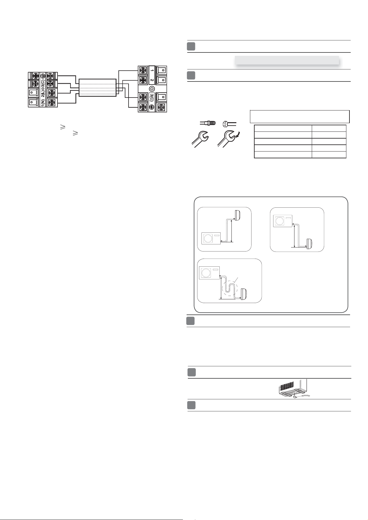
Outdoor unit
Installation of Outdoor Unit
Indoor unit
r
Powe
cable
Connecting
wiring :
HSU-09RR103/R2(SDB)
HSU-12RR103/R2(SDB)
3G1.5mm
2
4 G1.5mm
Outdoor unit
2
1.Ifthesupplycordisdamaged,itmustbereplacedbythemanufacturerorits
service agent or a similar qualified person. The type of connecting wire is
H05RN-F
2.IfthefuseonPCboardisbrokenpleasechangeitwiththe
or H07RN-F.
type of
T. 3.15 A/2 50 V.
3.Thewiringmethodshouldbeinlinewiththelocalwiringstandard.
4. After installation, the power plug should be easily reached.
5. A breakershouldbeincorporatedintofixedwiring.Thebreakershouldbe
all-pole
switchandthedistancebetweenitstwocontactsshouldbenotless
than 3mm.
Install according to Drawing for the installation of indoor and
Connection of pipes
ƽ
To bend a pipe, give the roundness as large as possible not to crush the pipe ,
andthebendingradiusshouldbe30to40
ƽ
Connecting the pipe of gas side first makes working easier.
The connection pipe is specialized for R410A.ƽ
Half union
Spanner
Becarefulthatmatters,suchaswastesofsands,etc.shallnotenterthepipe.
Thestandardpipelengthis5m.Ifitisover10m,thefunctionoftheunitwillbe
affected. If the pipe has
accordingto20g/m.Butthechargeofrefrigerantmust
sional air conditioner engineer. Before adding additional refrigerant, perform air
purgingfromtherefrigerantpipesandindoorunitusing a vacuum
charge additional refrigerant.
Flare nut
Tor qu e w ren ch
Forced fastening without careful centering may
damage the threads and cause a leakage of gas.
Liquid side6.35mm(1/4") 18N.m
Liquid/Gas side9.52mm(3/8") 42 N.m
Gas side 12.7mm(1/2") 55N.m
Gas side 15.88mm(5/8") 60 N.m
to be lengthened, the refrigerant should be charged,
mm or longer.
Pipe Diameter(ǿ) Fastening torque
outdoor units
be conducted by profes-
pump,then
CAUTION
Outdoor unit
Indoor unit
Outdoor unit
Outdoor unit
B
A
Max.Elevation: Amax=10m
●
In case the elevation A is more●
than 5m, oil trap shoud be
Oil trap
B
A
Indoor unit
installed every 5~7m
Max. Length: Bmax=15m
●
Incasethepipelength B is●
more than 10m, the refrigerant
should be charged, according
to 20 g/m.
B
Indoor unit
A
Connection
Use the same method on indoor unit. Loosen the screws onƽ
insert the plugs fully into terminal block, then tighten the screws.
ƽ
Insertthecableaccordingto terminalnumberinthesamemannerastheindoor
unit.
If wiring is not correct, proper operation can not be carried out and controller
ƽ
may be damaged.
Fix the cable with a clamp.ƽ
Attaching Drain-Elbow
If the drain-elbow is used,ƽ
please attach it as figure. (Note:
Only for heat pump unit.)
Purging Method:To use vacuum pump
1.
Detach the service port ’s cap of
and3-way’s,connecttheserviceportintothe
3-wayvalve,thevalverod’scapfor2-wayvalve
projection of charge hose (Iow)
terminal block and
3
Page 4
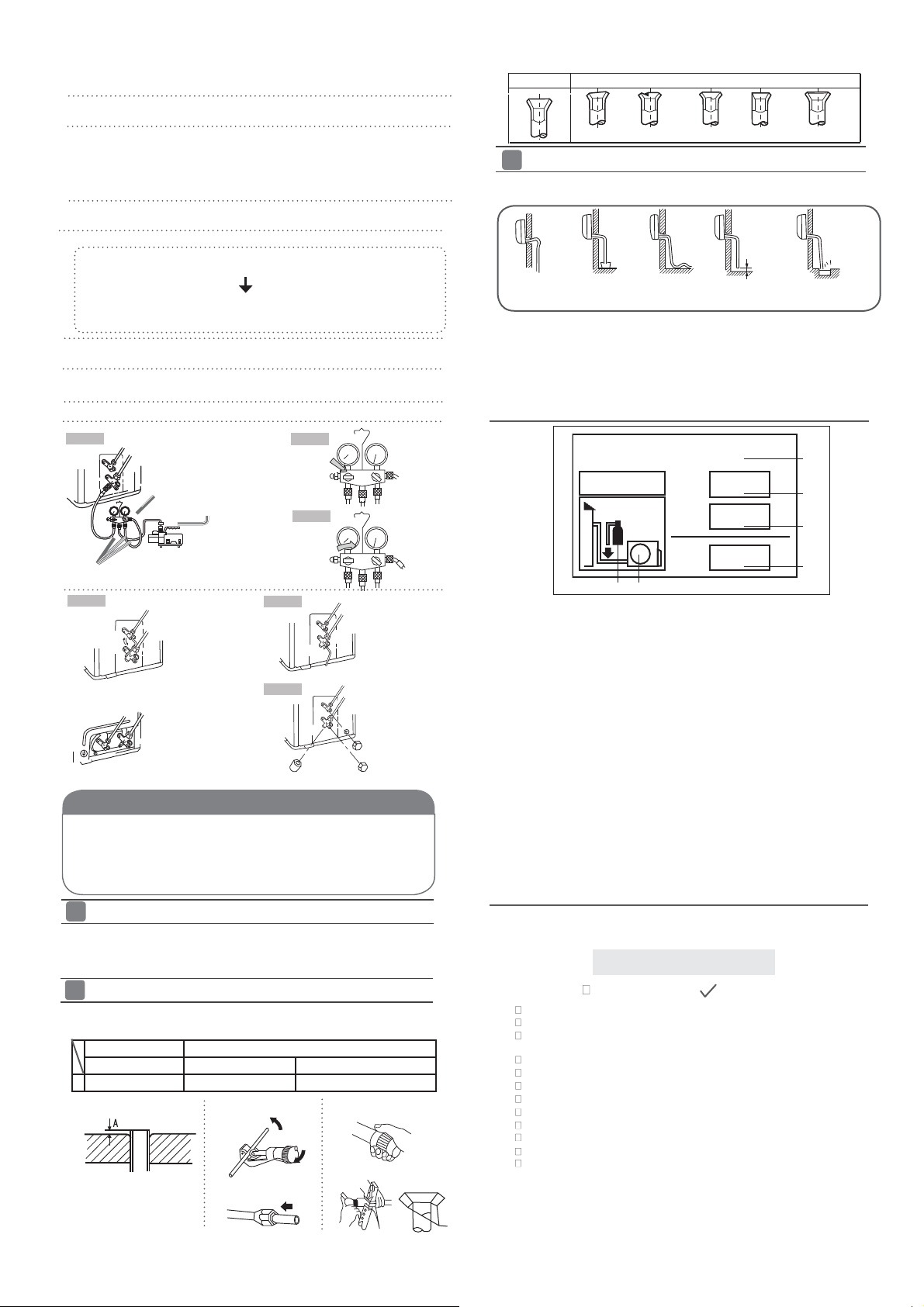
for gaugemanifold.
gemanifold
Open the handle at Iow in
2.
moves of gause (Iow) reach vacuum condition in a moment, check 1. again.
Vacuumize for over 15min.And check the level gauge which should read -0.1MPa
3.
(76 cm Hg) at Iow
handle ‘Lo’ in gaugemanifold and stop the operation of the vacuum pump. Check
conditionofthescaleandholditfor1- min.Ifthescale-movesbackinspite of
tightening, make flaring work again, the return to the beginning of 3 .
Openthevalverodforthe2-wayvalvetoanangle of4.
After 6 seconds, close the
5.
No gas leakage?
In case of gas leakage, tighten parts of pipe connection. If
If it does not stop gas leakage, discharge whole refrigerants
port. After flaring work again and vacuumize, fill up prescribed
Detach the charge hose6.
thevalverodanticlockwise untilhittinglightly.
To prevent the gas
7.
valve and 3-way’s a little more
After attaching the each
8.
Then connect
into vacuum pump.
pressure side. After the
leakagestops,thenproceed6.steps
refrigerant from the gas cylinder.
from the service port,
leakage, turn the service
caps, check the gas
the projection of charge hose (center) for gau-
gaugemanifold, operate
2-wayvalveandmakethe
than the point where the torque increases suddenly.
vacuum pump. If the scale-
completion of vacuumizing, close the
anticlockwise 90 degrees.
inspection of gas leakage.
from the service
open 2-way valve and 3-way. Turn
port’s cap, the valve
leakage around the caps.
rod’scapfor2-way
Correct Incorrect
Lean
Damage of flare Crack Partial Too outside
On Drainage
Pleaseinstallthedrainhosesoastobedownwardslopewithoutfail.
ƽ
Pleasedon’tdothedrainageasshownbelow.
ƽ
Less than
5cm
It becomes
high midway.
Please pour water in the drain pan of the indoor unit, and
ƽ
is carried out surely to outdoor.
In case that the attached drain hose is in a room, please
ƽ
it without fail.
The end is immersedinwater.
It waves.
The gap with the
ground is too small.
confirm that drainage
apply heat insulation to
Refrigerant charge labelƵ
There is the bad
smell from a ditch
Step 1.
Tube(for R410A)
Step 4.
O
Open 90
2-way valve
2-way valve Liquid Side
3-way valve Gas Side
Gaugemanifold(for
Anti countercurrent joint
Vacuum pump(for R410A)
2-way valve
3-way valve
3-way valve
R410A)
Step 2.
Open
Step 3.
Close
Step 6.
Step 7.
Service port cap
2-way valve
3-way valve
2-way valve
3-way valve
Valve rod c ap
Valve rod c ap
CAUTION
ƽ
If the refrigerant of the air conditioner leaks, it is necessar y to discharge all the
refrigerant. Vacuumize first, then
neraccordingtotheamountmarkedonthenameplate.
ƽ
Please do not let other cooling medium, except specified one (R410A), or air
enter into the cooling circulation system. Otherwise, there will be abnormal
highpressureinthesystemtomakeitcrackandleadtopersonalinjuries.
Power Source Installation
ƽ
The power source must be exclusively used for air
ƽ
In the case of installing an air conditioner in a moist place,
rth leakage breaker.
ƽ
For installation in other places, use a circuit breaker as far
Cutting and Flaring Work of Piping
ƽ
Pipecuttingiscarriedoutwith a pipecutterandbursmust
ƽ
Afterinsertingtheflarenut,flaring workiscarriedout.
FlaretoolforR410A Conventionalflaretool
Clutch-type clutch-type(Rigid-type) Wing-nut type (Imperial-type)
A 0 ~0.5mm 1.0~1.5mm 1.5~2 .0mm
Flare tooling die
chargetheliquidrefrigerantintoairconditio-
conditioner. (Over I0A)
please install an ea-
as possible.
be removed.
1.Cut pi pe
3.Inserttheflarenut
2.Remove burs
4.Flare pipe
Contains fluorinated greenhouse gases
covered by the Kyoto Protocol
R410A
2
1=
2=
1
1+2=
FE
kg
kg
kg
A
B
C
D
This product contains fluorinated greenhouse gases covered by
the Kyoto Protocol. Do not vent into the atmosphere.
Refrigerant type:R410A
GWP* value:1975
GWP=global warming potential
Please fill in with indelible ink,
• 1 the factory refrigerant charge of the product
• 2 the additional refrigerant amount charged in the field and
• 1+2 the total refrigerant charge
on the refrigerant charge label supplied with the product.
The filled out label must be adhered in the proximity of the product
charging port (e.g. onto the inside of the stop value cover).
A contains fluorinated greenhouse gases covered by the Kyoto
Protocol
B factory refrigerant charge of the product: see unit name plate
C additional refrigerant amount charged in the field
D total refrigerant charge
E outdoor unit
F refrigerant cylinder and manifold for charging
Check for Installation and Test Run
Ƶ
Please kindly explain to our customers how to operate
Ƶ
throughtheinstructionmanual.
Check Items for Test Run
Put check mark
Gasleakfrompipeconnecting?
Heat insulation of pipe connecting?
Are the connecting wirings of indoor and outdoor firmly
inserted to the terminal block?
Is the connecting wiring of indoor and outdoor firmly fixed?
Is drainage securely carried out?
Is the earth line securely connected?
Istheindoorunitsecurelyfixed?
Is power source voltage abided by the code?
Is there any noise?
Isthelampnormallylighting?
Arecoolingandheating(wheninheatpump)performednormally?
Is the operation of room temperature regulator normal?
in boxes
4
 Loading...