

Haier HSU-12HD03R2 Schematic

Air Conditioner
REVISION 0
CAUTION
READ THIS MANUAL CAREFULLY TO
DIAGNOSE TROUBLE CORRECTLY
BEFORE OFFERING SERVICE .
SERVICE MANUAL
Edition:2006/1/10
Air Conditioners
THIS MANUAL IS USED BY
QUALIFIED APPLIANCE
TECHNICIANS ONLY. HAIER
DOES NOT ASSUME ANY
RESPONSIBILITY FOR PROPERTY
DAMAGE OR PERSONAL INJURY
FOR IMPROPER SERVICE
PROCEDURES DONE BY ONE
UNQUALIFIED PERSON.
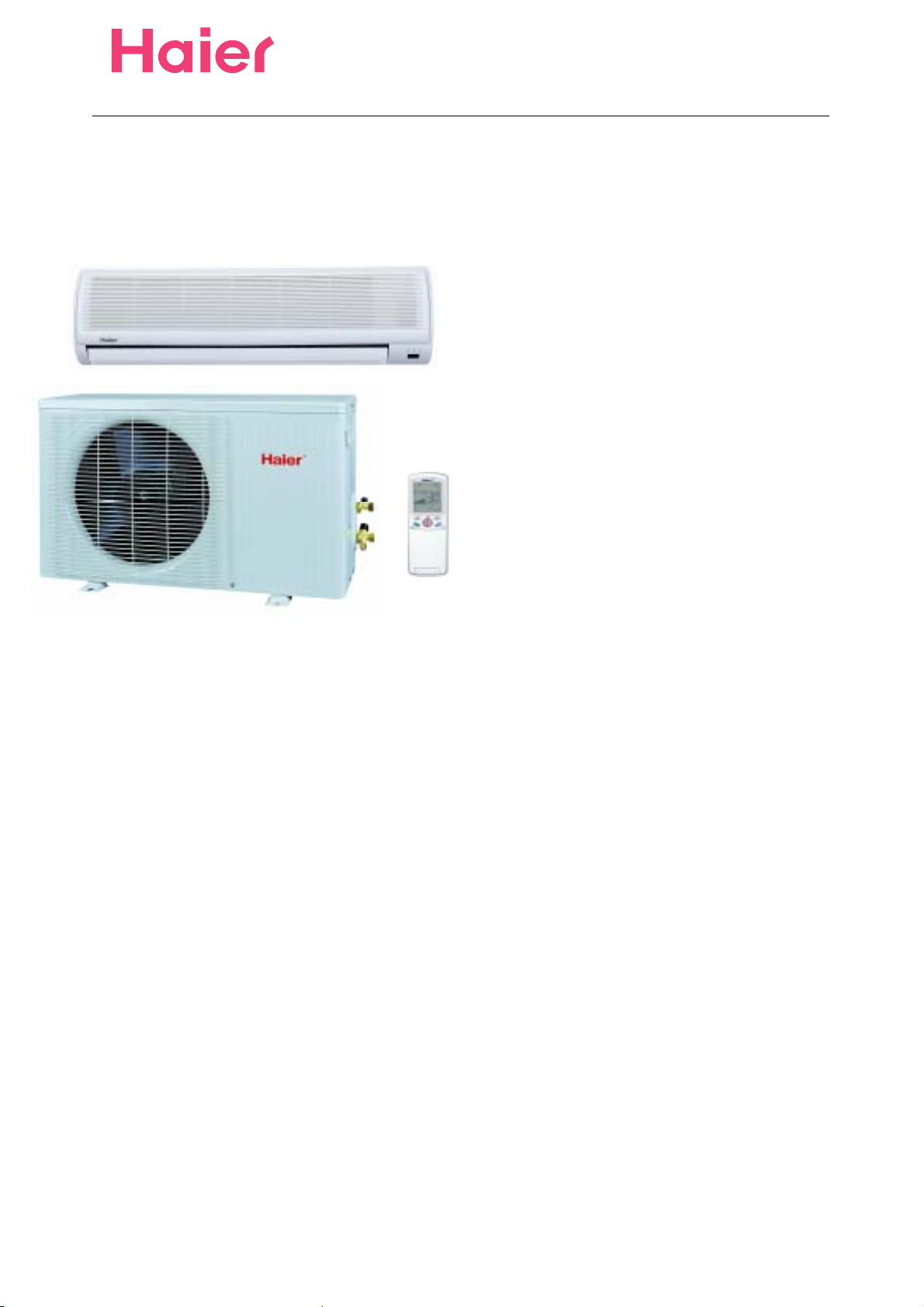
MODEL: HSU-MODEL: HSU-12HD03/R2
Air Conditioner
Edition:2006/1/10Air Conditioner
Edition:2006/1/10Air Conditioner
Edition:2006/1/10
IMPORTANT INFORMATION
MODEL: HSU-12HD03/R2
ƽҏFeatures
ƽҏComfortable: wide-angle airflow
ƽhealth air purifying
ƽquiet operation
ƽҏsuper energy efficient
ƽMain Specification
ƽCooling CapacityΚ 3500W
ƽRated Power/Current(cooling)Κ 1090W/5.2A
ƽEER: 3.21
ƽHeating CapacityΚ 3650W
ƽRated Power/Current(heating): 1010W/5.0A
ƽCOP: 3.61
3
ƽAir Volume(Indoor): 500m
ƽPower: 1PH 220-230V~ 50 Hz
/h
Air Conditioner
Edition:2006/1/10
Safety Information
General Information
This Service Manual describes the operation,disassembly,troubleshooting,and repair of Haier Room Air
Conditioners,etc. It is intended for use by authorized servicers who troubleshoot and repair these units.
NOTE:It is assumed that users of this manual are familiar with the use of tools and equipment used to
troubleshoot and repair electrical,mechanical,and refrigeration systems;and understand the terminology
used to describe and discuss them.
Haier urges you read and follow all safety precautions and warnings contained in this manual. Failure
to comply with safety information may result in severe personal injury or death.
Related Publications
This is a base service manual,covering a range of similar models.It is intended to be used in
conjunction with the Parts Manual and Technical Sheet covering specific model being serviced.
General Precautions and Warnings
To avoid risk of personal injury or death due to electrical shock,disconnect electrical power to unit
before attempting to service the unit.
WARNING
WARNING
To avoid risk of personal injury or death due to electrical shock,DO NOT,under any circumstances,alter
the grounding plug .Air conditioner must be grounded at all times.Do not remove warning tag from power
cord.If a two-prong (non-grounding) wall receptacle is encountered,contact a qualified electrician and
have the receptacle replaced with a properly grounder wall receptacle in accordance with the National
Electrical Code.
To avoid risk of personal injury or death due to electrical shock,grounding wires and wires colored like
groundi ng wires are NOT to be used as current carrying conductors.The standar d accepted color c oding
for ground wires is green or green with a yellow stripe.Electrical components such as the compressor
and fan motor are grounded through an individual wire attached to the electrical component and to
another part of the air conditioner.Groundi ng wires should not to be removed from individual components
while servicing,unless the component is to be removed and replaced.It is extremely important to replace
all removed grounding wires before completing service.
WARNING
WARNING
To avoid risk of heat exposure,which may cause death or severe illness,air conditioner must be
monitored when malfunctions or shuts down.

Air ConditionerEdition:2006/1/10
CONTENTS
1.SPECIFICATION...............................................................................1
2.ACCESSORIES ................................................................................3
4.OPERATION......................................................................................
5.ELECTRI CAL CONTROLL.............................................................
6.TROUBLE SHOOTING...................................................................
7. INSTALLA TION...............................................................................
8. CIRCUIT AND WIRING DIAGRAM.............................................
42,44
5
21
28
33

Air Conditioner
Edition:2006/1/10
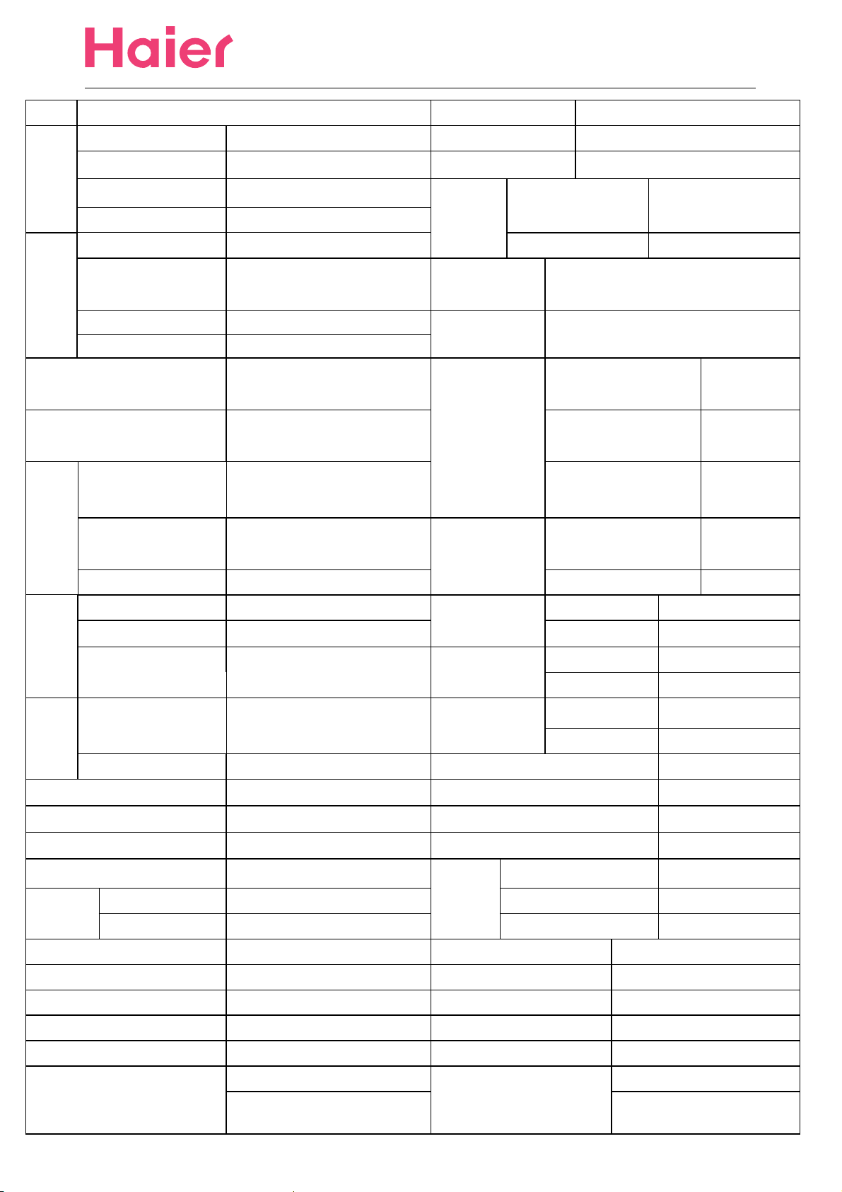
SPECIFICATION
1
8.0A
Oilcharge
Air Conditioner
SANYO/CRV113
500(poe)
Edition:2006/1/10
Model˖
Cooling
Heating
Power/Current of
Electric Heating˖
HSU-12HD03/R2
Cooling Capacity˖
Rated Power/Current˖
Max Power/Current˖
EER
Heating Capacity˖
Rated Power/Current˖
Max Power/Current˖ 1600W/
COP 3.61
3500W
1090W/5.2A
1620W/8.3A
3.21
3650W
1010W/5.0A
----- Type/Net Charge˖
Operating temp. range -7OC-43OC
1350 r/min
1100 r/min
Indoor
Velocity
H˖
M˖
Brand Mark˖
Frequency Range˖
1PH 220-230V~ 50 Hz
Power
Power Cord
Compressor
manufacturer/Type
Compressor
Refrigerant
Capilary
Model×Sectional Area˖
Refer. No.˖ --------
Additional Charge for
exhausting air.
Charge if over Standrad
Pipe Lenth
Lenth×Internal/External
Diametre
-----
50Hz
--------
R410A 800g
----- g
---g/m
-----
L˖
H˖ 1000 r/min Indoor˖ 1.30 mm
Outdoor
Velocity
Vol ume
(High)
Capacitor of Fan Motor˖
Class of electric Shock Protection
Class of Water Proof˖ IP 24 Outdoor Packaging dimension(L×W×H) 876×364×638 mm
Moisture Removal˖
Remote
Controller Refer. No.˖
Remote Controller Bracket˖ ----- Lenth/Diametre of Drain Hose 4.15 MPa
Appearance˖ ----- Max. pressure at warm side˖ 4.15 MPa
H˖ ---- r/min
H˖ ---- r/minNet˖
Air
Indoor˖ 500 m3/h
Outdoor˖ ----- m
Model˖
920 r/min
……
ĉ
-3m3
1.5×10
/h
H
0010413791
Height of rising
radiator slice
Indoor Weight
Outdoor Weight
3
/hIndoor Dimension(L×W×H)˖ 795×265×182 mm
Indoor Packaging Dimension(L×W×H) 865x272x330 mm
Outdoor Dimension (L×W×H)˖
Refrigerant
Pipe
liquid /Gas pipe Diametre
standard Lenth
Max Lenth 15 m
Refer No.˖ -----
Outdoor˖ 1.37 mm
7.6kg
Gross˖
Net˖
Gross˖
5m
10.6kg
37kg
42kg
855×331×596 mm
ij6.35/9.52 mm
Climate Type˖ T1 Max.pressure at cool side˖ ---
Installation Bracket Type˖ ----- Plug Type(spec.)˖ ---
Area available for clooling/heating
Max.running
temperature(cooling):
15-23 m
Dry/Wet ball(indoor)˖ 32℃/ 223 ćDry/Wet ball(indoor):27 /ć --ć
Dry/Wet ball(outdoor)˖ 43 / 26 ćć
2
Ammeter spec.˖ ---
Max.running
temperature(heating):
Dry/Wet ball(outdoor):24℃/18℃
2

Air Conditioner
Edition:2006/1/10
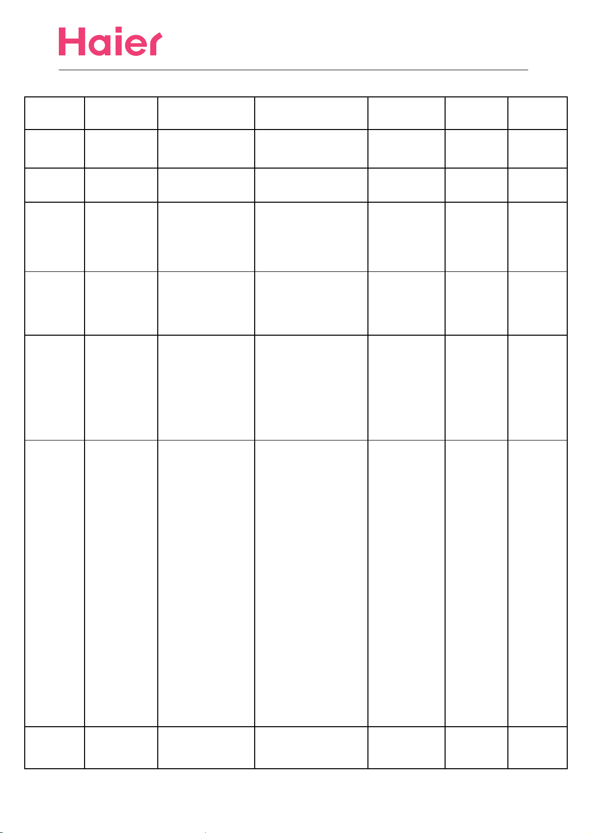
ACCESSORIES
3
Air Conditioner
HSU-12HD03/R2
Edition:2006/1/10
Number Name Refer No. Description Quality
1
2 battery 001A4600001 None 2 0.1
3
4 drain pipe 001A0900011
5
remote
controller
mounting
plate
connecting
pipe
0010413791 None 1 0.2
Fix mounting plate
0010101275
----
according to
installation position
and pipe direction
Choose the place
that can drain
water and connect
pipe easily
The maximal
length of the
connecting pipe is
15m,the maximal
height between
indoor unit and
outdoor unit is 5m
0
1 0.1
1 0.2
Failure
Remark
Rate(%)
*
*
The conecting
methods include
ring terminal and
direct
terminal .Ring
terminal
connecting
method:Unscrew
the screws ,and
6
connecting
wire
----
put it through the
ring of connecting
line ends,then
connect it into the
terminal block.
Direct terminal
connecting
method:unscrew
the screws,then
fully insert the
cable ends into.
.
1
0.2
*
7 manual 001A7265614 Operation 1 0
4

Air Conditioner
Edition:2006/1/10
OPERRATION
5
Contents
6
Air Conditioner
Edition:2006/1/10
Cautions
Parts and functions
Operation
Maintenance
Trouble shooting
1
2-4
5-12
13-14
15

Air Conditioner
Cautions
The machine is adaptive in following situation
I. Applicable ambient temperature range:
Edition:2006/1/10
Indoor
Cooling
Outdoor
Indoor
Heating
Outdoor
2. If the supply cord is damaged, it must be replaced by the manufacturer or its service agent
or a similar qualified person. The type of connecting wire is H05RN-F or H07RN-F
3. If the fuse on PC board is broken please change it with the type of T. 3.15A/250V.
4. The distance between the indoor unit and the floor should be more than 2m.
5. The wiring method should be in line with the local wiring standard.
6. After installation, the power plug should be easily reached.
7. The waste battery should be disposed properly.
8. The appliance is not intended to use by young children or infirm persons without supervision.
9.Young children should be supervised ensure that they do not play with the appliance.
10.The appliance must be installed on strong enough supporter.
11.The wiring diagram is attached inside the machine.
Maximum: D.B / W.B 32oC/23oC
Minimum: D.B / W.B
Maximum: D.B
Minimum: D.B
Maximum: D.B
Minimum: D.B
Maximum: D.B / W.B
Minimum: D.B / W.B
18oC/14oC
43oC/26oC
18oC
27oC
15oC
24oC/18oC
-7oC/-8oC
7
Air Conditioner
Parts and Functions
Edition:2006/1/10
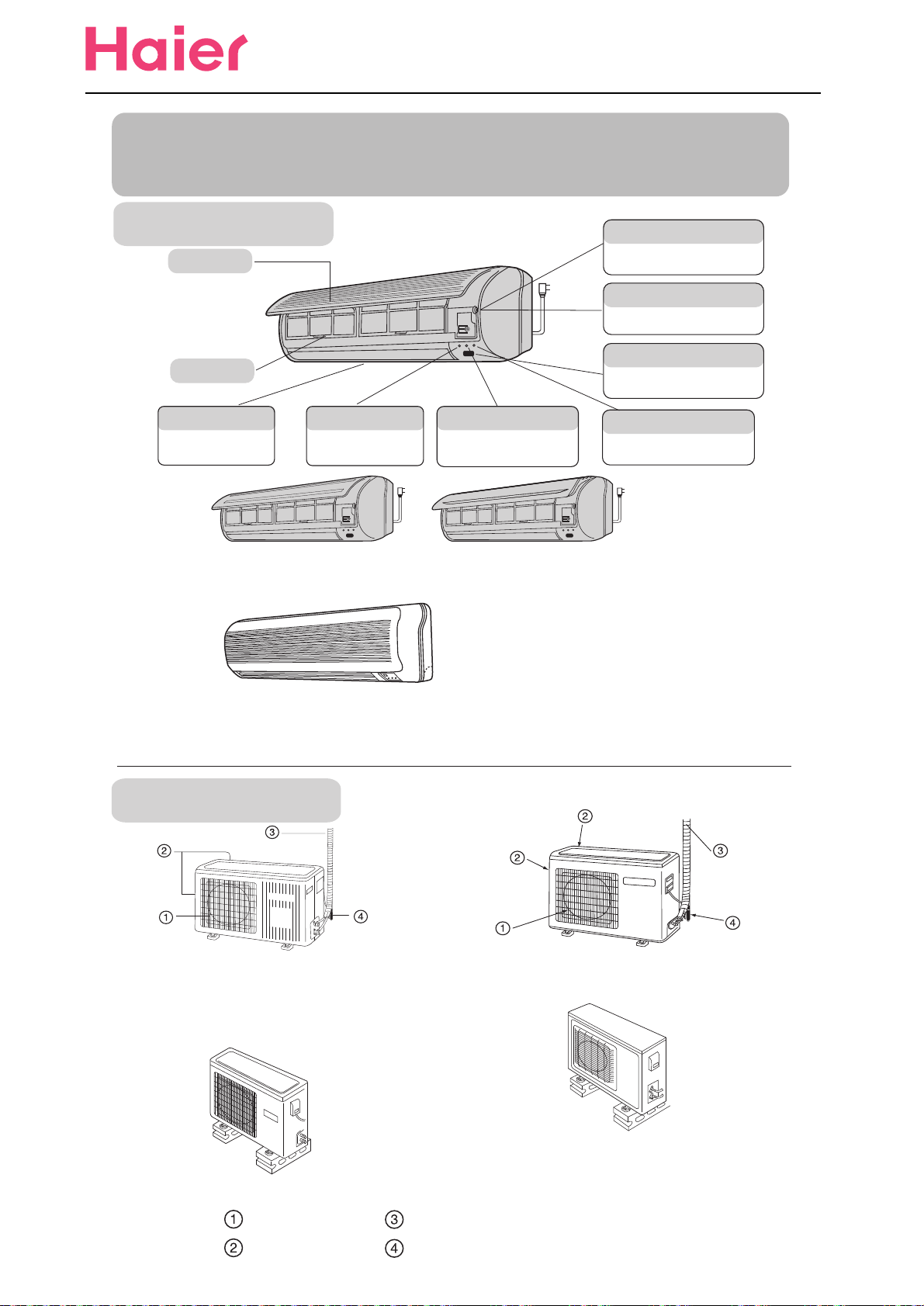
Indoor Unit
Inlet grille
Air filter
Vertical flap
Use remote controller to
adjust up and down air flow.
(Don't adjust it manually.)
HSU-07HC03/R2 HSU-07HE03/R2 HSU-09HC03/R2 HSU-09HE03/R2
HSU-12HE03/R2 HSU-12HC03/R2 HSU-14HB03/R2 HSU-18HB03/R2
Power indicator
Lights up when unit starts.
Timer mode indicator
Lights up when Timer operation
is selected.
Test running switch(manual)
Used only for test running in cooling
when room temp. is below 16oC.
Don't use it in normal operation.
Emergency switch(manual)
Used when remote controller is lost or
defective. Unit will run temporarily.
Remote signal receiver
A beeping sound is generated when
a signal from remote controller is
received.
Operation mode indicator
Lights up during compressor
running.
HSU-09HD03/R2
HSU-12HD03/R2
HSU-07HD03/R2
HSU-22HB03/R2 HSU-22HC03/R2 HSU-22HD03/R2
Actual inlet grille may vary from the one shown in the manual according to
the product purchased
Outdoor Unit
HSU-07HC03/R2
HSU-07HE03/R2
HSU-07HD03/R2
HSU-18HB03/R2
HSU-09HE03/R2
HSU-12HE03/R2
HSU-09HD03/R2
HSU-12HD03/R2HSU-09HC03/R2
HSU-12HC03/R2
HSU-14HB03/R2
HSU-22HD03/R2
HSU-22HC03/R2
HSU-22HB03/R2
OUTLET
INLET
CONNECTING PIPING AND ELECTRICAL WIRING
DRAIN HOSE
8
Air Conditioner
Parts and Functions
Edition:2006/1/10
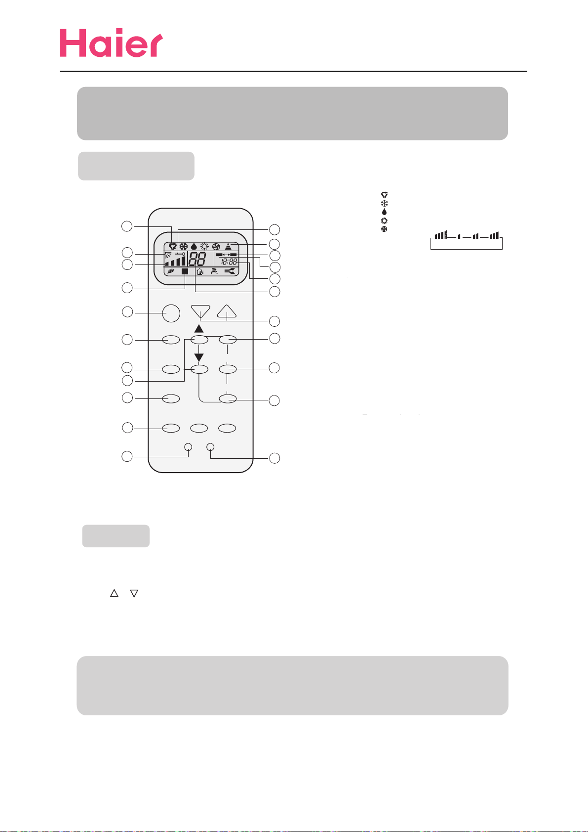
Operation
1
2
3
4
11
12
13
14
15
16
17
Clock set
ON/OFF
MODE SET
FAN
SWING
SLEEP
LOCK RESET
Buttons and display of the remote controller.
1. Mode display
AUTO
COOL
DRY
HEAT
5
6
A
U
T
O
ON OFF
7
8
9
TEMP
TIMER
CLOCK
10
18
19
20
21
22
FAN
2. SWING display
3. FAN SPEED display
4. SLEEP display
5. LOCK display
6. SIGNAL SENDING
7. TIMER OFF display
8. TIMER ON display
9. CLOCK display
10. TEMP display
11. POWER ON/OFF
Used for unit start and stop.
12. MODE
Used to select AUTO run, COOL,
DRY, HEAT and FAN operation
13. FAN
Used to select fan speed LO, MED, HI, AUTO
14. HOUR
Used to set clock and timer setting.
15. SWING
Used to set auto fan direction.
16. SLEEP
Used to select sleep mode.
17. LOCK
Used to lock buttons and LCD
display.
18. TEMP.
Used to select your desired temp.
19. SET
Used to confirm timer and clock settings.
20. TIMER
Used to select TIMER ON, TIMER OFF,
TIMER ON-OFF
21. CLOCK
Used to set correct time
22. RESET
Used to reset the controller back to
normal condition.
When unit is started for the first time and after replacing batteries in remote controller,
clock should be adjusted as follows:
Press CLOCK button, "AM" or "PM" flashes.
Press or to set correct time. Each press will increase or decrease 1min. If the
button is kept depressed, time will change quickly.
After time setting is confirmed, press SET, "AM "and "PM" stop flashing, while clock
starts working.
NOTE: Cooling only unit do not have displays and functions related with heating
LO MED HIAUTO
Hints
After replacing with new batteries, remote controller will conduct self-check, displaying
all information on LCD. Then, it will become normal.
9
Air Conditioner
Parts and Functions
Edition:2006/1/10
Operation
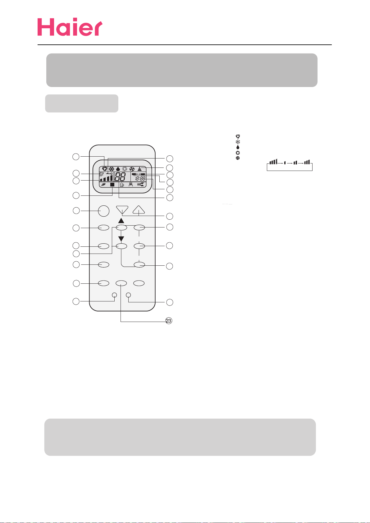
Buttons and display of the remote controller.
If the unit which you purchased has healthy function, Remote controller should
like the following figure:
1
ON
2
3
A
U
T
O
OFF
4
ON/OFF TEMP
11
MODE SET
12
13
14
15
16
17
FAN TIMER
SWING CLOCK
SLEEP
HEALTH
LOCK RESET
BRIEF INTRODUCTION TO HEALTH OPERATION
The anion generator in the air conditioner can generate a lot of anion to
effectively balance the quantity of position and anion in the air and also to kill
bacteria and speed up the dust sediment in the room and finally clean the air
in the room.
NOTE: Cooling only unit do not have displays and functions related with heating
5
6
7
8
9
10
18
19
20
21
22
1. Mode display
AUTO
COOL
DRY
HEAT
FAN
2. SWING display
3. FAN SPEED display
4. SLEEP display
5. LOCK display
6. SIGNAL SENDING
7. TIMER OFF display
8. TIMER ON display
9. CLOCK display
10. TEMP display
11. POWER ON/OFF
Used for unit start and stop.
12. MODE
Used to select AUTO run, COOL,
DRY, HEAT and FAN operation
13. FAN
Used to select fan speed LO, MED, HI, AUTO
14. HOUR
Used to set clock and timer setting.
15. SWING
Used to set auto fan direction.
16. SLEEP
Used to select sleep mode.
17. LOCK
Used to lock buttons and LCD
display.
18. TEMP.
Used to select your desired temp.
19. SET
Used to confirm timer and clock settings.
20. TIMER
Used to select TIMER ON, TIMER OFF,
TIMER ON-OFF
21. CLOCK
Used to set correct time
22. RESET
Used to reset the controller back to
normal condition.
23. HEALTH
Used to set healthy operation
AUTO
MED
LO
HI
Hints
After replacing with new batteries, remote controller will conduct self-check, displaying
all information on LCD. Then, it will become normal.
10
Air Conditioner
Operation
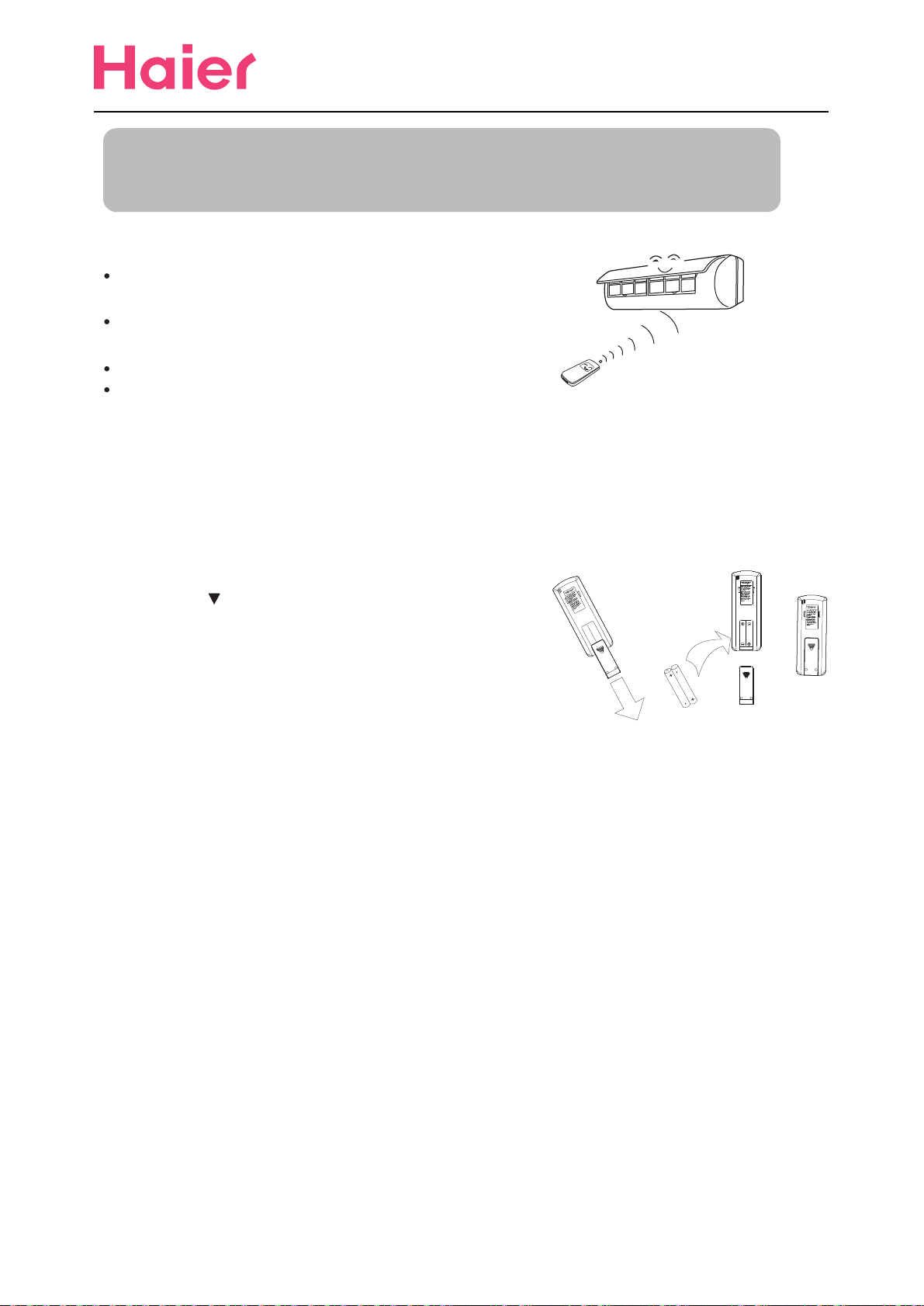
Remote controller's operation
When in use, put the signal transmission head directly to the
receiver hole on the indoor unit.
The distance between the signal transmission head and the
receiver hole should be within 7m without any obstacle as well.
Don't throw the controller, prevent it from being damaged.
When electronic-started type fluorescent lamp or change-over
type fluorescent lamp or wireless telephone is installed in the
room, the receiver is apt to be disturbed in receivering the signals
so the distance to the indoor unit should be shorter.
Loading of the battery
Edition:2006/1/10
Load the batteries as illustrated. 2 R-03 batteries, resetting key (cylinder)
Remove the battery cover:
Slightly press " " and push down the cover.
Load the battery:
Be sure that the loading is in line with the" + "/"-"
pole request as illustrated.
Put on the cover again
Confirmation indicator:
In disorderation, reload the batteries or load the new batteries after 6mins.
Note:
Use two new same-typed batteries when loading.
If the remote controller can't run normally or doesn't work at all,
use a sharp pointed item to press the reset key.
Hint:
Remove the batteries in case unit won't be in usage for a long period.
If there are any display after taking-out just need to press reset key.
Power failure resume(please set and apply as necessary)
If sudden power failure occurs, the unit will resume original operation when power is
supplied again.
Note:
When sudden power failure happens during unit operation in power failure resume mode, if
the air conditioner is not desired for use in a long period, please shut off the power supply
in case that the unit automatically resume operation when power is re-supplied, or press
ON/OFF to turn off the unit when power resumes.
11
Operation
Air Conditioner
Edition:2006/1/10
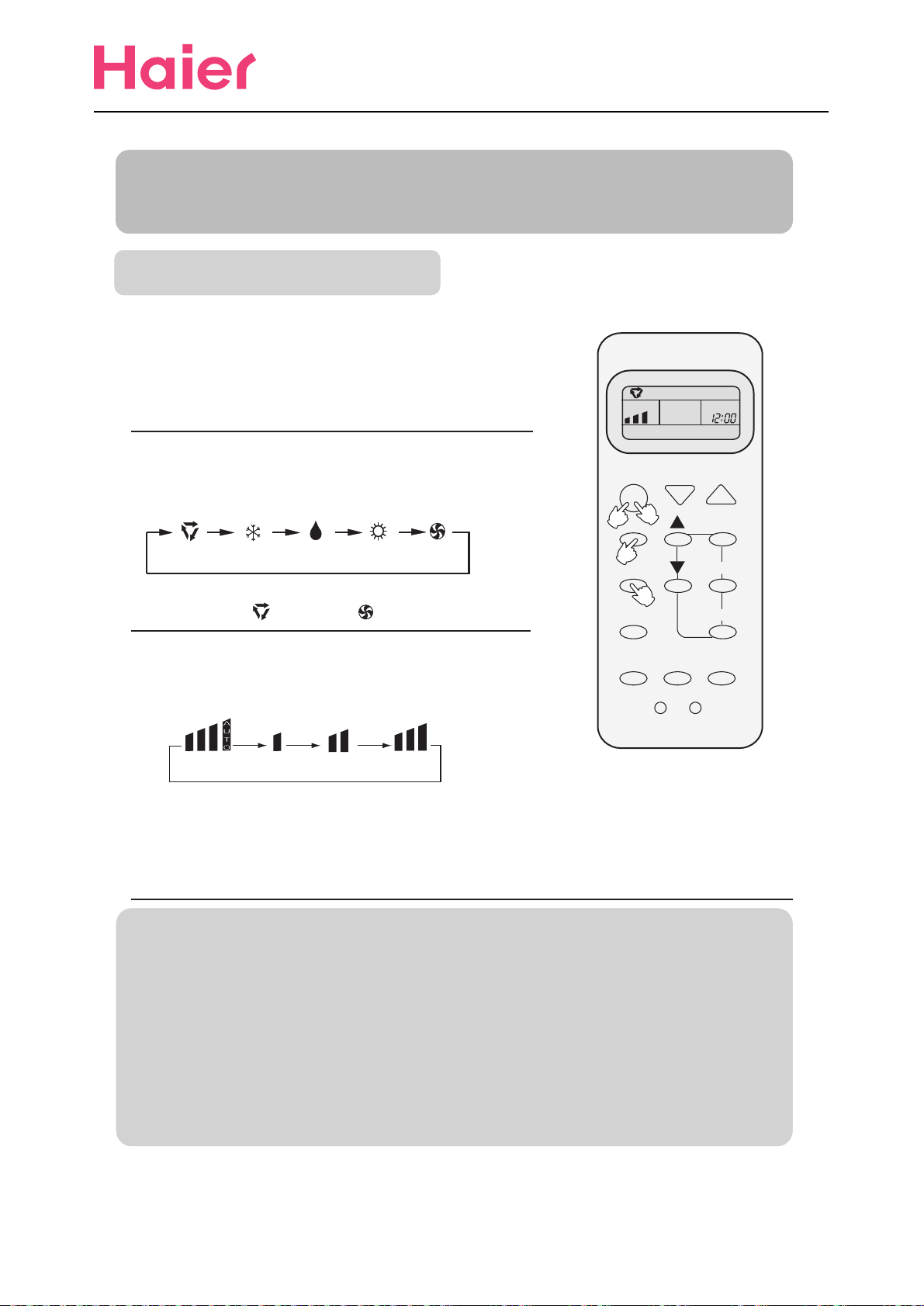
Auto run, Fan operation
Enjoy yourself by just a gentle press.
(1) Unit start
Press ON/OFF button, unit starts.
Previous operation status appears on display.
(Not Timer setting)
Power indicator on indoor unit lights up.
(2) Select operation mode
Press MODE button. For each press, operation
mode changes as follows:
AUTO COOL DRY HEAT FAN
Unit will run in selected mode.
Stop display at " " AUTO or " "FAN.
(3) FAN
Press FAN button. For each press, fan speed changes
as follows:
ON/OFF TEMP
1
4
MODE
2
FAN
3
CLOCKSWING
SLEEP
LOCK
SET
TIMER
RESET
AUTO LO MED HI
(4) Unit stop
Unit will run at selected fan speed.
Note:AUTO is not available in FAN mode.
Press ON/OFF button.
Only time remains on LCD.
All indicators on indoor unit go out.
Vertical flap closed automatically.
Hints
Remote controller can memorize settings in each operation mode. To run it next time just
select the operation mode and it will start with the previous setting.
No reelecting is needed.(TIMER ON/OFF needs reelecting)
Cautions: Note:
On cooling only unit, heating mode is not available, The above information is the
After replacing batteries, press ON/OFF, and display explanation of the displayed
becomes as follows: information therefore varies
Operation mode: AUTO, Temp. No with those displayed in actual
Timer mode: No, Fan speed :AUTO operation.
12
 Loading...