

Haier HSU-10HA03-DB User Manual

SPLIT AIR CONDITIONER
OPERATION
MANUAL
AS102AMARA
AU102ACARA
(HSU-10HA03(DB))
AS102ALARA
AU102ACARA
(HSU-10H03(DB))
AS122AYARA
AU122ACARA
(HSU-12HA03(DB))
AS122AVARA
AU122ACARA
(HSU-12H03(DB))
Digital DC Variable Frequency
Healthy Split Air Conditioner
Please read this manual carefully before use.
Please keep this manual carefully and safely.
No.0010540438
I

Contents
Cautions........................................................................................................1-2
Name of Parts...............................................................................................3-4
Operation Hints............................................................................................5-6
Operation.....................................................................................................7-13
Notes for Safety.........................................................................................14-15
Maintenance............................................................................................. 16-18
Trouble Shooting.......................................................................................19-21
Installation.................................................................................................22-30
Installation Check and Trial Operation...........................................................31

Cautions
Disposal of the old air conditioner
Before disposing an old air conditioner that
goes out of use. please make sure it's
inoperative and safe. Unplug the air
conditioner in order to avoid the risk of child
entrapment.
It must be noticed that air conditioner system
contains refrigerants, which require
specialized waste disposal. The valuable
materials contained in a air conditioner can
be recycled. Contact your local waste
disposal center for proper disposal of an old
air conditioner and contact your local
authority or your dealer if you have any
question. Please ensure that the pipework of
your air conditioner does not get damaged
prior to being picked up by the relevant
waste disposal center, and contribute to
environmental awareness by insisting on an
appropriate, anti-pollution method of
disposal.
All these valuable materials may be taken to
a waste collecting center and used again
after adequate recycling.
Consult your local authorities for the name
and address of the waste materials
collecting centers and waste paper diposal
services nearest to your house.
Safety Instructions and Warnings
Before starting the air conditioner,read the
information given in the User's Guide
carefully. The user's Guide contains very
important observations relating to the
assembly, operation and maintenance of
the air conditioner.
The manufacturer does not accept
responsibility for any damages that may
airse due to non-observation of the
following instruction.
Damaged air conditioners are not to be
put into operation.In case of doubt,consult
your supplier.
Disposal of the packaging of your
new air conditioner
All the packaging materials employed in the
package of your new conditioner may be
disposed without any danger to the
environment.
The cardboard box may be broken or cut into
smaller pieces and given to a waste paper
diposal service. The wrapping bag made of
polyethylene and the polyethylene foam
pads contain no fluorochloric hydrocarbon.
Use of the air conditioner is to be carried
out in strict compliance with the relavtive
instructions set forth in the User's Guide.
Installation shall be done by professional
people,don't install unit by yourself.
1
Cautions
3
For the purpose of safety, the air
conditioner must be properly grounded in
accordance with specifications.
Always remember to unplug air
conditioner before opening inlet grill. Never
unplug your air conditioner by pulling on the
power cord.Always grip plug firmly and pull
straight out from the outlet.
All electrical repairs must be carried out
by qualified electricians. Inadequate repairs
may result in a major source of danger for
the user of the air conditioner.
Do not damage any parts of the air
conditioner that carry refrigerant by piercing
or perforating the air conditioner's tubes with
sharp or pointed items, crushing or twisting
any tubes, or scraping the coatings off the
surfaces. If the refrigerant spurts out and
gets into eyes, it may result in serious eye
injuries.
Do not obstruct or cover the ventilation
grille of the air conditioner.Do not put fingers
or any other things into the inlet/outlet and
swing louver.
Specifications
The refrigerating circuit is leak-proof.
The machine is adaptive in following situation
1.Applicable ambient temperature range:
Cooling
Heating
Indoor
Outdoor
Indoor
Outdoor
Maximum: D.B/W.B
Minimum: D.B/W.B
Maximum: D.B
Minimum: D.B
Maximum: D.B
Minimum: D.B
Maximum: D.B/W.B
Minimum: D.B/W.B
32 /23
18 /14
43
15
27
20
24 /18
-7 /-8
2.If the supply cord is damaged, it must be replaced
by the manufacturer or its service agent or a similar
qualified person. The type of connecting wire is
H05RN-F or H07RN-F:3G1.5mm +1X0.75mm ..
22
3.If the fuse on PC board is broken please change it
with the type of T.3.15A/250V. If the fuse of outdoor
uit is broken please change it with the type
of T.25A.AC250V.
4.The distance between the indoor unit and the floor
should be more than 2m.
5.The wiring method should be in line with the local
wiring standard.
6.After installation ,the power plug should be easily
reached.
7.The waste battery should be disposed properly.
8.The appliance is not intended for use by young
children or infirm persons without supervision.
9.Young children should be supervised to ensure
that they do not play with the appliance.
10. The requirement of power supply cord.
Installation Check and Trial Operation
Please operate the air conditioner in accordance with this Operation Manual
Check items for the Trial Operation(Tick in )
Is the connector leaked?
How is the connector insulated?
Is the electric connection between the indoor and outdoor units firmly inserted into the
terminal plate?
Are the electric wires on the indoor and outdoor units fixed firmly?
Is the drain pipe placed correctly?
Is the earth line connected firmly?
Does the power supply voltage conform to the electric regulations?
Is there any noise?
Is the cooling operation normal?
Is the indoor temperature adjuster working normally?
Power Supply:
L should be connected with the live wire;
N should be connected with the zero wire;
should be connected with the earth wire.
Do not allow children to play with the air
conditioner. In no case should children be
allowed to sit on the outdoor unit.
2
Series
European
region
10 12
H05VV-F
3G 1.5mm
2
H05VV-F
3G 1.5mm
2
1
30
Installation
3
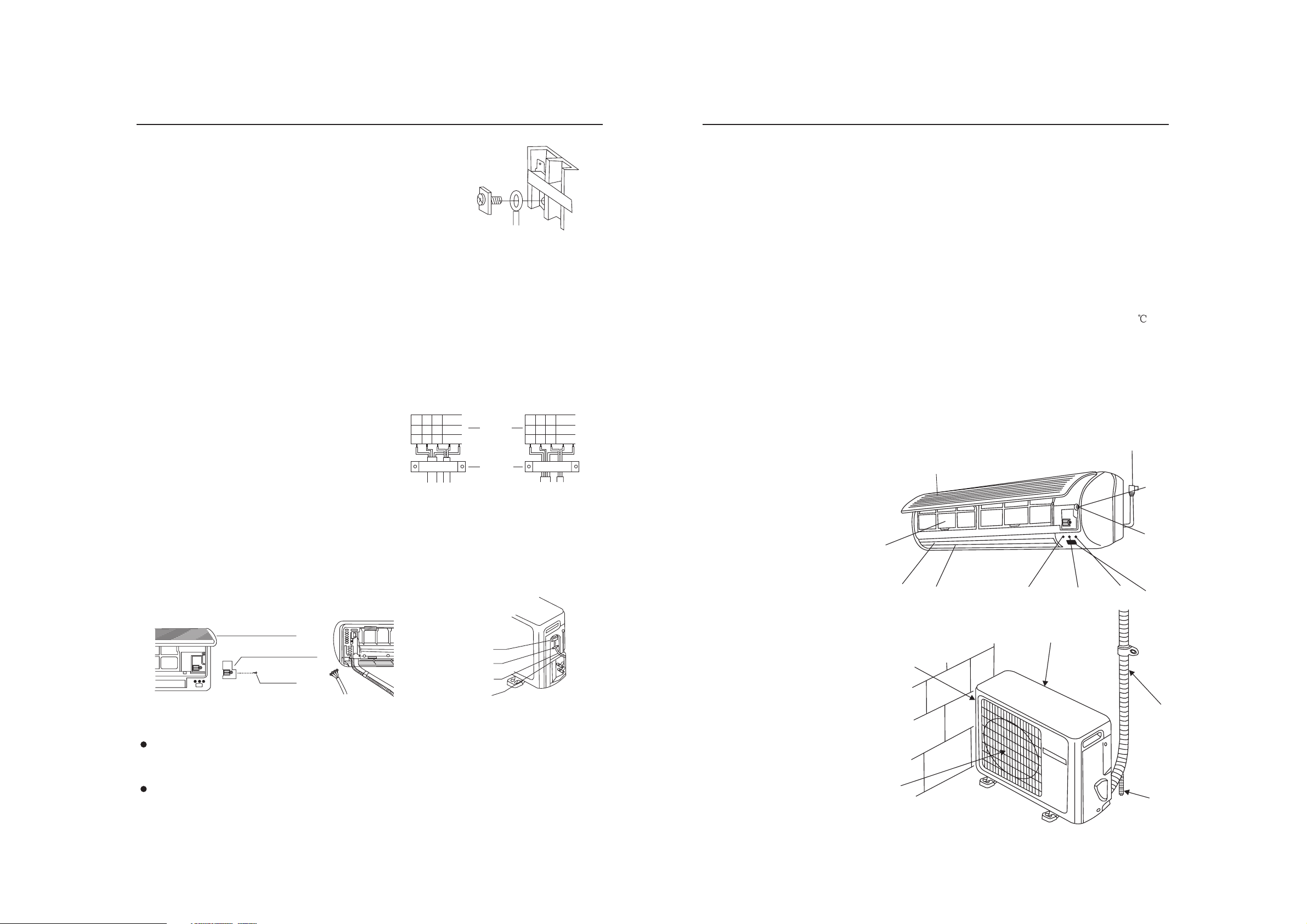
Name of Parts
Wiring for Indoor and Outdoor Units
1. Wiring Method for Ring Terminal
The wiring method is as the drawing below for the ring terminal:
Remove the connection screw and put the screw through the ring on
the connection wire terminal, then connect it to the terminal blocks,
then screw it tightly.
Wiring Method for
2.Wiring Method for Line Terminal
The wiring method is as follows for the non-ring terminal:
Loosen the connection screw and insert the connection wire end into the
terminal block completely, screw it tightly, then slightly pull out the
connection wire to ensure it be clamped tightly.
3. Method for Pressing the Connection Wire
After wiring, the connection wire must be pressed tightly with a wirepressing clip, which should press the outer sleeves of the wire as the
right drawing:
Wiring for Indoor Unit and Outdoor Unit
Lay out the connection wires as the connection drawing (Notes: The two ends of the connection
wires are different, never connect reversely)
1) Open the wire cover, unscrew the pressing clamp(outdoor unit).
2) Connect the connection wires as per the wiring method and the wiring drawing (the wires on
the indoor unit shall be inserted from behind as the attached drawing).
3) Ensure that the terminals are clamped tightly, and press the connection wires(outdoor unit) as
per the pressing method, then install the wire-pressing cover.
Air Inlet Grille
Pressing Cover
Screw
Correct Pressing Wrong Pressing
Terminals
Pressing Clamp
Power Supply Wire
Indoor and Outdoor
Connec ion Wirest
Ring Terminal Block
Terminal
block
Pressing
Clamps
Indoor Unit:
1. Inlet Grill
2. Anion Generator (inside)
3. Air Filter
4. Swing louver
It can be adjusted to upward or downward with the remote controller only (Do not adjust it manually)
5. Power or Healthy Operation Indicator
After the air conditioner is started, this indicator lights up; when the healthy operation is started,this
indicator turns green.
6. Timer Set Indicator
When the air conditioner is at the state of time-set, this indicator lights up.
7. Test
8. Emergency Manual Button
9. Remote Signal Receiving Window
10. Working Method Indicator
11. Power Plug
Manual Button
This button is only used for test refrigerating operation when the room temperature is below 16 , so it
should not be used in normal situation.
When the remote controller is lost or cannot be used, this button can make the air conditioner continue
to operate for the time being.
It receives the remote signal from the remote controller.
When the compressor is working, the indicator lights up .
11
1
Outdoor Unit:
1. Inlet
2. Outlet
Send out hot air when cooling,
and send out cold air when heating .
3. Inlet
4. Connection pipe and electric wiring.
5. Drain Hose
3
2
4
5
6
10
3
1
7
8
9
4
Notes:
When connecting the wires of indoor and outdoor units, check the numbers on the terminals
of the indoor and outdoor units,the same wire shall connect the same number and color
terminal
Wrong connection would damage the air conditioner,s controller,or the unit cannot work.
2
5
Name of Parts
9
Installation
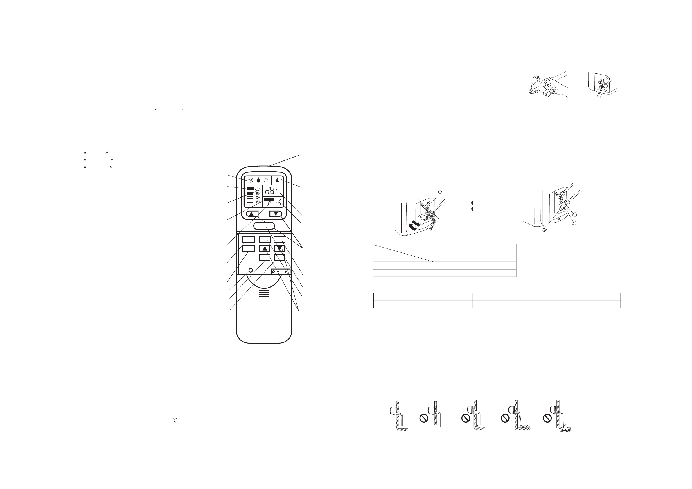
Remote Controller:
Introduction to Display and Function:
1. Mode
Mode selected is displayed
2. Air Volume
Indicating the air speed, when automatic is set, the air speed changes according to the temperature
difference between the indoor temperature and set temperature.
3. Healthy Operation
Indicating healthy operation
4. Timing Mode Display
Indicating time set mode:
Normal for non-time-set;
Timed off for timed turning off;
Timed on for timed turning on;
5. Indicating the Time set
Indicating the time set on and off
6. Mode Selection
Selecting the modes below:
cooling, dehumidifying, and heating
7. Timer
Used to select TIMER ON, TIMER OFF
8. Time Set
1
2
3
4
AUTO
ion
ON OFF
TEMP
ON/OFF
C
H
To set the time on and off
9. Signal Sending Head
To send signal into the signal receiver on the indoor unit
10. Signal Display
It blinks when the signal is being sent
11. Temperature Display
5
6
MODE
TIMER
RESET
POWER
HEALTH
FAN
SWING
To display the temperature set
12. Temperature Set
To set the desired room temperature
13. On/Off Button
7
19
17
To turn on and turn off the air conditioner
14. Air Volume
16
To select the desired air speed
15. Air flow Direction
To adjust the air flow direction
16. Healthy Button
To set the healthy operation
17. Power Button
To set super or soft operation
18. Indication for Power Operation
19. Reset
When the remote controller appears abnormal,
use a sharp pointed item to press this button to
reset the remote controller to normal condition.
Notes: After replacing the batteries in the remote controller, press on/off button, the mode is resumed
as below:
Mode: Refrigerating; Temperature:26
Timer: Normal; Fan Speed: Automatic
4
Piping Connection for Outdoor Unit
Connect the Piping and Inlet and Outlet Liquid Tubes
Gas Drainage Method:
Drain the air in the indoor unit and the pipes as per the drawing:
(1) Remove the valve cap on the two-way valve of the indoor unit with a spanner.
(2) Unscrew by 1/2 cycle the nut on the mouth of the thick pipe connected with the three-way valve
with a spanner.
(3) Unscrew the spool of the two-way valve by 90 with an inner hexagon spanner, and after about 10
o
seconds,close the two-way valve,then air will be drained out from the mouth of the thick pipe. When
the air is drained out, screw tightly the nut on the mouth according to there quired torque.
9
(4) Open the two-way valve and three-way valve with an inner hexagon spanner.
(5) Check the leakage with soap liquid or a leakage checker.
(6) Screw tightly the two valve caps according to the required torque.
10
11
18
Two-way Valve
90
Open
Liquid Side
6.35mm(1/4")
Gas Side
Mouth Nut
Three-way Valve
9.52mm(3/8")
12.7mm(1/2")
Required Torque
12
Torque Tight screw N. M
Specif.
14
Valve Spool
Valve Cap
7-9
20-25
When the connection pipe is more than 5 cm, it shall be filled with refrigerant as per the following
13
15
8
form:
Pipe Length
Refrigerant filled5mnone
7m
32g
10m
80g
15m
160g
Notes: When the pipe is extended, the air in the connection pipe shall be drained out with the
refrigerant(R22) from outside the system, then the excess refrigerant shall be drained out as per the air
drainage method.
Check the Layout of the Drain Pipe and Connection Wires
The drain pipe should be placed underneath, and the connection
wires should be plac upside; and the drain pipe especially the
ed
section inside the machine and indoors must be wound up with
insulating material to preserve heat
The drain pipe shall be sloped and no concave and convex shall
occur along the whole pipe. And the cases as the right drawing
indicates shall not occur.
Prohibited Prohibited Prohibited Prohibited
Correct Up-bent End in the Water Ripple Bad Smell in the Pool
2
 Loading...