

Haier HSU-09RQ03/R2 - annexe 1, HSU-07RE03/R2, HSU-09RE03/R2, HSU-12RE03/R2, HSU-18RE03/R2 Installation Manual
...
No.0010515889
Installation Manual of Room Air Conditioner
Drawing for the installation of indoor and outdoor units
Read this manual before installation
1.Driver
2.Hacksaw
3.Hole core drill
4.Spanner(17,19 and 26mm)
5.Torque wrench(17mm,22mm,26mm)
6.Pipe cutter
7.Flaring tool
8.Knife
9.Nipper 12.Reamer
10.Gas leakage detector or
soap-and-water solution
11.Measuring tape
Explain sufficiently the operating means to the user
according to this manual.
Necessary Tools for Installation
The models adopt HFC free refrigerant R410A
A
B
C
D
E
F
G
Optional parts for piping
Mark
Parts name
Non-adhesive tape
Adhesive tape
Saddle(L.S) with screws
Connecting electric cable
for indoor and outdoor
Drain hose
Heating insulating material
Piping hole cover
No. Accessory parts
Remote controller
R-03 dry battery
Mounting plate
Drain-elbow
1
1
2
3
4
5
6
2
1
4
1
1
Number
of
articles
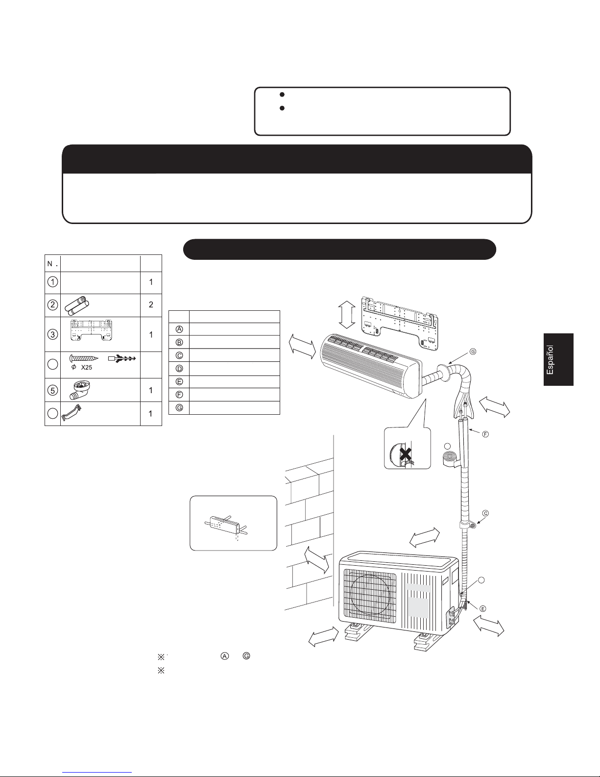
Accessory parts
Pipe supporting plate
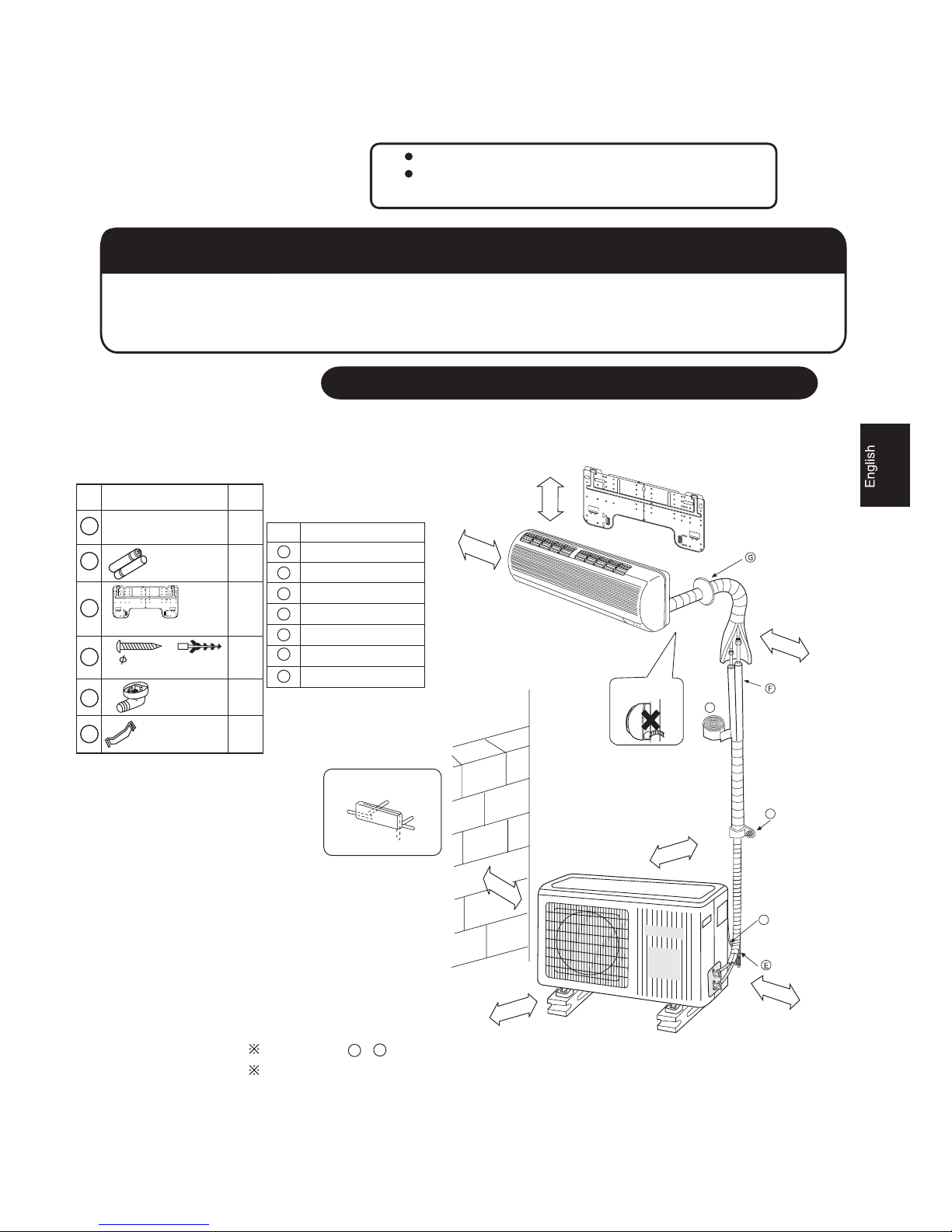
Arrangement of piping directions
Rear left
Rear
right
Left
Below
Right
The marks from to in the figure are the parts numbers.
The distance between the indoor unit and the floor should be
more than 2m.
A
G
Attention must be paid to
the rising up of drain hose
more than 5cm
more than 10cm
more than 10cm
more than 10cm
more than 60cm
more than 15cm
more than 10cm
A
C
D
Screw
Plastic cap
4X25
2
Fixing of outdoor unit
Fix the unit to concrete or block with bolts( 10mm) and nuts firmly and horizontally.
When fitting the unit to wall surface, roof or rooftop, fix a supporter surely with nails
or wires in consideration of earthquake and strong wind.
If vibration may affect the house, fix the unit by attaching a vibration-proof mat.
Indoor Unit
Selection of Installation Place
Outdoor Unit
Place, robust not causing vibration, where the body can be supported
sufficiently.
Place, not affected by heat or steam generated in the vicinity, where
inlet and outlet of the unit are not disturbed.
Place, possible to drain easily, where piping can be connected with the
outdoor unit.
Place, where cold air can be spread in a room entirely.
Place, nearby a power receptacle, with enough space around. (Refer
to drawings).
Place where the distance of more than lm from televisions, radios,
wireless apparatuses and fluorescent lamps can be left.
In the case of fixing the remote controller on a wall, place where the
indoor unit can receive signals when the fluorescent lamps in the room
are lightened.
Place, which is less affected by rain or direct sunlight and is
sufficiently ventilated.
Place, possible to bear the unit, where vibration and noise are
not increased.
Place, where discharged wind and noise do not cause a
nuisance to the neighbors.
Place, where a distance marked is available as illustrated
in the above figure.
Power Source
Before inserting power plug into receptacle, check the voltage without fail. The power source is the same as the corresponding name plate.
Install an exclusive branch circuit of the power.
A receptacle shall be set up in a distance where the power cable can be reached. Do not extend the cable by cutting it.
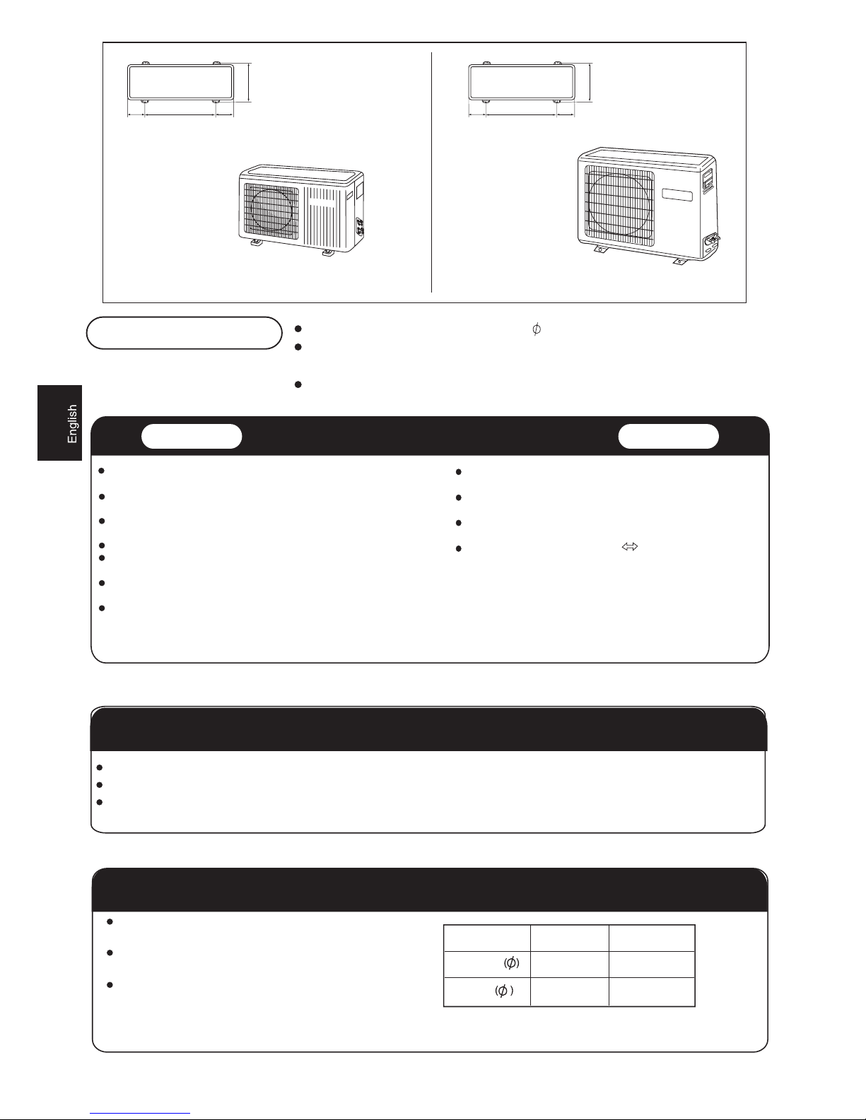
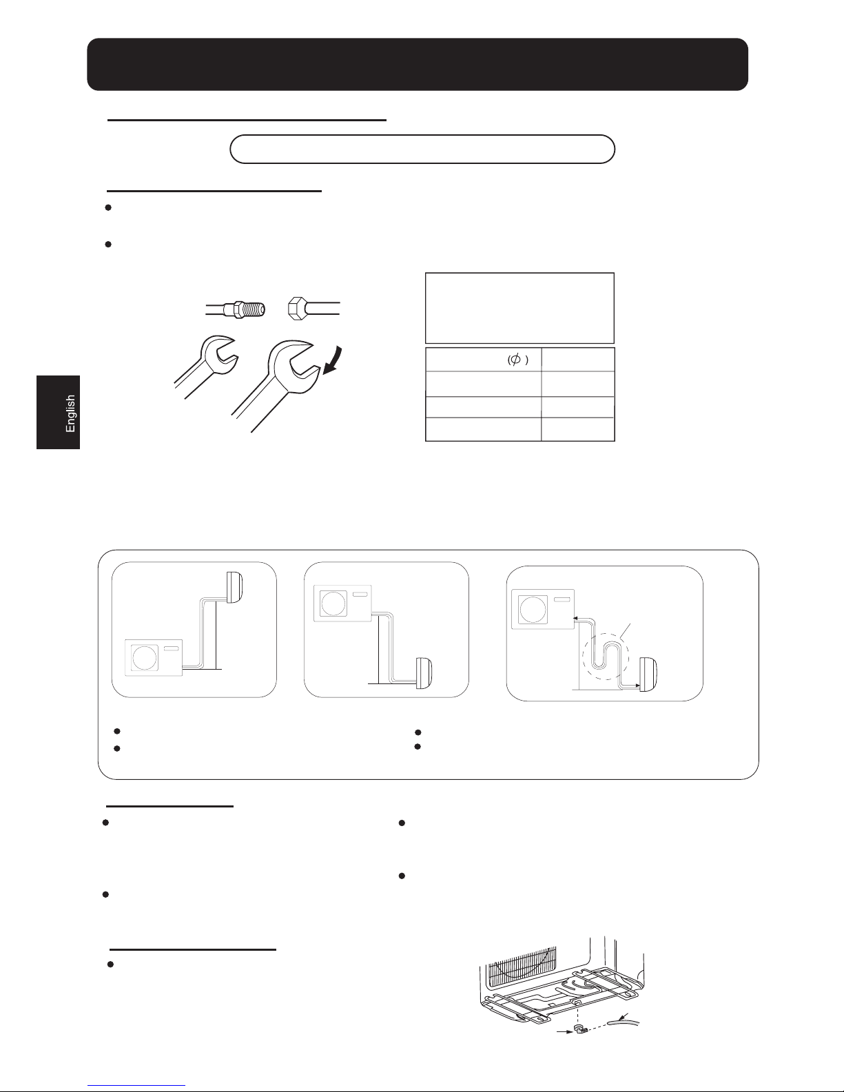
Selection of pipe
To this unit, both liquid and gas pipes shall be insulated
as they become low temperature in operation.
Use optional parts for piping set or pipes covered with
equivalent insulation material.
The thickness of the pipe must be 0.8mm at least.
Liquid pipe
Gas pipe
6.35mm(1/4")
9.52mm(3/8")
6.35mm(1/4")
12.7mm(1/2")
07,09,12 18,22
HSU-07RE03/R2
HSU-09RE03/R2
HSU-12RE03/R2
Floor fixing dimensions
of the outdoor unit
(Unit:mm)
140
415
140
082
Floor fixing dimensions
of the outdoor unit
(Unit:mm)
140
500
140
6
5
2
HSU-18RE03/R2
HSU-22RE03/R2
HSU-09RF03/R2
HSU-12RF03/R2
HSU-09RQ03/R2
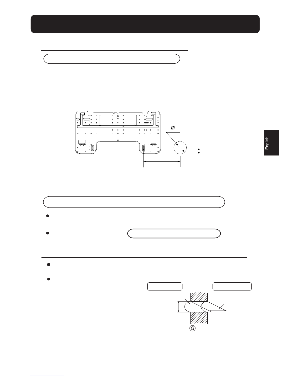
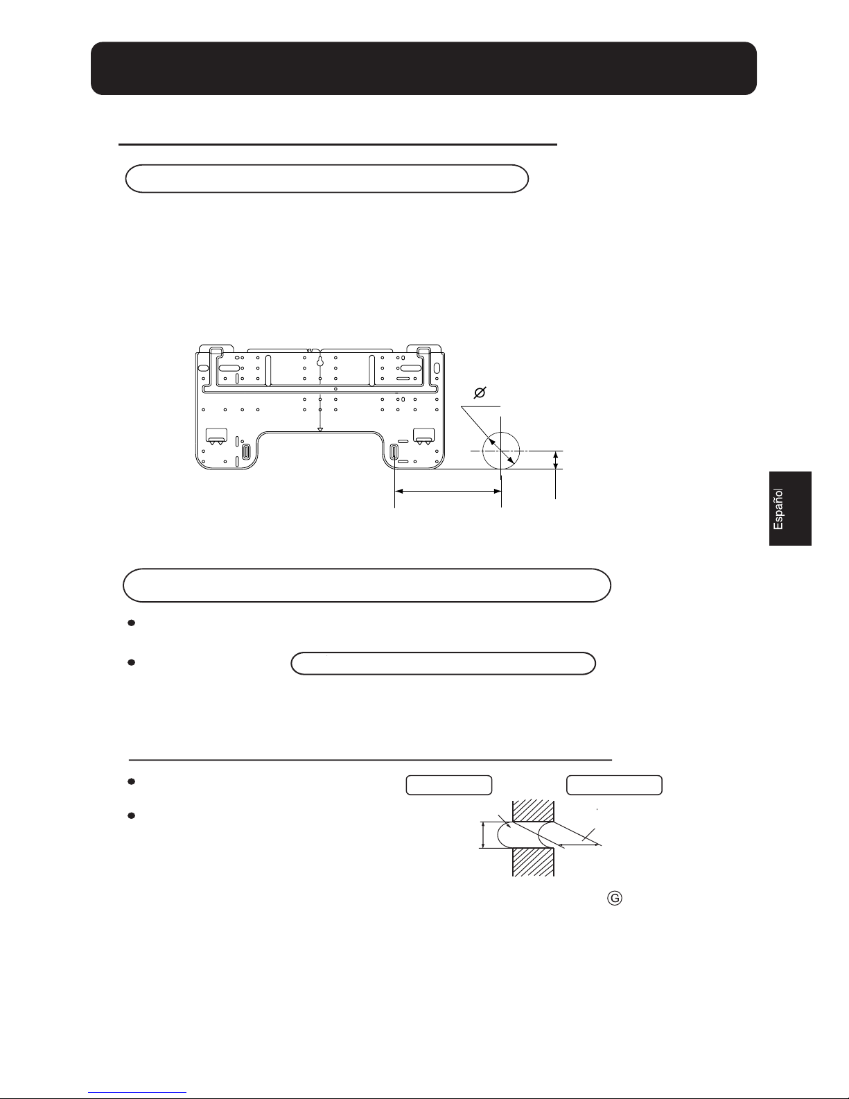
2.Making a Hole on the Wall and Fitting the Piping Hole Cover
When the mounting plate is fixed side bar and lintel
Refer to the previous article, " When the mounting plate is first fixed ", for the
position of wall hole.
Fix to side bar and lintel a mounting bar, Which is separately sold, and then fasten
the plate to the fixed mounting bar.
Make a hole of 60 mm in diameter,
slightly descending to outside the wall.
Install piping hole cover and seal it
off with putty after installation
(Section of wall hole)
Piping hole pipe
Outdoor side
Thickness
of wall
Indoor side
Wall hole
60mm
Indoor unit
1.Fitting of the Mounting Plate and Positioning of the wall Hole
When the mounting plate is first fixed
1.Carry out, based on the neighboring pillars or lintels, a proper leveling for the plate to be
fixed against the wall, then temporarily fasten the plate with one steel nail.
2. Make sure once more the proper level of the plate, by hanging a thread with a weight from
the central top of the plate, then fasten securely the plate with the attachment steel nail.
3. Find the wall hole location A using a measuring tape
3
# PP
$
OO
PP
Indoor unit
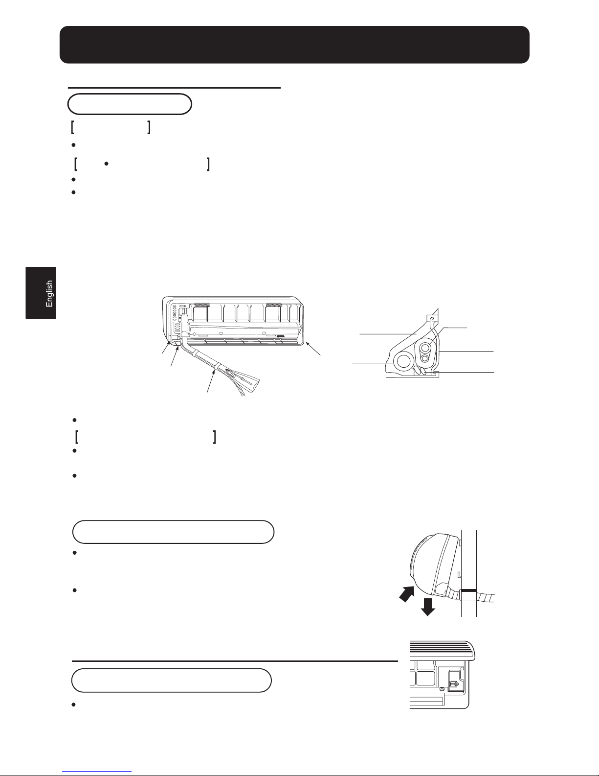
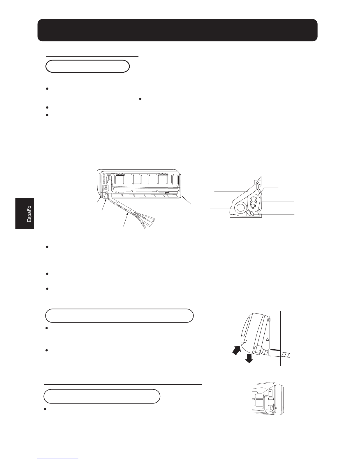
3.Installation of the Indoor Unit
Drawing of pipe
Rear piping
Left Left-rear piping
Draw pipes and the drain hose, then fasten them with the adhesive tape
In case of left side piping, cut away, with a nipper, the lid for left piping.
In case of left-rear piping, bend the pipes according to the piping direction to the mark of hole for left-rear
piping which is marked on heat insulation materials.
1. Insert the drain hose into the dent of heat insulation materials of indoor unit.
2. Insert the indoor/outdoor electric cable from backside of indoor unit, and pull it out on the front side, then
connect them.
3. Coat the flaring seal face with refrigerant oil and connect pipes.
Cover the connection part with heat insulation materials closely, and make sure fixing with adhesive tape
Other direction piping
Indoor/outdoor electric cable and drain hose must be bound with refrigerant piping by protecting tape.
Cut away, with a nipper, the lid for piping according to the piping direction and then bend the pipe according
to the position of wall hole. When bending, be careful not to crash pipes.
Connect beforehand the indoor/outdoor electric cable, and then pull out the connected to the heat insulation
of connecting part specially.
Lid for right piping
Lid for under piping pipe
Lid for left piping
Heat insulation
material
Drain hose
Piping
Indoor/outdoor
electric cable
Fix with adhesive tape
Pipe supporting plate
Fixing the indoor unit body
Hang surely the unit body onto the upper notches of the
mounting plate. Move the body from side to side to verify
its secure fixing.
In order to fix the body onto the mounting plate,hold up
the body aslant from the underside and then put it down
perpendicularly.
4
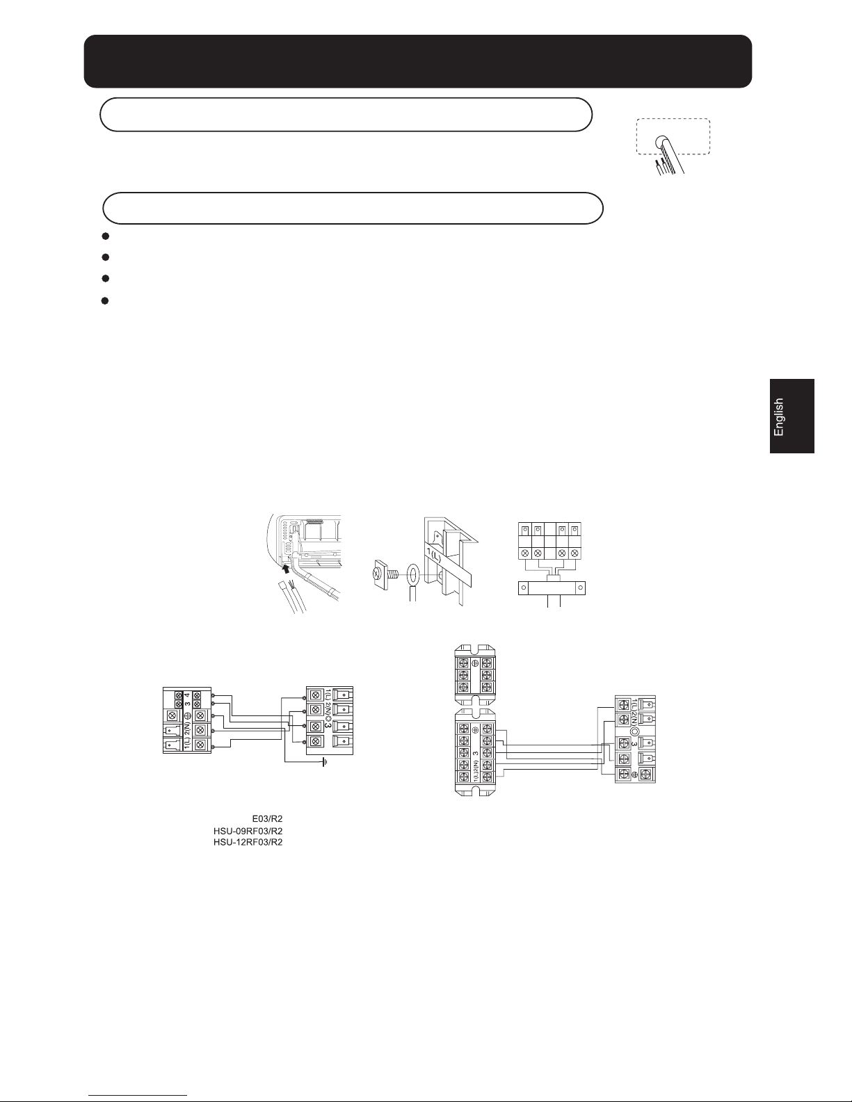
4.Connecting the indoor/outdoor Electric Cable
Removing the wiring cover
Remove terminal cover at right bottom corner of indoor unit, then
take off wiring cover by removing its screws.
Indoor unit
When connecting the cable after installing the indoor unit
1. Insert from outside the room cable into left side of the wall hole, in which
the pipe has already existed.
2. Pull out the cable on the front side, and connect the cable making a loop.
When connecting the cable before installing the indoor unit
Insert the cable from the back side of the unit, then pull it out on the front side.
Loosen the screws and insert the cable ends fully into terminal block, then tighten the screws.
Pull the cable slightly to make sure the cables have been properly inserted and tightened.
After the cable connection, never fail to fasten the connected cable with the wiring cover.
Note: When connecting the cable, confirm the terminal number of indoor and outdoor units carefully. If wiring
is not correct, proper operation can not be carried out and will cause defect.
1. If the supply cord is damaged, it must be replaced by the manufacturer or its service agent or a similar
qualified person. The type of connecting wire is H05RN-F or H07RN-F.
2. If the fuse on PC board is broken please change it with the type of T. 3.15A/250V.
3. The wiring method should be in line with the local wiring standard.
4. After installation, the power plug should be easily reached.
5
HSU-07RE03/R2
HSU-09RE03/R2
HSU-12R
5. A breaker should be incorporated into fixed wiring. The breaker should be all-pole switch and the
distance between its two contacts should be not less than 3mm
Indoor unit
Outdoor unit
4
4
+2x0.75mm
2
LN
G
UL
P
R
E
W
O
P
{
HSU-18RE03/R2
HSU-22RE03/R2
(For:18)
(For:22)
Power cable: *PP
2
Indoor unit
Outdoor unit
4
*5mm
2
Connecting wiring:
Power cable: *5mm
2
Power cable: *5mm
2
*5mm
2
Connecting wiring:
()
HSU-09RQ03/R2
2XWGRRUXQLW
,QVWDOODWLRQRI2XWGRRU8QLW
&RQQHFWLRQRISLSHV
,QVWDOODFFRUGLQJWR
7REHQGDSLSHJLYHWKHURXQGQHVVDVODUJHDVSRVVLEOHQRWWRFUXVKWKHSLSHDQGWKHEHQGLQJUDGLXV
VKRXOGEHWRPPRUORQJHU
&RQQHFWLQJWKHSLSHRIJDVVLGHILUVWPDNHVZRUNLQJHDVLHU
7KHFRQQHFWLRQSLSHLVVSHFLDOL]HGIRU5$
'UDZLQJIRUWKHLQVWDOODWLRQRILQGRRUDQGRXWGRRUXQLWV
+DOIXQLRQ
)ODUHQXW
)RUFHGIDVWHQLQJZLWKRXWFDUHIXO
FHQWHULQJPD\GDPDJHWKH
WKUHDGVDQGFDXVHDOHDNDJHRI
JDV
3LSH'LDPHWHU
)DVWHQLQJWRUTXH
6SDQQHU
7RUTXHZUHQFK
/LTXLGVLGHPP
1P
*DVVLGHPP
*DVVLGHPP
1P
1P
%HFDUHIXOWKDWPDWWHUVVXFKDVZDVWHVRIVDQGVHWFVKDOOQRWHQWHUWKHSLSH
7KHVWDQGDUGSLSHOHQJWKLVP,ILWLVRYHUPWKHIXQFWLRQRIWKHXQLWZLOOEHDIIHFWHG,IWKHSLSHKDV
WREHOHQJWKHQHGWKHUHIULJHUDQWVKRXOGEHFKDUJHGDFFRUGLQJWRJP%XWWKHFKDUJHRIUHIULJHUDQW
PXVWEHFRQGXFWHGE\SURIHVVLRQDODLUFRQGLWLRQHUHQJLQHHU%HIRUHDGGLQJDGGLWLRQDOUHIULJHUDQW
SHUIRUPDLUSXUJLQJIURPWKHUHIULJHUDQWSLSHVDQGLQGRRUXQLWXVLQJDYDFXXPSXPSWKHQFKDUJH
DGGLWLRQDOUHIULJHUDQW
&RQQHFWLRQ
8VHWKHVDPHPHWKRGRQLQGRRUXQLW/RRVHQ
WKHVFUHZVRQWHUPLQDOEORFNDQGLQVHUWWKH
SOXJVIXOO\LQWRWHUPLQDOEORFNWKHQWLJKWHQWKH
VFUHZV
,QVHUWWKHFDEOHDFFRUGLQJWRWHUPLQDOQXPEHU
LQWKHVDPHPDQQHUDVWKHLQGRRUXQLW
,IZLULQJLVQRWFRUUHFWSURSHURSHUDWLRQFDQ
QRWEHFDUULHGRXWDQGFRQWUROOHUPD\EH
GDPDJHG
)L[WKHFDEOHZLWKDFODPS
$WWDFKLQJ'UDLQ(OERZ
,IWKHGUDLQHOERZLVXVHGSOHDVHDWWDFKLWDV
ILJXUH
1RWH2QO\IRUKHDWSXPSXQLW
'UDLQKRVH
'UDLQHOERZ
&$87,21
,QFDVHWKHHOHYDWLRQ$LVPRUHWKDQP
RLOWUDSVKRXGEHLQVWDOOHGHYHU\aP
0D[/HQJWK
%
PD[
P
0D[(OHYDWLRQ
$
PD[
P
,QFDVHWKH
SLSHOHQJWK%LVPRUHWKDQP
WKHUHIULJHUDQWVKRXOGEHFKDUJHGDFFRUGLQJWRJP
,QFDVH$LVPRUHWKDQP
$
%
2XWGRRUXQLW
,QGRRUXQLW
$
%
2XWGRRUXQLW
,QGRRUXQLW
$
%
2XWGRRUXQLW
,QGRRUXQLW
2LOWUDS
Outdoor unit
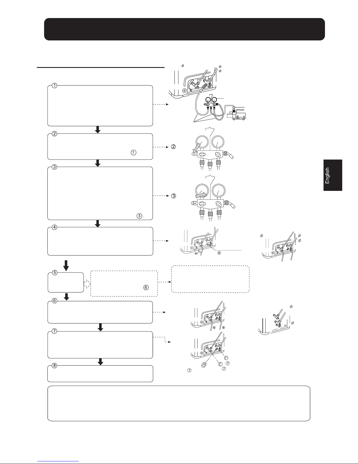
5.Purging Method:To use vacuum pump
Detach the service port's cap of 3-way valve, the
valve rod's cap for 2-way valve and 3-way's, connect
the service port into the projection of charge hose
(low) for gaugemanifold. Then connect the projection
of charge hose (center) for gaugemanifold into
vacuum pump.
Tube(for R410A)
Open the handle at low in gaugemanifold, operate
vacuum pump. If the scale-moves of gause (low)
reach vacuum condition in a moment, check again.
Vacuumize for over 15min. And check the level gauge
which should read -0.1 MPa (-76 cm Hg) at low
pressure side. After the completion of vacuumizing,
close the handle 'Lo' in gaugemanifold and stop the
operation of the vacuum pump.
Check the condition of the scale and hold it for 1-2min.
If the scale-moves back in spite of tightening, make
flaring work again, the return to the beginning of .
Open the valve rod for the 2-way valve to an angle of
anticlockwise 90 degrees.
After 6 seconds, close the 2-way valve and make
the inspection of gas leakage.
No gas leakage?
In case of gas leakage, tighten
parts of pipe connection. If
leakage stops, then proceed
steps.
Detach the charge hose from the service port, open
2-way valve and 3-way. Turn the valve rod anticlockwise
until hitting lightly.
To prevent the gas leakage, turn the service port's
cap, the valve rod's cap for 2-way valve and 3-way's
a little more than the point where the torque increases
suddenly.
After attaching the each caps, check the gas leakage
around the caps.
CAUTION:
1.If the refrigerant of the air conditioner leaks, it is necessary to
discharge all the refrigerant. Vacuumize first, then charge the liquid
refrigerant into air conditioner according to the amount marked on
the name plate.
2.Please do not let other cooling medium, except specified one (R410A),
or air enter into the cooling circulation system. Otherwise, there will be
abnormal high pressure in the system to make it crack and lead to
personal injuries.
If it does not stop gas leakage, discharge
whole refrigerants from the service port.
After flaring work again and vacuumize,
fill up prescribed refrigerant from the gas
cylinder
3-way valve
Gas Side
9.52mm(3/8")
6.35mm(1/4")
2-way valve
3-way valve
Service port cap
Gaugemanifold(for R410A)
Anti countercurrent joint
Vacuum pump(for R410A)
Open
Close
Liquid Side
2-way valve
Valve rod cap
Valve rod cap
2-way valve
9.52mm(3/8")
6.35mm(1/4")
3-way valve
12.7mm(1/2")
Gas Side
Liquid Side
9.52mm(3/8")
Gas Side
6.35mm(1/4")
Liquid Side
2-way valve
3-way valve
2-way valve
3-way valve
3-way valve
2-way valve
Service port
90
o
Open
90ofor 6 sec.
HSU-18RE03/R2
7
HSU-22RE03/R2
12.7mm(1/2")
HSU-07RE03/R2
HSU-09RE03/R2
HSU-12RE03/R2
HSU-09RF03/R2
HSU-12RF03/R2
HSU-09RQ03/R2
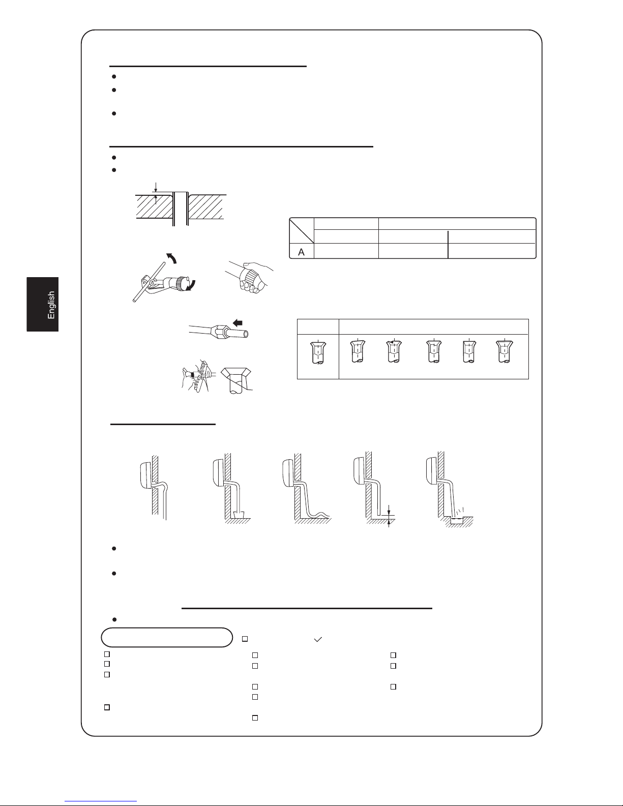
1.Cut pipe
3.Insert the flare nut
4.Flare pipe
It becomes high
midway.
The end is immersed
in water.
It waves. The gap with the ground
is too small
Less than 5cm
There is the bad smell
from a ditch
2.Remove burs
0~0.5mm 1.0~1.5mm 1.5~2.0mm
Flare tool for R410A
Clutch-type
Conventional flare tool
clutch-type(Rigid-type)
Wing-nut type (Imperial-type)
1.Power Source Installation
2.Cutting and Flaring Work of Piping
3.On Drainage
Check for Installation and Test Run
Check Items for Test Run
The power source must be exclusively used for air conditioner. (Over I0A)
In the case of installing an air conditioner in a moist place, please install an
earth leakage breaker.
For installation in other places, use a circuit breaker as far as possible.
Pipe cutting is carried out with a pipe cutter and burs must be removed.
After inserting the flare nut, flaring work is carried out.
Please install the drain hose so as to be downward slope without fail.
Please don't do the drainage as shown below.
Please pour water in the drain pan of the indoor unit, and confirm that drainage is
carried out surely to outdoor.
In case that the attached drain hose is in a room, please apply heat insulation
to it without fail.
Please kindly explain to our customers how to operate through the instruction manual.
Gas leak from pipe connecting?
Heat insulation of pipe connecting?
Are the connecting wirings of
indoor and outdoor firmly inserted
to the terminal block?
Is the connecting wiring of indoor
and outdoor firmly fixed?
Is drainage securely carried out?
Is the earth line securely
connected?
Is the indoor unit securely fixed?
Is power source voltage abided
by the code?
Is there any noise?
Put check mark in boxes
Is the lamp normally lighting?
Are cooling and heating (when
in heat pump) performed normally?
Is the operation of room temperature
regulator normal?
Flare tooling die
Correct
Incorrect
Lean Damage of flare Crack Partial Too outside
A
8
Planos para la Instalación de unidad interior y exterior
4
6
Manual de instalación del Acondicionador de Aire
Lea este manual antes de la instalación
Explicar suficientemente los procesos de
funcionamiento al usuario según este manual
1. Destornillador
2. Sierra
3. Taladro
4. Llave hexagonal (5 mm)
5. Llaves fijas (14,17, 19 y 24 mm)
6. Llaves dinamométricas (17, 22 y 24 mm)
7. Cortador de tubo
8. Herramienta de abocardar
9. Cuchillo
10. Alicates
11. Detector de fugas de gas o
solución de agua jabonosa
12. Cinta de medir
13. Escariador
14. Aceite de refrigeración
Herramientas necesarias para la instalación
Accesorios
Num. de
artículos
Accesorios
Mando a distancia
Pila seca R-03
Placa de montaje
Taco de plástico
Tornillo
Codo de drenaje
Placa soporte de tubería
Piezas opcionales para tubería
Marca
Nomb re del elem ento
Cinta no adhesiva
Cinta adhesiva
Soporte (lado izquierdo) con tornillos
Cable eléctrico de conexión
para interior y exterior
Manguera de drenaje
Material aislante del calor
Tapa de agujero para tubos
Dispo sició n de las t uberías
Izquierda
Trasera izquierda
Trasera derecha
Derecha
Debajo
más de 10 cm
más de 5 cm
más de 10 cm
Debe prestarse atención a que
la manguera de drenaje no
quede elevada
más de 10 cm
más de 10 cm
más de 15 cm
más de 60 cm
Las marcas de " " a " " en la figura son los números de las piezas
La distancia entre la unidad interior y el suelo debe ser superior a 2 m.
Modelos con refrigerante R410A exento de HFC
4
A
D
9

Fijación de la unidad exterior
Fijar la unidad a hormigón o bloquear con pernos (Ø10 mm ) y tuercas firme y
horizontalmente.
Al fijar la unidad a la superficie de la pared, el tejado o la parte superior del tejado,
fijar un soporte de forma segura con clavos o cables para el caso de que se produzca
un terremoto o rachas de viento muy fuertes.
Si las vibraciones pueden afectar a la casa, fijar la unidad colocando una esterilla a
prueba de vibraciones.
Unidad Interior Unidad Exterior
Selección de lugar de la instalación
La zona deberá ser resistente, no provocar vibraciones, y ser suficientemente
robusta para soportar la unidad.
La zona no se verá afectada por el calor ni el vapor generados en las cercanías,
y la entrada y la salida de la unidad no se verán perturbadas.
La zona podrá drenarse con facilidad, y las tuberías puedan podrán conectarse
con la unidad exterior.
La zona será una en la que el aire frío pueda difundirse por toda una sala.
La zona estará cerca de una toma de tensión, con suficiente espacio alrededor.
(Consultar los planos).
La zona será una en la que se podrá mantener una distancia superior a 1 m
de televisores, radios, aparatos inalámbricos y lámparas fluorescentes.
En el caso de fijar el mando a distancia en una pared, la zona será una en la
que la unidad interior podrá recibir señales cuando se enciendan las lámparas
fluorescentes de la sala.
La zona deberá estar lo más resguardada posible de la lluvia, de la
luz solar directa y deberá estar suficientemente ventilada.
La zona podrá soportar la unidad y no aumentará las vibraciones ni
el ruido.
La zona deberá ser una en la que el ruido y el viento emitido no
provoquen perturbaciones a los vecinos.
La zona será una en la que una distancia marcada esté disponible,
tal como se ilustra en la figura anterior.
Alimentación
Antes de introducir el enchufe en la toma, verificar que no hay errores de tensión. La alimentación es la misma que la de la placa de características
correspondiente.
Instalar un circuito de bifurcación exclusivo.
Se situará un receptáculo a una distancia a la que pueda llegar el cable de alimentación. No alargar el cable cortándolo.
Selección del tubo
En esta unidad, tanto las tuberías de gas como las tuberías de líquido estará
aisladas, ya que se producen temperaturas bajas durante el funcionamiento.
Usar piezas opcionales para él conjunto de tuberías o tuberías recubiertas
con material aislante equivalente.
El grosor de la tubería debe ser, como mínimo, de 0,8mm.
Dimensiones de fijación
en el suelo de la unidad
exterior (Unidad: mm)
Tubo líquido
Tubo gas
6.35mm(1/4")
9.52mm(3/8")
6.35mm(1/4")
12.7mm(1/2")
07,09,12 18,22
HSU-07RE03/R2
HSU-09RE03/R2
HSU-12RE03/R2
140
415
140
280
140
500
140
256
HSU-18RE03/R2
HSU-22RE03/R2
Dimensiones de fijación
en el suelo de la unidad
exterior (Unidad: mm)
HSU-09RF03/R2
HSU-12RF03/R2
HSU-09RQ03/R2
1 Montaje de la placa de montaje y situación de orificio en la pared
Cuando se monte la placa de montaje por vez primera
1 Ejecutar, según los pilares o dinteles circundantes, una nivelación adecuada para la placa que se
vaya a montar en la pared; a continuación, ajustar la placa con una punta de acero.
2 Asegurarse que una vez más del nivel adecuado de la placa colgando un hilo con un peso desde
la parte central superior de dicha placa; a continuación asegurar la placa con una punta de acero
de enganche.
3 Encontrar la posición del orificio de la pared A usando cinta de medición.
Cuando se sujeta la placa de montaje a la barra lateral y al dintel
Fijar una barra de montaje, de venta por separado, al dintel y la barra lateral; a continuación
ajustar la placa a la barra de montaje fija.
Consultar el artículo anterior, "Cuando se monte la placa de montaje por vez primera",
para la situación del orificio en la pared.
2 Perforación de la pared y ajuste de la tapa del orificio de la tubería
Hacer un orificio de 60 mm de diámetro,
descendiendo levemente hacia el exterior de la
pared
Instalar la tapa de la perforación de la tubería y
sellarlo con masilla tras su instalación.
Lado interior
Lado exterior
(Sección del orificio de la pared) Tubo
del orificio de la tubería
Orificio de pared
Grosor de pared
60mm
Unidad Interior
11
# PP
$
OO
PP
3 Instalación de la unidad interior
Esquema de la tubería
[Tubería trasera]
Colocar las tuberías y la manguera de desagüe; a continuación sujetarlas con la cinta adhesiva.
[tubería posterior izquierda izquierda ]
En caso de tubería en el lado izquierdo, cortar, con una pinza la tapa para la tubería izquierda.
En el caso de tubería en la parte posterior izquierda, curvar las tuberías de acuerdo con la dirección de la canalización
según la marca de la tubería posterior izquierda del orificio, que está señala en los materiales de aislamiento térmico.
1. Introducir la manguera de desagüe en el dintel de los materiales de aislamiento térmico de la unidad interior.
2. Introducir el cable eléctrico interior/exterior desde la parte trasera de la unidad interior y sacarlo en el lado
delantero; a continuación conectarlos
3. Aplicar la cara de la junta abocardada con aceite refrigerante y conectar las tuberías.
Tapar totalmente la pieza de conexión con materiales de aislamiento térmico y verificar que se utiliza cinta
adhesiva.
El cable eléctrico interior/exterior y la manguera de desagüe deben unirse con la tubería de refrigerante usando la
cinta protectora.
[Otras tuberías de dirección ]
Cortar, con una pinza, la tapa para la tubería de acuerdo con la dirección de la tubería y, a continuación curvar la
tubería según la posición del orificio en la pared. Al curvar, prestar mucha atención para no romper las tuberías.
Conectar de antemano el cable eléctrico interior/exterior y, a continuación, sacar el conectado al aislamiento térmic
de la pieza de conexión.
Ajuste de la carcasa de la unidad interior
Colgar con seguridad la unidad en las muescas de la placa de
montaje. Mover la unidad de lado a lado para verificar si está
firmemente sujeta.
Para fijar la carcasa en la placa de montaje, elevar el aislante de la
carcasa desde la parte inferior y hacerlo descender de forma
perpendicular.
Tapa para tubería derecha
Tapa para tubería bajo canalización
Fijar con cinta adhesiva
Tapa para tubería izquierda
Material aislante de calor
Manguera de
desagüe
Cable eléctrico interior/exterior
Tuberías
Placa apoyatubo
Unidad Interior
12
4 Conexión del cable eléctrico exterior/interior
Retirada de la tapa del cableado
Quitar la tapa de terminales situada en la esquina inferior derecha de la unidad
interior y, a continuación, quitar la tapa del cableado retirando los tornillos
 Loading...