

Haier HSU-07LEK113, HSU-07HEK113, HSU-18HEK113, HSU-09HEK113, HSU-12HEK113 INSTALLATION
...Page 1
Installation Manual of Room Air Conditioner
Read this manual before installation
Explain sufficiently the operating means to the user
according to this manual.
Necessary Tools for Installation
1.Driver
2.Hacksaw
3.Hole core drill
4.Spanner(17,19 and 26mm)
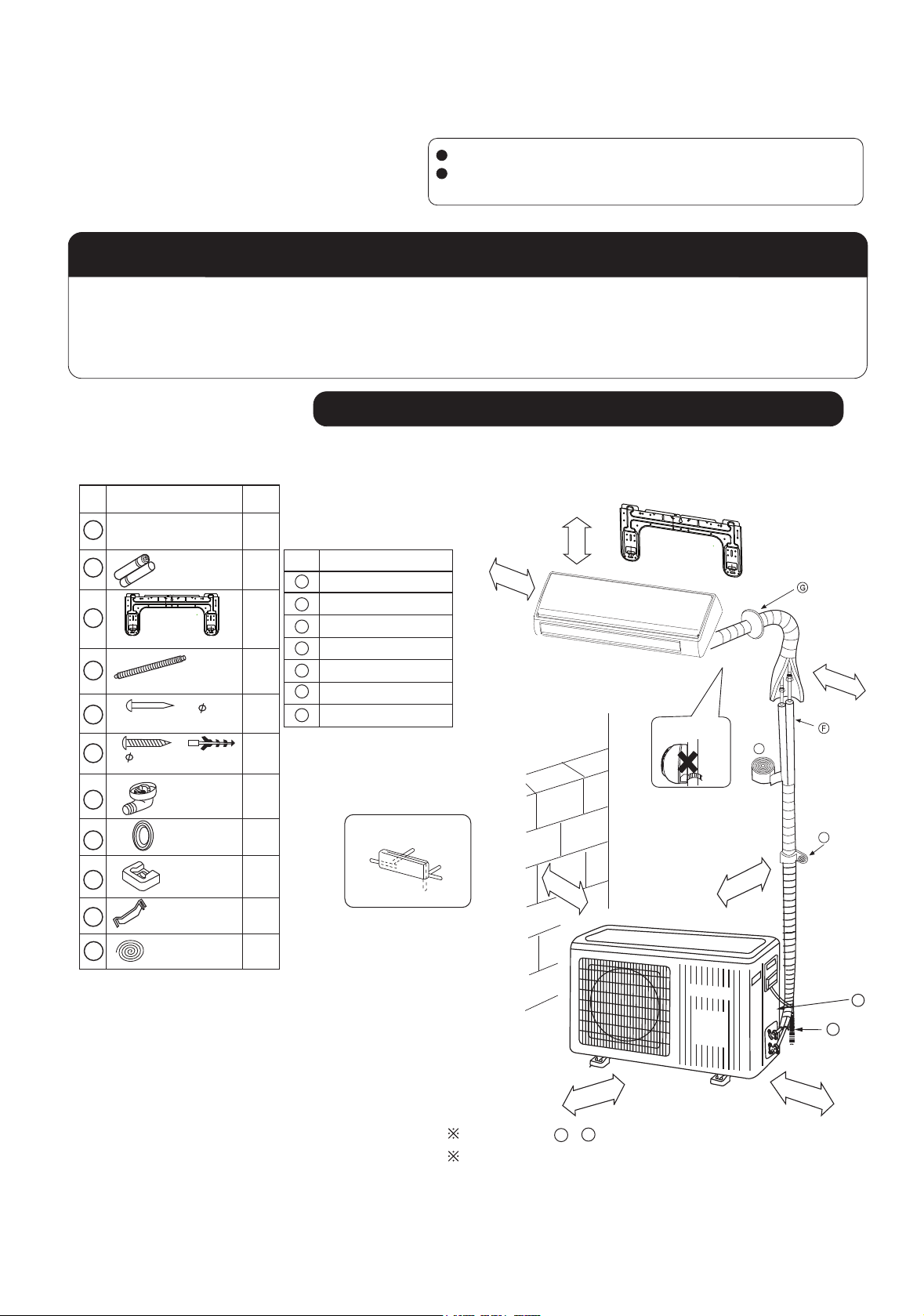
Accessory parts
No. Accessory parts
1
2
3
4
5
6
Remote controller
R-03 dry battery
Mounting plate
Drain hose
Steel nail, cement
4X25
Screw
Plastic cap
4X50
Number
of
articles
1
2
1
1
6
4
5.Torque wrench(17mm,22mm,26mm)
6.Pipe cutter
7.Flaring tool
8.Knife
9.Nipper 12.Reamer
10.Gas leakage detector or
soap-and-
water solution
11.Measuring tape
Drawing for the installation of indoor and outdoor units
mc5nahterom
Optional parts for piping
Mark
A
B
C
D
E
F
G
Parts name
Non-adhesive tape
Adhesive tape
Saddle(L.S) with screws
Connecting electric cable
for indoor and outdoor
Drain hose
Heating insulating material
Piping hole cover
mc01nahterom
Attention must be paid to
the rising up of drain hose
01nahterom
mc
A
1
1
4
1
1
10
11
7
8
9
Drain-elbow
Cover
Cushion
Pipe supporting plate
Connecting cable
Note:Cooling only units don't have Drain-elbow
No.0010535077
Arrangement of piping directions
Rear left
Below
Rear
right
Right
Left
mc
01nah
mc01nahterom
mc
0
6
nahterom
A
The marks from to in the figure are the parts numbers.
G
terom
The distance between the indoor unit and the floor should be
more than 2m.
C
D
E
mc51nahterom
Page 2
140 140415
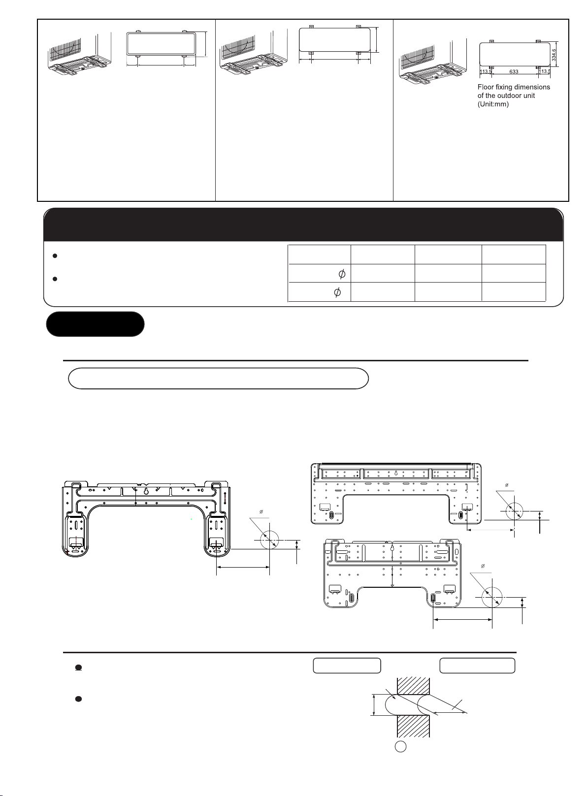
Floor fixing dimensions
of the outdoor unit
(Unit:mm)
HSU-07LEK113
HSU-09LEK113
HSU-12LEK113
HSU-07HEK113
HSU-09HEK113
HSU-12HEK113
280
500
140
Floor fixing dimensions
of the outdoor unit
(Unit:mm)
140
HSU-18LEK113
HSU-18HEK113
Selection of pipe
256
HSU-24LEK113
HSU-24HEK113
To this unit, both liquid and gas pipes shall be insulated
as they become Iow temperature in operation.
Use optional parts for piping set or pipes covered with
equivalent insulation material.
For 07K 09K
Liquid pipe ( )
Gas pipe ( ) 9.52mm(3/8")
6.35mm(1/4")
For 12K 18K
6.35mm(1/4")
12.7mm(1/2")
Indoor unit
1.Fitting of the Mounting Plate and Positioning of the wall Hole
When the mounting plate is first fixed
1.Carry out, based on the neighboring pillars or lintels, a proper leveling for the plate to be
fixed against the wall, then temporarily fasten the plate with one steel nail.
2. Make sure once more the proper level of the plate, by hanging a thread with a weight from
the central top of the plate, then fasten securely the plate with the attachment steel nail.
3. Find the wall hole location A using a measuring tape
B= 60mm
24 K
A=145mm
For 24K
9.52mm(3/8")
15.88mm(5/8")
B= 60mm
30mm
07K , 09 K , 12 K
A=145mm
30mm
18 K
B=
A=145mm
2.Making a Hole on the Wall and Fitting the Piping Hole Cover
Make a hole of 60 mm in diameter,
slightly descending to outside the wall.
Install piping hole cover and seal it
off with putty after installation
Indoor side
Wall hole
60mm
(Section of wall hole)
2
G
Piping hole pipe
Outdoor side
Thickness
of wall
60mm
30mm
Page 3
Indoor unit
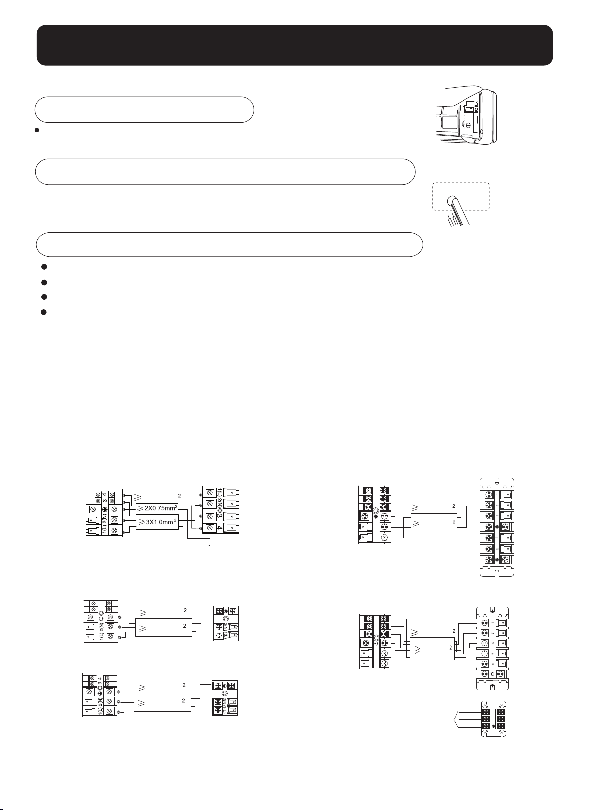
Connecting the indoor/outdoor Electric Cable
Removing the wiring cover
Remove terminal cover at right bottom corner of indoor unit, then
take off wiring cover by removing its screws.
When connecting the cable after installing the indoor unit
1. Insert from outside the room cable into left side of the wall hole, in which
the pipe has already existed.
2. Pull out the cable on the front side, and connect the cable making a loop.
When connecting the cable before installing the indoor unit
Insert the cable from the back side of the unit, then pull it out on the front side.
Loosen the screws and insert the cable ends fully into terminal block, then tighten the screws.
Pull the cable slightly to make sure the cables have been properly inserted and tightened.
After the cable connection, never fail to fasten the connected cable with the wiring cover.
Note: When connecting the cable, confirm the terminal number of indoor and outdoor units carefully. If wi
is not correct, proper operation can not be carried out and will cause defect.
1. If the supply cord is damaged, it must be replaced by the manufacturer or its service agent or a similar
qualified person. The type of connecting wire is H05/07RN-F or 245IEC57(YZW).
2. If the fuse on PC board is broken please change it with the type of T. 3.15A/250V.
If the fuse of outdoor unit on PC board is broken, please change it with the type of T. 25A/250V.
3. The wiring method should be in line with the local wiring standard.
4. After installation, the power plug should be easily reached.
A breaker should be incorporated into fixed wiring. The breaker should be all-pole switch and the
5.
distance between its two contacts should be not less than 3mm.
ring
Indoor unit
43
Indoor unit
Indoor unit
Power cable:
3G1.0mm
HSU-07HEK113
HSU-09HEK113
HSU-12HEK113
HSU-18HEK113
Power cable:
3G1.5mm
3G2.0mm
HSU-18LEK113
Power cable:
3G1.0mm
3G1.0mm
HSU-07LEK113
HSU-09LEK113
HSU-12LEK113
Outdoor unit
Outdoor unit
Outdoor unit
5
4
3
2
1
Indoor unit
5
4
3
2
1
Indoor unit
Power cable:
3G2.5mm
4G0.75mm
HSU-24LEK113
Power cable:
3G2.5mm
6G0.75mm
HSU-24HEK113
POWER
SUPPLY
Outdoor unit
Outdoor unit
BR
BL
Y/G
L
N
3
Page 4
Outdoor unit
Outdoor unit
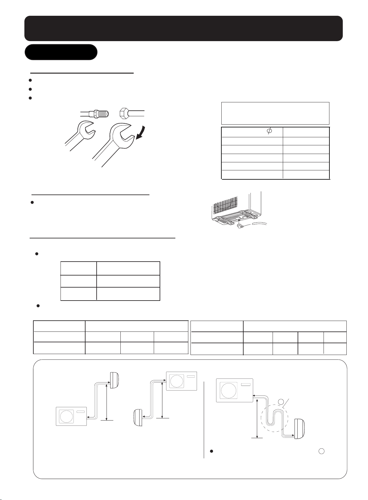
1.Connection of pipes
To bend a pipe, give the roundness as large as possible not to crush the pipe
Connecting the pipe of gas side first makes working easier.
The max vertical distance between the indoor unit and the outdoor unit is 5 m.
Half union
Flare nut
Forced fastening without careful centering
may damage the threads and cause a
leakage of gas.
Pipe Diameter ( )
Spanner
Torque wrench
Be careful that matters, such as wastes of sands, etc.
shall not enter the pipe.
Liquid side 6.35mm(1/4")
Liquid side 9.52mm(3/8")
Gas side 9.52mm(3/8")
Gas side 12.7mm(1/2")
Gas side 15.88mm(5/8")
2.Attaching Drain-Elbow
If the drain-elbow is used, please attach it as
figure. (Note: Only for heat pump unit.)
3.Purging Method:
Push the air out of the indoor unit and piping as followes:
Tighten the caps on the valves with specified torque.
Tighten torque N.m
Valve rod
Valve cap
When connecting pipe exceeds 5 meters, 20g or 60g(only for 24K) refrigerant shall be
added per exceeding meter. Charge according to the following list.
7-9
20-25
Fastening torque
18N.m
40N.m
40N.m
50N.m
60N.m
for 7K 9K 12K 18K
Piping length
Additional amount
Outdoor unit
Max.Elevation:
Max. Length: for 7K 9K : A=7m
for 12K : A=10m
for 18K 24K : A=20m
5m 7m
No need 40g
Indoor unit
A
B
for 7K 9K 12K : B=5m
for 18K 24K : B=10m
Indoor unit
for 24K
10m
100g
A
Outdoor unit
B
4
Piping length
Additional amount
Outdoor unit
CAUTION
In case more than 5 metres,oil trap
should be installed every 5~7m.
5m 7m
No need
A
B
120g
C
10m
300g
Oil trap
Indoor unit
20m
900g
C
 Loading...