

Haier HSM24HEA03/R2, HUM24HA03/R2, HSM24HEK03/R2 User Manual
Installation Manual of Room Air Conditioner
Preparation
Necessary Tools for Installation
Tor que wr ench
Driver●
Nipper●
Hacksaw●Pipecutter●
Hole core drill●Flaringtool●
Spanner(17,19 and 26mm)●Knife●
Gas leakage detector or●
soap-and-water solution
●
(17mm,22mm ,26mm)
Measuring tape●
Reamer●
Power Source
●
Before inserting power plug into receptacle, check the voltage without fail.
The power
Install an exclusive branch circuit of the power.
●
Areceptacleshallbesetupin a distancewherethepowercablecanbe
●
reached.
sourceisthesameasthe
Donotextendthecablebycuttingit.
corresponding name plate.
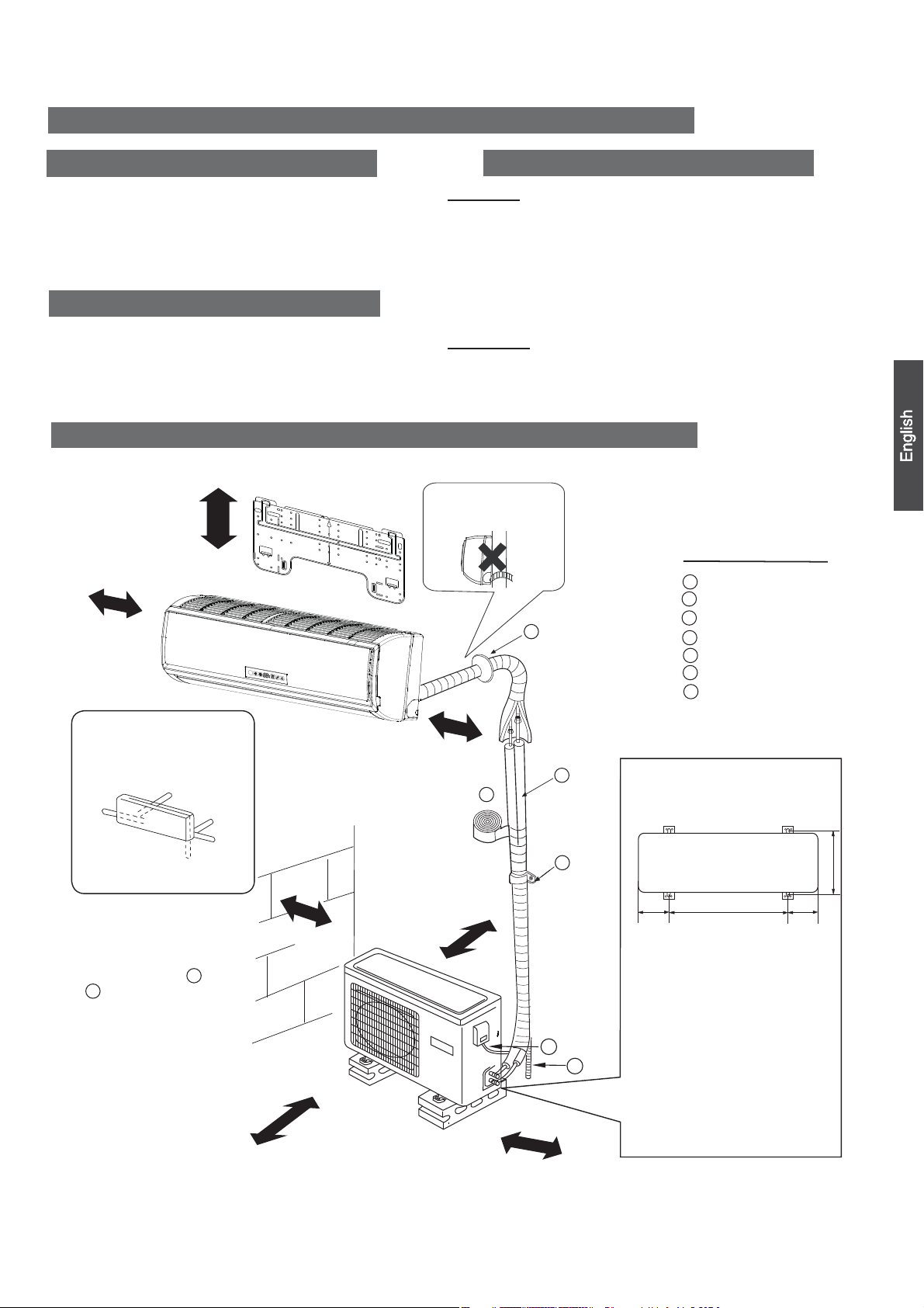
Drawing for the installation of indoor and outdoor units
ThemodelsadoptHFCfreerefrigerantR410A
more than 5cm
more than
10cm
Selection of Installation Place
Indoor Unit
Place,robustnotcausingvibration,wherethebodycanbesupportedsufficiently.●
Place, not affected by heat or steam generated in the vicinity, where inlet and outlet of the
●
unit are not disturbed.
Place, possible to drain easily, where piping can be connected with the outdoor unit.●
Place,wherecoldaircanbespreadin a roomentirely.●
Place, nearby a power receptacle, with enough space around. (Refer to drawings).●
Place where the distance of more than lm from televisions, radios, wireless apparatuses
●
and fluorescent lamps can be left.
In the case of fixing the remote controller on a wall, place where the indoor unit can
●
receive signals when the fluorescent
lampsintheroomarelightened.
Outdoor Unit
Place, which is less affected by rain or direct sunlight and is suf ficiently ventilated.●
Place,possibletobeartheunit,wherevibrationandnoisearenotincreased.●
Place, where discharged wind and noise do not cause a nuisance to the neighbors.●
Place, where a distance marked●
Attention must be paid to
the rising up of drain hose
is available as illustrated in the above figure.
?
Optional parts for piping
Non-adhesive tape
A
Adhesive tape
B
Saddle (L.S) with screws
G
C
Connecting electric cable
D
forindoorandoutdoor
E
Drain hose
F
Heating insulating material
Piping hole cover
G
Arrangement of piping
directions
Left
Rear left
Rear
more than 10cm
F
A
right
Right
Below
The marks from to
●
G
in the figure are the
more than
more than 10cm
A
10cm
C
113.5
parts numbers.
Thedistancebetween
●
the indoor unit and the
floor should be more
than 2m.
D
E
more than
60cm
more than15cm
Please be subject to the actual product purchased , the above picture is just for your reference.
Read this manual before installation
Explain sufficiently the operating means to the user according to this manual.
NO.0010528251
Floor fixing dimensions of the
outdoor unit (Unit:mm)
583
Fixing of outdoor unit
Fix the unit to concrete or block●
with bolts (10mm) and nuts firmly
and horizontally.
●
When fitting the unit to wall
surface, roof or rooftop, fix
a supporter surely with nails
or wires in consideration of
earthquake and strong wind.
●
If vibration may affect the
house, fix the unit by attaching a
vibration-proof mat.
5.91
3
113.5
Remote controller (1)
R-03 dry battery (2)
Mounting plate (1)
Plastic cap (4)
Ø4X25 Screw
NOTE˖The thickness of the pipe must be 0.8mm at least.
(4)
Liquid pipe (Ø) 6.35mm(1/4”)
Gas pipe (Ø)
Indoor unit
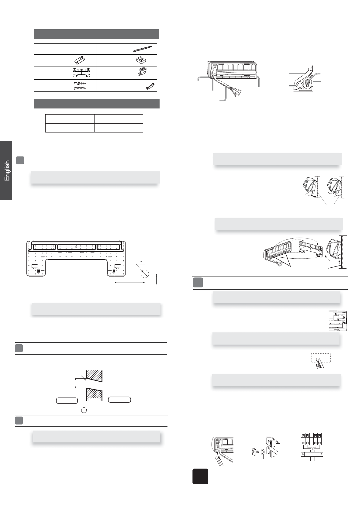
FittingoftheMountingPlateand
Accessory parts
Drain hose (1)
Cushion (4)
Drain-elbow (1)
Pipe supporting plate (1)
Selection of pipe
15.88
PositioningofthewallHole
mm(5/8”)
1. Insert the drain hose into the dent of heat insulation
2. Insert the indoor/outdoor electric cable from backside of
out on the front side, then connect them.
3.Coattheflaringsealfacewithrefrigerantoilandconnect
Cover the connection part with heat insulation materials closely, and make sure
fixing with adhesive tape
Lid for right
piping
Lid for under piping pipe
Fixwithadhesivetape
ƽ
Indoor/outdoor electric cable and drain hose must be bound with refrigerant
piping by protecting tape.
Lid for left piping
materials of indoor unit.
Heat insulation
material
Drain hose
indoor unit, and pull it
pipes.
Indoor/outdoor electric cable
Piping
Pipe supporting
plate
[ Other direction piping ]
ƽ
Cut away, with a nipper, the lid for piping according to the piping direction and
thenbendthepipeaccordingtotheposition of wallhole.Whenbending,be
careful not to crash
ƽ
Connect beforehand the indoor/outdoor electric cable,
connected to the heat insulation of connecting part specially.
pipes.
andthenpulloutthe
Fixing the indoor unit body
When the mounting plate is first fixed
1. Carry out, based on the neighboring pillars or lintels, a
to be fixed against the wall, then
2. Make sure once more the proper level of the plate, by
weight from the central top of the plate, then fasten securely the plate with the
attachment steel nail.
3. Find the wall hole location A using a measuring tape
temporarily fasten the plate with one steel nail.
proper leveling for the plate
hanging a thread with a
B= 70mm
A=150mm
When the mounting plate is fixed side bar and lintel
Fix to side bar and lintel a mounting bar, Which is separately sold, and then
ƽ
fastentheplatetothefixedmountingbar.
Refer to the previous article, “ When the mounting plate is
ƽ
position of wall hole.
Making a Hole on the Wall and Fitting the Piping Hole Cover
Make a hole of 70 mm in diameter, slightly descending to outside the wall.
ƽ
Installpipingholecoverandsealit offwithputty afterinstallation
ƽ
Wall hole
first fixed “, for the
35mm
Hang surely the unit body onto the upper notches of the
ƽ
mountingplate.Movethebodyfromsidetosidetoverifyits
secure fixing.
Inordertofixthebodyontothemountingplate,holdup
ƽ
thebodyaslantfromtheundersideandthenputitdown
perpendicularly.
Unloading of indoor unit body
When you unload the indoor unit,please use
ƽ
your hand to arise the body to leave agraffe,
then lift the bottom of the body outward
slightly and lift the unit aslant until it
leaves the mounting plate.
agraffe
Connecting the indoor/outdoor Electric Cable
Removing the wiring cover
Remove terminal cover at right bottom corner of indoor unit, then takeƽ
off wiring cover by removing its screws.
When connecting the cable after installing the indoor unit
1. Insert from outside the room cable into left side of the wall
hole, in which the pipe has already existed.
2. Pull out the cable on the front side, and connect the cable
making a loop.
mounting plate
mounting plate
Ø70mm
Indoor side
(Section of wall hole)
Installation of the Indoor Unit
Thickness of wall
Piping hole pipe
G
Outdoor side
Drawing of pipe
[ Rear piping ]
Drawpipesandthedrainhose,thenfastenthemwiththeadhesivetape
ƽ
[Left・Left-rear piping ]
ƽ
In case of left side piping, cut away, with a nipper, the lid for left piping.
In case of left-rear piping, bend the pipes according to the piping direction to
ƽ
themark of holeforleft-rearpipingwhichismarkedonheatinsulationmaterials.
2
When connecting the cable before installing the indoor unit
Insertthecablefromthebackƽ
ƽ
Loosen the screws and insert
tighten the screws.
ƽ
Pull the cable slightly to
tightened.
ƽ
After the cable connection,
wiring cover.
When connecting the cable, confirm the terminal number of indoor and
Note
outdoor units carefully. If wiring is not correct, proper operation can not
becarriedoutandwillcausedefect.
side of the unit, then pull it out
thecableendsfullyinto
makesurethecableshave
neverfailtofastentheconnectedcablewiththe
on the front side.
terminal block, then
been properly inserted and
Outdoor unit
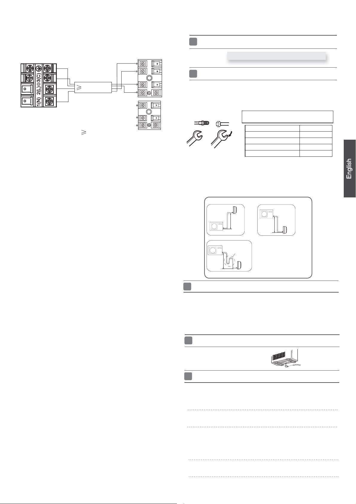
Installation of Outdoor Unit
Indoor unit
4G0.75mm
HSM24HEA03/R2(DB)
HSM24HEK03/R2(DB)
2
POWER
Outdoor unit
{
1
2
3
(C)
1
)
L
(
2
N
)
(
HUM24HA03/R2(DB)
Power cable:
3G2.5mm
1.Ifthesupplycordisdamaged,itmustbereplacedbythemanufacturerorits
service agent or a similar qualified person. The type of connecting wire is
H05RN-F
or H07RN-F.
2.IfthefuseonPCboardisbrokenpleasechangeitwiththe
T. 3.1 5A /2 50V.
3.Thewiringmethodshouldbeinlinewiththelocalwiringstandard.
4. After installation, the power plug should be easily reached.
5. A breakershouldbeincorporatedintofixedwiring.Thebreakershouldbe
all-pole
switchandthedistancebetweenitstwocontactsshouldbenotless
than 3mm.
2
type of
Install according to Drawing for the installation of indoor and
Connection of pipes
ƽ
To bend a pipe, give the roundness as large as possible not to crush the pipe ,
andthebendingradiusshouldbe30to40
ƽ
Connecting the pipe of gas side first makes working easier.
TheconnectionpipeisspecializedforR410A.ƽ
Half union
Spanner
Becarefulthatmatters,suchaswastesofsands,etc.shallnotenterthepipe.
Thestandardpipelengthis5m.Ifitisover7m,thefunctionoftheunitwillbe
affected. If the pipe has to be lengthened, the refrigerant should be charged,
according to 20 g/m. But the charge of refrigerant must
sional air conditioner engineer. Before adding additional refrigerant, perform air
purging from the refrigerant
charge additional refrigerant.
Flare nut
Tor que wr enc h
CAUTION
B
Outdoor unit
Outdoor unit
A
Forced fastening without careful centering may
damage the threads and cause a leakage of gas.
Liquid side6.35mm(1/4") 18N.m
Liquid/Gas side9.52mm(3/8") 42 N.m
Gas side 12.7mm(1/2") 55N.m
Gas side 15.88mm(5/8") 60 N.m
pipes and indoor unit using a vacuum pump,then
Indoor unit
A
Oil trap
B
Indoor unit
mm or longer.
Pipe Diameter(ǿ) Fastening torque
Outdoor unit
B
Indoor unit
A
Max.Elevation:
●
In case the elevation A is more●
than 5m, oil trap shoud be
installed every 5~7m
●
Max. Length:
In case the pipe length B is●
more than 7m, the refrigerant
should be charged, according
to 20g/m.
Amax=15m
Bmax=25m
outdoor units
be conducted by profes-
Connection
Use the same method on indoor unit. Loosen the screws onƽ
insert the plugs fully into terminal block, then tighten the screws.
ƽ
Insert the cable according to terminal number in the same manner as the indoor
unit.
Ifwiringisnotcorrect,properoperationcannotbecarriedoutandcontroller
ƽ
may be damaged.
Fix the cable with a clamp.ƽ
Attaching Drain-Elbow
If the drain-elbow is used,ƽ
please attach it as figure. (Note:
Only for heat pump unit.)
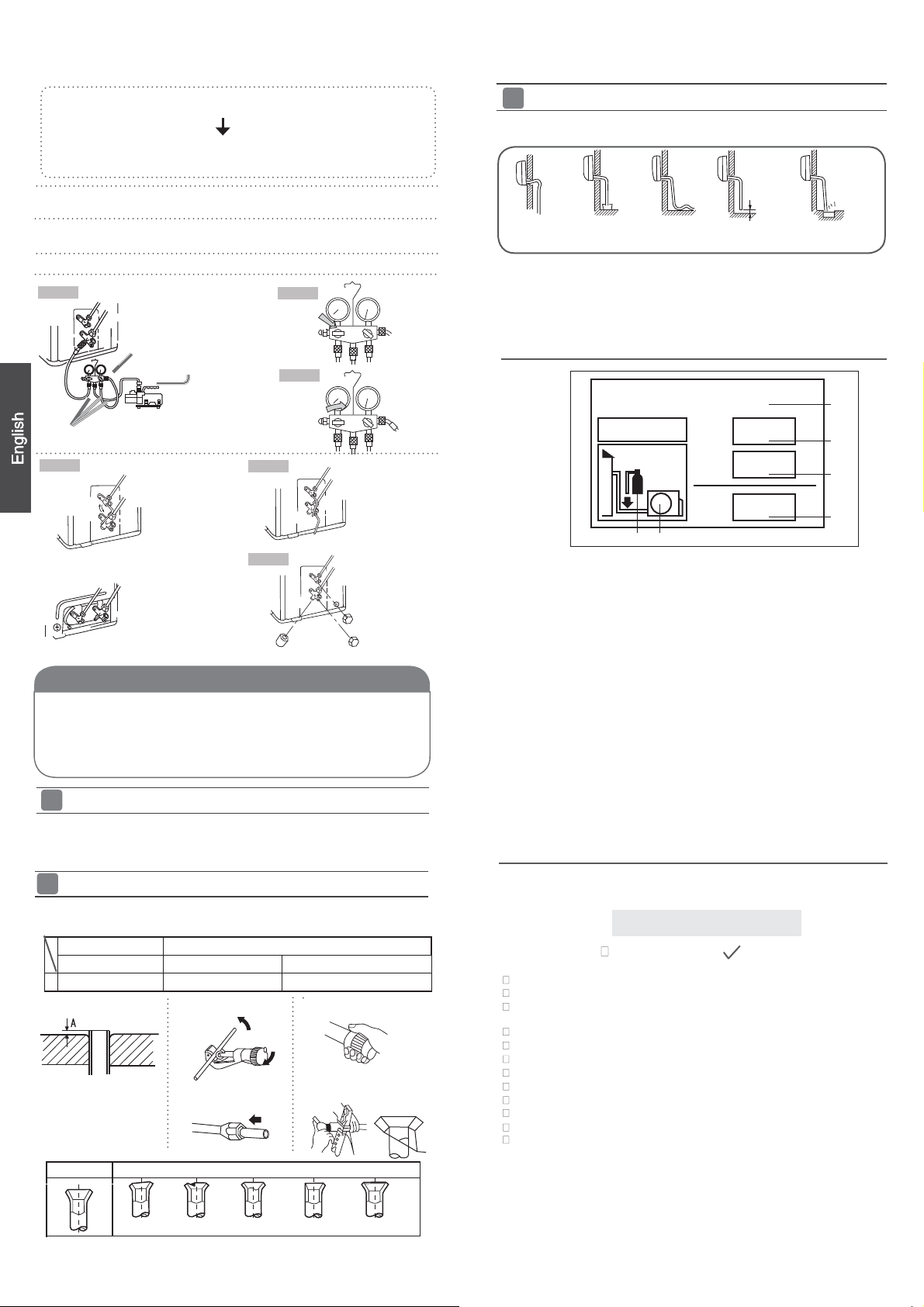
PurgingMethod:Tousevacuumpump
Detach the service port’s cap of
1.
and3-way’s,connecttheserviceportintothe
for gaugemanifold.
gemanifold
Open the handle at Iow in
2.
moves of gause (Iow) reach vacuum condition in a moment, check 1. again.
Vacuumizeforover15min.Andcheckthelevelgaugewhichshouldread-0.1MPa
3.
(76 cm Hg) at Iow
handle ‘Lo’ in gaugemanifold and stop the operation of the vacuum pump. Check
condition of the scale and hold it for 1-2min. If the scale-moves back in spite of
tightening, make flaring work again, the return to the beginning of 3 .
Then connect
into vacuum pump.
pressure side. After the
3-wayvalve,thevalverod’scapfor2-wayvalve
the projection of charge hose (center) for gau-
gaugemanifold, operate
projection of charge hose (Iow)
vacuum pump. If the scale-
completion of vacuumizing, close the
terminal block and
Open the valve rod for the 2-way valve to an angle of4.
After 6 seconds, close the
2-way valve and make the
anticlockwise 90 degrees.
inspection of gas leakage.
3
No gas leakage?5.
In case of gas leakage, tighten parts of pipe connection. If
leakagestops,thenproceed6.steps
If it does not stop gas leakage, discharge whole refrigerants
port. After flaring work again and vacuumize, fill up prescribed
Detach the charge hose6.
the valve rod anticlockwise until hitting lightly.
To prevent the gas
7.
valve and 3-way’s a little more
After attaching the each
8.
Step 1.
2-way valve Liquid Side
3-way valve Gas Side
refrigerantfromthegascylinder.
from the service port,
leakage, turn the service
than the point where the torque increases suddenly.
caps, check the gas
port’s cap, the valve
open2-wayvalveand3-way.Turn
leakage around the caps.
Step 2.
Open
from the service
rod’scapfor2-way
On Drainage
Pleaseinstallthedrainhosesoastobedownwardslopewithoutfail.
ƽ
Pleasedon’tdothedrainageasshownbelow.
ƽ
Less than
5cm
It becomes
high midway.
Please pour water in the drain pan of the indoor unit, and
ƽ
is carried out surely to outdoor.
In case that the attached drain hose is in a room, please
ƽ
to it without fail.
The end is immersed in water.
It waves.
The gap with the
ground is too small
confirm that drainage
apply heat insulation
There is the bad
smell from a ditch
Tube(for R410A)
Step 4.
O
Open 90
2-way valve
Gaugemanifold(for
Anti countercurrent joint
Vacuum pump(for R410A)
2-way valve
3-way valve
3-way valve
R410A)
Step 6.
Step 7.
Service port cap
Step 3.
Close
2-way valve
3-way valve
2-way valve
3-way valve
Valve rod cap
Valve rod cap
CAUTION
ƽ
If the refrigerant of the air conditioner leaks, it is necessary to discharge all the
refrigerant. Vacuumize first, then
neraccordingtotheamountmarkedonthenameplate.
ƽ
Please do not let other cooling medium, except specified one (R410A), or air
enter into the cooling circulation system. Otherwise, there will be abnormal
highpressureinthesystemtomakeitcrackandleadtopersonalinjuries.
Power Source Installation
ƽ
The power source must be exclusively used for air
ƽ
In the case of installing an air conditioner in a moist place,
rth leakage breaker.
ƽ
For installation in other places, use a circuit breaker as far
Cutting and Flaring Work of Piping
Pipe cutting is carried out with a pipe cutter and burs mustƽ
Afterinsertingtheflarenut,flaring workiscarriedout.
ƽ
FlaretoolforR410A Conventionalflaretool
Clutch-type clutch-type(Rigid-type) Wing-nut type (Imperial-type)
A 0~ 0.5mm 1.0~1.5mm 1.5 ~2.0mm
Flare tooling die
chargetheliquidrefrigerantintoairconditio-
conditioner.
please install an ea-
as possible.
be removed.
1.Cut pipe
3.Inserttheflarenut
2.Remove burs
4.Flare pipe
(Over I0A)
Refrigerant charge labelƵ
Contains fluorinated greenhouse gases
covered by the Kyoto Protocol
R410A
2
1=
2=
1
1+2=
FE
kg
kg
kg
A
B
C
D
This product contains fluorinated greenhouse gases covered by
the Kyoto Protocol. Do not vent into the atmosphere.
Refrigerant type:R410A
GWP* value:1975
GWP=global warming potential
Please fill in with indelible ink,
• 1 the factory refrigerant charge of the product
• 2 the additional refrigerant amount charged in the field and
• 1+2 the total refrigerant charge
on the refrigerant charge label supplied with the product.
The filled out label must be adhered in the proximity of the product
charging port (e.g. onto the inside of the stop value cover).
A contains fluorinated greenhouse gases covered by the Kyoto
Protocol
B factory refrigerant charge of the product: see unit name plate
C additional refrigerant amount charged in the field
D total refrigerant charge
E outdoor unit
F refrigerant cylinder and manifold for charging
Ƶ
Check for Installation and Test Run
Please kindly explain to our customers how to operate
Ƶ
through the instruction manual.
CheckItemsforTestRun
Put check mark
Gasleakfrompipeconnecting?
Heat insulation of pipe connecting?
Are the connecting wirings of indoor and outdoor firmly
inserted to the terminal block?
Istheconnectingwiring of indoorandoutdoorfirmlyfixed?
Is drainage securely carried out?
Is the earth line securely connected?
Istheindoorunitsecurelyfixed?
Is power source voltage abided by the code?
Is there any noise?
Is the lamp normally lighting?
Arecoolingandheating(wheninheatpump)performednormally?
Is the operation of room temperature regulator normal?
in boxes
Correct Incorrect
Lean
Damage of flare Crack Partial Too outside
4
Manual de instalación de aparato de aire acondicionado
nóicaraperP
Herramientas necesarias para realizar la instalación
Destornillador Llave dinamométrica (17 mm, 22 mm,
Alicate Sierra de tubos
Sierra para metales Herramienta de conicidad
Broca de tubo Cuchilla
Llave (17, 19 y 26 mm) Metro
Detector de fugas de gas o agua
jabonosa
Fuente de alimentación
Antes de insertar el enchufe de alimentación en la toma, compruebe que el voltaje
no falla. La fuente de alimentación es la que figura en la placa de datos nominales.
Instale el aparato en un circuito dedicado de alimentación.
Debe existir una toma al alcance del cable de alimentación. No prolongue el cable
cortándolo.
Los modelos cumplen la norma R410A sobre refrigerantes libres de HFC
más de 5cm
26 mm)
Avellanador
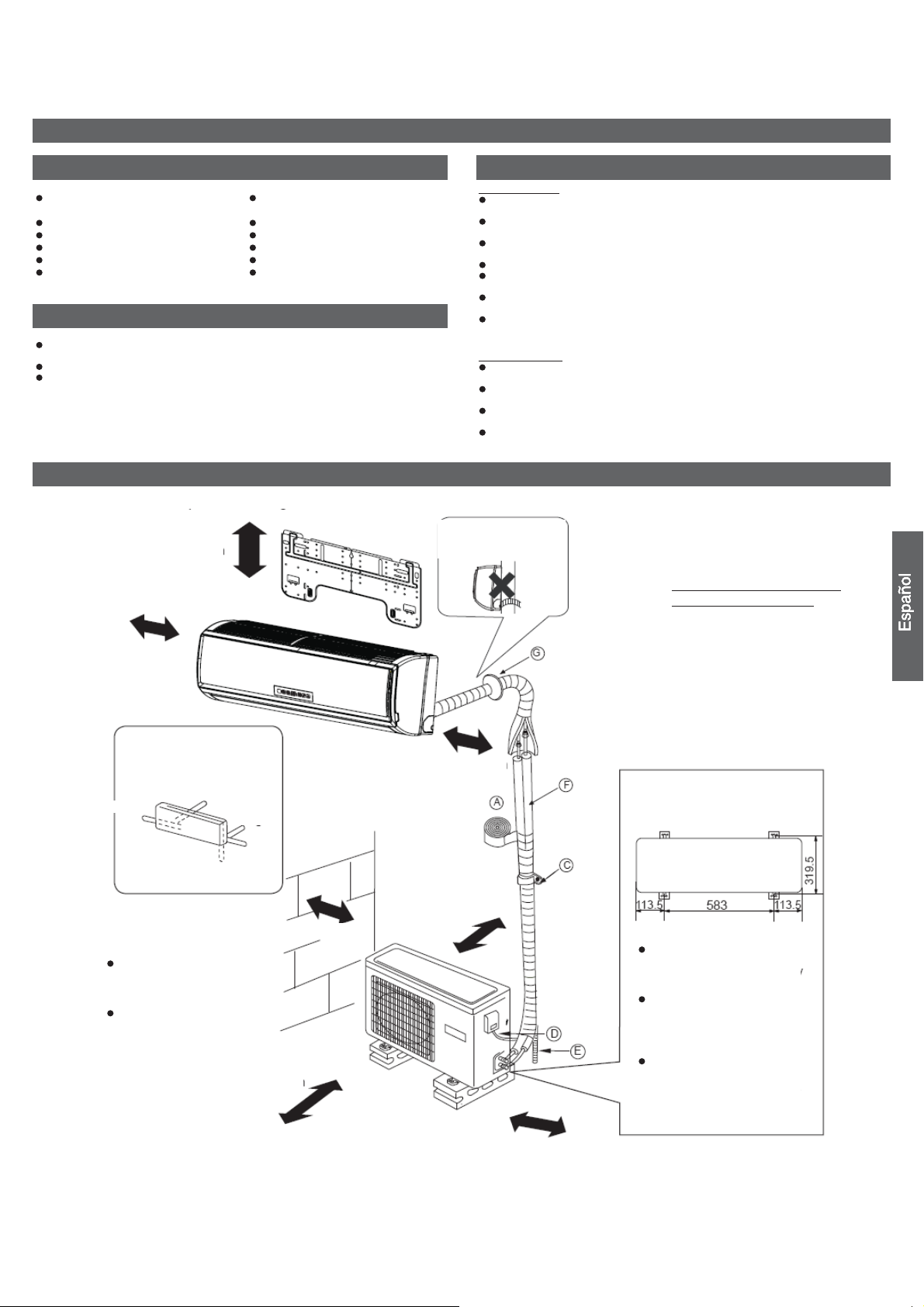
Diagrama para la instalación de aparatos interiores y exteriores
Unidad interior
Coloque la unidad sobre una superficie que pueda soportarla correctamente y no
provoque vibraciones.`
Asegúrese de que el lugar no se ve afectado por calor o vapor generado en las
cercanías y donde la unidad pueda funcionar sin perturbaciones.
Asegúrese de que el lugar permita un drenaje sencillo y en el que puedan
conectarse los tubos a la unidad exterior.
Asegúrese de que el aire frío pueda distribuirse uniformemente por la sala.
Coloque la unidad interior cerca de una toma de suministro eléctrico con espacio
suficiente alrededor. (Consulte los diagramas).
Coloque la unidad interior de modo que se encuentre a más de 1m de televisiones,
radios, aparatos inalámbricos y lámparas fluorescentes.
En el caso de fijar el control remoto a una pared, colóquelo donde la unidad interior
pueda recibir su señal mientras estén encendidas las lámparas fluorescentes de la
sala.
Unidad exterior
Seleccione el lugar menos afectado por la lluvia o la luz solar directa y
suficientemente ventilado.
Elija un lugar que permita soportar el peso de la unidad y que no amplifique el ruido
y las vibraciones.
Seleccione un lugar en el que los residuos y el viento generado por la unidad no
cause una molestia a los vecinos.
Coloque la unidad en un lugar en el que pueda disponerse de la distancia de
separación marcada X en la figura anterior.
Debe prestarse atención a
la pendiente de la
manguera de drenaje
Selección del lugar de instalación
más de 10cm
Organización de la dirección
de los tubos
Izquierda trasera
Izquierda
Inferior
Las marcas comprendidas
entre
A y G en la
ilustración corresponden a
los números de las piezas.
La distancia entre la unidad
interior y el suelo debe ser
superior a 2m.
Derecha
trasera
Derecha
más de 10cm
más de 60cm
más de 10cm
más de 10cm
Componentes opcionales para
la instalación de los tubos
A Cinta no adhesiva
○
B Cinta adhesiva
○
C Soporte (L.S) con tornillos
○
D Conexión de cable eléctrico
○
para interior y exterior
E Manguera de drenaje
○
F Material aislante de calor
○
G Cubierta de orificio de
○
entubación
Dimensiones de fijación al suelo
de la unidad exterior (Unidad:mm)
Fijación de la unidad exterior
Fije la unidad a un bloque de
cemento con pernos (10mm) y
tuercas firme y
horizontalmente.
Si instala la unidad sobre una
pared, techo o tejado, instale
un soporte con clavos o cables
considerando la posibilidad de
terremotos o viento fuerte.
Si la vibración afectase a la
casa, fije la unidad instalando
una alfombra de absorción de
vibraciones.
más de 15cm
Recuerde que la ilustración anterior podría no reflejar fielmente el producto adquirido y debe utilizarse únicamente como referencia.
Lea este manual antes de la instalación
Explique el uso del aparato al usuario siguiendo las instrucciones de este manual.
5
 Loading...