

Haier HL32R-B Service Manual

1
HL32R-B
(MTK5380-AU)

2
WARNING
This service information is designed for experienced repair technicians only and is not designed for use
by the general public. It does not contain warnings or cautions to advise non-technical individuals of
potential dangers in attempting to service a product. Products powered b electricity should be serviced
or repaired only by experienced professional technicians. Any attempt to service or repair the product
deal with in this service information by anyone else could result in serious injury or death.

3
CONTENT
1 .Warning........................................................................................................................................................4
2. Specification.................................................................................................................................................6
3. LOCATION OF CONTROLS AND COMPONENTS ................................................................................7
3.1.Board Location...................................................................................................................................7
3.2. Main Board.....................................................................................................................................7
3.2.1 Function Description...............................................................................................................7
3.2.2 Connector definition................................................................................................................8
3.3 Power Board..................................................................................................................................10
3.3.1 Function Description..........................................................................................................10
3.3.2 Connector definition.............................................................................................................. 11
3.4 LCD PANEL. ................................................................................................................................12
3.4.1 Function Description:............................................................................................................12
3.4.2 Connector definition..............................................................................................................12
4. INSTALLATION INSTRUCTIONS................................................................................................... .......13
4.1 External Equipment Connections.....................................................................................................13
4.2 HDMI CINNECTIONS....................................................................................................................19
5. OPERATION INSTRUCTIONS................................................................................................................22
5.1 Front panel controls..........................................................................................................................22
5.2 Back panel controls..........................................................................................................................23
5.3 Setting Up Your Remote Control...................................................................................................24
6. DISASSEMBLY INSTRUCTIONS...........................................................................................................25
6.1 whole machine..................................................................................................................................26
6.2 Base subassembly.............................................................................................................................27
6.3 Back cover subassembly ...............................................................................................................28
6.4 Screen bracket subassembly..........................................................................................................28
6.5 Front-frame subassembly..............................................................................................................29
6.6 Wire subassembly---- Connection Sketch Interpretat....................................................................30
6.6.1. Wire Photo............................................................................................................................30
6.6.2 Components List....................................................................................................................30
7. MEASUREMENTS AND ADJUSTMENTS.............................................................................................31
8. BLOCK DIAGRAM AND CIRCUIT DIAGRAM....................................................................................34
8.1 BLOCK DIAGRAM ........................................................................................................................34
8.2 CIRCUIT DIAGRAM......................................................................................................................34
9. WIRING CONNECTION DIAGRAM ......................................................................................................50
10. TROUBLE SHOOTING GUIDE.............................................................................................................51
10.1. Simple check.................................................................................................................................51
10.1.1 LCD is not bright.................................................................................................................51
10.1.2 No picture............................................................................................................................51
10.1.3 No sound..............................................................................................................................52
10.2 PSU failure check........................................................................................................................52
10.3 Panel failure.................................................................................................................................53

4
1 .Warning
CAUTION: These servicing instructions are for use by qualified service personn el only. To reduce the
risk of electric shock, do not perform any servicing other than that contained in the operating instructions
unless you are qualified to do so.
IMPORTANT SAFETY INSTRUCTIONS
Read all of the instructions before using this appliance. When using this appliance, always
exercise basic safety precautions, including the following:
Read instructions
Read all of the safety and operating instructions before you use your TV.
Retain instructions
Retain safety and operating instructions for future reference.
Follow warnings and instructions
Follow all warnings on your TV and in the operating instructions. Follow all operating and use instructions.
Water and moisture
Do not use your TV near water. For example, do not use it near a bath tub, wash bowl, kitchen sink, laundry
tub, in a wet basement, or near a swimming pool.
Cleaning
Unplug your TV before cleaning. Do not use liquid or aerosol cleaners. Use only a damp cloth to clean the
exterior of your TV.
Ventilation
Slots and openings in the cabinet and the back or bottom are provided for ventilation, reliable operation, and
protection from overheating.These openings must not be blocked or covered.Do not block the openings by
placing your TV on a bed, sofa, rug, or other similar surface. Do not place your TV near or over a radiator or
heat register. Do not place your TV in a built-in installation, such as a bookcase or rack, unless you provide
correct ventilation or follow the manufacturer’s instruct ions.
Heat
Make sure that your TV is located away from heat sources such as radiators, heat registers,stoves, or other
products (including amplifiers) that produce heat.
Grounding or polarization

5
Do not defeat the safety purpose of the polarized or grounding-type plug. A polarized plug has two blades
with one wider than the other. A grounding type plug has two blades and a grounding prong. The wide blade
or grounding prong are provided for your safety. If the plug does not fit, contact an electrician to replace the
obsolete outlet.
Power cord protection
Route power cords so that they are not likely to be walked on or pinched by items placed on or against them.
Pay particular attention to cords at plugs, convenience receptacles, and the point where they exit from your
TV.
Attachments
Use only attachments recommended by Insignia.
Stand
Do not place your TV on an unstable cart, stand, tripod,bracket, or table. Your TV may
fall,causing serious personal injury and serious damage to your TV. Use only with a cart,
stand, tripod, bracket, or table recommended by the manufacturer, or sold with your TV. If you mount your
TV to the wall,follow the manufacturer’s instructions and use a mounting accessory recommended by the
manufacturer. Your TV and cart combination should be moved with care. Quick stops,excessive force, and
uneven surfaces may cause your TV and cart combination to overturn.
Lightning
For added protection for your TV’s receiver du ring a lightning storm, or when it is left unattende d and unused
for long periods of time, unplug it from the power outlet and disconnect the antenna or cable system. This
helps prevent damage to your TV from lightning and power line surges.
Servicing
Do not attempt to service your TV yourself because opening or removing covers may expose you to
angerous voltage or other hazards. Refer all servicing to qualified service personnel.
Replacement parts
When replacement parts are required, make sure that the service technician uses replacement parts
specified by the manufacturer that have the same characteristics as the original part. Unauthorized
substitutions may result in fire, electric shock, personal injury, or other hazards.
Overloading
Do not overload power outlets and extension cords because this can result in a risk of fire or electric shock.
Object and liquid entry
Never push objects of any kind into your TV through openings because objects may touch dangerous
voltage points or short out parts that could result in a fire or electric shock. Never spill liquid of any kind on
your TV.
Damage requiring service
Unplug this TV from the power outlet and refer servicing to qualified service personnel under the following
conditions:
• When the power supply cord or plug is damaged or frayed.
• If liquid has been spilled or objects have fallen into your TV.
• If your TV has been exposed to rain or water.
• If your TV does not operate normally by following the operating instructions. Adjust only those controls that
are covered by the operating instructions because incorrect adjustment of other controls may result in
damage and will often require extensive work by a qualified technician to restore your TV to its normal
operation.
• If your TV has been dropped or damaged in any way.
• When your TV exhibits a distinct change in performance.
Safety check

6
After completing any service or repair to this TV, ask the service technician to perform routine safety checks
to determine that your TV is in correct operating condition.
Power source
Operate your TV only from the type of power source indicated on the marking label. If you are not sure of the
type of power supplied to your home, consult your TV dealer or local power company.
Screen protection
Your TV’s screen is made of glass. Do not drop your TV or hit the glass screen. If the screen breaks, be
careful of broken glass. Reviewers: Please confirm.
Non-active pixels
The LCD panel contains almost 3 million thin film transistors, which provide exceptionally sharp video quality.
Occasionally, a few non-active pixels may appear on the screen as a fixed blue,green, or red point. These
non-active pixels do not adversely affect the performance of your TV, and are not considered defects.
2. Specification
Model
L32R1
Screen size
32inch
Aspect ratio 16:9
Resolution 1366X768
Response Time(ms)
8(GRA Y T O GRAY)
Angel of view 1780
Color display
16,770,000(256 steps of each R, G and B)
NO.of preset channels
181
OSD language
English
Color system
NTSC ATSC Clear QAM
Audio system
DK,BG
Audio output power(Built-in)(W)
10W×2
Audio output power(outer)(W)
YES
Total power input(W)
150W
Voltage range(V)
120V
Power frequency(Hz)
60Hz
Time of sleep timer(MINS) 120Min
Net weight(KG)
13.5
Gross weight(KG)
19.8
Net dimension(inches)
31.3X9.2 X22.9inches
Packaged dimension(MM) 796X233X582

7
3. LOCATION OF CONTROLS AND COMPONENTS
3.1.Board Location
No. Parts number Description
A Board Power supply board
3.2. Main Board
3.2.1 Function Description
Main Board:
Process signal which incept from exterior equipment,then translate into signal that panel can display.
Signal flowing chart.
Main Board Assembly
B Board

8
3.2.2 Connector definition
Power connector(CNA1)
MTk5380

9
IR connector (CNE1)
Key connector(CNE2)
Backlight control connector(CN1)
LVDS Signal connector(CND1)
Pin number Signal name Description
1 ON/OFF Control the power of system
2 GND Ground
3 5VSB Power of TV standby
4 GND Ground
5 GND Ground
6 12V Power of system
7 12V Power of system
Pin number Signal name Description
1 5V Supply the Power of bright and IR receiver
2 IR Receive IR signal
3 G Show green when TV standby
4 B Show blue when TV working
5 GND Ground
6 NC NC
Pin number Signal name Description
1 GND Ground
2 AD0 Control Power,CH+,CH-
3 AD1 Control Menu,V+,V-,INPUT
Pin number Signal name Description
1 BKANJ Control the backlight of pannel
2 BKEN The system turn on or turn off the backlight of TFT LCD
Panel through the power supply unit path.
3 GND GND
4 5V Not use

10
AMP connector(CNA2)
Speaker connector(CNC1)
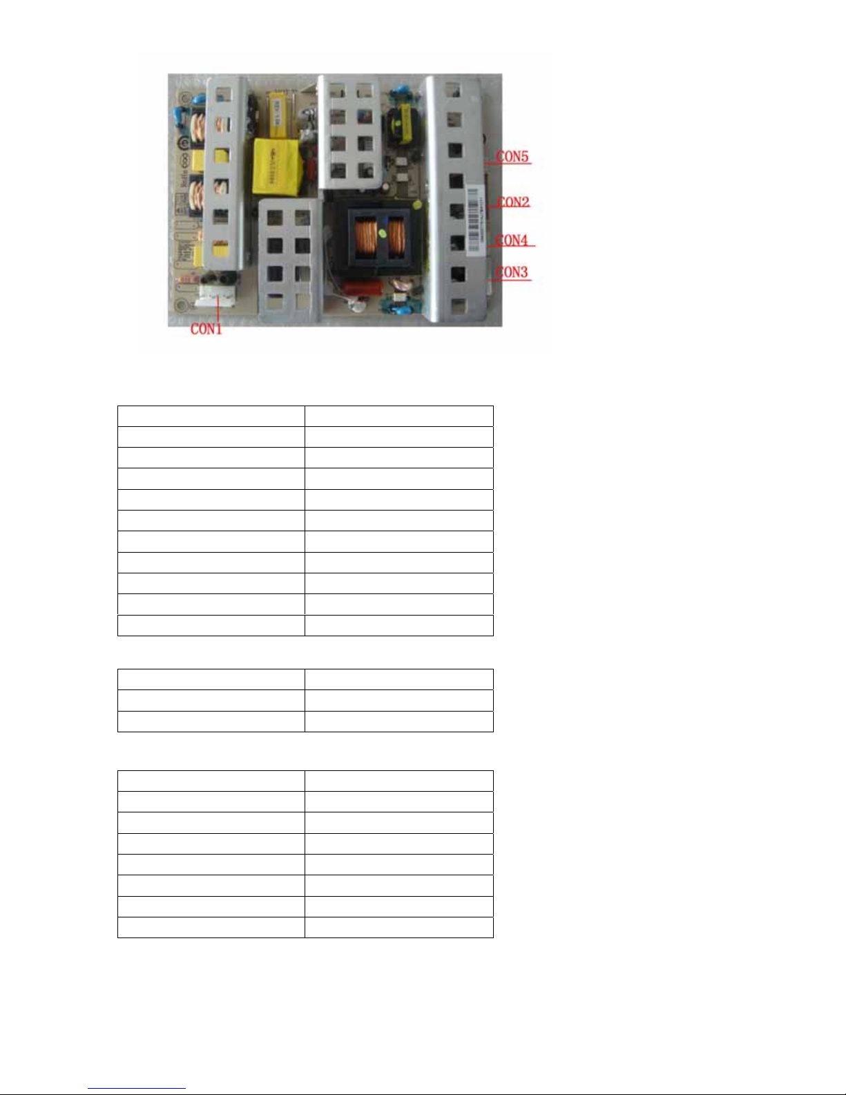
3.3 Power Board
3.3.1 Function Description:
Supply power for Main board,Panel and DC/DC power board
Pin number Signal name Pin number Signal name Pin number Signal name
1 LVDS VDD 9 Not use 17 A1P
2 LVDS VDD 10 Not use 18 A1N
3 LVDS VDD 11 Not use 19 A2P
4 LVDS VDD 12 Not use 20 A2N
5 Not use 13 A0P 21 GND
6 Not use 14 A0N 22 GND
7 GND 15 GND 23 CK1P
8 GND 16 LVDS_SEL 24 CK1N
Pin number Signal name
25 A3P
26 A3N
27 GND
28 GND
29 Not use
30 Not use
Pin number Signal name Description
1 18V Power of Audio power amp
2 18V Power of Audio power amp
3 GND Ground
4 GND Ground
Pin number Signal name
1 L2 L+
3 R4 R+
11
3.3.2 Connector definition
CONNECTOR (CON2)
CONNECTOR (CON4)
CONNECTOR (CON3)
CON2 Signal name
1 24V
2 24V
3 24V
4 24V
5 24V
6 GND
7 GND
8 GND
9 GND
10 GND
CON6 Signal name
1-2 18V
3-4 GND
CON4 Signal name
1 ON/OFF
2 GND
3 5VSB
4 GND
5 GND
6 12V
7

12
3.4 LCD PANEL.
3.4.1 Function Description:
Display the signal.
3.4.2 Connector definition
Pin No Symbol Description Note
1 Power DC 12V
2 Power DC 12V
3 Power DC 12V
4 Power DC 12V
5 Power DC 12V
6 GND GND
7 GND GND
8 GND GND
9 GND GND
10 RO[0]N ODD LVDS SINGAL-
11 RO[0]P ODD LVDS SINGAL+
12 RO[1]N ODD LVDS SINGAL-
13 RO[1]P ODD LVDS SINGAL+
14 RO[2]N ODD LVDS SINGAL-
15 RO[2]P ODD LVDS SINGAL+
16 GND GND
17 ROCLK- ODD LVDS SINGAL-
18 ROCLK- ODD LVDS SINGAL+
19 GND GND
20 RO[3]N ODD LVDS SINGAL-
21 RO[3]P ODD LVDS SINGAL+
22 NC NC
23 NC NC

13
24 GND GND
25 RE[0]P EVEN LVDS SINGAL-
26 RE[0]N EVEN LVDS SINGAL+
27 RE[1]P EVEN LVDS SINGAL-
28 RE[1]N EVEN LVDS SINGAL+
29 RE[2]P EVEN LVDS SINGAL-
30 RE[2]N EVEN LVDS SINGAL+
CND1(Header):S14B-PH-SM4-TB(D)(LF)(JST) or equivalent.
Pin No. Symbol Description
1
2
3
4
5
VBL
+24V Power input
6
7
8
9
10
GND
Ground
11 NC NC
12 BLON BL ON/OFF
13 PWM Internal PWM Control
14 NC NC
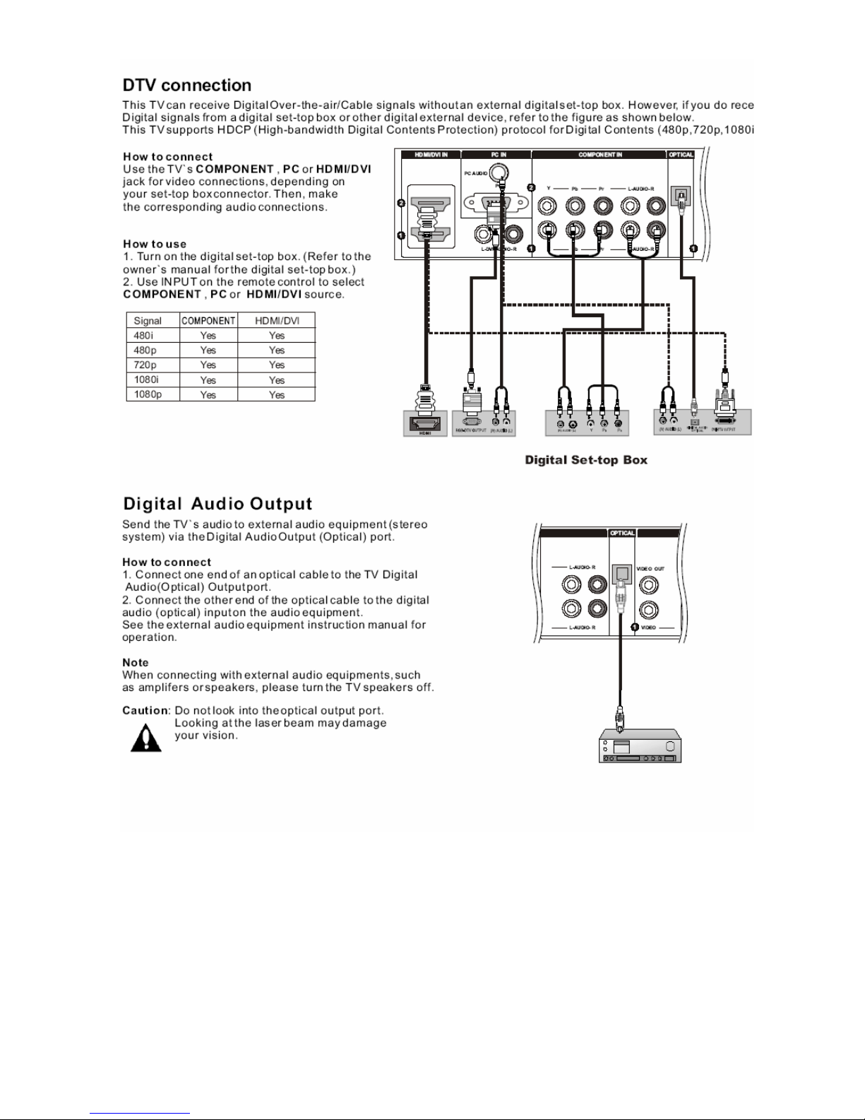
4. INSTALLATION INSTRUCTIONS
4.1 External Equipment Connections
Accessories
Antenna Connection
Generally speaking, to enjoy a clearer picture, we recommend that you use a CATV system or an

14
outdoor antenna . location and antenna positioning.
External Equipment Connections
NOTE: All cables shown are not included with the TV.
Choose Your Connection
There are several ways to connect your television,
depending on the components you want to connect and
the quality of the signal you want to achieve. The
following are examples of some different ways to connect
your TV with different input sources.
VCR connection

15

16
17
 Loading...