

Page 1

SERVICE MANUAL
LCD TV
Model No.
Service No.
Chassis
HL24XP1
HL24XP1A
MTK5380LC-A
WARNING
This service information is designed for experienced repair technicians only and is not designed for use by the general public.
It does not contain warnings or cautions to advise non-technical individuals of potential dangers in attempting to service a product.
Products powered by electricity should be serviced or repaired only by experienced professional technicians. Any attempt to service or repair
the product or products dealt with in this service information by anyone else could result in serious injury or death.
©2009 Qingdao Haier Electronics Co., Ltd.
All rights reserved. Unauthorized copying and distribution is a violation of law.
Haier Group
Page 2

CONTENTS
Chapter 1: General Information
1-1. Document Information
1-2. General Guidelines
1-3. Important Notice
1-3-1. Follow the regulations and warnings ..................................................... 3
1-3-2. Be careful to the electrical shock ........................................................... 3
1-3-3. Electro static discharge (ESD) ...............................................................3
1-3-4. About lead free solder (PbF) .................................................................. 4
8VHWKHJHQHZLQJSDUWVVSHFL¿HGSDUWV .............................................. 4
1-3-6 Safety check after repairment .................................................................4
1-3-7. Ordering Spare Parts .............................................................................6
1-3-8. Photo used in this manual ..................................................................... 6
..................................................................................... 3
1-4. How to Read this Service Manual
1-4-1. Using icons: ........................................................................................... 6
........................................................................... 3
................................................................................ 3
...................................................... 6
&KDSWHU6SHFL¿FDWLRn
6SHFL¿FDWLRQOLVW
2-2 External pictures (four faces)
...................................................................................... 8
.............................................................. 9
Chapter 3. Disassemble and Assemble
3-1 Remove the Pedestal
3-2. Remove the Front Cover
3-3. Remove the LCD Panel
3-4. Remove the Main Board
3-5. Remove the Power Supply Board
3-6. Remove the Speaker
3-7. Remove the Keypad Assembly
3-8. Remove the Remote Control Board
.............................................................................
.....................................................................11
.......................................................................11
......................................................................11
......................................................
.............................................................................
..........................................................12
..................................................
Chapter 4. Location of Controls and Components
4-1. Board Location
4-2. Main Board
4-2-1 Function Description: ............................................................................ 14
&RQQHFWRUGH¿QLWLRQ .............................................................................. 14
...................................................................................... 13
..............................................................................................
11
12
12
12
13
Page 3

4-3. Power Supply Board
4-3-1. Function description:............................................................................ 16
&RQQHFWRUGH¿QLWLRQ ............................................................................ 16
4-4. LCD Panel
.............................................................................................. 16
............................................................................ 16
Chapter 5. Installation Instructions
Chapter 6. Operation Instructions
6-1. Front Panel Controls
6-2. Back Panel Controls
6-3. Setting Up Your Remote Control
............................................................................ 23
............................................................................. 23
........................................................ 23
..........................................
..........................................
Chapter 7. Electrical Parts
7-1. Block Diagram
7-2. Circuit Diagram
7-3 .Wiring Connection Diagram
....................................................................................... 25
.....................................................................................
............................................................... 41
Chapter 8. Measurements and Adjustments
8-1. Service Mode
8-1-1.How to enter into Service Mode............................................................ 42
8-1-2.How to exit ............................................................................................ 42
8-2. Measurements and Adjustments
8-2-1. Version, S/N, Panel Resoution ............................................................ 42
8-2-2. Video .................................................................................................... 43
8-2-3. Audio .................................................................................................... 44
8-2-4. Channel ............................................................................................... 44
8-2-5. Gamma ................................................................................................ 56
8-2-6. Backlight ..............................................................................................56
8-2-7. Function ............................................................................................... 57
....................................................................................... 42
...................................................... 42
18
23
26
Chapter 9. Trouble shooting
9-1. Simple check
9-2. Power Supply Board Failure Check.
9-3. Mainboard Failure Check
9-4. Pannel Failure
......................................................................................... 49
.................................................................. 51
....................................................................................... 52
................................................ 50
Page 4
Service Manual
Model No.: HL24XP1
Chapter 1: General Information
1-1. Document Information
Document format: Adobe PDF
Author: Zhou Peng
Compiler: Bao Qinghong
1-2. General Guidelines
When servicing, observe the original lead dress. If a short circuit is found, replace all parts which
have been overheated or damaged by the short circuit.
After servicing, see to it that all the protective devices such as insulation barriers, insulation papers
shields are properly installed.
After servicing, make the following leakage current checks to prevent the customer from being
exposed to shock hazards.
1) Leakage Current Cold Check
2) Leakage Current Hot Check
3) Prevention of Electro Static Discharge (ESD) to Electrostatically Sensitive
1-3. Important Notice
1-3-1. Follow the regulations and warnings
Most important thing is to list up the potential hazard or risk for the service personnel to open
the units and disassemble the units. For example, we need to describe properly how to avoid the
possibility to get electrical shock from the live power supply or charged electrical parts (even the
power is off).
This symbol indicates that high voltage is present inside.It is dangerous to make any
king of contact with any inside part of this product.
This symbol indicates that there are important operating and maintenance instructions
in the literture accompanying the appliance.
1-3-2. Be careful to the electrical shock
7RSUHYHQWGDPDJHZKLFKPLJKWUHVXOWLQHOHFWULFVKRFNRU¿UHGRQRWH[SRVHWKLV79VHWWRUDLQ
or excessive moisture. This TV must not be exposed to dripping or splashing water, and objects
¿OOHGZLWKOLTXLGVXFKDVYDVHVPXVWQRWEHSODFHGRQWRSRIRUDERYHWKH79
1-3-3. Electro static discharge (ESD)
Some semiconductor (solid state) devices can be damaged easily by static electricity. Such
3
Page 5

Service Manual
Model No.: HL24XP1
components commonly are called Electrostatically Sensitive (ES) Devices. The following
WHFKQLTXHVVKRXOGEH XVHG WR KHOSUHGXFH WKH LQFLGHQFHRI FRPSRQHQW GDPDJH FDXVHGE\
electros static discharge (ESD).
Electrostatically Sensitive (ES) Devices
Some semiconductor (solid-state) devices can be damaged easily by static electricity. Such
components commonly are called Electrostatically Sensitive (ES) Devices. Examples of typical
ES devices are integrated circuits and some field-effect transistors and semiconductor "chip"
FRPSRQHQWV7KHIROORZLQJWHFKQLTXHVVKRXOGEHXVHGWRKHOSUHGXFHWKHQFLGHQFHRIFRPSRQHQW
damage caused by static by static electricity.
,PPHGLDWHO\ EHIRUH KDQGOLQJ DQ\ VHPLFRQGXFWRU FRPSRQHQW RU VHPLFRQGXFWRUHTXLSSHG
assembly, drain off any electrostatic charge on your body by touching a known earth ground.
Alternatively, obtain and wear a commercially available discharging wrist strap device, which
should be removed to prevent potential shock reasons prior to applying power to the unit under
test.
$IWHUUHPRYLQJDQHOHFWULFDODVVHPEO\HTXLSSHGZLWK(6GHYL FHV SODFHWKHDVVHPEO\ RQD
conductive surface such as aluminum foil, to prevent electrostatic charge buildup or exposure of
the assembly.
1-3-4. About lead free solder (PbF)
This product is manufactured using lead-free solder as a part of a movement within the
consumer products industry at large to be environmentally responsible. Lead-free solder must be
used in the servicing and repairing of this product.
8VHWKHJHQHZLQJSDUWVVSHFL¿HGSDUWV
6SHFLDOSDUWVZKLFKKDYHSXUSRVHVRI¿UHUHWDUGDQWUHVLVWRUVKLJKTXDOLW\VRXQG FDSDFLWRUV
low noise (resistors), etc. are used.
:KHQUHSODFLQJDQ\RIFRPSRQHQWVEHVXUHWRXVHRQO\PDQXIDFWXUHVVSHFL¿HGSDUWVVKRZQLQ
the parts list.
Safety Component
Ɣ&RPSRQHQWVLGHQWL¿HGE\PDUNKDYHVSHFLDOFKDUDFWHULVWLFVLPSRUWDQWIRUVDIHW\
1-3-6 Safety check after repairment
&RQ¿UPWKDWWKHVFUHZVSDUWVDQGZLULQJZKLFK ZHUHUHPRYHGLQRUGHUWRVHUYLFHDUHSXWLQWKH
original positions, or whether there are the positions which are deteriorated around the serviced
places serviced or not. Check the insulation between the antenna terminal or external metal and
the AC cord plug blades. And be sure the safety of that.
General Servicing Precautions
4
Page 6

Service Manual
Model No.: HL24XP1
1. Always unplug the receiver AC power cord from the AC power source before:
a. Removing or reinstalling any component, circuit board module or any other receiver
assembly.
b. Disconnecting or reconnecting any receiver electrical plug or other electrical connection.
c. Connecting a test substitute in parallel with an electrolytic capacitor in the receiver.
CAUTION:
may result in an explosion hazard.
2. Test high voltage only by measuring it with an appropriate high voltage meter or other voltage
PHDVXULQJGHYLFH'90)(7920HWFHTXLSSHGZLWKDVXLWDEOHKLJKYROWDJHSUREH
Do not test high voltage by "drawing an arc".
3. Do not spray chemicals on or near this receiver or any of its assemblies.
4. Unless specified otherwise in this service manual, clean electrical contacts only by applying
the following mixture to the contacts with a pipe cleaner, cotton-tipped stick or comparable nonabrasive applicator; 10% (by volume) Acetone and 90% (by volume) isopropyl alcohol (90%-99%
strength).
CAUTION:
8QOHVVVSHFL¿HGRWKHUZLVHLQWKLVVHUYLFHPDQXDOOXEULFDWLRQRIFRQWDFWVLVQRWUHTXLUHG
Capacitors may result in an explosion hazard.
5. Do not defeat any plug/socket B+ voltage interlocks with which receivers covered by this
VHUYLFHPDQXDOPLJKWEHHTXLSSHG
A wrong part substitution or incorrect polarity installation of electrolytic capacitors
7KLVLVDÀDPPDEOHPL[WXUH
6. Do not apply AC power to this instrument and/or any of its electrical assemblies unless all
solid-state device heat sinks are correctly installed.
7. Always connect the test receiver ground lead to the receiver chassis ground before connecting
the test receiver positive lead.
Always remove the test receiver ground lead last. Capacitors may result in an explosion
hazard.
8VHZLWKWKLVUHFHLYHURQO\WKHWHVW¿[WXUHVVSHFL¿HGLQWKLVVHUYLFHPDQXDO
CAUTION:
9. Remove the antenna terminal on TV and turn on the TV.
10. Insulation resistance between the cord plug terminals and the eternal exposure metal should
be more than Mohm by using the 500V insulation resistance meter.
,IWKHLQVXODWLRQ UHVLVWDQFH LV OHVV WKDQ 0RKPWKH LQVSHFWLRQ UHSDLU VKRXOG EHUHTXLUHG
If you have not the 500V insulation resistance meter, use a Tester. External exposure metal:
Antenna terminal Headphone jack.
'RQRWFRQQHFWWKHWHVW¿[WXUHJURXQGVWUDSWRDQ\KHDWVLQNLQWKLVUHFHLYHU
5
Page 7

Service Manual
Model No.: HL24XP1
3. Use only a grounded-tip soldering iron to solder or unsolder ES devices.
4. Use only an anti-static type solder removal device. Some solder removal devices not
FODVVL¿HGDVDQWLVWDWLFFDQJHQHUDWHHOHFWULFDOFKDUJHVVXI¿FLHQWWRGDPDJH(6GHYLFHV
5. Do not use freon-propelled chemicals. These can generate electrical charges sufficient to
damage ES devices.
6. Do not remove a replacement ES device from its protective package until immediately before
you are ready to install it.
(Most replacement ES devices are packaged with leads electrically shorted together by
conductive foam, aluminum foil or comparable conductive material).
7. Immediately before removing the protective material from the leads of a replacement ES
device, touch the protective material to the chassis or circuit assembly into which the device will
be installed.
CAUTION:
precautions.
8. Minimize bodily motions when handling unpackaged replacement ES devices. (Otherwise
harmless motion such as the brushing together of your clothes fabric or the lifting of your foot
IURPDFDUSHWHGÀRRUFDQJHQHUDWHVWDWLFHOHFWULFLW\VXI¿FLHQWWRGDPDJHDQ(6GHYLFH
Be sure no power is applied to the chassis or circuit, and observe all other safety
1-3-7. Ordering Spare Parts
Please include the following informations when you order parts. (Particularly the Version letter)
1. Model number, serial number and software version
The model number and serial number can be found on the back cover of each product. Software
version can be found in the Spare Parts List.
2. Spare part No. and description
Spare part No. and description can be found in the Spare Parts List.
1-3-8. Photo used in this manual
The illustration and photos used in this Service Manual may not base on the final design of
products, which may differ from your products in some way.
1-4. How to Read this Service Manual
1-4-1. Using icons:
,FRQVDUHXVHGWRDWWUDFWWKHDWWHQWLRQRIWKHUHDGHUWRVSHFL¿FLQIRUPDWLRQ7KHPHDQLQJRIHDFK
icon is described in the table below:
Note:
A “note” provides information that is not indispensable, but may nevertheless be
valuable to the reader, such as tips and tricks.
6
Page 8

Caution:
A “caution” is used when there is danger that the reader, through incorrect
PDQLSXODWLRQPD\GDPDJHHTXLSPHQWORRVHGDWDJHWDQXQH[SHFWHGUHVXOWRU KDVWR
restart(part of) a procedure.
Warning:
A “warning” is used when there is danger of personal injury.
Reference:
A “reference” guides the reader to other places in this binder or in this manual, where
Service Manual
Model No.: HL24XP1
KHVKHZLOO¿QGDGGLWLRQDOLQIRUPDWLRQRQDVSHFL¿FWRSLF
7
Page 9

Service Manual
Model No.: HL24XP1
&KDSWHU6SHFL¿FDWLRQ
6SHFL¿FDWLRQOLVW
Model HL24XP1
Screen Size 23.6 inch
Aspect Ratio 16:9
Resolution 1920x1080
Response Time (ms)
Angel of View H:170/V:60
Color Display 16777216
No. of Preset Channels 181
OSD Language
Color System NTSC
Audio System M, BG, I, L, L'
Audio Output Power
(Built-in) (W)
Audio Output Power
(outer) (W)
Total Power Input (W) 60W
Voltage Range (V) AC100V~240V
3RZHU)UHTXHQF\+] 60Hz
Time of Sleep Timer
(MINS)
5 (GRAY TO
GRAY)
English/French/Spanish
3W×2
No
120Min
Net Weight (KG) 6.0
Gross Weight (KG) 7.0
Net Dimension (MM) 600x160x500
Packaged Dimension
(MM)
8
655x170x520
Page 10
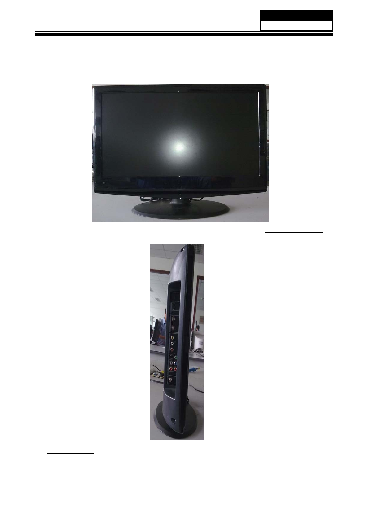
2-2 External pictures (four faces)
Service Manual
Model No.: HL24XP1
Front Side
Left Side
9
Page 11
Service Manual
Model No.: HL24XP1
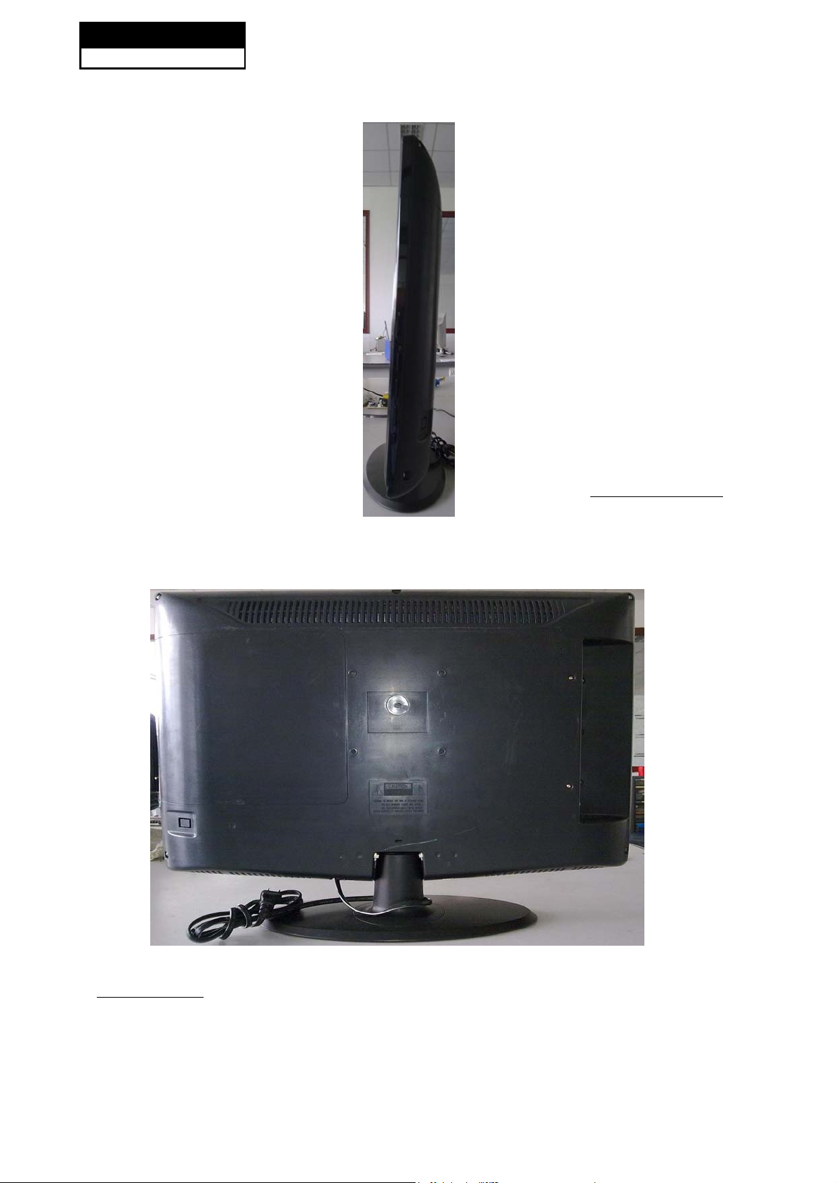
Right Side
10
Back Side
Page 12
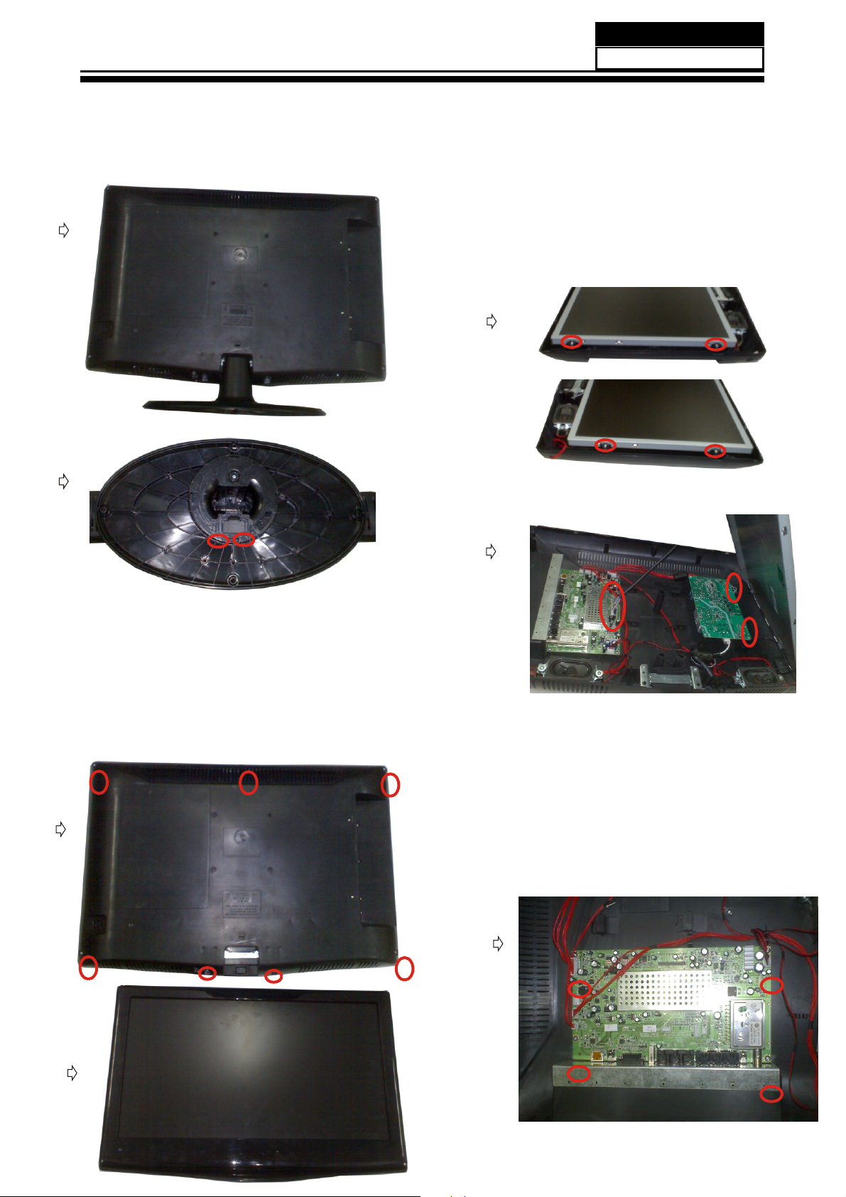
Chapter 3. Disassemble and Assemble
.
3-1 Remove the Pedestal
①
Service Manual
Model No.: HL24XP1
①
Remover the eight screw indicated with ○
②.
Turn to front cover upwards
③
Then remove the front cover from the unit
3-3. Remove the LCD Panel
①
②
① Lay down the unit so that rear cover
downward.
Remove the two screw from the
②
pedestal indicated with③ ○.
Then remove the pedestal .
3-2. Remove the Front Cover
①
②
①Remover the six screw indicated with ○.
②Remover the pin indicated with ○.
③Then remove the panel.
3-4. Remove the Main Board
②
①
11
Page 13
Service Manual
Model No.: HL24XP1
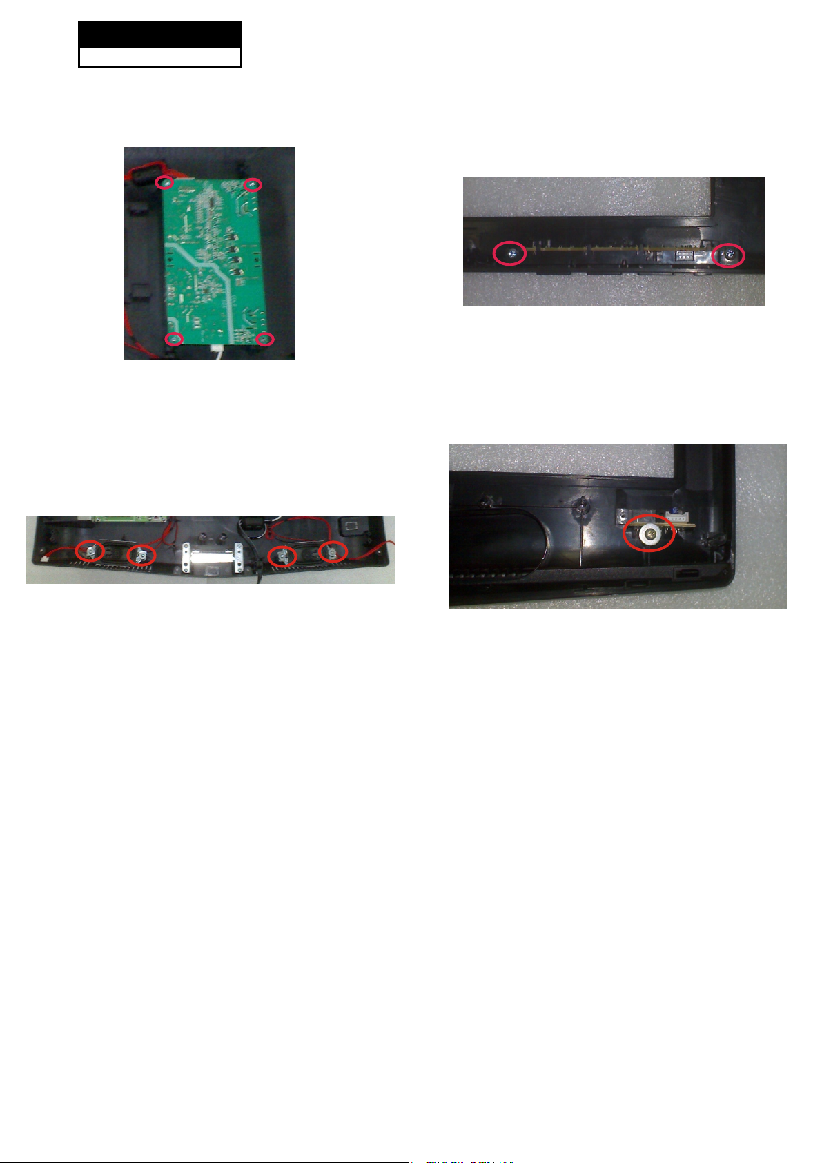
3-5. Remove the Power Supply Board
①Remover the four screw indicated with ○.
②Then remove the P ower Board.
3-6. Remove the Speaker
3-7. Remove the Keypad Assembly
①
Remover the two screw indicated with ○.
②Then remove the K eypad Assembly.
3-8. Remove the Remote Control Board
l
①Remover the four screw indicated with ○.
②Remover Sponge piece
③
Then remove the . Speaker
①Remover the one screw indicated with ○.
②Then remove the R emote Control Board .
12
Page 14
Service Manual
Model No.: HL24XP1
Chapter 4. Location of Controls and Components
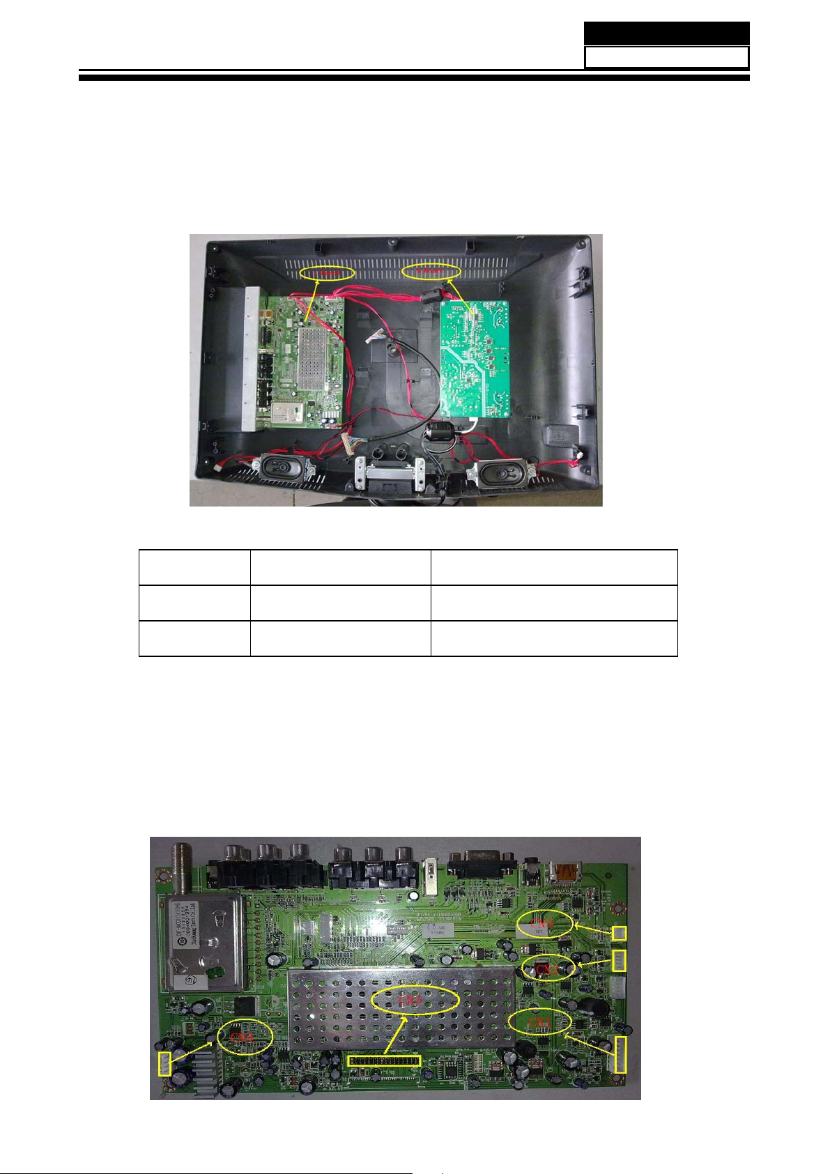
4-1. Board Location
No. Parts number Description
A BoardDC18E0E0200MMain Board
B Board BPower Supply Board
4-2. Main Board
13
Page 15

Service Manual
Model No.: HL24XP1
4-2-1 Function Description:
Main Board
3URFHVVVLJQDOZKLFKLQFHSWIURPH[WHULRUHTXLSPHQWWKHQWUDQVODWHLQWRVLJQDOWKDWSDQHOFDQGLVSOD\
&RQQHFWRUGH¿QLWLRQ
Main board connector
Power connectors (CN1)
CN1
Pin number Signal name
1 +12V
2 +12V
3BL
4 DIM
5 GND
6 GND
7SW
Notes:
CN1-Pin 3: Backlight on/off:
The system can turn on or turn off the backlight of TFT LCD Panel through the power supply
unit path.
System board will use this pin to control system power.
CN1-Pin 4: Control the luminance of backlight
The system can generate the PWN signal to control the strength of TFT LCD Panel’s
backlight through this connector
Keypad and remote connector (CN2,CN3)
CN2 CN3
Pin number
1
2
3
4
5
Speaker Connector (CN4)
Signal name Pin number
SB5V 1
IR 2
LED_R 3
LED_G
GND
Signal name
GND
AD1
AD2
Pin number Signal name
1L+
2L3R4R+
14
Page 16
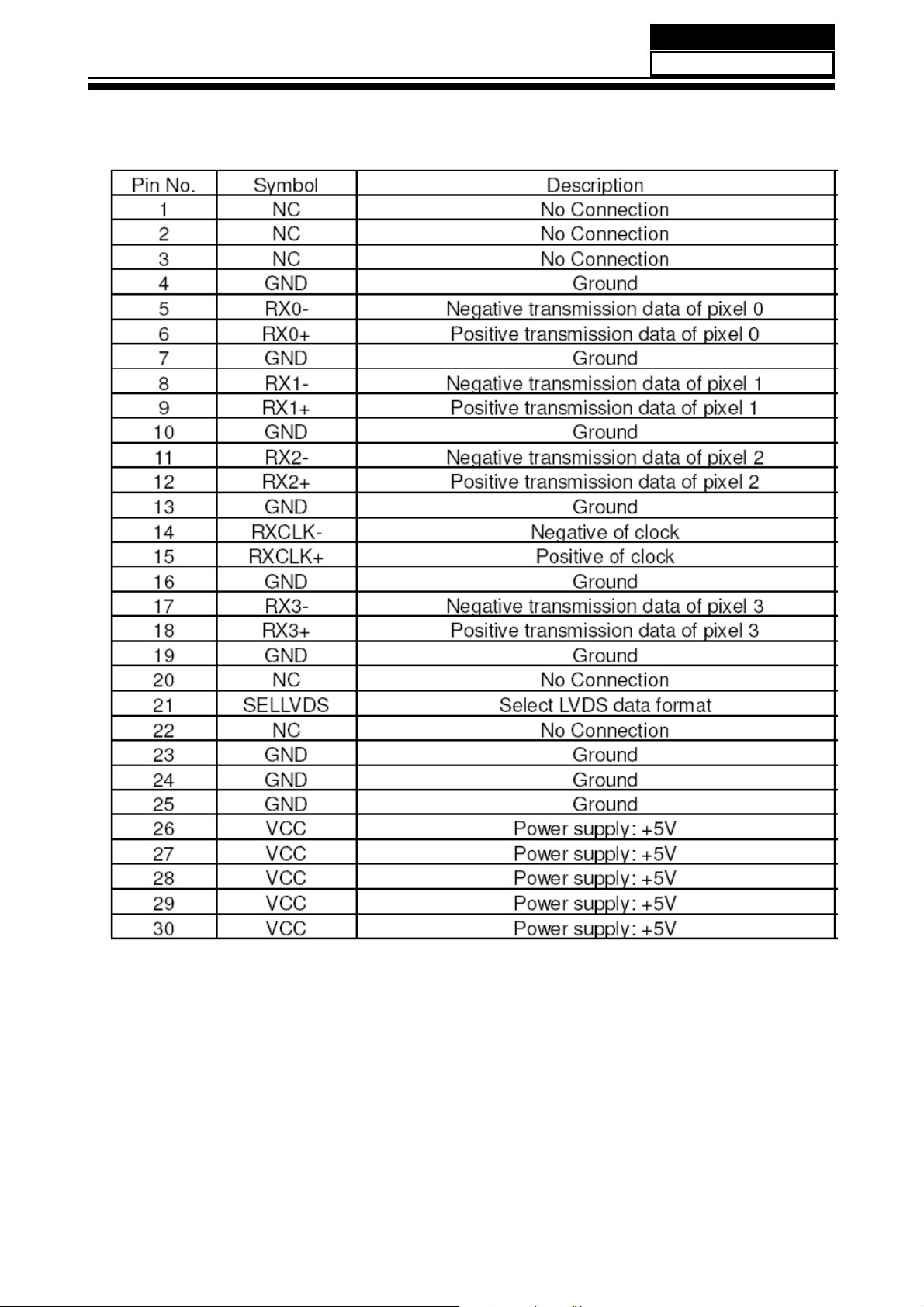
LVDS Connector (CN5)
Service Manual
Model No.: HL24XP1
Pin number
1 NC NC
2 NC NC
3 NC NC
4 NC NC
5 LVDS_D0E_N LVDS EVEN 0 - Signal
6 LVDS_D0E_P LVDS EVEN 0 + Signal
7 GND Ground
8 LVDS_D1E_N LVDS EVEN 1 - Signal
9 LVDS_D1E_P LVDS EVEN 1 + Signal
10 GND Ground
11 LVDS_D2E_N LVDS EVEN 2 - Signal
12 LVDS_D2E_P LVDS EVEN 2 + Signal
13 GND Ground
14 LVDS_CE_N LVDS EVEN Clock - Signal
15 LVDS_CE_P LVDS EVEN Clock + Signal
16 GND Ground
17 LVDS_D3E_N LVDS EVEN 3 - Signal
18 LVDS_D3E_P LVDS EVEN 3 + Signal
19 GND Ground
20 NC NC
21 NC NC
22 NC NC
23 GND Ground
24 GND Ground
25 GND Ground
26 Panel_power Power for panel
27 Panel_power Power for panel
28 Panel_power Power for panel
29 Panel_power Power for panel
30 Panel_power Power for panel
Signal name Description
15
Page 17

Service Manual
˄
Model No.: HL24XP1
4-3. Power Supply Board
4-3-1. Function description:
To supply power for Mainboard, Panel.
&RQQHFWRUGH¿QLWLRQ
INPUT CONNECTOR (CNC1)
Power supply and Inverter Connector
CNC1˅
Pin
number Signal name Description
1&
*1'
*1'
%/$'-867 ,19(57(5/LJKWQHVV$GMXVW
%/212)) ,19(57(56ZLWFK&RQWURO
9 9 Power
9 9
Other Connector
AC120V~AC240V Input (CNC2)
Power supply for panel (CNC3)
Power supply for panel (CNC4)
Power supply for panel (CNC5)
Power supply for panel (CNC6)
4-4. LCD Panel
Ground
Ground
Power
16
Page 18
Panle LVDS Connector (CNC3)
Service Manual
Model No.: HL24XP1
17
Page 19

Service Manual
Model No.: HL24XP1
Chapter 5. Installation Instructions
Antenna Connection
Connect one end of a coaxial cable (not included) to the ANT IN jack on the back of your TV/DVD
combo, then connect the other end of the cable into the antenna or cable TV wall outlet.
To improve picture quality from an antenna in a poor signal area, install a signal amplifier.
If you need to split the antenna signal to connect two TVs, install a two-way splitter.
Choose Your Connection
There are several ways to connect your television, depending on the components you want to
connect
and the quality of the signal you want to achieve. The following are examples of some different
ways to connect your TV with different input sources. Choose the connection which is best for you.
18
Page 20

Service Manual
VGA Setup
You can use your LCD-TV as a monitor for your personal computer using a VGA
cable (not supplied).
Connection and use steps:
1.Read the user guide supplied with
your computer and ensure that it has
a VGA connector;
2.Make sure that the power of the LCD
-TV and the PC are off;
3.Connect a D type 15-pin PC interface
cable ( not supplied ) to the PC video
interface connector on the PC. Then
connect the other end to the PC video
interface connector on the back of the
LCD-TV.Tighten the screws on the PC
connectors once they are firmly
connected;
4.Turn on the power of the LCD-TV first ,
and then turn on the power of the PC;
5.Press INPUT button to set the video input mode of the LCD-TV to PC;
Once the input for PC is selected and if you see no image press function
F8 on you pc.
6.Check the image on your TV. There may be noise associated with the resolution,
vertical pattern, contrast or brightness in PC mode. If noise is present, change
the PC mode to another resolution, change the refresh rate to another rate or
adjust the brightness and contrast on the menu until the picture is clear. If the
refresh rate of the PC graphic card can not be changed, change the PC graphic
card or consult the manufacturer of the PC graphic card.
Resolution
Mode
VGA
SVGA
XGA
Resolution
640x480
800x600
1024x768
Line frequency(KHz)
31.5
37.9
48.4
VGA IN
PC AUDIO IN
Frame frequency(Hz)
60
60
60
Model No.: HL24XP1
Note: All above listed are subject to VESA criteria.
Component Setup
How to connect
Connect the DVD video outputs (Y, PB, PR)
to the Component(Y, Pb, Pr) IN jacks on
the TV and connect the DVD audio outputs
to the AUDIO IN jacks on the TV, as shown
in the figure.
NOTE: If your DVD player does not have
component video output,use S-Video.
How to use
1. Turn on the DVD player, insert a DVD.
INPUT
2. Use button on the remote
control to select the proper input.
Pr Pb Y
COMPONENT IN
R-AUDIO-L
S-VIDEO IN
19
Page 21

Service Manual
Model No.: HL24XP1
Cable TV Setup
After subscribing to a cable TV service from a local provider you can watch cable
TV programming. The TV cannot display TV programming unless a TV tuner
device or cable TV converter box is connected to the TV.
For further information regarding cable TV service, contact your local cable TV
service provider(s).
Connection Option 1
1. Select 3 or 4 with channel switch on cable
box.
2. Tune the TV channel to the same selected
output channel on cable box.
3. Select channels at the cable box or with
the cable box remote control.
Connection Option 2
1. Connect the audio and video cables from
the Cable Box's output jacks to the TV
input jacks, as shown in the figure.When
connecting the TV to a Cable Box, match
the jack colors
(Video = yellow, Audio Left = white, and
Audio Right = red).
2. Select the input source by using the
button on the remote control.
INPUT
3. Select your desired channel with the
remote control for cable box.
ATN IN R-AUDIO-L R-AUDIO IN-L
Pr Pb Y
COMPONENT IN
S-VIDEO IN
VIDEO
External Component Source Setup
How to connect
Connect the audio and video cables from
the external equipment's output jacks to the
TV input jacks, as shown in the figure.
When connecting the TV to external equipment, match the jack colors (Video = yellow,
Audio Left = white, and Audio Right = red).
How to use
1. Select the input source by using the
button on the remote control.
2. Operate the corresponding external equi pment. Refer to external equipment ope rating guide.
INPUT
R-AUDIO IN-L VIDEO
HDMI Connections
When the source device(DVD player or Set Top Box) supports HDM
How To Connect
1. Connect the source device to HDMI port of this TV with an HDMI cable(not supplied with this
product).
2. No separated audio connection is necessary.
20
Page 22

Service Manual
Model No.: HL24XP1
How To Use
If the source device supports Auto HDMI function, the output resolution of the source device will be
automatically
set to 1280x720p.
If the source device does not support Auto HDMI, you need to set the output resolution
appropriately.
To get the best picture quality, adjust the output resolution of the source device to 1280x720p.
Select HDMI input source in input source option of Select Main source menu.
When the source device(DVD player or Set Top Box) supports DVI
How To Connect
1. Connect the source device to HDMI port of this TV with a HDMI-to-DVI cable(not supplied with
this product).
2. A separated audio connection is necessary.
3. If the source device has an analog audio output connector, connect the source device audio
output to DVI Audio
In port located on the
left side of HDMI port.
How To Use
If the source device supports Auto DVI function, the output resolution of the source device will be
automatically
set to 1280x720p.
If the source device does not support Auto DVI, you need to set the output resolution appropriately.
To get the best picture quality, adjust the output resolution of the source device to 1280x720p.
Press the INPUT button to select HDMI input source in input source option of Select Main source
menu.
Installation
Cable sample
HDMI Cable
(not supplied with the product)
HDMI to DVI Cable
( not supplied with the product)
21
Page 23

Service Manual
Model No.: HL24XP1
Analog Audio Cable
(Stereo to RCA type)
(not supplied with the product)
Connecting Headphones
You can connect a set of headphones to your set if you wish to watch a
TV programmer without disturbing the other people in the room.
Plug a set of headphones into the 3.5mm
mini-jack socket on the rear panel of the set.
LR
YPbPr
Audio In
Headphone
out
S-VID EO
Note˖
Ƶ Prolonged use of headphones at a high volume
may damage your hearing.
Ƶ You will not receive sound from the speakers
when you connect headphones to the system.
Power source
Wider Hole
and Blade
Polarized AC Cord Plug
22
AC Outlet
TO USE AC POWER SOURCE
Use the AC polarized line cord provided for operation on AC.
Insert the AC cord plug into a standard polarized AC outlet.
NOTES:
Ƶ Never connect the AC line cord plug to other than the specified voltage.
Use the attached power cord only.
Ƶ If the polarized AC cord does not fit into a non-polarized AC outlet,
do not attempt to file or cut the blade. It is the user`s responsibility to have an
electrician replace the obsolete outlet.
Ƶ If you cause a static discharge when touching the unit and the unit fails to
function, simply unplug the unit from the AC outlet and plug it back in. The unit
should return to normal operation.
Page 24

6. Operation Instructions
Service Manual
Model No.: HL24XP1
6-1 Front panel controls
Control Panel Function
1. POWER Press to turn on and off the TV.
2. INPUT Selects the input si gnals.
3. MENU Menu display. Press to access the on-screen menu display.
4. VOL- Volume down / Left button to adjust the item in the OSD.
VOL+ Volume up / Right button to adjust the item i n the OSD
/Press to enter.
5. CH- TV channe
CH+ TV channel up / to select the item in the menu.
6. Power indi cator
7. Remote Sensor Receivers IR signals from the remote control.
Do not put anything near the sensor ,which may
block the remote control signal.
INPUT MENU VOL- VOL+ CH- CH+ POWER
R1 series series F series K1 1
l down / to sel ect the item in the menu.
6-2 Back panel controls
ATN IN R-AUDIO-LR-AUDIO IN-L
1.ANT IN(Antenna Input) Connect cable or antenna signals to the TV, either
dir ectly or through your cable box.
2.Headphone jack : Headphone audio output ter minal.
3.Audio in Connect audio output from an exter nal device to these jacks.
4.S-VIDEO Connect S-V ideo out from an S-V ideo device to the jacks.
5.Audio in Connect audio output from an exter nal device to these jacks.
6.Video in Connect video output from an exter nal device to this jack.
7.USB input Connect a USB flash drive to view JPEG images or listen to MP3
songs.
8.VGA Connect to the VGA 15P IN analog output connector of a PC
gr aphics car d to use set as a
9.PC audio in C onnect the audio output from the pc to the PC audio input port.
10. HDMI: Connect a HDMI device to r eceive digital audio and uncompressed
digital video.
11. Component Input Connect a component video device to these jacks.
Pr Pb Y
S-VIDEO IN
COMPONENT IN
6-3 Setting Up Your Remote Control
VIDEO
PC display.
VGA INUSBHDMI
PC AUDIO IN
After it has been set up properly, your remote control can operate in six different modes:
TV, VCR, CABLE, DVD, SETBOX or AUDIO. Pressing the corresponding button on the remote
control
23
Page 25

Service Manual
Model No.: HL24XP1
Remote Control Key Functions
When using the remote control, aim it
towards the remote sensor on the TV
1
2
3
4
5
6
7
8
9
10
11
12
13
14
15
16
17
18
19
20
USB
GUIDE
PICTURE AUDIOARCFAVO R ITE
MUTE
MENU
SLEEPDISPLAY
OPEN/CLOSE
REV
D.M ENU
SEARCH
CCD MTS/SAP CH.L IST
INPUT
VOL CH
ENTER
PLAY/PAUS E
D.CALL
ANGLE
(For TV wit h DVD)
RECALL
STOP REPE AT
PREV NEXT
SETUP
D.AUDI O
SUBTI TLE
PROGRAM
DVD
EXIT
1.Press to turn on and off the TV
2.Press to switch input source to USB in
3.Display the guide when you are watching analog or
digital channels
21
4.Select a closed caption
22
5.Press repeatedly to cycle through the available picture
23
modes
24
25
6.Press to cycle through different sound settings
7.Show the input source
8.Switches the video sound on or off
9.Press to adjust the volume
26
10.Press to open the on-screen menu
11.Thumbstick(Up/Down/Left/Right)
Allows you to navigate the on-screen menus
and adjust the system settings to your preference.
27
12.Press to display the sleep timer option
28
13.DVD PLAY/PAUSE
14.DVD Open/close
15.
29
DVD FAST FORWARD
16.DVD FAST REVERSE
17.DVD CALL
30
18.DVD MENU
19.DVD SEARCH
20.DVD ANGLE
31
21.Press to switch input source to DVD in
22.Open the channel list in TV
23.Select MONO, STEREO, SAP in NTSC system
24.Open the favourite channel list in TV
32
25.Press to change the aspect ratio
33
26.Press to change a channel
34
27.Press to select digital channels. For example, to enter
35
“54-3”, press “54”, “ ” and “3”
36
37
28.Press to jump back and forth b
38
29.Press to scan through channels. To scan quickly
39
between the last two channels, press and hold down
40
either +/- .
etween two channels
30.Exit On Screen Display
31.Accesses the highlighted item in the on-screen menu
32.Press to display the TV status information on the top
of the TV screen
33.DVD STOP
34.DVD REPEAT
35.DVD Previous Chapter
36.DVD Next Chapter
37.DVD AUDIO Mode
38.DVD SETUP
39.DVD PROGRAM
40.DVD SUBTITLE
LEFT
UP
RIGHT
DOWN
24
Page 26

Chapter 7. Electrical Parts
7-1. Block Diagram
HDMI1
Service Manual
Model No.: HL24XP1
USB
YPbPr
S-Video
tuner
Composite
YPbPr
Composite
L/R
VGA(P11)L/R
VGA
MT 5 3 8 0
LC
Main IC
I2C Bus
EEPROM
TDA1517
LVDS
DDR
Flash
P
A
N
E
L
25
Page 27

Service Manual
Model No.: HL24XP1
7-2. Circuit Diagram
GND
+3V3SB
+5VSB
+12V
OPWRSB
+5V
OIRI
OPCTRL3
ADIN2
ADIN1
E
J1
D
DATE
Note
C
History
IR_IN
+3V3SB2,4,7,8,9,13
IR_IN10
OPWRSB4
+12V3,9,14,15
+5V2,3,5,8,9,10,14,15
+5VSB2,10,11,15
GND2,3,4,5,6,7,8,9,10,11,12,13,14,15
1234567
2007/04/09
2007/06/11
2007/06/11
GPIO_3
DVD_5V
OPCTRL34
EMI/HAIERJ1EMI
EMI/HAIER
TP15TP15
ADIN24
ADIN14
GPIO_34
DVD_5V
TP92TP92
OIRI7
EMI
8
Speaker
MT5380
LQFP
DVD_5V
TP93TP93
TP94TP94
TP23
TP23
TEST COPPER
TEST COPPER
123
CNE2
CNE2
U13
TP77
TP77
+5VSB
ADIN2_K1
ADIN1_K0
CNA4
CNA4
TEST COPPER
TEST
TEST COPPER
TEST
TP78
TP78
TP79
TP79
4
PH-4H
PH-4H
MT8292
FB
FB
C0805/SMD
C0805/SMD
FB10
FB10
+5V
TEST COPPER
TEST COPPER
TEST
TEST
TEST
TEST
TEST COPPER
TEST COPPER
SIP-4P-2.0A
SIP-4P-2.0A
Tuner,U22
R,L V_OUT L,R
GND3+5V4STB5+12V1GND
2
FB11
FB11
+12V
R330R0603/SMD
R330R0603/SMD
GPIO_3
TEST
TEST
L,R
AV1R,L
SPDIF
HPL,R
YC1
FB
C0805/SMD
FB
C0805/SMD
5PIN_2.0
5PIN_2.0
TP89TP89
TP91TP91
TP90TP90
2N3904
SOT23/SMD
2N3904
SOT23/SMD
3 2
OR
R0603/SMD
R0603/SMD
Q53
Q53
10k
R0603/SMD
10k
R0603/SMD
1
R170910k
R170910k
R0603/SMD
R0603/SMD
OPCTRL3
INPUT1R
INPUT1L
INPUT0R
INPUT0L
3 2
2N3904
2N3904
SOT23/SMD
SOT23/SMD
AR2
AL2
AR1
AL1
AL1,AR1
AIN0L,R
AIN1L,R
TP87TP87
TP88TP88
AL2,AR2
MT5380
AIN2L,RYPBPR0L,R_IN
AIN3L,R
+5VSB
+12V
+5VSB
+5VSB
TP20
TP20
+3V3SB
CNA1
CNA1
TEST
TEST
20k
20k
R398
R398
R47NCR0603/SMD
R47NCR0603/SMD
TP29
TP29
R0603/SMD
R0603/SMD
NC/2N3904
NC/2N3904
Q2
Q2
1
R9
R9
NC\4.7K
NC\4.7K
NC
R0603/SMD
NC
R0603/SMD
R1620
R1620
1234567
CE639
CE639
SOT23/SMD
SOT23/SMD
3 2
R0603/SMD
R0603/SMD
Q27
Q27
TEST
TEST
TJC3-7A
SIP-7P-2.5
TJC3-7A
SIP-7P-2.5
+
+
R8
R8
0
0
R4024.7K
R4024.7K
OPWRSB
+5V
470uF/16v
470uF/16v
2N3904
2N3904
1
R0603/SMD
R0603/SMD
CN7CN7
䕧ܹ
5V&12V
C470UF16V/D10H9
C470UF16V/D10H9
TP3
TP3
TEST
TEST
R0603/SMD
R0603/SMD
SOT23/SMD
SOT23/SMD
3 2
C3
0.1uF
C0402/SMDC30.1uF
C0402/SMD
47K
R0603/SMD
47K
R0603/SMD
R403
R403
1
2
GND
Open Frame
24V in
+5V
+5VSB
C701
C701
CE641
+
E10
E10
+
+
0.1uF
0.1uF
1 2
470uF/16V+CE641
470uF/16V
220uF/16V
220uF/16V
E
OIRI
R1694100R
R1694100R
R0603/SMD
R0603/SMD
D2
D2
12
IR_IN
TP22
TP22
TEST
TEST
LED_GRE#
LED_RED#
12345
CNE1
CNE1
GND
NS/ESD_0402_10pF
NS/ESD_0402_10pF
TP82TP82
TP83TP83
TP80TP80
TP81TP81
PH-5H
PH-5H
SIP-5P-2.0
SIP-5P-2.0
D
C
TP95TP95
LED_RED#
R169010
R169010
ADIN1_K0 ADIN1
R168910K
R168910K
+3V3SB
AV3L/R_IN
SY1L/R_IN
VGAL/R_IN
HDMIL/R_IN
+5VSB
R169210
R169210
R0603/SMD
R0603/SMD
R0603/SMD
R0603/SMD
12
12
ADIN2_K1 ADIN2
R169110K
R169110K
R0603/SMD
R0603/SMD
R0603/SMD
R0603/SMD
AIN3
AIN1
AIN4
AIN5
R16951kR0603/SMD
R16951kR0603/SMD
NS/ESD_0402_10pF
NS/ESD_0402_10pF
D3
D3
NS/ESD_0402_10pF
NS/ESD_0402_10pF
D4
D4
C629
100pF
C629
100pF
C628
C628
100pF
100pF
C0402/SMD
C0402/SMD
LED_GRE#
R1696 0
R1696 0
R0603/SMD
R0603/SMD
+5VSB
Q51
Q51
32
1
R1697 4.7K
R1697 4.7K
+5VSB
MT8292
R1698
R1698
2N3906
2N3906
R0603/SMD
R0603/SMD
SOT23/SMD
SOT23/SMD
+3V3SB
PGA1OUTR
R1699 0
R1699 0
1k R0603/SMD
1k R0603/SMD
LED_CTL#
R1707
R1707
R1708
R1708
RL2_OUT/LINE
PGA1OUTL
R0603/SMD
R0603/SMD
Q52
Q52
1
R1700 4.7K
R1700 4.7K
LED#
4.7k
R0603/SMD
4.7k
R0603/SMD
......
HPOR
HPOL
PHONE
PGA0OUTL
AMP
PGA0OUTR
TPA1301
ADCOUTL
AIN0L/5380
ADCOUTRAIN0R/5380
B
INITIAL VERSION
V1
Rev
A
MT5380 (DDR1)
MODEL NAME: MT5380P1-V2
26
Flash
U17,U18
VGA
RL
VGA_IN
DDR1
1.Change Vcore Voltage. 2.Add FB for DV33 and AV33 Reserve
3. Add R49, R50 for A version IC. 4. Change C20, C21 for crystal capacitors.
5.Add DRAM Serial resistors. 6.Add CEC uP. 7. Add U16 MT8292
UA1
DDR PWR
U4,U11
V2
GPIO Definition
System EEPROM Write Protect
YPbPr0
05. ANALOG PLL/USB2.0/TUNER
01. INDEX
02. DIGITAL POWER
03. ANALOG POWER
04. PERIPHERAL
06. DDR1 MEMORY
4 4
11. VGA IN/LR
14. BACK LIGHT /MAIN POWER
07. FLASH/JTAG/UART/IR/TRAP
12. AV IN/L/R/CVBSO
08. HDMI/SPEAKER
09. LVDS/MUTE
13. LINE OUT/HP
10. YPBPR/L/R
GPIO_0
YPbPr1
RL
DVI_IN
HDMI1
HDMI2
Headphone Detect
HDMI EEPROM Write Protect
Mute#
HDMI/S1
Audio Mute Control
GPIO_4
GPIO_5
GPIO_6
GPIO_1
GPIO_3
LVDS Panel Control(Reserve)
LVDS Power Control
HDMI HDP
LVDS Panel Control(Reserve)
Speaker Mute
U2RX
GPIO_8
GPIO_9
GPIO_7
3 3
GPIO_11
GPIO_10
GPIO_12
U2TX
Back Light Control
VGA EEPROM Write Protect
CEC Function
Trap
HDMI/S2
Unused
GPIO_13
OPCTRL3
OPCTRL4
OPCTRL2
OPCTRL1
OPCTRL0
OPCTRL5
Unused
Unused
Unused
OPWM0(GPIO 40)
VCXO(GPIO 67)
AIN1,2,4
AIN1L,R_IN
Unused
Unused
Unused
GPIO Definition
RF_AGC(GPIO 62)
AIN3_R(GPIO 75)
AIN3_L(GPIO 74)
2 2
YPBPR1L,R_IN
L151 10uH/5A_6A
L5-9
L151 10uH/5A_6A
L5-9
6
5
7
8
2 1
C728
0.1uF
C728
0.1uF
1 2
R2013 4.7RR2013 4.7R
12
D196
D196
1N4148
1N4148
R2112
10R
R2112
10R
C730
C730
near NCP1587
C729
C729
E9
47uF/16v+E9
47uF/16v
+
E8
470uF/16V
C330UF25V/D8H14
E8
470uF/16V
C330UF25V/D8H14
+
+
+12V
4
R2014 4.7RR2014 4.7R
0.1uF
0.1uF
1 2
1uF
C0603/SMD
1uF
C0603/SMD
1 2
U58
NTMD4840
U58
NTMD4840
5
U57
U57
U57
U57
3
1
BST
VCC
COMP7FB
R2015 1KR2015 1K
12
C709
C709
2
C708 22nF
C0603/SMD
C708 22nF
C0603/SMD
0.1uF
0.1uF
1 2
TG
SW_NODE
8
PHASE
12
C697 100pFC697 100pF
1 2
R2016
10R
R2016
10R
C698
3.3nF
C698
3.3nF
C0603/SMD
C0603/SMD
GNDGND
NC/15K-18k
NC/15K-18k
R2017
R2017
4
BG
NCP1587
NCP1587
GND
3
6
R2018
R2018
C706
C706
470_1%
470_1%
1 1
0.8 x (1+2.49K/470) = 5.04V
10nF
10nF
1 2
R2021
R2021
2.49K_1%
2.49K_1%
R20201KR2020
B
1K
A
Page 28

Service Manual
Model No.: HL24XP1
GND
DV10
+5V
+5VSB
+3V3SB
MEM_VREF
VTT
DDRV
DV33
AV33
E
CE6
CE6
+
+
47uF/16v
47uF/16v
E
GND1,3,4,5,6,7,8,9,10,11,12,13,14,15
+5V1,3,5,8,9,10,14,15
DV107
+5VSB1,10,11,15
+3V3SB1,4,7,8,9,13
MEM_VREF6
D
C
AV33
L134
L134
VTT6
DDRV6,7
DV334,5,7,9,14
NS/FB
NS/FB
AV333,5,8,9,10,13
CB37
0.1uF
C0402/SMD
CB37
0.1uF
C0402/SMD
BEAD/SMD/0805
BEAD/SMD/0805
CB33
0.1uF
C0402/SMD
CB33
0.1uF
C0402/SMD
DDRV DV33
R29
R29
U4
U4
10K 1%
10K 1%
8
VCNTL5VCNTL6VCNTL7VCNTL
VIN1GND2REFEN3VOUT
4
IC RT9199 DDR Termination SOP-8
IC RT9199 DDR Termination SOP-8
VTT
CB9
CB9
R32
10K 1%
R32
10K 1%
MEM_VREF
CE654
220uF/16v
CE654
220uF/16v
+
+
CB8
CB8
NC/1uF
NC/1uF
L5-9
L5-9
0.1uF
0.1uF
R5
R5
C302
C302
1K_1%
1K_1%
100nF
100nF
VTT FOR DDR TERMINATOR
MEM_VREF FOR DDR AND
MT5381 VREF
CB42
0.01uF
C0402/SMD
CB42
0.01uF
C0402/SMD
Low ESR
CE9
220uF/16V
C470UF16V/D8H9
CE9
220uF/16V
C470UF16V/D8H9
+
+
CE33
CE33
470uF/16V
C470UF16V/D8H9
470uF/16V
C470UF16V/D8H9
+
+
CB5
0.1uF
C0402/SMD
CB5
0.1uF
C0402/SMD
R0603/SMD
R0603/SMD
R7
2K_1%
R0603/SMD
R7
2K_1%
R0603/SMD
C0402/SMD
C0402/SMD
DDRV
2
OUT
IN
U11
U11
3
+5V
0.8 x (1+1K/2K) = 1.2V
CE579
470uF/16V
C470UF16V/D10H9
CE579
470uF/16V
C470UF16V/D10H9
+
+
CB573
0.1uF
C0402/SMD
CB573
0.1uF
C0402/SMD
R0603/SMD
R0603/SMD
R956
150_1%
R956
150_1%
LT1084 TO-252-3
TO-252-3/SMD
LT1084 TO-252-3
TO-252-3/SMD
ADJ/GND
1
CB574
0.1uF
C0402/SMD
CB574
0.1uF
C0402/SMD
+
+
CE2
CE2
100uF/16V
C100UF16V/D6.3H7
100uF/16V
C100UF16V/D6.3H7
R0603/SMD
R0603/SMD
R958
162_1%
R958
162_1%
CE611
22uF/16V
C22UF16V/D4H7
CE611
22uF/16V
C22UF16V/D4H7
+
+
D
1.25 x (1+162/150) = 2.6V
C
D95
SCHOTTKY DIODE/B340A
SMD-403A
D95
SCHOTTKY DIODE/B340A
1
FB
Vss
Vss
EN
OCSET
3
C0402/SMD
C0402/SMD
R0603/SMD
R0603/SMD
R519
100K
R519
100K
CB6
0.1uF
C0402/SMD
CB6
0.1uF
C0402/SMD
+
+
CE8
CE8
100uF/16V
C100UF16V/D6.3H7
100uF/16V
C100UF16V/D6.3H7
8
7
2
SMD-403A
CB64
CB64
0.1uF
0.1uF
C0402/SMD
C0402/SMD
SOT223/SMD
SOT223/SMD
U6 AZ1117/adj
U6 AZ1117/adj
+5VSB
2 2
+3V3SB
2
3
OUT
IN
CB12
0.1uF
C0402/SMD
CB12
0.1uF
C0402/SMD
CE15
100uF/16V
C100UF16V/D6.3H7
CE15
100uF/16V
C100UF16V/D6.3H7
+
+
R10
110_1%
R0603/SMD
R10
110_1%
R0603/SMD
ADJ/GND
1
CE16
CE16
+
+
R11
180_1%
R0603/SMD
R11
180_1%
R0603/SMD
100uF/16V
C100UF16V/D6.3H7
100uF/16V
C100UF16V/D6.3H7
B
1.25 x (1+180/110) = 3.3V
A
1
DV33
CE1
CE1
100uF/16V
C100UF16V/D6.3H7
100uF/16V
C100UF16V/D6.3H7
+
B
+
1.25 x (1+180/110) = 3.3V
CE71
220uF/16v
C220UF10V/D6.3H7
CE71
220uF/16v
C220UF10V/D6.3H7
+
+
R1
110_1%
R0603/SMD
R1
110_1%
R0603/SMD
R3
180_1%
R0603/SMD
R3
180_1%
R0603/SMD
2
OUT
ADJ/GND
SOT223/SMD
SOT223/SMD
U1 AZ1117/adj
U1 AZ1117/adj
A
1
IN
3
+5V
4 4
L7 27uH/POWER CHOKE
L7 27uH/POWER CHOKE
6
U3
AP1513/SOP-8
SOP8/SMD
U3
AP1513/SOP-8
SOP8/SMD
Vcc
4
or +12V
+5V DV10
3 3
O/P5O/P
C301
NC/100nF
C301
NC/100nF
R5183KR0603/SMD
R5183KR0603/SMD
27
Page 29

Service Manual
Model No.: HL24XP1
AV33
+5V
GND
AV12
+5V_TUNER
AV25
+12V
+9V
OPWM2
E
GND1,2,4,5,6,7,8,9,10,11,12,13,14,15
+5V1,2,5,8,9,10,14,15
AV332,5,8,9,10,13
AV125,8,10
+5V_TUNER5
AV255,12
D
C
OPWM24
+12V1,9,14,15
+9V14
+9V+12V
3
OUT
IN
U37
U37
1
FOR MT8292 9V
CE96
220uF/16V
C220UF10V/D6.3H7
CE96
220uF/16V
C220UF10V/D6.3H7
+
+
ADJ/GND
BA178M09FP
TO-252-3/SMD
BA178M09FP
TO-252-3/SMD
2
C324
1uF
C0603/SMD
C324
1uF
C0603/SMD
AV12
SOT223/SMD
SOT223/SMD
U10 AZ1117/adj
U10 AZ1117/adj
AV25
CE234
NC/220uF/35V
C220UF10V/D6.3H7
CE234
NC/220uF/35V
C220UF10V/D6.3H7
+
+
+30V_TUNER
C540
NC/330pF
C0402/SMD
C540
NC/330pF
C0402/SMD
C538
C538
NC/1uF
NC/1uF
L13
L13
+30V_TUNER
R439 NC/0RR439 NC/0R
D20 NC/1N4148D20 NC/1N4148
NC/1000uH
L/DU1311/SMD
NC/1000uH
L/DU1311/SMD
Q16
Q16
1
R436 NC/2KR436 NC/2K
C539
NC/1uF/50V
C0603/SMD
C539
NC/1uF/50V
C0603/SMD
D17
D17
NC/UDZS33
NC/UDZS33
C537
NC/330pF
C537
NC/330pF
3 2
NC/2N3904
NC/2N3904
D22
D22
1 2
POWER SUPPLY +30V FOR SAMSUNG TUNER
NC/NS/1N4148
NC/NS/1N4148
CE28
100uF/16V
C100UF16V/D6.3H7
CE28
100uF/16V
C100UF16V/D6.3H7
+
+
CB23
0.1uF
C0402/SMD
CB23
0.1uF
C0402/SMD
NC
C575
1uF
C0402/SMD
C575
1uF
C0402/SMD
10% tolerance
1.25 x (1+0/100) = 1.25V
R17
100
R0603/SMD
R17
100
R0603/SMD
R190R0603/SMD
R190R0603/SMD
2
OUT
ADJ/GND
1
IN
3
CB32
0.1uF
C0402/SMD
CB32
0.1uF
C0402/SMD
+
+
CE30
CE30
100uF/16V
C100UF16V/D6.3H7
100uF/16V
C100UF16V/D6.3H7
+5V_TUNER
E
D
C
32/48KHz
OPWM2
CE592
100uF/16V
C100UF16V/D6.3H7
CE592
100uF/16V
C100UF16V/D6.3H7
+
+
CB398
0.1uF
C0402/SMD
CB398
0.1uF
3
OUT
IN
1
C0402/SMD
C574
1uF
C0402/SMD
C574
1uF
C0402/SMD
GND
2
CB197
0.1uF
C0402/SMD
CB197
0.1uF
C0402/SMD
+
+
CE224
CE224
220uF/16V
C330UF10V/D6.3H7
220uF/16V
C330UF10V/D6.3H7
B
POWER SUPPLY +5V FOR TUNER
A
CE19
47uF/16V
C47UF16V/D5H7
CE19
47uF/16V
C47UF16V/D5H7
+
+
AV33
B
U7 AZ1117/adj
U7 AZ1117/adj
A
2
OUT
SOT223/SMD
SOT223/SMD
IN
3
+5V
R12
R12
ADJ/GND
C573
C573
110_1%
R0603/SMD
110_1%
R0603/SMD
1
1uF
C0402/SMD
1uF
C0402/SMD
R14
R14
CB18
0.1uF
C0402/SMD
CB18
0.1uF
C0402/SMD
+
+
CE22
CE22
100uF/16V
C100UF16V/D6.3H7
100uF/16V
C100UF16V/D6.3H7
180_1%
R0603/SMD
180_1%
R0603/SMD
1.25 x (1+180/110) = 3.3V
U41 AZ1117/adj
U41 AZ1117/adj
AV25+5V
2
OUT
SOT223/SMD
SOT223/SMD
IN
3
R71
R71
ADJ/GND
CB228
CB228
C572
C572
110_1%
110_1%
0.1uF
C0402/SMD
0.1uF
C0402/SMD
1uF
C0402/SMD
1uF
C0402/SMD
R0603/SMD
R0603/SMD
1
CB229
0.1uF
CB229
0.1uF
+
+
CE83
CE83
100uF/16V
100uF/16V
1.25 x (1+100/100) = 2.5V
R70
110_1%
R0603/SMD
R70
110_1%
R0603/SMD
C0402/SMD
C0402/SMD
C100UF16V/D6.3H7
C100UF16V/D6.3H7
+5V_TUNER+9V
7805
TO-263-3/SMD
7805
TO-263-3/SMD
U9
U9
28
4 4
3 3
2 2
1 1
Page 30

GND
DV33
+3V3SB
OPWRSB
OSDA1
OSCL1
1
GND1,2,3,5,6,7,8,9,10,11,12,13,14,15
DV332,5,7,9,14
+3V3SB1,2,7,8,9,13
OSCL18
OPWRSB1
OSDA18
2
+3V3SB
R77
NC/0R
R77
NC/0R
+5V
OPCTRL2
+5V
OPCTRL29
+5V1,2,7,8,9,13
R72
R72
R0603/SMD
R0603/SMD
CEC
DV10
U2RX
CEC8
DV102,7
0R
0R
R0603/SMD
R0603/SMD
U2RX9
R20
R20
U2TX
U2TX9
1K
1K
OPCTRL1
OPCTRL4
OPCTRL111,13
OPCTRL47,11
R18
R18
R0603/SMD
R0603/SMD
CE37
220uF/16v
CE37
220uF/16v
+
+
OPCTRL5
OSCL0
OSDA0
GPIO_0
GPIO_1
OPWM1
OPWM2
OSDA08,9,14
GPIO_07
GPIO_114
OPWM19
OSCL08,9,14
OPCTRL57
ORESET#
100
100
C2
C2
R0603/SMD
R0603/SMD
Q1
2N3904
SOT23/SMD
Q1
2N3904
SOT23/SMD
3 2
1
R21
220
R0603/SMD
R21
220
R0603/SMD
C220UF10V/D6H11
C220UF10V/D6H11
R22
47K
R22
47K
D1
1N4148
D1
1N4148
GPIO_[4..11]
OPWM27
GPIO_[4..11]8,9,13,15
0.1uF
0.1uF
C0402/SMD
C0402/SMD
R0603/SMD
R0603/SMD
1N4148/SMD
1N4148/SMD
GPIO_3
GPIO_31
CB71
0.1uF
C0402/SMD
CB71
0.1uF
C0402/SMD
AVCC_SRV
C18
1uF
C0402/SMD
C18
1uF
C0402/SMD
BEAD/SMD/0603
BEAD/SMD/0603
FB16 FB
FB16 FB
+3V3SB
REMOVE RESET IC(UNUSED)
R31
R31
AVDD33_REG
FB17 FB
FB17 FB
+3V3SB
Y1
Y1
1000K
R0603/SMD
1000K
R0603/SMD
CB72
0.1uF
C0402/SMD
CB72
0.1uF
C0402/SMD
C22
1uF
C0402/SMD
C22
1uF
C0402/SMD
BEAD/SMD/0603
BEAD/SMD/0603
L36
820nH
L36
820nH
OXTALO
C21
5pF
C21
5pF
TXC
60MHz
60MHz
CRYS/49US/P4.88
CRYS/49US/P4.88
C20
5pF
C20
5pF
GPIO_5
GPIO_58
C532
C532
BEAD/SMD/0603
BEAD/SMD/0603
C0402/SMD
C0402/SMD
C0402/SMD
C0402/SMD
GPIO_7
GPIO_78
1nF
C0402/SMD
1nF
C0402/SMD
AVDD33_XTAL
BEAD/SMD/0603
BEAD/SMD/0603
FB18 FB
FB18 FB
+3V3SB
Service Manual
Model No.: HL24XP1
CB73
0.1uF
C0402/SMD
CB73
0.1uF
C0402/SMD
C27
1uF
C0402/SMD
C27
1uF
C0402/SMD
5
2233445
HOLE/GND
HOLE/GND
H5
H5
9988776
1
1
6
1
2
R28
R28
10K
10K
CB70
CB70
0.1uF
C0402/SMD
0.1uF
C0402/SMD
3
U14
U14
NC1NC2NC
8
R3033
R3033
R0603/SMD
R0603/SMD
OSCL0
R0603/SMD
R0603/SMD
R19810K
R19810K
OXTALI
4
GND
SDA5SCL6WP7VCC
EEPROM 24C16
EEPROM 24C16
OSDA0
Q37
2N3904
SOT23/SMD
Q37
2N3904
SOT23/SMD
3 2
1
R0603/SMD
R0603/SMD
R199
R199
GPIO_0
ORESET#
0
For PDP use.
R430R43
470
470
R44
R44
Q6
1
2N3904Q62N3904
3 2
CB2
0.1uF
CB2
0.1uF
+
+
D5
CE3
CE3
POWER DOWN RESET# CIRCUIT
SOP8/SMD
SOP8/SMD
IIC ADDRESS "A0"
DV33
NS/10K
R0603/SMD
NS/10K
R0603/SMD
DV33 DV33
1N4148D51N4148
47uF/16v
47uF/16v
R42 10R42 10
OSCL0
R40
4.7K
R0603/SMD
R40
4.7K
R0603/SMD
OSDA0
R39
4.7K
R0603/SMD
R39
4.7K
R0603/SMD
B B
C9
22pF
C9
22pF
C8
22pF
C8
22pF
C0402/SMD
C0402/SMD
C0402/SMD
C0402/SMD
HOLE/GND
HOLE/GND
HOLE/GND
HOLE/GND
HOLE/GND
HOLE/GND
5
2233445
1
1
H1
H1
9988776
6
5
2233445
1
1
H2
H2
9988776
6
5
2233445
1
1
H3
H3
9988776
6
A A
3
4
5
ADIN1
ADIN2
OPCTRL3
3
C25
4.7uF/10V
C0805/SMD
C25
4.7uF/10V
C0805/SMD
R0603/SMD
R51
NS/150
R51
NS/150
GPIO_8
GPIO_10
GPIO_9
212
213
GPIO_9
XTALI
XTALO
146
145
OXTALI
AVCC_SRV
OXTALO
R0603/SMD
R27 1
R27 1
C_XREG
R0603/SMD
R0603/SMD
GPIO_11
U2RX GPIO_12
U2TX GPIO_13
214
216
217
218
GPIO_10
GPIO_11
GPIO_12
GPIO_13
ADIN4
AVDD33_SRV
AVDD33_XTAL
154
149
147
AVDD33_XTAL
ADIN4
R52
NS/100
R0603/SMD
R52
NS/100
R0603/SMD
CEC
0
0
R0603/SMD
R0603/SMD
R15
R15
OPCTRL2
OPCTRL1
OPCTRL3
OPCTRL0
OPCTRL092OPCTRL191OPCTRL276OPCTRL375OPCTRL490OPCTRL5
ADIN0
ADIN1
ADIN2
ADIN3
150
151
152
153
AVDD33_REG
ADIN2
ADIN1
PWRDET
OPCTRL4
OPCTRL5
89
ORESET_
C_XREG
AVDD33_REG
72
71
87
88
ORESET#
C_XREG
OPWRSB
ADIN21
ADIN11
OPCTRL31
+3V3SB
4
GPIO_0
GPIO_4
GPIO_5
GPIO_6
GPIO_7
GPIO_1
GPIO_3
245
246
209
210
211
GPIO_0
GPIO_1
GPIO_3
GPIO_4
GPIO_5
GPIO_659GPIO_760GPIO_8
OSDA0
OSCL0
OSDA163OSCL162OPWM0
OPWM1
OPWM2
OSDA1
OSCL1
193
204
OPWM0
OPWM1
VCXO
205
148
VCXO
OPWM2
D D
U13B
U13B
206
5
207
OSDA0
OSCL0
DV33
MT5380 SMD LQFP
LQFP256/SMD/5380/9
MT5380 SMD LQFP
LQFP256/SMD/5380/9
OPWRSB
DV33
VCXO
OPWM0
ADIN4
VCXO9
OPWM09
ADIN49
GPIO_3
R1886
10K
R0603/SMD
R1886
10K
R0603/SMD
R251KR0603/SMD
R251KR0603/SMD
C C
DV33
DV33
PWRDET
R35
R35
NS/2.7K
R0603/SMD
NS/2.7K
R0603/SMD
29
Page 31

Service Manual
Model No.: HL24XP1
GND
DDRV
VTT
MEM_VREF
1
DDRV2,7
GND1,2,3,4,5,7,8,9,10,11,12,13,14,15
MEM_VREF2
VTT2
2
D
VTT
RN0603/SMD
RN0603/SMD
RNA9 75x4
RNA9 75x4
3 4
5 6
7 8
MEM_DQ1
MEM_DQ0
MEM_DQ2
78
RNA647x4 RN0402/SMDRNA647x4 RN0402/SMD
RDQ0
RDQ1
RDQ2
Swap for layout
MEM_DQ14
MEM_DQ13
MEM_DQ12
MEM_DQ11
RN0603/SMD
RN0603/SMD
RNA11 75x4
RNA11 75x4
1 2
5 6
7 8
MEM_DQ3
MEM_DQ4
MEM_DQ5
RN0402/SMD
RN0402/SMD
78
123456
RNA7 47x4
RNA7 47x4
RDQ3
RDQ4
RDQ5
MEM_DQ10
MEM_DQ9
R0603/SMD
R0603/SMD
RA5 75
RA5 75
1 2
3 4
MEM_DQ6
MEM_DQ7
MEM_DQS0
R0603/SMD
R0603/SMD
123456
RA1 47
RA1 47
RDQS0
RDQ6
RDQ7
MEM_DQ8
R0603/SMD
R0603/SMD
R0603/SMD
R0603/SMD
R0603/SMD
R0603/SMD
RA6 75
RA6 75
RA7 75
RA7 75
RA8 75
RA8 75
RN35 75x4
RN35 75x4
7 8
MEM_DQ8
MEM_DQM0
MEM_DQM1
MEM_DQS1
R0603/SMD
R0603/SMD
R0603/SMD
R0603/SMD
R0603/SMD
R0603/SMD
123456
RA3 47
RA3 47
RA4 47
RA4 47
RA2 47
RA2 47
RDQM0
RDQM1
RDQS1
RDQ8
MEM_VREF
MEM_DQS1
RN0603/SMD
RN0603/SMD
RNA12 75x4
RNA12 75x4
7 8
1 2
3 4
5 6
MEM_DQ12
MEM_DQ11
MEM_DQ10
MEM_DQ9
RN0402/SMD
RN0402/SMD
78
7 8
RNA8 47x4
RNA8 47x4
RDQ9
RDQ10
RDQ11
RDQ12
MEM_DQM1
MEM_CLK0#
MEM_CLK0
RN0603/SMD
RN0603/SMD
1 2
3 4
5 6
MEM_DQ13
MEM_DQ14
MEM_DQ15
1 2
3 4
5 6
RNA10 47x4
RNA10 47x4
RDQ13
RDQ14
RDQ15
MEM_CLKEN
MEM_ADDR12
MEM_ADDR11
C
VTT
RNA13 75x4
RNA13 75x4
MEM_WE#
RN0402/SMD
RN0402/SMD
MEM_ADDR6
MEM_ADDR5
MEM_ADDR9
MEM_ADDR8
MEM_ADDR7
RN0603/SMD
RN0603/SMD
3 4
5 6
7 8
MEM_RAS#
MEM_CS#
MEM_CAS#
MEM_ADDR4
RN0603/SMD
RN0603/SMD
RNA14 75x4
RNA14 75x4
1 2
5 6
7 8
MEM_BA0
MEM_BA1
RN0603/SMD
RN0603/SMD
RNA15 75x4
RNA15 75x4
3 4
5 6
7 8
1 2
3 4
MEM_ADDR10
MEM_ADDR4
MEM_ADDR5
MEM_ADDR6
R0603/SMD
R0603/SMD
RA9 NC/75
RA9 NC/75
1 2
MEM_CLKEN
MEM_ADDR7
RN0603/SMD
RN0603/SMD
RNA16 75x4
RNA16 75x4
1 2
3 4
5 6
7 8
7 8
MEM_ADDR12
MEM_ADDR11
MEM_ADDR9
MEM_ADDR8
MEM_ADDR0
B
RN0603/SMD
RN0603/SMD
RNA17 75x4
RNA17 75x4
1 2
3 4
5 6
MEM_ADDR1
MEM_ADDR13
MEM_ADDR3
MEM_ADDR2
RA10NC/75
RA10NC/75
R0603/SMD
R0603/SMD
CA33
CA33
CA34
CA34
4.7uF/10V
C0805/SMD
4.7uF/10V
C0805/SMD
0.1uF
C0402/SMD
0.1uF
C0402/SMD
A
CEA4
100uF/16V
C100UF16V/D6.3H7
CEA4
100uF/16V
C100UF16V/D6.3H7
+
+
CA30
4.7uF/10V
C0805/SMD
CA30
4.7uF/10V
C0805/SMD
CA27
0.1uF
C0402/SMD
CA27
0.1uF
C0402/SMD
1
2
CA26
0.1uF
C0402/SMD
CA26
0.1uF
VTT
C0402/SMD
C0402/SMD
C0402/SMD
C0402/SMD
C0402/SMD
C0402/SMD
C0402/SMD
C0402/SMD
C0402/SMD
C0402/SMD
C0402/SMD
C0402/SMD
C0402/SMD
C0402/SMD
CA25
CA25
CA24
CA24
T
0.1uF
0.1uF
0.1uF
0.1uF
C0402/SMD
C0402/SMD
C0402/SMD
C0402/SMD
C0402/SMD
CA23
4.7uF/10V
CA23
4.7uF/10V
CA28
0.1uF
CA28
0.1uF
CA22
0.1uF
CA22
0.1uF
CA21
0.1uF
CA21
0.1uF
CA20
0.1uF
CA20
0.1uF
CA19
0.1uF
CA19
0.1uF
CA17
0.1uF
CA17
0.1uF
C0805/SMD
C0805/SMD
C0402/SMD
C0402/SMD
C0402/SMD
C0402/SMD
C0402/SMD
C0402/SMD
C0402/SMD
C0402/SMD
C0402/SMD
C0402/SMD
C0402/SMD
C0402/SMD
3
4
5
RA14
100
RA14
100
R0603/SMD
MEM_CLK0
R0603/SMD
R0603/SMD
RA12 22
RA12 22
RCLK0
RA10
RBA1
123456
RNA547x4
RNA547x4
RNA4
RNA4
47x4
47x4
RN0402/SMD
RN0402/SMD
MEM_ADDR0 RA0
MEM_ADDR10
MEM_BA1
R0603/SMD
MEM_CLK0#
RA13 22
RA13 22
RCLK0#
RA1
RA3
RA2
123456
78
RN0402/SMD
RN0402/SMD
MEM_ADDR2
MEM_ADDR3
MEM_ADDR1
R0603/SMD
R0603/SMD
49
NC
26
RDQ15
VREF
48
47
46
VSS
UDM
MEM_WE#
MEM_DQM0
RCLK0#
28
29
RCLK0
RCLK0_
RVREF0
46
53
MEM_VREF RCLK0
RCS#
43
44
42
NC
CLK45CLK
CKE
MEM_CAS#
MEM_CS#
MEM_RAS#
MT5380 SMD LQFP
LQFP256/SMD/5380/9
MT5380 SMD LQFP
LQFP256/SMD/5380/9
RCS_
40
A1141A12
MEM_BA0
MEM_BA1
MEM_ADDR10
34
A435A536A637A738A839A9
33
MEM_ADDR0
MEM_ADDR1
MEM_ADDR2
MEM_ADDR3
RA8
RA11
RA9MEM_ADDR9
RA12
123456
78
RNA1
RNA1
47x4 RN0402
47x4 RN0402
RN0402/SMD
RN0402/SMD
MEM_ADDR8
MEM_ADDR12
MEM_ADDR11
VSS
DDR#1
16M x 16 DDR TSOP-66
TSOP66/SMD
16M x 16 DDR TSOP-66
TSOP66/SMD
RA11 22
RA11 22
RCKE MEM_CLKEN
RA7
RA6
RA5
RA4
RCAS#
RWE#MEM_WE#
123456
78
78
RNA247x4 RN0402
RNA247x4 RN0402
RNA347x4 RN0402
RNA347x4 RN0402
RN0402/SMD
RN0402/SMD
RN0402/SMD
RN0402/SMD
MEM_ADDR5
MEM_ADDR4
MEM_ADDR7
MEM_ADDR6
MEM_CAS#
R0603/SMD
R0603/SMD
RCS#
RRAS#MEM_RAS#
123456
MEM_CS#
RBA0
78
MEM_BA0
66
61
60
63
65
VSS
VDD1DQ02VDDQ3DQ14DQ25VSSQ6DQ37DQ48VDDQ9DQ510DQ611VSSQ12DQ713NC14VDDQ15LDQS16NC17VDD18NC19LDM20WE21CAS22RAS23CS24NC25BS026BS127A10/AP28A029A130A231A332VDD
UA1
UA1
3
DDRV DDRV
4
RA0
RA7
RWE#
47
40
RA736RA0
RWE_
U13A
U13A
RDQS011RDQM013RDQ09RDQ18RDQ27RDQ36RDQ45RDQ54RDQ63RDQ72RDQS117RDQM115RDQ819RDQ920RDQ1021RDQ1122RDQ1223RDQ1324RDQ1425RDQ15
5
RDQS0
RDQM0
RDQ0
DQ15
VSSQ
MEM_DQ0
MEM_DQ1 MEM_DQ15
RA6
RBA0
RBA1
37
44
43
RA6
RBA1
RBA0
RDQ1
RDQ2
RDQ3
DQ1362DQ14
VDDQ
MEM_DQ2
MEM_DQ3
RA5
RA8
RRAS#
35
38
42
RA5
RRAS_
RDQ6
RDQ5
RDQ4
DQ1159DQ12
MEM_DQ4
RA4
RA10
45
39
RA8
RA10
RDQ7
RDQS1
57
56
DQ9
DQ10
VSSQ
MEM_DQ5
MEM_DQ6
RA12
RCAS#
32
41
RA4
RA12
RCAS_
RDQ8
RDQM1
55
54
VDDQ
MEM_DQ7
RA11
RCKE
33
31
RCKE
RDQ9
RDQ10
DQ8
RA9
34
RA11
RDQ11
51
NC
VSSQ
MEM_DQS0
RA1
RA3
RA351RA9
RDQ13
RDQ12
UDQS
MEM_ADDR13
RA2
50
RA149RA2
RDQ14
50
53
52
58
64
CA32
CA32
MEM_VREF
0.1uF
0.1uF
C0402/SMD
C0402/SMD
Near DRAM
RV
CA35
4.7uF/10V
C0805/SMD
CA35
4.7uF/10V
C0805/SMD
CA43
1uF
CA43
1uF
CA7
0.1uF
CA7
0.1uF
CA6
0.1uF
CA6
0.1uF
CA5
0.1uF
CA5
0.1uF
CA4
0.1uF
CA4
0.1uF
CA3
0.1uF
CA3
0.1uF
CA1
0.1uF
CA1
0.1uF
CEA1
100uF/16V
CEA1
100uF/16V
+
+
100UF16V/D6.3H7
100UF16V/D6.3H7
30
Page 32

Service Manual
Model No.: HL24XP1
GND
DDRV
VTT
MEM_VREF
1
DDRV2,7
GND1,2,3,4,5,7,8,9,10,11,12,13,14,15
MEM_VREF2
VTT2
2
UA1
UA1
3
DDRV DDRV
VTT
RN0603/SMD
RN0603/SMD
RN0603/SMD
RN0603/SMD
RN0603/SMD
RNA9 75x4
RNA9 75x4
RNA11 75x4
RNA11 75x4
1 2
3 4
5 6
7 8
3 4
5 6
7 8
MEM_DQ6
MEM_DQ1
MEM_DQ3
MEM_DQ4
MEM_DQ0
MEM_DQ2
MEM_DQ5
RN0402/SMD
RN0402/SMD
78
123456
78
RNA7 47x4
RNA7 47x4
RNA647x4 RN0402/SMDRNA647x4 RN0402/SMD
RDQ0
RDQ1
RDQ2
RDQ3
RDQ4
RDQ5
RDQ6
Swap for layout
MEM_DQ14
MEM_DQ13
MEM_DQ12
MEM_DQ11
MEM_DQ10
MEM_DQ9
55
61
57
60
63
65
64
66
VSS
DQ15
VDD1DQ02VDDQ3DQ14DQ25VSSQ6DQ37DQ48VDDQ9DQ510DQ611VSSQ12DQ713NC14VDDQ15LDQS16NC17VDD18NC19LDM20WE21CAS22RAS23CS24NC25BS026BS127A10/AP28A029A130A231A332VDD
VSSQ
58
56
DQ9
DQ10
DQ1159DQ12
DQ1362DQ14
VSSQ
VDDQ
VDDQ
R0603/SMD
R0603/SMD
R0603/SMD
R0603/SMD
RA6 75
RA6 75
RA5 75
RA5 75
1 2
MEM_DQ7
MEM_DQS0
MEM_DQM0
R0603/SMD
R0603/SMD
R0603/SMD
R0603/SMD
123456
RA2 47
RA2 47
RA1 47
RA1 47
RDQS0
RDQM0
RDQ7
MEM_DQ8
52
53
54
NC
DQ8
VSSQ
RN0603/SMD
R0603/SMD
R0603/SMD
R0603/SMD
R0603/SMD
RN35 75x4
RN35 75x4
RA7 75
RA7 75
RA8 75
RA8 75
5 6
7 8
MEM_DQ8
MEM_DQ9
MEM_DQM1
MEM_DQS1
R0603/SMD
R0603/SMD
R0603/SMD
R0603/SMD
123456
RA3 47
RA3 47
RA4 47
RA4 47
RNA8 47x4
RNA8 47x4
RDQM1
RDQS1
RDQ8
RDQ9
MEM_VREF
MEM_DQS1
51
49
50
48
NC
VREF
UDQS
RNA12 75x4
RNA12 75x4
1 2
3 4
MEM_DQ12
MEM_DQ11
MEM_DQ10
RN0402/SMD
RN0402/SMD
78
RDQ10
RDQ11
RDQ12
MEM_DQM1
MEM_CLK0#
MEM_CLK0
46
47
VSS
UDM
RN0603/SMD
RN0603/SMD
3 4
5 6
7 8
MEM_DQ13
MEM_DQ14
MEM_DQ15
3 4
5 6
7 8
RDQ13
RDQ14
RDQ15
MEM_CLKEN
MEM_ADDR12
43
44
NC
CLK45CLK
CKE
VTT
1 2
RN0402/SMD
RN0402/SMD
1 2
RNA10 47x4
RNA10 47x4
MEM_ADDR11
MEM_ADDR9
MEM_ADDR8
42
40
A1141A12
RN0603/SMD
RN0603/SMD
RNA13 75x4
RNA13 75x4
3 4
5 6
7 8
MEM_RAS#
MEM_CAS#
MEM_WE#
MEM_ADDR6
MEM_ADDR5
MEM_ADDR4
MEM_ADDR7
34
A435A536A637A738A839A9
33
RN0603/SMD
RN0603/SMD
RN0603/SMD
RN0603/SMD
RNA15 75x4
RNA15 75x4
RNA14 75x4
RNA14 75x4
1 2
5 6
7 8
1 2
3 4
5 6
7 8
MEM_BA0
MEM_ADDR10
MEM_CS#
MEM_ADDR4
MEM_ADDR5
MEM_BA1
VSS
DDR#1
16M x 16 DDR TSOP-66
TSOP66/SMD
16M x 16 DDR TSOP-66
TSOP66/SMD
RA11 22
RA11 22
RA9 NC/75
RA9 NC/75
1 2
3 4
MEM_CLKEN
MEM_ADDR7
MEM_ADDR6
R0603/SMD
R0603/SMD
RN0603/SMD
RN0603/SMD
R0603/SMD
R0603/SMD
RNA16 75x4
RNA16 75x4
1 2
3 4
5 6
MEM_ADDR12
MEM_ADDR11
MEM_ADDR9
MEM_CLK0
R0603/SMD
R0603/SMD
RA12 22
RA12 22
7 8
3 4
5 6
7 8
MEM_ADDR1
MEM_ADDR8
MEM_ADDR3
MEM_ADDR2
MEM_ADDR0
R0603/SMD
R0603/SMD
RA14
100
RA14
100
MEM_CLK0#
R0603/SMD
R0603/SMD
RA13 22
RA13 22
RN0603/SMD
RN0603/SMD
RA10NC/75
RA10NC/75
RNA17 75x4
RNA17 75x4
R0603/SMD
R0603/SMD
1 2
MEM_ADDR13
MEM_VREF
CA33
4.7uF/10V
CA33
4.7uF/10V
CA34
0.1uF
CA34
0.1uF
CA32
0.1uF
CA32
0.1uF
C0805/SMD
C0805/SMD
C0402/SMD
C0402/SMD
C0402/SMD
C0402/SMD
VTT
CEA4
100uF/16V
CEA4
100uF/16V
+
+
CA30
4.7uF/10V
CA30
4.7uF/10V
CA27
0.1uF
CA27
0.1uF
CA26
0.1uF
CA26
0.1uF
CA25
0.1uF
CA25
0.1uF
CA24
0.1uF
CA24
0.1uF
C0402/SMD
C0402/SMD
C0402/SMD
C0402/SMD
C0402/SMD
C0402/SMD
C0402/SMD
C0402/SMD
1
2
3
RA7
RA6
RA5
RA4
123456
78
RNA247x4 RN0402
RNA247x4 RN0402
RN0402/SMD
RN0402/SMD
MEM_ADDR5
MEM_ADDR4
MEM_ADDR7
MEM_ADDR6
RCKE MEM_CLKEN
RCAS#
RWE#MEM_WE#
78
RNA347x4 RN0402
RNA347x4 RN0402
RN0402/SMD
RN0402/SMD
MEM_CAS#
MEM_DQ0
MEM_DQ1 MEM_DQ15
MEM_DQ2
MEM_DQ3
MEM_DQ4
MEM_DQ5
MEM_DQ6
MEM_DQ7
MEM_DQS0
MEM_WE#
MEM_DQM0
MEM_CAS#
MEM_CS#
MEM_RAS#
MEM_BA0
MEM_BA1
MEM_ADDR10
MEM_ADDR0
MEM_ADDR1
MEM_ADDR2
MEM_ADDR13
4
5
RA0
RA7
RBA0
RWE#
47
40
43
RA736RA0
RBA0
RWE_
U13A
U13A
RDQS011RDQM013RDQ09RDQ18RDQ27RDQ36RDQ45RDQ54RDQ63RDQ72RDQS117RDQM115RDQ819RDQ920RDQ1021RDQ1122RDQ1223RDQ1324RDQ1425RDQ15
RDQ1
RDQ0
RDQS0
RDQM0
RA6
RBA1
37
RA6
RDQ2
RDQ3
44
RA5
38
RBA1
RDQ4
RRAS#
42
RA5
RDQ5
RA8
RA10
35
RA8
RRAS_
RDQ7
RDQ6
45
RA10
RA4
39
RA4
RDQS1
RA12
RCAS#
32
41
RCAS_
RDQ8
RDQM1
RCKE
31
RA12
RDQ9
RA11
33
RCKE
RDQ10
RA9
34
RA11
RDQ11
RA1
RA3
RA351RA9
RDQ13
RDQ12
RA2
50
RA149RA2
RDQ14
RCLK0#
28
26
RDQ15
29
RCLK0
RCLK0_
RVREF0
46
53
MEM_VREF RCLK0
RCS#
RCS_
MT5380 SMD LQFP
LQFP256/SMD/5380/9
MT5380 SMD LQFP
LQFP256/SMD/5380/9
MEM_ADDR3
RA8
RA11
RA9MEM_ADDR9
RA12
123456
78
RNA1
RNA1
47x4 RN0402
47x4 RN0402
RN0402/SMD
RN0402/SMD
MEM_ADDR8
MEM_ADDR12
MEM_ADDR11
RCS#
RRAS#MEM_RAS#
78
123456
MEM_CS#
RCLK0
RA10
RBA1
RBA0
123456
47x4
47x4
MEM_ADDR10
MEM_BA0
MEM_BA1
RA1
RA2
78
RNA547x4
RNA547x4
RNA4
RNA4
RN0402/SMD
RN0402/SMD
RN0402/SMD
RN0402/SMD
MEM_ADDR0 RA0
MEM_ADDR2
MEM_ADDR1
RCLK0#
RA3
123456
MEM_ADDR3
DDRV
CA35
4.7uF/10V
CA35
4.7uF/10V
CA43
CA43
CA7
0.1uF
CA7
0.1uF
CA6
CA6
CA5
CA5
Near DRAM
CA4
CA4
CA3
CA3
CA1
CA1
CEA1
100uF/16V
CEA1
100uF/16V
+
+
C0805/SMD
C0805/SMD
1uF
C0402/SMD
1uF
C0402/SMD
C0402/SMD
C0402/SMD
0.1uF
C0402/SMD
0.1uF
C0402/SMD
0.1uF
C0402/SMD
0.1uF
C0402/SMD
0.1uF
C0402/SMD
0.1uF
C0402/SMD
0.1uF
C0402/SMD
0.1uF
C0402/SMD
0.1uF
C0402/SMD
0.1uF
C0402/SMD
C100UF16V/D6.3H7
C100UF16V/D6.3H7
VTT
CA23
4.7uF/10V
CA23
4.7uF/10V
CA28
0.1uF
CA28
0.1uF
CA22
0.1uF
CA22
0.1uF
CA21
0.1uF
CA21
0.1uF
CA20
0.1uF
CA20
0.1uF
CA19
0.1uF
CA19
0.1uF
CA17
0.1uF
CA17
0.1uF
C0805/SMD
C0805/SMD
C0402/SMD
C0402/SMD
C0402/SMD
C0402/SMD
C0402/SMD
C0402/SMD
C0402/SMD
C0402/SMD
C0402/SMD
C0402/SMD
C0402/SMD
C0402/SMD
4
5
D D
C C
B B
A
31
Page 33

Service Manual
Model No.: HL24XP1
AL1
OSDA1
AV12
AV33
AV123,5,10
AV332,3,5,9,10,13
C0402/SMD
C0402/SMD
AV12
C711
C711
+
+
10uF/16V
10uF/16V
C710
C710
+
+
10uF/16V
10uF/16V
RX0_0
RX0_0B
R0402/SMD
R0402/SMD
OSCL1
CEC
+3V3SB
CEC4
OSCL14
OSDA14
AVDD12_CVCC
BEAD/SMD/0603
BEAD/SMD/0603
FB20 FB
FB20 FB
RX0_1B
R0402/SMD
R0402/SMD
R0402/SMD
R0402/SMD
+12V
MUTE
+3V3SB1,2,4,7,9,13
+12V1,3,9,14,15
C24
C24
RX0_1
R0402/SMD
R0402/SMD
AL113,14,15
MUTE14,15
CB146
0.1uF
CB146
0.1uF
C17
4.7uF/10v
C17
4.7uF/10v
1uF
C0402/SMD
1uF
C0402/SMD
RX0_2B
R0402/SMD
R0402/SMD
AR1
GPIO_[4..11]
AR113,14,15
GPIO_[4..11]4,9,13,15
C0402/SMD
C0402/SMD
C0805/SMD
C0805/SMD
RX0_2
GPIO_5
GPIO_6
GND
GPIO_54
GND1,2,3,4,5,6,7,9,10,11,12,13,14,15
HDMIDDCSCL_0 OSCL1
HDMIDDCSDA_0 OSDA1
+5V
AV33
+3V3SB
A
AV33_HDMI
GND
+5V
+5V1,2,3,5,9,10,14,15
GND1,2,3,4,5,6,7,9,10,11,12,13,14,15
CB145
0.1uF
CB145
0.1uF
AVDD33_H
C77
C77
4.7uF/10v
C0805/SMD
4.7uF/10v
C0805/SMD
BEAD/SMD/0603
BEAD/SMD/0603
FB35 FB
FB35 FB
C79
1uF
C0402/SMD
C79
1uF
C0402/SMD
AV33
BEAD/SMD/0603
BEAD/SMD/0603
BEAD/SMD/0603
BEAD/SMD/0603
FB79 FB
FB79 FB
FB9 NC
FB9 NC
RX0_C
RX0_CB
R0402/SMD
R0402/SMD
R0402/SMD
R0402/SMD
R0402/SMD
R0402/SMD
GPIO_7
GPIO_64
HDMI2_HPD
HDMI4_RX2+
63
VCC
CRXCM
HDMI1_RXC-
HDMI4_RX2-
60
61
62
VSS
DRX2P
DRX2M
HDMI1_RXC+
R2142 1K/NCR2142 1K/NC
C734 0.1uFC734 0.1uF
CON45
CON45
HDMI4_RX1-
HDMI4_RX1+
58
59
57
VCC
DRX1P
DRX1M
HDMI1_RX0-
HDMI1_RX0+
HDMI2_5VIN
R2143 1KR2143 1K
R2141 47KR2141 47K
R2140 47KR2140 47K
18
19
+5V
HP DET
SHELL2
SHELL4
21
23
HDMI4_RX0+
HDMI4_RXC+
HDMI4_RX0-
55
56
54
VCC
DRX0P
DRX0M
HDMI1_RX1-
HDMI1_RX2-
HDMI1_RX1+
CEC
HDMI2_DDC_SDA
HDMI2_DDC_SCL
R2146 0R2146 0
13
15
16
14
17
NC
CEC
GND
DDC CLK
DDC DATA
HDMI4_RXC-
51
52
53
VSS
DRXCP
DRXCM
25
HDMI1_RX2+
R2145 1MR2145 1M
R2144 100KR2144 100K
HDMI2_RXC-
HDMI2_RXC+
10
12
11
CK-
CK+
CK Shield
AV33_HDMI
PCSDA
PCSCL
NC
VCC
CEC
INT
RESETB
TX2P
TX2M
VCC
TX1P
TX1M
VCC
TX0P
TX0M
VCC
TXCP
TXCM
VCC
S1
S0
VSS
HW_CTRL
PCADR1
PCADR0
AV33_HDMI
HDMI2_RX0+
HDMI2_RX0-
8
7
9
D0-
D0+
D0 Shield
R2034
R2034
R2033
R2033
50
49
48
47
46
45
44
43
42
41
40
39
38
37
36
35
34
33
32
31
30
29
28
27
26
HDMI2_RX1-
HDMI2_RX1+
5
4
6
D1-
D1 Shield
4.7K
4.7K
4.7K
4.7K
AV33_HDMI
R2149
10K/NC
R2149
10K/NC
R2148
R2148
10K/NC
10K/NC
R2147
R2147
10K/NC
10K/NC
HDMI4_RXC-
HDMI2_RX2+
HDMI2_RX2-
2
1
3
D2-
D1+
D2 Shield
22
GPIO_6
R2090 100R2090 100
R2150
R2150
HDMI4_RXC+
D2+
SHELL1
SHELL3
20
GPIO_5
R2089 100R2089 100
0R/NC
0R/NC
HDMI4_RX0-
HDMI4_RX0+
CHANGE GPIO_6 TO RESET HDMI_SWITCH
AV33_HDMI
HDMI_con
HDMI_con
HORIZONTAL MOUNT
R2151 47KR2151 47K
HDMI4_RX1+
HDMI4_RX2-
HDMI_RST
HDMI4_RX2+
C160
C160
C161
C161
RX0_2
RX0_2B
RX0_1
RX0_1B
RX0_0
RX0_0B
RX0_C
RX0_CB
10PF
10PF
10PF
10PF
CEC
HDMI4_RX1-
GPIO_6=1 RESET
GPIO_6=0 NORMAL
Reset time Pls. ref IC'S SPEC.
C740
0.1uF
C740
0.1uF
C739
0.1uF
C739
0.1uF
C738
0.1uF
C738
0.1uF
C737
0.1uF
C737
HDMI2_RX1-
HDMI2_RX0+
C741
C741
C736
C736
0.1uF
0.1uF
C727
C727
0.1uF
0.1uF
C726
C726
0.1uF
0.1uF
C725
C725
0.1uF
0.1uF
C723
C723
0.1uF
0.1uF
C721
C721
0.1uF
0.1uF
C720
C720
0.1uF
0.1uF
C719
C719
0.1uF
0.1uF
C716
C716
0.1uF
0.1uF
C715
C715
AV33_HDMI
HDMI2_RX1+
HDMI2_RX2-
0.1uF
0.1uF
0.1uF
0.1uF
0.1uF
HDMI2_RX2+
A
C735
1uF
C735
1uF
HDMI2_RXC-
HDMI2_RXC+
HDMI2_RX0-
HDMI1_5VIN
2008.10.10
TX_DDC_SCL
TX_DDC_SDA
TX_5V
TX_HPD
R2123 1K/NCR2123 1K/NC
C732 0.1uFC732 0.1uF
CON44
CON44
21
AV33_HDMI
AV33_HDMI
HDMI1_HPD
R2125 1KR2125 1K
R2122 47KR2122 47K
R2121 47KR2121 47K
18
19
+5V
HP DET
SHELL2
SHELL4
23
CEC
HDMI1_DDC_SDA
HDMI1_DDC_SCL
R2130 0R2130 0
13
15
16
14
17
NC
GND
DDC CLK
DDC DATA
R2127
10K/NC
R2127
10K/NC
HDMI4_DDC_SCL
HDMI4_DDC_SDA
HDMI4_5VIN
HDMI4_HPD
HDMI3_DDC_SCL
HDMI3_DDC_SDA
HDMI3_5VIN
HDMI3_HPD
HDMI2_DDC_SCL
HDMI2_DDC_SDA
HDMI2_5VIN
HDMI2_HPD
HDMI1_DDC_SCL
HDMI1_DDC_SDA
HDMI1_5VIN
HDMI1_HPD
R2126
10K
R2126
10K
R2129 1MR2129 1M
R2128 100KR2128 100K
HDMI1_RXC-
HDMI1_RXC+
12
11
CK-
CEC
CK Shield
R2132
10K/NC
R2132
10K/NC
R2131
10K/NC
R2131
10K/NC
HDMI1_RX0-
10
9
D0-
CK+
HDMI1_RX1+
HDMI1_RX2+
HDMI1_RX1-
HDMI1_RX0+
HDMI1_RX2-
1
4
7
2
5
8
3
6
D2-
D1-
D2+
D1+
D0+
D2 Shield
D1 Shield
D0 Shield
SHELL1
SHELL3
HDMI_con
HDMI_con
20
22
HDMI3_RX2+
HDMI3_RX1+
HDMI3_RX2-
HDMI3_RX0+
HDMI3_RX1-
AV33_HDMI
CAT6354
TQFP100U8CAT6354
TQFP100
72
70
73
71
74
69
75
U8
VSS
VCC
VCC
CRX1P
CRX2P
CRX1M
CRX2M
OE
76
NC
77
DSCL
78
DSDA
79
DPWR5V
80
DHPD
81
NC
82
CSCL
83
CSDA
84
CPWR5V
85
CHPD
86
TXSCL
87
TXSDA
88
TXPWR5V
89
TXHPD
90
BSCL
91
BSDA
92
CPWR5V
93
BHPD
94
VSS
95
ASCL
96
ASDA
97
APWR5V
98
AHPD
99
OTO
100
VCC1BRXCM2BRXCP3VSS4BRX0M5BRX0P6VCC7BRX1M8BRX1P9VSS10BRX2M11BRX2P12VCC13ARXCM14ARXCP15VSS16ARX0M17ARX0P18VCC19ARX1M20ARX1P21VCC22ARX2M23ARX2P24VSS
AV33_HDMI
HDMI2_RXC-
HDMI2_RX0-
HDMI2_RXC+
HDMI2_RX1-
HDMI2_RX0+
HDMI3_RX0-
66
67
68
CRX0P
CRX0M
HDMI2_RX1+
HDMI3_RXC-
HDMI3_RXC+
64
65
VSS
CRXCP
HDMI2_RX2+
HDMI2_RX2-
OSCL0
OSDA0
OSCL04,9,14
OSDA04,9,14
GPIO_74
R2080
R2080
47K
47K
47K
47K
R2079
R2079
OSCL1
OSDA1
GPIO_7
OPWR0_5V
R2081 100R2081 100
R2082 100R2082 100
R2084 0R2084 0
R2083 0R2083 0
32
OPWR0_5V
73
77
EXT_RES
OPWR0_5V
U13K
U13K
RX0_CB79RX0_C80RX0_0B81RX0_082RX0_1B83RX0_184RX0_2B85RX0_2
RX0_CB_IN
RX0_C_IN
R2 50
R2 50
R4 50
R4 50
RX0_CB_IN
RX0_C_IN
RX0_0_IN
RX0_1B_IN
RX0_0B_IN
R26 50
R26 50
R16 50
R16 50
RX0_0B_IN
RX0_0_IN
AVDD33_H
AVDD12_CVCC
74
78
AVDD33_HDMI
AVDD12_CVCC
86
RX0_2_IN
RX0_2B_IN
RX0_1_IN
R36 50
R36 50
R67 50
R67 50
R37 50
R37 50
RX0_1B_IN
RX0_1_IN
RX0_2B_IN
MT5380 SMD LQFP
LQFP256/SMD/5380/9
MT5380 SMD LQFP
LQFP256/SMD/5380/9
R66 50
R66 50
RX0_2_IN
D153
D153
+3V3SB
R1605
R1605
HDMI3_5VIN
HDMI3_HPD
R2118 1KR2118 1K
R2120 1MR2120 1M
R2119 100KR2119 100K
CEC
27K
27K
1 2
RB520S-30
RB520S-30
R2114 1K/NCR2114 1K/NC
C731 0.1uFC731 0.1uF
R2113 47KR2113 47K
R2115 47KR2115 47K
19
HP DET
SHELL2
SHELL423SHELL524SHELL625SHELL726SHELL827SHELL9
CN2
CN2
21
HDMI3_DDC_SDA
HDMI3_DDC_SCL
16
15
18
17
+5V
GND
DDC CLK
DDC DATA
CEC
R2124 0R2124 0
14
NC
28
HDMI3_RXC-
13
12
11
CK-
CE Remote
HDMI3_RX0-
HDMI3_RXC+
10
9
D0-
CK+
CK Shield
HDMI3_RX1-
HDMI3_RX0+
8
7
6
D0+
D0 Shield
HDMI3_RX1+
5
4
D1-
D1 Shield
HDMI3_RX2-
2
3
D2-
D1+
D2 Shield
HDMI3_RX2+
1
D2+
SHELL1
SHELL3
20
22
HDMI/HAIER
HDMI/HAIER
HDMI/HAIER
HDMI/HAIER
HDMI4_HPD
HDMI4_5VIN
R2136 1KR2136 1K
R2135 1K/NCR2135 1K/NC
C733 0.1uFC733 0.1uF
R2134 47KR2134 47K
R2133 47KR2133 47K
18
19
HP DET
SHELL2
SHELL423SHELL524SHELL625SHELL726SHELL827SHELL9
CN8
CN8
21
HDMI4_DDC_SCL
HDMI4_DDC_SDA
15
16
17
+5V
GND
DDC CLK
DDC DATA
CEC
R2139 0R2139 0
13
14
NC
28
CE Remote
R2138 1MR2138 1M
R2137 100KR2137 100K
HDMI4_RXC+
HDMI4_RXC-
10
12
11
CK-
CK+
CK Shield
HDMI4_RX0+
HDMI4_RX1-
HDMI4_RX0-
8
7
9
D0-
D0+
D0 Shield
5
6
D1-
VERTICAL MOUNT
HDMI4_RX1+
HDMI4_RX2-
HDMI4_RX2+
2
1
4
3
D2-
D2+
D1+
D2 Shield
D1 Shield
SHELL1
SHELL3
HDMI/HAIER
HDMI/HAIER
HDMI/HAIER
HDMI/HAIER
20
22
12
12
D240D240
D235D235
HDMI3_RXC+
HDMI3_RXC-
12
12
D214D214
D215D215
12
12
D242
D242
D241D241
HDMI3_RX0+
HDMI3_RX0-
12
12
D217
D217
D216D216
12
12
ESD_0402_0.15pF
ESD_0402_0.15pF
D243D243
D245D24512D244D244
HDMI3_RX1-
HDMI3_RX1+
12
12
ESD_0402_0.15pF
ESD_0402_0.15pF
D236D236
D237D237
12
D234
D234
HDMI3_RX2+
HDMI3_RX2-
12
12
D238D238
D239
D239
GND
ESD_0402_0.15pF
ESD_0402_0.15pF
ESD_0402_0.15pF
ESD_0402_0.15pF
12
12
D233D233
D208D208
HDMI1_RXC+
HDMI1_RXC-
12
12
D209D209
D210D210
12
D227D22712D228
D228
HDMI1_RX0+
HDMI1_RX0-
12
12
D211D211
D212
D212
12
ESD_0402_0.15pF
ESD_0402_0.15pF
D229D22912D230D230
HDMI1_RX1-
HDMI1_RX1+
12
12
ESD_0402_0.15pF
ESD_0402_0.15pF
D213D213
D218D218
12
D231D231
HDMI1_RX2-
12
D219D219
12
ESD_0402_0.15pF
ESD_0402_0.15pF
D232
D232
HDMI1_RX2+
12
D226
D226
ESD_0402_0.15pF
ESD_0402_0.15pF
A A
Page 34

AV33
+3V3SB
A
AV33_HDMI
GND
+5V
AV12
AV33
AV123,5,10
AV332,3,5,9,10,13
+5V1,2,3,5,9,10,14,15
GND1,2,3,4,5,6,7,9,10,11,12,13,14,15
CB145
0.1uF
C0402/SMD
CB145
0.1uF
C0402/SMD
AVDD33_H
C77
C77
4.7uF/10v
C0805/SMD
4.7uF/10v
C0805/SMD
BEAD/SMD/0603
BEAD/SMD/0603
FB35 FB
FB35 FB
C79
1uF
C0402/SMD
C79
1uF
C0402/SMD
AV12
C711
C711
+
+
10uF/16V
10uF/16V
AV33
BEAD/SMD/0603
BEAD/SMD/0603
BEAD/SMD/0603
BEAD/SMD/0603
FB79 FB
FB79 FB
FB9 NC
FB9 NC
C710
C710
+
+
10uF/16V
10uF/16V
RX0_0
RX0_0B
RX0_C
RX0_CB
R0402/SMD
R0402/SMD
R0402/SMD
R0402/SMD
R0402/SMD
R0402/SMD
R0402/SMD
R0402/SMD
OSDA1
OSCL1
CEC
OSCL14
OSDA14
AVDD12_CVCC
FB20 FB
FB20 FB
RX0_1B
R0402/SMD
R0402/SMD
AL1
+3V3SB
+12V
MUTE
CEC4
+3V3SB1,2,4,7,9,13
AL113,14,15
MUTE14,15
+12V1,3,9,14,15
CB146
CB146
C17
C17
BEAD/SMD/0603
BEAD/SMD/0603
C24
1uF
C24
1uF
RX0_1
RX0_2B
R0402/SMD
R0402/SMD
R0402/SMD
R0402/SMD
AR1
GPIO_[4..11]
AR113,14,15
GPIO_[4..11]4,9,13,15
0.1uF
C0402/SMD
0.1uF
C0402/SMD
4.7uF/10v
C0805/SMD
4.7uF/10v
C0805/SMD
C0402/SMD
C0402/SMD
RX0_2
R0402/SMD
R0402/SMD
GPIO_7
GPIO_5
GPIO_6
GND
GPIO_54
GPIO_64
GND1,2,3,4,5,6,7,9,10,11,12,13,14,15
HDMIDDCSCL_0 OSCL1
HDMIDDCSDA_0 OSDA1
+5V
Service Manual
Model No.: HL24XP1
HDMI2_HPD
HDMI4_RX2+
63
VCC
CRXCM
HDMI1_RXC-
HDMI4_RX2-
60
61
62
VSS
DRX2P
DRX2M
HDMI1_RXC+
R2142 1K/NCR2142 1K/NC
C734 0.1uFC734 0.1uF
CON45
CON45
HDMI4_RX1-
HDMI4_RX1+
58
59
57
VCC
DRX1P
DRX1M
HDMI1_RX0-
HDMI1_RX0+
HDMI2_5VIN
R2143 1KR2143 1K
R2141 47KR2141 47K
R2140 47KR2140 47K
18
19
+5V
HP DET
SHELL2
SHELL4
21
23
HDMI4_RX0+
HDMI4_RXC+
HDMI4_RX0-
55
56
54
VCC
DRX0P
DRX0M
HDMI1_RX1-
HDMI1_RX2-
HDMI1_RX1+
CEC
HDMI2_DDC_SDA
HDMI2_DDC_SCL
R2146 0R2146 0
13
15
16
14
17
NC
CEC
GND
DDC CLK
DDC DATA
HDMI4_RXC-
51
52
53
VSS
DRXCP
DRXCM
25
HDMI1_RX2+
R2145 1MR2145 1M
R2144 100KR2144 100K
HDMI2_RXC-
HDMI2_RXC+
10
12
11
CK-
CK+
CK Shield
AV33_HDMI
PCSDA
PCSCL
NC
VCC
CEC
INT
RESETB
TX2P
TX2M
VCC
TX1P
TX1M
VCC
TX0P
TX0M
VCC
TXCP
TXCM
VCC
S1
S0
VSS
HW_CTRL
PCADR1
PCADR0
AV33_HDMI
HDMI2_RX0+
HDMI2_RX0-
8
7
9
D0-
D0+
D0 Shield
R2034
R2034
R2033
R2033
50
49
48
47
46
45
44
43
42
41
40
39
38
37
36
35
34
33
32
31
30
29
28
27
26
HDMI2_RX1-
HDMI2_RX1+
5
4
6
D1-
D1 Shield
4.7K
4.7K
4.7K
4.7K
AV33_HDMI
R2149
10K/NC
R2149
10K/NC
R2148
R2148
10K/NC
10K/NC
R2147
R2147
10K/NC
10K/NC
HDMI4_RXC-
HDMI2_RX2+
HDMI2_RX2-
2
1
3
D2-
D1+
D2 Shield
22
GPIO_6
R2090 100R2090 100
R2150
R2150
HDMI4_RXC+
D2+
SHELL1
SHELL3
20
GPIO_5
R2089 100R2089 100
0R/NC
0R/NC
HDMI4_RX0-
HDMI4_RX0+
CHANGE GPIO_6 TO RESET HDMI_SWITCH
AV33_HDMI
HDMI_con
HDMI_con
HORIZONTAL MOUNT
R2151 47KR2151 47K
HDMI4_RX1+
HDMI4_RX2-
HDMI_RST
HDMI4_RX2+
C160
C160
C161
C161
RX0_2
RX0_2B
RX0_1
RX0_1B
RX0_0
RX0_0B
RX0_C
RX0_CB
10PF
10PF
10PF
10PF
CEC
HDMI4_RX1-
GPIO_6=1 RESET
GPIO_6=0 NORMAL
Reset time Pls. ref IC'S SPEC.
C740
0.1uF
C740
0.1uF
C739
0.1uF
C739
0.1uF
C738
0.1uF
C738
0.1uF
C737
0.1uF
C737
HDMI2_RX1-
HDMI2_RX0+
C741
C741
C736
C736
0.1uF
0.1uF
C727
C727
0.1uF
0.1uF
C726
C726
0.1uF
0.1uF
C725
C725
0.1uF
0.1uF
C723
C723
0.1uF
0.1uF
C721
C721
0.1uF
0.1uF
C720
C720
0.1uF
0.1uF
C719
C719
0.1uF
0.1uF
C716
C716
0.1uF
0.1uF
C715
C715
AV33_HDMI
HDMI2_RX1+
HDMI2_RX2-
0.1uF
0.1uF
0.1uF
0.1uF
0.1uF
HDMI2_RX2+
A
C735
1uF
C735
1uF
HDMI2_RXC-
HDMI2_RXC+
HDMI2_RX0-
HDMI1_5VIN
2008.10.10
TX_DDC_SCL
TX_DDC_SDA
TX_5V
TX_HPD
R2123 1K/NCR2123 1K/NC
C732 0.1uFC732 0.1uF
CON44
CON44
21
AV33_HDMI
AV33_HDMI
HDMI1_HPD
R2125 1KR2125 1K
R2122 47KR2122 47K
R2121 47KR2121 47K
18
19
+5V
HP DET
SHELL2
SHELL4
23
CEC
HDMI1_DDC_SDA
HDMI1_DDC_SCL
R2130 0R2130 0
13
15
14
17
16
NC
GND
DDC CLK
DDC DATA
R2127
10K/NC
R2127
10K/NC
HDMI4_DDC_SCL
HDMI4_DDC_SDA
HDMI4_5VIN
HDMI4_HPD
HDMI3_DDC_SCL
HDMI3_DDC_SDA
HDMI3_5VIN
HDMI3_HPD
HDMI2_DDC_SCL
HDMI2_DDC_SDA
HDMI2_5VIN
HDMI2_HPD
HDMI1_DDC_SCL
HDMI1_DDC_SDA
HDMI1_5VIN
HDMI1_HPD
R2126
10K
R2126
10K
R2129 1MR2129 1M
R2128 100KR2128 100K
HDMI1_RXC-
HDMI1_RXC+
12
11
CK-
CEC
CK Shield
R2132
10K/NC
R2132
10K/NC
R2131
10K/NC
R2131
10K/NC
HDMI1_RX0-
10
9
D0-
CK+
HDMI1_RX1+
HDMI1_RX2+
HDMI1_RX1-
HDMI1_RX0+
HDMI1_RX2-
1
4
7
2
5
8
3
6
D2-
D1-
D2+
D1+
D0+
D2 Shield
D1 Shield
D0 Shield
SHELL1
SHELL3
HDMI_con
HDMI_con
20
22
HDMI3_RX2+
HDMI3_RX1+
HDMI3_RX2-
HDMI3_RX0+
HDMI3_RX1-
AV33_HDMI
CAT6354
TQFP100U8CAT6354
TQFP100
72
70
73
71
74
69
75
U8
VSS
VCC
VCC
CRX1P
CRX2P
CRX1M
CRX2M
OE
76
NC
77
DSCL
78
DSDA
79
DPWR5V
80
DHPD
81
NC
82
CSCL
83
CSDA
84
CPWR5V
85
CHPD
86
TXSCL
87
TXSDA
88
TXPWR5V
89
TXHPD
90
BSCL
91
BSDA
92
CPWR5V
93
BHPD
94
VSS
95
ASCL
96
ASDA
97
APWR5V
98
AHPD
99
OTO
100
VCC1BRXCM2BRXCP3VSS4BRX0M5BRX0P6VCC7BRX1M8BRX1P9VSS10BRX2M11BRX2P12VCC13ARXCM14ARXCP15VSS16ARX0M17ARX0P18VCC19ARX1M20ARX1P21VCC22ARX2M23ARX2P24VSS
AV33_HDMI
HDMI2_RXC-
HDMI2_RX0-
HDMI2_RXC+
HDMI2_RX1-
HDMI2_RX0+
HDMI3_RX0-
66
67
68
CRX0P
CRX0M
HDMI2_RX1+
HDMI3_RXC-
HDMI3_RXC+
64
65
VSS
CRXCP
HDMI2_RX2+
HDMI2_RX2-
OSCL0
OSDA0
OSCL04,9,14
OSDA04,9,14
GPIO_74
R2080
R2080
47K
47K
47K
47K
R2079
R2079
OSCL1
OSDA1
GPIO_7
OPWR0_5V
R2081 100R2081 100
R2082 100R2082 100
R2084 0R2084 0
R2083 0R2083 0
OPWR0_5V
73
77
EXT_RES
OPWR0_5V
U13K
U13K
RX0_CB79RX0_C80RX0_0B81RX0_082RX0_1B83RX0_184RX0_2B85RX0_2
RX0_CB_IN
RX0_C_IN
R2 50
R2 50
R4 50
R4 50
RX0_CB_IN
RX0_C_IN
RX0_0_IN
RX0_1B_IN
RX0_0B_IN
R26 50
R26 50
R16 50
R16 50
RX0_0B_IN
RX0_0_IN
AVDD33_H
AVDD12_CVCC
74
78
AVDD33_HDMI
AVDD12_CVCC
86
RX0_2_IN
RX0_2B_IN
RX0_1_IN
R36 50
R36 50
R67 50
R67 50
R37 50
R37 50
RX0_1B_IN
RX0_1_IN
RX0_2B_IN
MT5380 SMD LQFP
LQFP256/SMD/5380/9
MT5380 SMD LQFP
LQFP256/SMD/5380/9
R66 50
R66 50
RX0_2_IN
D153
D153
+3V3SB
R1605
R1605
HDMI3_5VIN
HDMI3_HPD
R2118 1KR2118 1K
R2120 1MR2120 1M
R2119 100KR2119 100K
CEC
27K
27K
1 2
RB520S-30
RB520S-30
R2114 1K/NCR2114 1K/NC
C731 0.1uFC731 0.1uF
R2113 47KR2113 47K
R2115 47KR2115 47K
19
HP DET
SHELL2
SHELL423SHELL524SHELL625SHELL726SHELL827SHELL9
CN2
CN2
21
HDMI3_DDC_SDA
HDMI3_DDC_SCL
15
16
18
17
+5V
GND
DDC CLK
DDC DATA
CEC
R2124 0R2124 0
14
NC
28
HDMI3_RXC-
13
12
11
CK-
CE Remote
HDMI3_RX0-
HDMI3_RXC+
10
9
D0-
CK+
CK Shield
HDMI3_RX1-
HDMI3_RX0+
8
7
6
D0+
D0 Shield
HDMI3_RX1+
5
4
D1-
D1 Shield
HDMI3_RX2-
2
3
D2-
D1+
D2 Shield
HDMI3_RX2+
1
D2+
SHELL1
SHELL3
20
22
HDMI/HAIER
HDMI/HAIER
HDMI/HAIER
HDMI/HAIER
HDMI4_HPD
HDMI4_5VIN
R2136 1KR2136 1K
R2135 1K/NCR2135 1K/NC
C733 0.1uFC733 0.1uF
R2134 47KR2134 47K
R2133 47KR2133 47K
18
19
HP DET
SHELL2
SHELL423SHELL524SHELL625SHELL726SHELL827SHELL9
CN8
CN8
21
HDMI4_DDC_SCL
HDMI4_DDC_SDA
15
16
17
+5V
GND
DDC CLK
DDC DATA
CEC
R2139 0R2139 0
13
14
NC
28
CE Remote
R2138 1MR2138 1M
R2137 100KR2137 100K
HDMI4_RXC+
HDMI4_RXC-
10
12
11
CK-
CK+
CK Shield
HDMI4_RX0+
HDMI4_RX1-
HDMI4_RX0-
8
7
9
D0-
D0+
D0 Shield
5
6
D1-
VERTICAL MOUNT
HDMI4_RX1+
HDMI4_RX2-
HDMI4_RX2+
2
1
4
3
D2-
D2+
D1+
D2 Shield
D1 Shield
SHELL1
SHELL3
HDMI/HAIER
HDMI/HAIER
HDMI/HAIER
HDMI/HAIER
20
22
12
12
D240D240
D235D235
HDMI3_RXC+
HDMI3_RXC-
12
12
D214D214
D215D215
12
12
D242
D242
D241D241
HDMI3_RX0+
HDMI3_RX0-
12
12
D217
D217
D216D216
12
12
ESD_0402_0.15pF
ESD_0402_0.15pF
D243D243
D245D24512D244D244
HDMI3_RX1-
HDMI3_RX1+
12
12
ESD_0402_0.15pF
ESD_0402_0.15pF
D236D236
D237D237
12
D234
D234
HDMI3_RX2+
HDMI3_RX2-
12
12
D238D238
D239
D239
GND
ESD_0402_0.15pF
ESD_0402_0.15pF
ESD_0402_0.15pF
ESD_0402_0.15pF
12
12
D233D233
D208D208
HDMI1_RXC+
HDMI1_RXC-
12
12
D209D209
D210D210
12
D227D22712D228
D228
HDMI1_RX0+
HDMI1_RX0-
12
12
D211D211
D212
D212
12
ESD_0402_0.15pF
ESD_0402_0.15pF
D229D22912D230D230
HDMI1_RX1-
HDMI1_RX1+
12
12
ESD_0402_0.15pF
ESD_0402_0.15pF
D213D213
D218D218
12
D231D231
HDMI1_RX2-
12
D219D219
12
ESD_0402_0.15pF
ESD_0402_0.15pF
D232
D232
HDMI1_RX2+
12
D226
D226
ESD_0402_0.15pF
ESD_0402_0.15pF
A A
33
Page 35

Service Manual
Model No.: HL24XP1
E
TP42
TP42
TEST
TEST
TEST
TEST
TP45
TP45
A4P
A1P
A2P
A3P
A0P
CK1P
0
DIMMING_OUT
LVDSVDD
LVDSVDD
R240R24
OSCL0
GND
D
+5V
AV33
+12V
+5V1,2,3,5,8,10,14,15
AV332,3,5,8,10,13
+12V1,3,14,15
GND1,2,3,4,5,6,7,8,10,11,12,13,14,15
C
B
GPIO_[4..11]
OPWM1
GPIO_[4..11]4,8,13,15
AV33
CND1
CND1
OPWM14
AVDD33_VPLL
BEAD/SMD/0603
BEAD/SMD/0603
FB55 FB
FB55 FB
1 2
3 4
5 6
7 8
A1N
A0N
+3V3SB
CB192
0.1uF
C0402/SMD
CB192
0.1uF
C0402/SMD
C106
1uF
C0402/SMD
C106
1uF
C0402/SMD
CE580
CE580
+
+
100uF/16V
C100UF16V/D6.3H7
100uF/16V
C100UF16V/D6.3H7
9 10
A2N
R406
R406
11 12
CK1N
NS/10K
NS/10K
13 14
15 16
A3N
R0603/SMD
R0603/SMD
2019
22
17 18
21
23 24
25 26
27 28
29 30
31 32
0
R230R23
A4N
OPWM1
OSDA0
LVDSVDD
LVDSVDD
R407
NS/10K
R0603/SMD
R407
NS/10K
R0603/SMD
GPIO_11
FOR LVDS FORMATE SELECT
CB155
0.1uF
CB155
0.1uF
AVDD33_LVDS
C86
4.7uF/10V
C0805/SMD
C86
4.7uF/10V
C0805/SMD
BEAD/SMD/0603
BEAD/SMD/0603
C85
1uF
C0402/SMD
C85
1uF
C0402/SMD
FB37 FB
FB37 FB
AV33
A2006WV0-16X2
A2006WV0-16X2
A0SDATA0
C0402/SMD
C0402/SMD
R410
R410
+5V
+3V3SB
HDR2X16\2MM\SA
HDR2X16\2MM\SA
TP40
TP40
TEST COPPER
TEST COPPER
DV33
AOMCLK
AOMCLK13
A0SDATA013
10k
R0603/SMD
10k
R0603/SMD
CNE4
CNE4
TEST
TEST
R0603/SMD
R0603/SMD
R46 4.7K
R46 4.7K
R408
R408
12345
R2107 100R2107 100
R2105 100R2105 100
VCXO
ADIN4
M80_PREST
FOR PDP DISPLAY
ENABLE
Q29
2N3904
Q29
2N3904
1
R409
R409
10K
R0603/SMD
10K
R0603/SMD
GPIO_10
6
R2106 100R2106 100
R2101 100R2101 100
R2104 100R2104 100
OPWM0
AOMCLK
A0SDATA0
M80_INTO
M80_PWN
M80_POWER
M80_CLK
SOT23/SMD
SOT23/SMD
3 2
4.7k
R0603/SMD
4.7k
R0603/SMD
CN5
CN5
PH-6A
PH-6A
A7NA7P
16
SIP-6P-2.0A
SIP-6P-2.0A
+3V3SB
A6N
A5N
A4N
TP64
TP64
CK2N
TEST
TEST
13579
111315
CB152
0.1uF
C0402/SMD
CB152
0.1uF
+
+
LVDSVDD
CE52
CE52
470uF/16V
470uF/16V
678
NC/FDS9435
NC/FDS9435
QF3
QF3
123
4 5
1
100K
R0603/SMD
100K
R0603/SMD
R123
R123
1uF
1uF
CB455
CB455
CB154
CB154
LVDS OUT
CE49
CE49
+
+
2A
R1206/SMD
R1206/SMD
L153 NC/FB
L153 NC/FB
FB12 FB
FB12 FB
+12V
+5V
C0402/SMD
C470UF16V/D8H9
C470UF16V/D8H9
IF Q67 : R125=51K,R126 NC,Q9=2N7002,CB455 NC
IF QF3: R125=1K,R126=47K,Q9=3904,CB455 =1uF
SMD/SOP8/P1.27
SMD/SOP8/P1.27
R1241KR0603/SMD
R1241KR0603/SMD
Q9
2N3904
SOT23/SMDQ92N3904
SOT23/SMD
3 2
1
C0603/SMD
C0603/SMD
0.1uF
C0402/SMD
0.1uF
C0402/SMD
220uF/16V
C220UF10V/D6.3H7
220uF/16V
C220UF10V/D6.3H7
R1206/SMD
R1206/SMD
R126
R126
1k
1k
R0603/SMD
R0603/SMD
D6
R125
R125
GPIO_9
HI = > LVDS POWER ON
LO = > LVDS POWER OFF
CB3
1uF
CB3
1uF
47K
47K
R0603/SMD
R0603/SMD
C0402/SMD
C0402/SMD
1N4148/NC
1N4148/SMDD61N4148/NC
1N4148/SMD
TP84TP84
TP86TP86
TP85TP85
DIMMING_OUT
R2096
R2096
CN1
CN1
TP21
TEST
TP21
TEST
Dimming
NS/0
NS/0
GND
+5V
+12V
OPCTRL2
+5VSB
+5V1,2,3,5,8,10,14,15
+12V1,3,14,15
+5VSB1,2,10,11,15
GND1,2,3,4,5,6,7,8,10,11,12,13,14,15
+5V
123
4
PH-4A
SIP-4P-2.0A
PH-4A
SIP-4P-2.0A
BL_ON/OFF
+3V3SB
DV33
+3V3SB1,2,4,7,8,13
OPCTRL24
DV332,4,5,7,14
R399NCR0603/SMD
R399NCR0603/SMD
R3970R0603/SMD
R3970R0603/SMD
SELECT
Inverter_Control
SELECT Low For Internal
CB217
0.1uF
C0402/SMD
CB217
0.1uF
C0402/SMD
+5V
CB216
0.1uF
C0402/SMD
CB216
0.1uF
C0402/SMD
+12V
R2103
R2103
R2102
R2102
8X2 2mm
HDR2X8\2MM\SA
8X2 2mm
HDR2X8\2MM\SA
2468101214
A5P
A4P
CK2P
A6P
23
Q67
AO3401
SOT23/SMD
Q67
AO3401
SOT23/SMD
TP65
TP65
TEST
TEST
CNE3CNE3
12345
TP37
TP37
TEST
TEST
R2111 100R2111 100
R2110 100R2110 100
OSDA0
OSCL0
R2108 100R2108 100
R2109 100R2109 100
10K
10K
10K
10K
D
C
B
A
34
U13C
U13C
AVDD33_LVDS
AVDD33_LVDS
AVDD33_LVDS
240
222
231
AVDD33_LVDSA
AVDD33_LVDSB
AVDD33_LVDSC
A0N
A0P
A1N
A1P
244
243
242
241
A0P
A1P
A1N
A0N
AVDD33_VPLL
220
219
AVDD33_VPLL
A2N
A2P
CK1N
239
238
237
236
A2P
CK1P
A2N
CK1N
FOR CHI-MEI INVERTER
U2RX
U2TX
221
TP2
TN2
U2TX
U2RX
DVD_5V
VCXO
OPWM0
ADIN4
OSCL0
MT5380 SMD LQFP
LQFP256/SMD/5380/9
MT5380 SMD LQFP
CK1P
A3N
A3P
A4N
A4P
A5N
235
234
233
232
230
229
A5N
A3N
A5P
A3P
A4P
A4N
4 4
LQFP256/SMD/5380/9
A5P
A6N
A6P
CK2N
CK2P
A7N
A7P
228
227
226
225
224
223
CK2N
CK2P
A7N
A6P
A6N
A7P
OSDA0
OSCL04,8,14
OSDA04,8,14
U2RX4
U2TX4
OPWM04
VCXO4
ADIN44
DVD_5V1
3 3
CONNECTOR
DV33
2 2
CB213
1uF
C0402/SMD
CB213
1uF
C0402/SMD
+5V
R394 10k
R0603/SMD
R394 10k
R0603/SMD
Q26
2N3904
SOT23/SMD
Q26
2N3904
SOT23/SMD
3 2
R0603/SMD
R0603/SMD
R0603/SMD
R0603/SMD
1
CB992
1uF
CB992
1uF
R396
4.7k
R0603/SMD
R396
4.7k
R0603/SMD
R391 NS/1K
R391 NS/1K
R392 1K
R392 1K
OPWM1
+5V
R400
R400
C0402/SMD
C0402/SMD
+3V3SB
10k
R0603/SMD
10k
R0603/SMD
R401
R401
Back Light circuit SELECT Hi For External
Q28
2N3904
SOT23/SMD
Q28
2N3904
SOT23/SMD
3 2
1
R0603/SMD
R0603/SMD
R404 4.7k
R404 4.7k
10K
R0603/SMD
10K
R0603/SMD
OPCTRL2
A
1 1
Page 36

Service Manual
Model No.: HL24XP1
D195
NS/ESD_0402_10pF
C0402/SMD
D195
NS/ESD_0402_10pF
C0402/SMD
GND6IR7Y_IN3GPIO1GND4PR_IN5PB_IN
TP4
TP4
+5VSB
12
DVD_DET
TEST
TEST
TEST COPPER
TEST COPPER
R381KR0603/SMD
R381KR0603/SMD
CN4CN4
D220
D220
C0402/SMD
C0402/SMD
NS/ESD_0402_10pF
NS/ESD_0402_10pF
DVD_IR
23
R41
4.7K
R0603/SMD
R41
4.7K
R0603/SMD
DVD_DET
DVD_PB1
TP96TP96
Q5
1
IR_IN
2
DVD_Y1
TP97TP97
MMBT3906
SOT23Q5MMBT3906
SOT23
DVD_IR
DVD_PR1
TP99TP99
TP98TP98
TP101TP101
TP100TP100
DVD_Y1_IN
C693
15pF->18pF
C0402/SMD
C693
15pF->18pF
C0402/SMD
R1829
75
R1829
75
R0603/SMD
R0603/SMD
D191
NS/ESD_0402_10pF
C0402/SMD
D191
NS/ESD_0402_10pF
C0402/SMD
NEARLY YPBPR CONNECTOR
12
C694
15pF->18pF
C0402/SMD
C694
15pF->18pF
C0402/SMD
R1831
75
R1831
75
D192
NS/ESD_0402_10pF
D192
NS/ESD_0402_10pF
12
R0603/SMD
R0603/SMD
C0402/SMD
C0402/SMD
C695
15pF->18pF
C0402/SMD
C695
15pF->18pF
C0402/SMD
R1833
75
R1833
75
R0603/SMD
R0603/SMD
D193
NS/ESD_0402_10pF
C0402/SMD
D193
NS/ESD_0402_10pF
C0402/SMD
1 2
1
2
5
1
Top View
667
4
1
SPDIF OUT(Vertical)
SPDIF
TP116TP116
TP115TP115
TP114TP114
AV33
4
2
3
FB77 NS/FB
FB77 NS/FB
7
554
GND3VCC2IN
C632
0.1uF
C0402/SMD
C632
0.1uF
C0402/SMD
BEAD/SMD/0603
BEAD/SMD/0603
BEAD/SMD/0603
BEAD/SMD/0603
FB70 FB
FB70 FB
+5V
CON43
CON43
SPDIF_V
GQ-13_Haier
SPDIF_V
GQ-13_Haier
+5VSB
8292_MGPIO8 14
MGPIO7 8292_MGPIO7DVD_POWER#
DVD_DET# MGPIO8 8292_MGPIO8
R0603/SMD
R0603/SMD
R1878 1K
R1878 1K
R48 1K R0603/SMDR48 1K R0603/SMD
DVD_DET
DVD_POWER
CNC4
CNC4
8292_MGPIO7 14
123
DVD_L_IN
DVD_R_IN
GND
12
TJC3-3A
SIP-3P-2.0
TJC3-3A
SIP-3P-2.0
L/R_USB/DVBT/DVD
12
DVD_L_IN DVD_R_IN
D194
NS/ESD_0402_10pF
C0402/SMD
D194
NS/ESD_0402_10pF
C0402/SMD
DVD_L_IN
DVD/DVBT/USB_L_IN14
DVD_R_IN
DVD/DVBT/USB_R_IN14
2
GND
+5V
HSYNC
AV12
GND1,2,3,4,5,6,7,8,9,11,12,13,14,15
+5V1,2,3,5,8,9,14,15
HSYNC11
AV123,5,8
3
4
AV12
5
U13E
U13E
SPDIF
Out(Vertical)
BPBNRN
SOGGPGN
VSYNC
VSYNC11
BP11
BN11
SOG11
GP11
DVDD12_VGA
BEAD/SMD/0603
BEAD/SMD/0603
FB41 FB
FB41 FB
AV12
CB158
0.1uF
CB158
0.1uF
AVDD12_RGBADC
C119
1uF
C0402/SMD
C119
1uF
C0402/SMD
BEAD/SMD/0603
BEAD/SMD/0603
FB40 FB
FB40 FB
DVDD12_VGA
AVSS12_RGBFE
AVDD12_RGBADC
AVSS12_RGBADC
117
113
110
105
DVDD12_VGA
AVSS12_RGBFE
AVSS12_RGBADC
AVDD12_RGBADC
SOY0
Y0P
Y0N
PB0P
107
108
109
114
SOY0
Y0P
Y0N
PB0P
RP
AIN2_R
AIN2_L
GN11
RP11
RN11
AIN2_L13
CB159
0.1uF
C0402/SMD
CB159
0.1uF
C0402/SMD
C116
1uF
C0402/SMD
C116
1uF
C0402/SMD
C0402/SMD
C0402/SMD
AVSS12_RGBADC
BPBNRN
101
106
104
RP
RN
AVDD12_RGBFE
PBR0N
PR0P
SOY1
Y1P
115
116
118
119
PR0P
PBR0N AVDD12_RGBFE
Y1P
Y1N
SOY1
PR0P
C363 10nF
C363 10nF
R1200 68
R1200 68
R0603/SMD
R0603/SMD
1 2
PR0_IN
C0402/SMD
C0402/SMD
R0603/SMD
R0603/SMD
DVD_Y1
8292_MGPIO2 14
MGPIO2YPBPR1_DET# 8292_MGPIO2YPBPR1_DET
R0603/SMD
R0603/SMD
R1877 1K/NC
R1877 1K/NC
AV33
IR_IN
+12V
AV332,3,5,8,9,13
+12V1,3,9,14,15
CB160
0.1uF
C0402/SMD
CB160
0.1uF
C0402/SMD
AVSS12_RGBFE
C115
1uF
C0402/SMD
C115
1uF
C0402/SMD
MT5380 SMD LQFP
LQFP256/SMD/5380/9
MT5380 SMD LQFP
LQFP256/SMD/5380/9
8292_MGPIO7
IR_IN1
0
0
C500
C500
8292_MGPIO714
COAXIAL
+5VSB1,2,11,15
ASPDIFSPDIF
NEARLY MT5380
8292_MGPIO1 14
MGPIO1 8292_MGPIO1YPBPR0_DET#YPBPR0_DET
R0603/SMD
R0603/SMD
R1876 1K
R1876 1K
SOY0
C349 4.7nF
C349 4.7nF
R1207
R1207
AIN2_L
R0603/SMD
R0603/SMD
R152 20K
R152 20K
R153 20K
R153 20K
C0805/SMD
C0805/SMD
NEARLY IC
C633 4.7uF/6.3V
C633 4.7uF/6.3V
C634 4.7uF/6.3V
C634 4.7uF/6.3V
YPBPR0L_IN
YPBPR0R_IN AIN2_R
Y0P
C0402/SMD
C0402/SMD
C0603/SMD
C0603/SMD
C351 10nF
C351 10nF
68
68
0
0
R0603/SMD
R0603/SMD
R0603/SMD
R0603/SMD
R1184
R1184
C353
15pF
C0402/SMD
C353
15pF
C0402/SMD
R0603/SMD
R0603/SMD
R1187
75
R1187
75
D110
NS/ESD_0402_10pF
C0402/SMD
D110
NS/ESD_0402_10pF
C0402/SMD
NEARLY YPBPR CONNECTOR
12
Y0_IN
3
2
5
PR0_IN
86
7
PB0_IN
Y0_IN
12
YPBPR0_DET
R0603/SMD
R0603/SMD
C0805/SMD
C0805/SMD
Y0N
C0402/SMD
C0402/SMD
C355 10nF
C355 10nF
R0603/SMD
R0603/SMD
R1189 100
R1189 100
R0603/SMD
R0603/SMD
0
0
R1190
R1190
Y_GND
RCA3X1
RCA3X1
P73
P73
1
4
red gb
red gb
D221
NS/ESD_0402_10pF
D221
NS/ESD_0402_10pF
C0402/SMD
C0402/SMD
YPBPR0R_IN
PB0P
C0402/SMD
C0402/SMD
C357 10nF
C357 10nF
R0603/SMD
R0603/SMD
R1192 68
R1192 68
PB0_IN
RCA3/HAIER
RCA3/HAIER
D105
D105
12
12
YPBPR0L_IN
C359
15pF
C0402/SMD
C359
15pF
C0402/SMD
R1195
75
R1195
75
D112
NS/ESD_0402_10pF
D112
NS/ESD_0402_10pF
12
YPBPR0R_IN
YPBPR0L_IN
NS/ESD_0402_10pF
C0402/SMD
NS/ESD_0402_10pF
C0402/SMD
D107
NS/ESD_0402_10pF
C0402/SMD
D107
NS/ESD_0402_10pF
C0402/SMD
PBR0N
C0402/SMD
C0402/SMD
C361 10nF
C361 10nF
R0603/SMD
R0603/SMD
R1197 100
R1197 100
R0603/SMD
R0603/SMD
0
0
R1191
R1191
R0603/SMD
R0603/SMD
C0402/SMD
C0402/SMD
PB_GND
RCA2X1
RCA2X1
P74
P74
2
redw
redw
4
C C
C365
15pF
C0402/SMD
C365
15pF
C0402/SMD
R1203
75
R1203
75
D131
NS/ESD_0402_10pF
C0402/SMD
D131
NS/ESD_0402_10pF
C0402/SMD
RCA2/HAIER/L
RCA2/HAIER/L
1
3 5
R0603/SMD
R0603/SMD
R0603/SMD
R0603/SMD
R0603/SMD
R0603/SMD
R1455 100R
R1455 100R
R1456
NC/100
R1456
NC/100
C501
33pF
C0402/SMD
C501
33pF
C0402/SMD
AIN3_L
AIN3_R
ASPDIF
GPIO_5
AIN3_L13
AIN2_R13
ASPDIF13
AIN3_R13
GPIO_54,8
AVDD12_RGBFE
BEAD/SMD/0603
BEAD/SMD/0603
FB42 FB
FB42 FB
AV12
GPGNRP
HSYNC
VSYNC
SOG
102
97
98
96
103
100
99
BP
BN
GP
GN
SOG
VSYNC
HSYNC
Y1N
PB1P
PBR1N
PR1P
TN1
TP1
120
121
122
123
112
111
PBR1N
PR1P
PB1P
D D
SOY1
Y1PY1_IN
C0603/SMD
C0603/SMD
C592 4.7nF
C592 4.7nF
C593 10nF
C593 10nF
0
0
NEARLY MT5380
R0603/SMD
R0603/SMD
R1631
R1631
Y1#
YPBPR1_Y1_IN
NEARLY YPBPR CONNECTOR
PR1_IN
PB1_IN
Y1_IN
DVD_PB1 DVD_PB1_IN
Y_GND
AIN3_L
AIN3_R
R0603/SMD
R0603/SMD
R0603/SMD
R0603/SMD
R1643 20K
R1643 20K
R1642 20K
R1642 20K
C0805/SMD
C0805/SMD
C0805/SMD
C0805/SMD
NEARLY IC
C635 4.7uF/6.3V
C635 4.7uF/6.3V
C636 4.7uF/6.3V
C636 4.7uF/6.3V
YPBPR1L_IN
YPBPR1R_IN
Y1N
C0402/SMD
C0402/SMD
C595 10nF
C595 10nF
R0603/SMD
R0603/SMD
R1632 68
R1632 68
R1635 100
R1635 100
R0603/SMD
R0603/SMD
R1830 NC/0
R1830 NC/0
R1634
R1634
C594
15pF
C0402/SMD
C594
15pF
C0402/SMD
R163375R0603/SMD
R163375R0603/SMD
D156
ESD_0402_10pF
C0402/SMD
D156
ESD_0402_10pF
C0402/SMD
12
Y_GND
RCA3X1
RCA3X1
P75
P75
3
2
5
86
7
red gb
red gb
12
YPBPR1_DET
D222
NS/ESD_0402_10pF
C0402/SMD
D222
NS/ESD_0402_10pF
C0402/SMD
C0402/SMD
C0402/SMD
R0603/SMD
R0603/SMD
R0603/SMD
R0603/SMD
0
0
RCA3/HAIER
RCA3/HAIER
1
4
PB_GND
YPBPR1R_INYPBPR1L_IN
PB1PPB1_IN
C0402/SMD
C0402/SMD
C596 10nF
C596 10nF
R0603/SMD
R0603/SMD
R1636 68
R1636 68
PB1#
R0603/SMD
R0603/SMD
R1832 NC/0
R1832 NC/0
C597
15pF
C0402/SMD
C597
15pF
C0402/SMD
YPBPR1_PB1_IN
R163775R0603/SMD
R163775R0603/SMD
D157
ESD_0402_10pF
D157
ESD_0402_10pF
12
P76
P76
2
4
YPBPR1R_IN
YPBPR1L_IN
B B
DVD_PR1 DVD_PR1_IN
12
D160
D160
ESD_0402_10pF
ESD_0402_10pF
12
D159
D159
ESD_0402_10pF
ESD_0402_10pF
PBR1N
C0402/SMD
C0402/SMD
C598 10nF
C598 10nF
R0603/SMD
R0603/SMD
R1639 100
R1639 100
R0603/SMD
R0603/SMD
0
0
R1638
R1638
R164075R0603/SMD
R164075R0603/SMD
C0402/SMD
C0402/SMD
PB_GND
RCA2X1
RCA2/HAIER/L
RCA2X1
RCA2/HAIER/L
1
3 5
w red
w red
C0402/SMD
C0402/SMD
C0402/SMD
C0402/SMD
C599
15pF
C0402/SMD
C599
15pF
C0402/SMD
D158
ESD_0402_10pF
C0402/SMD
D158
ESD_0402_10pF
C0402/SMD
PR1P
C0402/SMD
C0402/SMD
C600 10nF
C600 10nF
R0603/SMD
R0603/SMD
R1641 68
R1641 68
PR1#
R0603/SMD
R0603/SMD
R1834 NC/0
R1834 NC/0
YPBPR1_PR1_IN
1 2
PR1_IN
CB1005
0.1uF
C0402/SMD
CB1005
0.1uF
C0402/SMD
PR1#
DVD_PR1_IN#
YPBPR1_PR1_IN#
AV33
12
9
14
11
10
15
16
E#
YD
YC
I0D
I1D13I0C
I1C
VCC
U53
U53
I1B6I0A2I1A3S1YA4I0B5YB7GND
PI5V330
TSSOP16/SMD/HAIER
PI5V330
TSSOP16/SMD/HAIER
8
Y1#
YPBPR1_PB1_IN#
DVD_Y1_IN#
PB1#
DVD_PB1_IN#
YPBPR1_Y1_IN#
YPBPR1/DVD_SEL
Q71
Q71
R0603/SMD
R0603/SMD
R1835
NC/10K
R1835
NC/10K
NC/2N3904
R1838
R1838
R1837
R1837
R1836
R1836
10K
10K
10K
10K
10K
10K
R0603/SMD
R0603/SMD
R0603/SMD
R0603/SMD
R0603/SMD
R0603/SMD
R0603/SMD
R0603/SMD
R1839 1K
R1839 1K
CE646
CE646
YPBPR1_PR1_IN YPBPR1_PR1_IN#
YPBPR1_PB1_IN#
CE645
CE645
YPBPR1_PB1_IN
YPBPR1_Y1_IN#
CE644
CE644
YPBPR1_Y1_IN
1
DVD_POWER
R1842
10K
R1842
10K
10uF/10V
C0805/SMD
10uF/10V
C0805/SMD
R1841
10K
R1841
10K
10uF/10V
C0805/SMD
10uF/10V
C0805/SMD
R1840
10K
R1840
10K
10uF/10V
C0805/SMD
10uF/10V
C0805/SMD
NC/2N3904
R1843 10K
R1843 10K
R0603/SMD
R0603/SMD
R0603/SMD
R0603/SMD
R0603/SMD
R0603/SMD
AV33
AV33AV33 AV33
YPBPR1/DVD_SEL=0::YPBPR1
SOT23/SMD
SOT23/SMD
3 2
R0603/SMD
R0603/SMD
R1848
R1848
AV33AV33
R1847
R1847
AV33
R1846
R1846
A A
YPBPR1/DVD_SEL=1::DVD
DVD_PR1_IN#
10K
R0603/SMD
10K
R0603/SMD
R1851
10K
R0603/SMD
R1851
10K
R0603/SMD
10uF/10V
C0805/SMD
10uF/10V
C0805/SMD
CE649
CE649
DVD_PR1_IN
DVD_PB1_IN#
10K
R0603/SMD
10K
R0603/SMD
R1850
10K
R0603/SMD
R1850
10K
R0603/SMD
10uF/10V
C0805/SMD
10uF/10V
C0805/SMD
CE648
CE648
DVD_PB1_IN
DVD_Y1_IN#
10K
R0603/SMD
10K
R0603/SMD
R1849
10K
R0603/SMD
R1849
10K
R0603/SMD
10uF/10V
C0805/SMD
10uF/10V
C0805/SMD
CE647
CE647
DVD_Y1_IN
3
4
5
35
Page 37

Service Manual
Model No.: HL24XP1
BP
GP
BN
SOGGNRN
RP
VSYNC
BP10
GN10
SOG
C1314.7nF
C1314.7nF
C0603/SMD
C0603/SMD
R1610
R1610
R0603/SMD
R0603/SMD
RP10
BN10
RN10
GP
C13210nF
C13210nF
C0402/SMD
C0402/SMD
R16368
R16368
R0603/SMD
R0603/SMD
HSYNC
VSYNC10
HSYNC10
C134
C134
OPCTRL1
OPCTRL4
OPCTRL14,13
OPCTRL44,7
5pF
C0402/SMD
5pF
C0402/SMD
+5VSB
GND
GP10
+5VSB1,2,10,15
GND1,2,3,4,5,6,7,8,9,10,12,13,14,15
SOG10
NEARLY IC
URX 7
UTX 7
UTX
URX
GN
C13510nF
C13510nF
C0402/SMD
C0402/SMD
R166100
R166100
R0603/SMD
R0603/SMD
R1790
R1790
R0603/SMD
R0603/SMD
VGAR_IN
35421
R
R
P11
P11
BP
C13610nF
C13610nF
C0402/SMD
C0402/SMD
R16968
R16968
R0603/SMD
R0603/SMD
VGAL_IN
L
L
C138
5pF
C138
5pF
D34
NS/ESD_0402_10pF
D34
NS/ESD_0402_10pF
12
12
D33
D33
6
7
PHONE
PHONE
BN
C13910nF
C13910nF
C0402/SMD
C0402/SMD
R172100
R172100
R0603/SMD
R0603/SMD
R1810
R1810
C0402/SMD
C0402/SMD
R0603/SMD
R0603/SMD
C0402/SMD
C0402/SMD
NS/ESD_0402_10pF
C0402/SMD
NS/ESD_0402_10pF
C0402/SMD
PHONE/HAIER
PHONE/HAIER
RP
C14010nF
C14010nF
C0402/SMD
C0402/SMD
R17468
R17468
R0603/SMD
R0603/SMD
C141
5pF
C141
5pF
VGA_PLUGPWR
RN
C14410nF
C14410nF
C0402/SMD
C0402/SMD
R180100
R180100
R0603/SMD
R0603/SMD
R1960
R1960
C0402/SMD
C0402/SMD
R0603/SMD
R0603/SMD
CB161
0.1uF
C0402/SMD
CB161
0.1uF
C0402/SMD
U29
U29
VGA_PLUGPWR
10K
R0603/SMD
10K
R0603/SMD
R176
R176
3
NC1NC2NC
8
VGAROMWP
VGASCL
VGASDA
4
GND
SDA5SCL6WP7VCC
EEPROM 24C02
SOP8/SMD
EEPROM 24C02
SOP8/SMD
Q41
2N3904
Q41
2N3904
1
R0603/SMD
R0603/SMD
R194 10K
R194 10K
OPCTRL1
H : WP ENABLE
SOT23/SMD
SOT23/SMD
3 2
R195
R195
NS/10K
NS/10K
L : WP DISABLE
R0603/SMD
R0603/SMD
VGA_PLUGPWR VGA_PLUGPWR
R185
R185
R182
R182
10K
10K
10K
10K
R0603/SMD
R0603/SMD
R187100
R187100
R0603/SMD
R0603/SMD
VGASCL VGASDAVGASDA_IN
R0603/SMD
R0603/SMD
R0603/SMD
R0603/SMD
C146
NS/0.1uF
C0402/SMD
C146
NS/0.1uF
C0402/SMD
D32
NS/ESD_0402_10pF
C0402/SMD
D32
NS/ESD_0402_10pF
C0402/SMD
12
C145
NS/0.1uF
C0402/SMD
C145
NS/0.1uF
C0402/SMD
R17575R0603/SMD
R17175R0603/SMD
R16575R0603/SMD
R16575R0603/SMD
A
D24
NS/ESD_0402_10pF
C0402/SMD
D24
NS/ESD_0402_10pF
C0402/SMD
12
NEARLY VGA CON.
GRN
D28
1N4148
D28
1N4148
+5VSB
RED_GND
GRN_GND
RED
12345
678910
P10
VGA
VGA/HAIER
P10
VGA
VGA/HAIER
1617
1112131415
UTX#
1N4148/SMD
1N4148/SMD
VGA_PLUGPWR
D29 1N4148
D29 1N4148
GRN
BLU_GND
BLU
VGASDA_IN
HSYNC#
GRN_GND
1N4148/SMD
1N4148/SMD
12
URX#
VGASCL_IN
VSYNC#
R17175R0603/SMD
D26
NS/ESD_0402_10pF
D26
NS/ESD_0402_10pF
12
BLU
D30
NS/ESD_0402_10pF
C0402/SMD
D30
NS/ESD_0402_10pF
C0402/SMD
C0402/SMD
C0402/SMD
BLU_GND
HSYNC
R0603/SMD
R0603/SMD
R160 0
R160 0
HSYNC#
12
R17575R0603/SMD
D27
NS/ESD_0402_10pF
D27
NS/ESD_0402_10pF
12
RED
C133
5pF
C0402/SMD
C133
5pF
C0402/SMD
R1642KR0603/SMD
R1642KR0603/SMD
D23
NS/ESD_0402_10pF
C0402/SMD
D23
NS/ESD_0402_10pF
C0402/SMD
C0402/SMD
C0402/SMD
RED_GND
VSYNC
R0603/SMD
R0603/SMD
R167 0
R167 0
12
VSYNC#
C137
5pF
C0402/SMD
C137
5pF
C0402/SMD
R1702KR0603/SMD
R1702KR0603/SMD
D25
NS/ESD_0402_10pF
C0402/SMD
D25
NS/ESD_0402_10pF
C0402/SMD
VGAL_IN 14
VGAL_IN VGAL_IN
2
4
HDMIL_IN
HDMIR_IN
VGAR_IN 14
HDMIL_IN 14
HDMIL_INHDMIL_IN
VGAR_INVGAR_IN
RCA2X1
RCA2/HAIER/L
RCA2X1
RCA2/HAIER/L
P82
P82
1
3 5
w red
w red
D183
NS/ESD_0402_10pF
D183
NS/ESD_0402_10pF
12
12
D182
NS/ESD_0402_10pF
D182
NS/ESD_0402_10pF
HDMIR_IN 14
HDMIR_INHDMIR_IN
+5VSB
C0402/SMD
C0402/SMD
C0402/SMD
C0402/SMD
R186 100
R186 100
VGASCL_IN
R93
10K
R93
10K
R92
10K
R92
10K
R1011KR0603/SMD
R1011KR0603/SMD
D31
NS/ESD_0402_10pF
C0402/SMD
D31
NS/ESD_0402_10pF
C0402/SMD
12
UTX#
QF5
2N7002LT1
SOT23/SMD
QF5
2N7002LT1
SOT23/SMD
32
1
UTX
URX#
R1001KR100
Q10
Q10
QF6
2N7002LT1
SOT23/SMD
QF6
2N7002LT1
SOT23/SMD
32
1
URX
UPDATA LEVEL
OPCTRL4
1K
2N3904
2N3904
1
3 2
SHIFTER
A
36
A A
Page 38

1
GND
AV25
AIN1_R
AIN1_L
2
AIN1_R13
AIN1_L13
GND1,2,3,4,5,6,7,8,9,10,11,13,14,15
AV253,5
VIP_ATV
VIN_ATV
VIP_ATV5
Service Manual
Model No.: HL24XP1
CVBS3
GND_SV
AV3L_IN
D199
NS/ESD_0402_10pF
C0402/SMD
D199
NS/ESD_0402_10pF
GND
AV3R_IN
6
AV3_IN
AV3_DET
12
12
D198
D198
PH-6A
SIP-6P-2.0A
PH-6A
SIP-6P-2.0A
C0402/SMD
NS/ESD_0402_10pF
C0402/SMD
NS/ESD_0402_10pF
C0402/SMD
8292_MGPIO6 14
AV3_DET# MGPIO6 8292_MGPIO6AV3_DET
R0603/SMD
R0603/SMD
R1882 1K/NC
R1882 1K/NC
2
C0402/SMD
AV3L_IN 14
AV3R_IN 14
AV3L_INAV3L_IN
AV3R_INAV3R_IN
CB164
0.1uF
C0402/SMD
CB164
0.1uF
C0402/SMD
VIN_ATV5
AVDD25_VFE
C150
C150
BEAD/SMD/0603
BEAD/SMD/0603
1uF
C0402/SMD
1uF
C0402/SMD
AVSS25_VFE
SY1L_IN 14
SY1L_IN SY1L_IN
SY1R_IN 14
SY1R_IN SY1R_IN
C0402/SMD
C699 47nF
C699 47nF
R0603/SMD
R0603/SMD
NEARLY MT5380
R1857 100
R1857 100
R0603/SMD
R0603/SMD
R1856 27
R1856 27
AV3_IN
C700
47pF
C0402/SMD
C700
47pF
C0402/SMD
R1858
47
R1858
47
R0603/SMD
R0603/SMD
D197
NS/ESD_0402_10pF
D197
NS/ESD_0402_10pF
12
CB4
1uF
C0402/SMD
CB4
1uF
C0402/SMD
R130R0603/SMD
R130R0603/SMD
C0402/SMD
C0402/SMD
CN20
CN20
12345
GND
AV3R_IN
AV3L_IN
CNC2
FB45 FB
FB45 FB
AV25
CB165
0.1uF
C0402/SMD
CB165
0.1uF
AV25
AIN1_L
R0603/SMD
R0603/SMD
R190 33K
R190 33K
C0805/SMD
C0805/SMD
C641 4.7uF/6.3V
C641 4.7uF/6.3V
AVDD25_REF
BEAD/SMD/0603
BEAD/SMD/0603
FB46 FB
FB46 FB
AIN1_R
R0603/SMD
R0603/SMD
R192 33K
R192 33K
C0805/SMD
C0805/SMD
C642 4.7uF/6.3V
C642 4.7uF/6.3V
C151
C151
1uF
C0402/SMD
1uF
C0402/SMD
C0402/SMD
AVSS25_REF
NEARLY MT5380
CVBS1
C0402/SMD
C0402/SMD
C535 47nF
C535 47nF
R0603/SMD
R0603/SMD
R1587 100
R1587 100
R0603/SMD
R0603/SMD
R1594 27
R1594 27
AV1_IN
C460
47pF
C0402/SMD
C460
47pF
C0402/SMD
R152547R0603/SMD
R152547R0603/SMD
D146
NS/ESD_0402_10pF
D146
NS/ESD_0402_10pF
12
GND_CVBS
C0402/SMD
C0402/SMD
C570 1uF
C570 1uF
R0603/SMD
R0603/SMD
R1215 0
R1215 0
C0402/SMD
C0402/SMD
SY1
C0402/SMD
C0402/SMD
C534 47nF
C534 47nF
R0603/SMD
R0603/SMD
R1560 100
R1560 100
R0603/SMD
R0603/SMD
R1597 27
R1597 27
12
SY1_IN
GND_SV
C571 1uF
C571 1uF
C459
47pF
C0402/SMD
C459
47pF
C0402/SMD
R156247R0603/SMD
R156247R0603/SMD
D145
NS/ESD_0402_10pF
C0402/SMD
D145
NS/ESD_0402_10pF
C0402/SMD
C0402/SMD
C0402/SMD
R0603/SMD
R0603/SMD
R1230 0
R1230 0
SC1
C0402/SMD
C0402/SMD
C561 47nF
C561 47nF
R0603/SMD
R0603/SMD
R1592 100
R1592 100
R1598 27
R1598 27
12
SC1_IN
C565
C565
R159147R0603/SMD
R159147R0603/SMD
R0603/SMD
R0603/SMD
D147
D147
CB163
0.1uF
C0402/SMD
CB163
0.1uF
AVDD25_VADC
FB44 FB
FB44 FB
AV25
C582
1uF
C0402/SMD
C582
1uF
C0402/SMD
BEAD/SMD/0603
BEAD/SMD/0603
C152
4.7uF/10V
C0805/SMD
C152
4.7uF/10V
C0805/SMD
C0402/SMD
AVSS25_VADC
CB162
0.1uF
C0402/SMD
CB162
0.1uF
C0402/SMD
3
DVDD25_VADC
DVSS25_VADC
C149
1uF
C0402/SMD
C149
1uF
C0402/SMD
BEAD/SMD/0603
BEAD/SMD/0603
FB43 FB
FB43 FB
AV25
4
GND_TUNER
1uF
1uF
C569
C569
Near IC
Near Connector
47pF
C0402/SMD
47pF
C0402/SMD
NS/ESD_0402_10pF
C0402/SMD
NS/ESD_0402_10pF
C0402/SMD
TP108TP108
TP109TP109
TP110TP110
TP111TP111
TP112TP112
TP113TP113
AV3L_IN
AV3R_IN
12
AV3_IN
AV3_DET
CNC2
RCA3X1
RCA3X1
1
2
96
8
3
7
D225
D225
NS/ESD_0402_10pF
NS/ESD_0402_10pF
RCAJACK-1X3_SW
RCAJACK-1X3_SW
redyw
redyw
5
4
C0402/SMD
C0402/SMD
8292_MGPIO0 14
8292_MGPIO5 14
change footprint 20080110
3
4
GND_SV
GND_TUNER
GND_CVBS
DVDD25_VADC
AVSS25_VADC
AVDD25_VADC
132
124
130
GND_SV
GD_CVBS
GND_TUNER
DVSS25_VADC
CVBS1
SY0
SC0
SY1
128
127
126
125
SY1
SC1
CVBS3
AVDD25_REF
143
139
144
AVSS25_VADC
AVDD25_VADC
SC1
AVSS25_VFE
AVSS25_REF
AVDD25_VFE
137
136
140
AVSS25_VFE
AVSS25_REF
AVDD25_VFE
AVDD25_REF
VIP_ATV
VIN_ATV
VINDC
135
133
134
VIP_ATV
VIN_ATV
VINDC
D D
D2SA
138
MT5380 SMD LQFP
LQFP256/SMD/5380/9
MT5380 SMD LQFP
LQFP256/SMD/5380/9
CB979
0.1uF
C0402/SMD
CB979
0.1uF
C0402/SMD
Near chip
AV1L_IN
AV1R_IN
SY1L_IN
D104
D104
SY1R_IN
NS/ESD_0402_10pF
C0402/SMD
NS/ESD_0402_10pF
C0402/SMD
12
D148
D148
C C
SY1R_IN
SY1L_IN
12
RCA2X1
RCA2/HAIER/L
RCA2X1
RCA2/HAIER/L
P80
P80
1
2
4
3 5
w red
w red
NS/ESD_0402_10pF
C0402/SMD
NS/ESD_0402_10pF
C0402/SMD
AV1R_IN
AV1L_IN
AV1_IN
P81
P81
7
86
5
2
3
12
D224
D224
AV1_DET
RCA3X1
RCA3/HAIER
RCA3X1
RCA3/HAIER
redyw
redyw
4
1
C0402/SMD
C0402/SMD
NS/ESD_0402_10pF
NS/ESD_0402_10pF
SY1_IN
12
34
C Y
C Y
G G
G G
P6
P6
SC1_IN
S_VIDEO
S_VIDEO
5
6
CVBS / S-VIDEO INTPUT
DIN-427H
DIN-427H
12
D223
D223
NS/ESD_0402_10pF
NS/ESD_0402_10pF
SYC1_DET
C0402/SMD
C0402/SMD
AV1L_IN
AV1R_IN
12
12
D181
D181
D180
D180
B B
NS/ESD_0402_10pF
C0402/SMD
NS/ESD_0402_10pF
C0402/SMD
NS/ESD_0402_10pF
C0402/SMD
NS/ESD_0402_10pF
C0402/SMD
R0603/SMD
R0603/SMD
R1881 1K/NC
R1881 1K/NC
AV1_DET
8292_MGPIO5
R0603/SMD
R0603/SMD
R1883 1K/NC
R1883 1K/NC
SYC1_DET
5
A
DVSS25_VADC
141
142
DVDD25_VADC
5
U13F
U13F
CVBS0
131
129
CVBS1
37
Page 39

Service Manual
Model No.: HL24XP1
GND
AIN0_LAIN1_L
+5V
AV33
+12V
+5VSB
GND1,2,3,4,5,6,7,8,9,10,11,12,14,15
+5V1,2,3,5,8,9,10,14,15
AV332,3,5,8,9,10
+12V1,3,9,14,15
+5VSB1,2,10,11,15
AVDD33_ADAC0
C202
C202
BEAD/SMD/0603
BEAD/SMD/0603
FB51 FB
FB51 FB
AV33
A
AVDD33_AADC
C201
C201
AIN1_L
AIN1_R
AIN0_R
AIN0_R14
AIN1_L12
AIN0_L14
AIN1_R12
CB171
0.1uF
C0402/SMD
CB171
0.1uF
C0402/SMD
AVSS33_ADAC0
1uF
C0402/SMD
1uF
C0402/SMD
CB170
0.1uF
C0402/SMD
CB170
0.1uF
C0402/SMD
AVSS33_AADC
1uF
C0402/SMD
1uF
C0402/SMD
AIN2_L
AIN2_R
AIN2_L10
AL1
AR1
AL2
AL114,15
AR114,15
AIN2_R10
AVDD33_ADAC1
FB53 FB
FB53 FB
AV33
AR2
MUTE
ASPDIF
MUTE14,15
AL214
ASPDIF10
AR214
CB175
0.1uF
CB175
0.1uF
C203
1uF
C0402/SMD
C203
1uF
C0402/SMD
BEAD/SMD/0603
BEAD/SMD/0603
CB174
0.1uF
CB174
0.1uF
GPIO_[4..11]
+3V3SB
+3V3SB1,2,4,7,8,9
GPIO_[4..11]4,8,9,15
C0402/SMD
C0402/SMD
AVSS33_ADAC1
AV33
C0402/SMD
C0402/SMD
OPCTRL1
HPDET#
OPCTRL14,11
HPDET#14
CB234
CB234
AVDD33_DIG
C330
1uF
C330
1uF
BEAD/SMD/0603
BEAD/SMD/0603
FB62 FB
FB62 FB
C329
4.7uF/10V
C329
4.7uF/10V
AIN3_R
AIN3_L
AIN3_L10
AIN3_R10
0.1uF
C0402/SMD
0.1uF
C0402/SMD
AVSS33_DIG
C0402/SMD
C0402/SMD
C0805/SMD
C0805/SMD
A0SDATA0
AOMCLK
AOLRCK
A0SDATA09
AOMCLK9
AOLRCK7
COAXIAL
AOBCK
AOBCK7
R0603/SMD
R0603/SMD
R324 0
R324 0
+3V3SB
R1612
R1612
10K
10K
OPCTRL1
R0603/SMD
R0603/SMD
A
AV33
U13G
U13G
FB50 FB
FB50 FB
BEAD/SMD/0603
BEAD/SMD/0603
+
+
CE55
CE55
100uF/16V
C100UF16V/D6.3H7
100uF/16V
C100UF16V/D6.3H7
AL1
ASPDIF
A0SDATA0
AOMCLK
AOLRCK
AOBCK
198
202
188
200
201
203
AOBCK
ASPDIF
AOLRCK
AOMCLK
AOSDATA0
AIN0_L
AIN0_R
AIN1_L
AIN1_R
AIN2_L
179
178
177
176
175
174
AIN1_R
AIN2_L
AIN2_R
AIN0_R
AIN0_L
AL2
AR1
187
AL1
AR1
AIN2_R
AIN3_L
173
AIN3_L
AIN3_R
191
AL2
AIN3_R
172
REFP_AADC
BEAD/SMD/0603
BEAD/SMD/0603
FB52 FB
FB52 FB
AV33
AR2
AVDD33_ADAC0
AVDD33_ADAC1
AVSS33_ADAC0
AVSS33_ADAC1
189
190
186
192
184
AR2
AVSS33_ADAC0
AVSS33_ADAC1
AVDD33_ADAC0
AVDD33_ADAC1
AVDD33_AADC
AVSS33_AADC
VMID_AADC
REFP_AADC
REFN_AADC
171
183
181
182
180
AVSS33_AADC
VIMD_AADC
REFP_AADC
REFN_AADC
AVDD33_AADC
REFN_AADC
C204
1uF
C0402/SMD
C204
1uF
C0402/SMD
ADAC_VCM
AVDD33_DIG
170
185
ADAC_VCM
AVDD33_DIG
ADAC_VCM
CE198
CE198
+
+
Need fine tune timing
MT5380 SMD LQFP
LQFP256/SMD/5380/9
MT5380 SMD LQFP
LQFP256/SMD/5380/9
CB168
0.1uF
C0402/SMD
CB168
0.1uF
C0402/SMD
10uF/16V
C33UF16V/D5H7
10uF/16V
C33UF16V/D5H7
VIMD_AADC
C195
C195
HPDET# GPIO_4
CB166
0.1uF
C0402/SMD
CB166
0.1uF
C0402/SMD
4.7uF/10V
C0805/SMD
4.7uF/10V
C0805/SMD
38
A A
Page 40

DVDD
R1862 10K R0603/SMDR1862 10K R0603/SMD
R1861 10K R0603/SMDR1861 10K R0603/SMD
R1863 10K R0603/SMDR1863 10K R0603/SMD
DVDD
R1808 10K R0603/SMDR1808 10K R0603/SMD
DVDD
R1804 10K R0603/SMDR1804 10K R0603/SMD
R1807 10K R0603/SMDR1807 10K R0603/SMD
DVDD
R1884 10K R0603/SMDR1884 10K R0603/SMD
R1885 10K R0603/SMDR1885 10K R0603/SMD
10K
10K
R64
R0603/SMDR64
R0603/SMD
AIN6L
R0603/SMD
R0603/SMD
R1864 33K
R1864 33K
C0805/SMD
C0805/SMD
C702 4.7uF/6.3V
C702 4.7uF/6.3V
AIN6R
R0603/SMD
R0603/SMD
R1865 33K
R1865 33K
C0805/SMD
C0805/SMD
C703 4.7uF/6.3V
C703 4.7uF/6.3V
AIN3L
R0603/SMD
R0603/SMD
R1866 33K
R1866 33K
C0805/SMD
C0805/SMD
C704 4.7uF/6.3V
C704 4.7uF/6.3V
AIN3R
R0603/SMD
R0603/SMD
R1867 33K
R1867 33K
C0805/SMD
C0805/SMD
C705 4.7uF/6.3V
C705 4.7uF/6.3V
AIN1L
R0603/SMD
R0603/SMD
R1765 33K
R1765 33K
C0805/SMD
C0805/SMD
C653 4.7uF/6.3V
C653 4.7uF/6.3V
AIN1R
R0603/SMD
R0603/SMD
R1766 33K
R1766 33K
C0805/SMD
C0805/SMD
C654 4.7uF/6.3V
C654 4.7uF/6.3V
AIN4L
R0603/SMD
R0603/SMD
R1767 33K
R1767 33K
C0805/SMD
C0805/SMD
C655 4.7uF/6.3V
C655 4.7uF/6.3V
AIN4R
R0603/SMD
R0603/SMD
R1768 33K
R1768 33K
C0805/SMD
C0805/SMD
C656 4.7uF/6.3V
C656 4.7uF/6.3V
AIN5L
R0603/SMD
R0603/SMD
R1769 33K
R1769 33K
C0805/SMD
C0805/SMD
C657 4.7uF/6.3V
C657 4.7uF/6.3V
Service Manual
Model No.: HL24XP1
AIN5R
R0603/SMD
R0603/SMD
R1770 33K
R1770 33K
C0805/SMD
C0805/SMD
C658 4.7uF/6.3V
C658 4.7uF/6.3V
C0805/SMD
C0805/SMD
C659 4.7uF/6.3V
C659 4.7uF/6.3V
AIN0_L ADCOUTL
ADCOUTRAIN0_R
C0805/SMD
C0805/SMD
C660 4.7uF/6.3V
C660 4.7uF/6.3V
GND
GND1,2,3,4,5,6,7,8,9,10,11,12,13,15
A
VCM33 VCMPGA
+5V
+12V
DV33
DV332,4,5,7,9
+5V1,2,3,5,8,9,10,15
DVDD
L11 FB
L11 FB
DV33
C16
C16
C15
C15
MGPIO8 8292_MGPIO8
8292_MGPIO810
DVD_DET
GPIO_1
OSCL0
OSDA0
+9V
+9V3
OSDA04,8,9
+12V1,3,9,15
OSCL04,8,9
GPIO_14
C37
C37
DVDD
C38
C38
BEAD/SMD/0603
BEAD/SMD/0603
C585
C585
CE613
CE613
+
+
CB985
0.1uF
C0402/SMD
CB985
0.1uF
C0402/SMD
10uF/10V
C0805/SMD
10uF/10V
C0805/SMD
AIN1R
AIN1L
AIN3R
AIN3L
AIN4R
AIN4L
AIN5R
AIN5L
AIN6R
AIN6L
CB986
0.1uF
C0402/SMD
CB986
0.1uF
C0402/SMD
10uF/10V
C0805/SMD
10uF/10V
C0805/SMD
MGPIO3 8292_MGPIO3
MGPIO4 8292_MGPIO4
MGPIO5 8292_MGPIO5
MGPIO7 8292_MGPIO7
MGPIO6 8292_MGPIO6
8292_MGPIO35
8292_MGPIO45
8292_MGPIO512
8292_MGPIO612
8292_MGPIO710
USB_POWER
USB_POWER
AV3_DET
SYC1_DET
DVD_POWER
AL1
AL2
AR2
AR1
HPDET#
MUTE
MUTE15
HPDET#13
AL113,15
AR113,15
AR213
AL213
CB981
0.1uF
C0402/SMD
CB981
0.1uF
C0402/SMD
U16
U16
MVDD33
1uF
C0402/SMD
1uF
C0402/SMD
MVDD33
10uF/10V
C0805/SMD
10uF/10V
C0805/SMD
BEAD/SMD/0603
BEAD/SMD/0603
L12 FB
L12 FB
1uF
C0402/SMD
1uF
C0402/SMD
10uF/16V
C10UF16V/D4H7
10uF/16V
C10UF16V/D4H7
DV33
42
GPI
AIN1R
43
AIN1L
44
AIN2R
45
AIN2L
46
AIN3R
47
AIN3L
48
AIN4R
49
AIN4L
50
AIN5R
51
AIN5L
52
AIN6R
53
AIN6L
54
AIN7R
55
AIN7L
56
AIN8R1AIN8L2MVDD333VCM334MGND335ADCOUTL6ADCOUTR7HPOUTL8HPGND9HPVDD10HPOUTR11AGND12PGA0OUTL13PGA0OUTR
MGPIO2 8292_MGPIO2
MGPIO1 8292_MGPIO1
8292_MGPIO110
8292_MGPIO210
YPBPR0_DET
YPBPR1_DET
CB982
CB982
C40
1uF
C40
1uF
C587
10uF/10V
C587
10uF/10V
C50
1uF
C50
1uF
CE614
10uF/16V
CE614
10uF/16V
+
+
8292_MGPIO5
8292_MGPIO6
8292_MGPIO7
8292_MGPIO8
41
MVDD33
VCM33
MGND33
MGPIO0 8292_MGPIO0
8292_MGPIO012
AV1_DET
DVDD
DVDD
0.1uF
C0402/SMD
0.1uF
C0402/SMD
C0402/SMD
C0402/SMD
C0805/SMD
C0805/SMD
C0402/SMD
C0402/SMD
C10UF16V/D4H7
C10UF16V/D4H7
MGPIO4 8292_MGPIO4
DVDD
MGPIO3 8292_MGPIO3
DGND
36
35
37
DVDD
DGND
GPIO538GPIO639GPIO740GPIO8
ADCOUTL
ADCOUTR
HPOL
HPGND
CE93
CE93
AVDD
AVDD
BEAD/SMD/0603
BEAD/SMD/0603
L10 FB
L10 FB
+9V
MGPIO2 8292_MGPIO2
MGPIO1 8292_MGPIO1
MGPIO0 8292_MGPIO0
GPIO031GPIO132GPIO233GPIO334GPIO4
HPVDD
HPOR
AGND
12
AL2_OUT/LINE
R0603/SMD
R0603/SMD
R270 470
R270 470
+
+
PGA1OUTL
C35
C35
C36
C36
C588
C588
MUTE#
RESET#
29
30
MUTE#
RESET#
14
PGA0OUTL
PGA0OUTR
D201
NS/ESD_0402_10pF
C0402/SMD
D201
NS/ESD_0402_10pF
C0402/SMD
Q13
Q13
3 2
1
R0603/SMD
R0603/SMD
2SD2653K
2SD2653K
R273 10K
R273 10K
MUTE
R272
47K
R0603/SMD
R272
47K
R0603/SMD
C55
4.7nF
C0603/SMD
C55
4.7nF
C0603/SMD
10uF/16V
C10UF16V/D4H7
10uF/16V
C10UF16V/D4H7
CB983
0.1uF
C0402/SMD
CB983
0.1uF
C0402/SMD
1uF
C0402/SMD
1uF
C0402/SMD
10uF/10V
C0805/SMD
10uF/10V
C0805/SMD
1uF
C0402/SMD
1uF
C0402/SMD
GND
57
E-PAD
DI
CL
INPUT1L
INPUT1R
INPUT0L
INPUT0R
INPUT2L
INPUT2R
PGA1OUTR
PGA1OUTL
PGA2OUTR
PGA2OUTL
VCMPGA
AVDD
SOT23/SMD
SOT23/SMD
HPVDD
HPVDD
BEAD/SMD/0603
BEAD/SMD/0603
L135 FB
L135 FB
+9V
MT8292
QFN56/SMD/8x8
MT8292
QFN56/SMD/8x8
28
27
26
25
24
23
22
21
20
19
18
17
16
15
C26
C26
C30
C30
C34
C34
R279 470
R279 470
CE94
CE94
CB984
CB984
1uF
1uF
10uF/10V
10uF/10V
1uF
1uF
D202
D202
12
Q14
Q14
1
R0603/SMD
R0603/SMD
AR2_OUT/LINE
R282 10K
R282 10K
MUTE
R281
R281
C56
C56
R0603/SMD
R0603/SMD
+
+
10uF/16V
C10UF16V/D4H7
10uF/16V
C10UF16V/D4H7
PGA1OUTR
0.1uF
C0402/SMD
0.1uF
C0402/SMD
C0402/SMD
C0402/SMD
C0805/SMD
C0805/SMD
C0402/SMD
C0402/SMD
OSDA0
OSCL0
R0603/SMD
R0603/SMD
R151 0
R151 0
R154 0
R154 0
SDA34
SCL34
INPUT1L
INPUT1R
INPUT0L
INPUT0R
PGA1OUTR
PGA1OUTL
VCMPGA
AVDD
DV33
NS/ESD_0402_10pF
C0402/SMD
NS/ESD_0402_10pF
C0402/SMD
3 2
2SD2653K
SOT23/SMD
2SD2653K
SOT23/SMD
47K
R0603/SMD
47K
R0603/SMD
4.7nF
C0603/SMD
4.7nF
C0603/SMD
C162
10PF/NC
C0402/SMD
C162
10PF/NC
C0402/SMD
C163
10PF/NC
C0402/SMD
C163
10PF/NC
C0402/SMD
R0603/SMD
R0603/SMD
R0603/SMD
R0603/SMD
R69 0
R69 0
MUTE# GPIO_1
R68
10K
R0603/SMD
R68
10K
R0603/SMD
LINE_IN
AL2
C0805/SMD
C0805/SMD
C647 10uF/6.3V
C647 10uF/6.3V
R49 470R49 470
C0805/SMD
C0805/SMD
C168 10uF/6.3V
C168 10uF/6.3V
DV33
DV33
AR2
C0805/SMD
C0805/SMD
C648 10uF/6.3V
C648 10uF/6.3V
R50 470R50 470
C0805/SMD
C0805/SMD
C169 10uF/6.3V
C169 10uF/6.3V
HPONE/AMP_IN
AR1
AL1
C0805/SMD
C0805/SMD
C0805/SMD
C0805/SMD
C650 10uF/6.3V
C650 10uF/6.3V
C649 10uF/6.3V
C649 10uF/6.3V
R55 470R55 470
R57 470R57 470
C0805/SMD
C0805/SMD
C0805/SMD
C0805/SMD
C170 10uF/6.3V
C170 10uF/6.3V
C171 10uF/6.3V
C171 10uF/6.3V
R65
10K
R0603/SMD
R65
10K
R0603/SMD
R1644
R1644
C167
C167
C164
C164
C165
C165
C166
C166
RESET#
DVD_L_IN
10k
R0603/SMD
10k
R0603/SMD
R0603/SMD
R0603/SMD
R1645 47K
R1645 47K
DVD/DVBT/USB_L_IN10
HPDET#
2.2nF
2.2nF
2.2nF
2.2nF
2.2nF
2.2nF
2.2nF
2.2nF
DVD_R_IN
DVD/DVBT/USB_R_IN10
R1647
R1647
Q46
Q46
1
R0603/SMD
R0603/SMD
R1646 1K
R1646 1K
HPDET
P83
P83
A A
AV3L_IN
AV3L_IN12
2N3904
2N3904
SOT23/SMD
SOT23/SMD
3 2
100K
R0603/SMD
100K
R0603/SMD
C601 1uF
C601 1uF
PHONE
PHONEJACKA
PHONE
PHONEJACKA
AV3R_IN
AV3R_IN12
C0402/SMD
C0402/SMD
C0402/SMD
C0402/SMD
C602 1uF
C602 1uF
L
L
43521
HPDET
HPOUTL
HPOUTR
R0603/SMD
R0603/SMD
R0603/SMD
R0603/SMD
R91 0
R91 0
R76 0
R76 0
C10UF16V/D4H7
C10UF16V/D4H7
C10UF16V/D4H7
C10UF16V/D4H7
+
+
+
+
CE21 47uF/16V
CE21 47uF/16V
CE20 47uF/16v
CE20 47uF/16v
HPOL
HPOR
CN40
CN40
123
HPOUTL
HPOUTR
HPDET
8
7
6
R
R
1K
1K
R1616
R1616
1K
1K
R1615
R1615
AR2_OUT/LINE
AL2_OUT/LINE
SY1R_IN
SY1L_IN
SY1R_IN12
SY1L_IN12
TJC3-3A
SIP-3P-2.5A
TJC3-3A
SIP-3P-2.5A
change FootPrint 20080110
12
HPOUTL
R0603/SMD
R0603/SMD
12
R0603/SMD
R0603/SMD
Q72
Q72
HPOUTR
R1872 10K
R1872 10K
MUTE
RCA2X1
RCA2/HAIER/L
RCA2X1
RCA2/HAIER/L
P69
P69
1
2
4
3 5
w red
w red
VGAL_IN
VGAL_IN11
AR1_OUT/AMP
D204
NS/ESD_0402_10pF
D204
NS/ESD_0402_10pF
Q73
Q73
3 2
1
R0603/SMD
R0603/SMD
2SD2653K
2SD2653K
R1873 10K
R1873 10K
MUTE
D203
NS/ESD_0402_10pF
C0402/SMD
D203
NS/ESD_0402_10pF
C0402/SMD
3 2
1
R0603/SMD
R0603/SMD
2SD2653K
SOT23/SMD
2SD2653K
SOT23/SMD
AV_OUT
VGAR_IN
VGAR_IN11
AL1_OUT/AMP
AR1_OUT/AMP15
AL1_OUT/AMP15
R1798 470
R1798 470
CE637
CE637
C0402/SMD
C0402/SMD
SOT23/SMD
SOT23/SMD
HDMIL_IN
HDMIL_IN11
Q65
Q65
1
R0603/SMD
R0603/SMD
R1800 10K
R1800 10K
MUTE
R1799
R1799
C683
C683
R0603/SMD
R0603/SMD
+
+
10uF/16V
10uF/16V
PGA0OUTL AL1_OUT/AMP
HDMIR_IN
HDMIR_IN11
3 2
2SD2653K
SOT23/SMD
2SD2653K
SOT23/SMD
47K
R0603/SMD
47K
R0603/SMD
4.7nF
C0603/SMD
4.7nF
C0603/SMD
C10UF16V/D4H7
C10UF16V/D4H7
AIN0_R13
AIN0_L13
Q66
Q66
3 2
1
R0603/SMD
R0603/SMD
AR1_OUT/AMP
2SD2653K
SOT23/SMD
2SD2653K
SOT23/SMD
R1803 10K
R1803 10K
MUTE
R1802
47K
R0603/SMD
R1802
47K
R0603/SMD
C684
4.7nF
C0603/SMD
C684
4.7nF
C0603/SMD
TO:AMP
R0603/SMD
R0603/SMD
R1801 470
R1801 470
+
+
CE638
10uF/16V
C10UF16V/D4H7
CE638
10uF/16V
C10UF16V/D4H7
PGA0OUTR
MUTE
MUTE[15]
REMOVE UNUSED MUTE CIRCUIT.
A
39
Page 41

Service Manual
Model No.: HL24XP1
Speark out
TEST
TEST
TEST COPPER
TEST COPPER
0.22uf
C0603/SMD
0.22uf
C0603/SMD
C0603/SMD
C0603/SMD
C0402/SMD
C0402/SMD
C668
C668
0.1uF/50V
0.1uF/50V
+
+
R1206/SMD
R1206/SMD
CE631
CE631
1 2
FB71 150_Ohm_2A
FB71 150_Ohm_2A
+24/16.5V
C666
0.1uF
C0402/SMD
C666
0.1uF
C0402/SMD
MMBT3904
SOT23
MMBT3904
SOT23
2 3
R1781
4.7K_DNS
R1781
4.7K_DNS
C667
0.1uF
C667
0.1uF
+24/16.5V
R1206/SMD
R1206/SMD
R1206/SMD
R1206/SMD
1 2
1 2
FB73 150_Ohm_2A
FB73 150_Ohm_2A
FB72 150_Ohm_2A
FB72 150_Ohm_2A
CE632
220uF/35V
C220UF10V/D6.3H7
CE632
220uF/35V
C220UF10V/D6.3H7
+
+
PVDD
C670
C670
0.1uF/50V
C0603/SMD
0.1uF/50V
C0603/SMD
1uF
C0603/SMD
1uF
C0603/SMD
C0603/SMD
C0603/SMD
C677
C677
C675 1uF
C675 1uF
32
PGNDR
1uF
C0402/SMD
1uF
C0402/SMD
C673
C673
31
VCLAMPR
U50
U50
C674
2.2uF
C674
2.2uF
30
VCLAMPL
HTQFP48_HAIER
HTQFP48_HAIER
TPA3101
TPA3101
C0603/SMD
C0603/SMD
29
R0603/SMD
R0603/SMD
33
65
35
36
NC#37
37
NC#36
PVCCR34PVCCR
38
39
40
41
42
43
44
45
46
47
48
C0603/SMD
C0603/SMD
10uF/35V
C10UF16V/D4H7
10uF/35V
C10UF16V/D4H7
R0603/SMD
R0603/SMD
C0402/SMD
C0402/SMD
BSRN
ROUTN
ROUTN
ROUTP
ROUTP
BSRP
MUTE
FAULT
NC#47
AVCC
PGNDR
/SHUTDOWN
NC#11RINN2RINP3AGND4LINP5LINN6NC#77GAIN08GAIN19MSTR/SLV10SYNC11NC#12
C669
2.2uF
C0603/SMD
C669
2.2uF
C0603/SMD
C0402/SMD
C0402/SMD
C672 1uF
C672 1uF
PVDD
0.1uF/50V
C0603/SMD
0.1uF/50V
C0603/SMD
C678
C678
Speaker-L-
Speaker-L+
C689
0.47uF/50V
C/DIP
C689
0.47uF/50V
C/DIP
C688
0.1uF/50V
CAP_5
C688
0.1uF/50V
CAP_5
C690
0.1uF/50V
CAP_5
C690
0.1uF/50V
25
27
NC#24
24
PGND49PGND50PGND51PGND52PGND53PGND54PGND55PGND56PGND57PGND58PGND59PGND60PGND61PGND62PGND63PGND64PGND
NC#25
PVCCL26PVCCL
PGNDL28PGNDL
R1786 0
R1786 0
R0603/SMD
R0603/SMD
R1790
R1790
R1789
R1789
R1788
R1788
100K_DNS
100K_DNS
12
27K
R0603/SMD
27K
R0603/SMD
100K_DNS
R0603/SMD
100K_DNS
R0603/SMD
R0603/SMD
R0603/SMD
R1787 0
R1787 0
BSLN
LOUTN
LOUTN
LOUTP
LOUTP
BSLP
AGND
VBYP
VREG
ROSC
NC#13
23
C681
0.22uf
C0603/SMD
C681
0.22uf
C0603/SMD
22
21
L145 33uH/2A
L145 33uH/2A
20
19
C680
0.22uf
C0603/SMD
C680
0.22uf
C0603/SMD
18
17
16
C682
1uF
C0603/SMD
C682
1uF
C0603/SMD
15
C679
0.01uF
C0603/SMD
C679
0.01uF
C0603/SMD
14
R1791
100K
R0603/SMD
R1791
100K
R0603/SMD
13
CAP_5
2
L5-9
L5-9
L5-9
L5-9
L146 33uH/2A
L146 33uH/2A
3
Audio AMP
$OOFDSDFLWRUPXVWEH! 9
0
0
R0805/SMD
R0805/SMD
R0805/SMD
R0805/SMD
R1792 0
R1792 0
R1793
R1793
1
CNC1
TJC3-4A
SIP-4P-2.5A
CNC1
TJC3-4A
SOT23
SOT23
2 3
4
Speaker-R+
R1776
4.7K
R1776
4.7K
123
Speaker-L-
Speaker-L+
Speaker-R-
R0603/SMD
R0603/SMD
R0603/SMD
R0603/SMD
R1778 1K
R1778 1K
R1779
4.7K
R1779
4.7K
SIP-4P-2.5A
TP28
TP28
C665
C665
C663
0.22uf
C663
0.22uf
C664
C664
0.1uF
0.1uF
Q64
Q64
1
R0603/SMD
R0603/SMD
TP106TP106
TP105TP105
TP107TP107
Speaker-R+
Speaker-R-
C686
C686
0.47uF/50V
C/DIP
0.47uF/50V
C/DIP
C687
0.1uF/50V
CAP_5
C687
0.1uF/50V
CAP_5
C685
0.1uF/50V
CAP_5
C685
0.1uF/50V
+5VSB
L143 33uH/2A
L143 33uH/2A
CAP_5
L5-9
L5-9
L5-9
L5-9
L144 33uH/2A
L144 33uH/2A
4.7K
R0603/SMD
4.7K
R0603/SMD
R1771
R1771
Q61
MMBT3904
SOT23
Q61
MMBT3904
SOT23
2 3
1
Q62
MMBT3904
Q62
MMBT3904
R0603/SMD
R0603/SMD
1
R17724.7K
R17724.7K
4.7K
R0603/SMD
4.7K
R0603/SMD
GPIO_8
R1774
R1774
MUTE
GPIO_84
+5V
2
3
4
5
40
CNA2
CNA2
+24/16.5V
TP66
TP66
123
MUTE
1N4148/SMD
1N4148/SMD
1N4148/SMD
1N4148/SMD
CHANGE NET OF HPDET TO MUTE,FOR POWER OFF POP NOIESE
D177 1N4148
C220UF10V/D6.3H7
C220UF10V/D6.3H7
D176 1N4148
D176 1N4148
Q63
Q63
MMBT3906
SOT23
MMBT3906
SOT23
R1777
R1777
1
10K
R0603/SMD
10K
R0603/SMD
R1775
R1775
1N4148/SMD
1N4148/SMD
+12V
4.7K
4.7K
12
+
+
CE630
CE630
D177 1N4148
R0603/SMD
R0603/SMD
R1780
R1780
D178
D178
47uF/16V
C47UF16V/D5H7
47uF/16V
C47UF16V/D5H7
10K
R0603/SMD
10K
R0603/SMD
1N4148
1N4148/SMD
1N4148
1N4148/SMD
NC
R0603/SMD
NC
R0603/SMD
1 2
R1782
R1782
AR1
C C
C671
1500P
C0402/SMD
C671
1500P
C0402/SMD
470
R0603/SMD
470
R0603/SMD
1 2
R1783
R1783
AR1_OUT/AMP
R0603/SMD
R0603/SMD
1 2
R1784 NC
R1784 NC
AL1
C676
1500P
C0402/SMD
C676
1500P
C0402/SMD
R0603/SMD
R0603/SMD
1 2
R1785 470
R1785 470
AL1_OUT/AMP
B B
GND
+5V
+5VSB
+12V
GND1,2,3,4,5,6,7,8,9,10,11,12,13,14
+5V1,2,3,5,8,9,10,14
+5VSB1,2,10,11
+12V1,3,9,14
GPIO_8
GPIO_84
MUTE
AR1
AL1
AL1_OUT/AMP
AR1_OUT/AMP
MUTE14
AL113,14
AR113,14
AR1_OUT/AMP14
AL1_OUT/AMP14
A
CE629
220uF/16V
CE629
220uF/16V
+
+
23
R0603/SMD
R0603/SMD
R1773 39K
R1773 39K
1N4148
1N4148
D175
D175
+12V
TJC3-4A
SIP-4P-2.5A
TJC3-4A
SIP-4P-2.5A
կ⬉
4
AMP
C662
0.01uF/50V
C0603/SMD
C662
0.01uF/50V
C0603/SMD
C661
C661
0.1uF/50V
C0603/SMD
0.1uF/50V
C0603/SMD
TEST
TEST
+24/16.5V
CE626
CE626
470uF/35V
C470UF16V/D10H9
470uF/35V
C470UF16V/D10H9
+
+
D D
4
5
Page 42

7-3 .Wiring Connection Diagram
Service Manual
Model No.: HL24XP1
special number
export country
special technique
document number
customer
brand
AT09SR0810US02
AMERICA
Haier
QVC
customer type
+
D
L
H
U
W
\
S
H
DC18E0E0200
LA24T3W
HL24XP1
5HPRWH&RQWURO
%RDUG$VVHPEO\
.H\SDG$VVHPEO\
CNE1
781(5
CNE2
32:(5
&
1
&1
3
$
1
1
&
1
CNC1
(
/
/
&
'
Workout
Auditing
Standard-
ization
&RQQHFWLRQ:LUH)RU
.HSDGO%RDUG%RDUG
.H\SDG$VVHPEO\
5HPRWH&RQWURO
%RDUG$VVHPEO\
6SHDNHU
&RQQHFWLRQ:LUH
A
6SHDNHU
&RQQHFWLRQ:LUH)RU
5HPRWH&RQWURO
%RDUG%RDUG
'
3
R
Z
H
U
&
R
U
G
B
3
/&'3DQQHO
&RQQHFWLRQ:LUH
)RU9
R
Z
H
U
6
X
S
S
O
\
%
R
D
U
G
0$
B
1
2
/9'6&RQQHFWLRQ:LUH
0
D
L
Q
E
R
1$0(
D
U
G
$
V
V
H
P
E
O
\
DC18E0E0200
6
H
U
L
D
O
1
2
$
0
6SHF
Approve
4
X
D
Q
W
L
W
\
41
Page 43

Service Manual
Model No.: HL24XP1
Chapter 8. Measurements and Adjustments
8-1. Service Mode
8-1-1.How to enter into Service Mode
The way to the factory mode menu:
Step 1: Press Menu,
Step 2: Input 8893,
Step 3: Press “OK”
System will be into the factory mode menu when 3 steps above are done.
8-1-2.How to exit
If you want to exit this factory menu, please press the button ”Exit” on the remote.
8-2. Measurements and Adjustments
8-2-1. Version, S/N, Panel Resoution
Version info: The first item is the Model Name and the second one is current software version.
(See picture on the next page.)
42
Page 44

Service Manual
Model No.: HL24XP1
8-2-2. Video
Auto Color
The option could only be used in the VGA and Component model. When we found the color in
the two models was abnormal. Then we can use the function to adjust it automatically.
Color Temperature
The function could adjust the Color Temperature, used when debugging
43
Page 45

Service Manual
Model No.: HL24XP1
8-2-3. Audio
Dolby Banner: When turn it “ON”, the model will be in Dolby authentication state.
Compression: Compression style. RF atv line AV/S-Video/YPbPr/VGA
Compression Factor: Compression state.
Downmix: output model. MTS System: used when debugging. The parameters only used when
GHEXJJLQJQRQHHGWREHPRGL¿HG
8-2-4. Channel
Range Scan: The function could make it to search the channels by differentiation the analog
and digital channels.
44
Page 46

Service Manual
Model No.: HL24XP1
6LQJOH5)6FDQ6HDUFKFKDQQHOVLQWKHIUHTXHQF\VFRSHVHWLQDGYDQFH
Factory Scan:
According to ANTENNA-ANALOG---ANTENNA-DIGITAL---CABLE- ANALOG---CABLE- DIGITAL
to search channels, used only in project debugging.
Tuner Diagnostic: Project debugging setting, used to inspect the audio function.
45
Page 47

Service Manual
Model No.: HL24XP1
8-2-5. Gamma
Gamma:
Bright GAMMA0.8 Middle default settings in the program Dark GAMMA1.2
8-2-6. Backlight
Backlight: adjust the backlight.
46
Page 48

Service Manual
Model No.: HL24XP1
8-2-7. Function
Burning Mode:
Turn it “ON” to enter the aging model, This is for factory run-in testing. The screen would display
red, green, blue and black screen repeatedly. Each color screen could be exam at that time.
Clean Storage The function could make the model turn back to the factory default setting.
47
Page 49

Service Manual
Model No.: HL24XP1
Remark:
The date of the chart only is an example, please don’t adjust the factory mode base on it.
48
Page 50

Chapter 9. Trouble shooting
9-1. Simple check
Verify if the television is properly plugged
No picture/ No sound
Blank screen
Verify if the television is properly supplied power
Verify if electricity is available.
Verify if correct signals are input
Press INPUT button to change signal input to TV input
Restart the television of power supply is interrupted
Service Manual
Model No.: HL24XP1
No sound
Poor sound
No picture in some channel
No color for some channel
program (black and white)
Spots with some or all pictures
Press Mute button and verify if Mute mode is set.
Switch to otger channel and verify if the same problem
happens.
Press VOL+ button to see of he problem can be
solved.
Verufy if sound system is correct .Refer to some
chapter for adjust.
Verify if correct channel is selected.
Adjust the antenna.
Make adjustments by Fine Tune and MANUAL Scan.
Verify if the same problem exists in other channels.
check out of picture and sound system.
Refer to relative instructions in the Manual for color
adjust.
Verify if the antennal is correctly connected.
Verify if the antennal is in good condition.
0DNH¿QHDGMXVWPHQWRIFKDQQHO
Horizontal/ vertical bars or picture
shaking
Television out of control
Check for local interference such as an electrical
appliance or power tool.
Disconnect the television from power supply and 10
seconds later, connect the television to the power
supply. If the problem still exists, contact authorized
after-sales service for technical assistance.
49
Page 51

Service Manual
Model No.: HL24XP1
9-2. Power Supply Board Failure Check.
50
Page 52

9-3. Mainboard Failure Check
Symptom: No Sound
No Sound
(All Mode)
Service Manual
Model No.: HL24XP1
Check the input
Source
Pass
Check the
input/output
Pass
Check the
input/output
Pass
Fail
Fail
Fail
Change Source input
Re-soldering or change
IC U13
Re-soldering or change
IC U55
Check the
input/output
Pass
Check the
Speaker
Pass
Check the
Sperker wire
Fail
Re-soldering or change
IC U2
Fail
Change the Speaker
51
Page 53

Service Manual
Model No.: HL24XP1
9-4. Pannel Failure
Failure Mode
Block Defect :TCP cracking or cracking
Dim or L/D :TCP Sunken
:TCP lead cracking
:ACF bonding short
:Awful environment and
something electric enter
into LCD
:Mis-align between TCP and
Panel
:Panel failure
:TCP failure
Vertical color line(light or
dark forever)
Horizontal line(light or
dark forever)
52
V B/D Vertical bar
Part Name Description Phenomena Failure cause
V Dim Vertal gray line
V L/D
TCP
H B/D Horizontal bar
H Dim Horizontal gary line
H L/D
Page 54

Bladder between Polarizer and
top glass
Service Manual
Model No.: HL24XP1
1.Chip lose action
2.IC ahort or jointiog bad
3.Pannel and vsc connect bad
Dot Defect Bright dot dark dot in pannel Incoming Inspection Standard
Polarizer Bubble Bladder in Polarizer
Polarizer Scratch Polarizer Scratch Tine or rigidity arose
F/inside Polarizer Eyewinker inside Polarizer Eyewinker inside Polarizer
Abnormal Display Abnormal Display
Flashing Bright and dark display alternately
Part Name Description Phenomena Failure Cause
Circuit
Panel or Polarlzer
53
Page 55

Service Manual
Model No.: HL24XP1
Maybe caused by surge current and EDS
B/L normal,
only white screen display
B/L normal,
LCD
Vcom imbalance
only Black screen display
Capacitance
improper bring crosstalk inside LCD pannel
Only
color abormal
1.Chip
lose action
2.IC short or jointion bad
3.Pannel and vsc connect bad
Only
color abnormal
Part Name Description Phenomena Failure Cause
54
White Screen
Black Screen
FIIcker Crosstalk
Circuit
Abnormal Color
Abnormal Color
Page 56

Caused
by Mechanica noise of backlight unit
Causeed by
between
mechanism and pannel
*Connect
badness
between wire and electrode
*Connect
badnessShort between wire and electrode
Operation
abnormal
or systemic noise
Operation
Service Manual
Model No.: HL24XP1
abnormal
or systemic noise
Short bitween lamp housing and wire, Because
consume power too much
F/M in B/L unit
When
turn panel,appear cacophony
Nolse
Mechanlcal
Part Name Description Phenomena Failure cause
Ripple Connectric circle
B/L off B/L lose action
normal
B/L brightness darker than
B/L dark
B/L
wire damaged
B/L
wire damaged
B/L wire open Without backlight
B/L shut down B/L shutdown in sometime
F/M
or wirelike
inB/L ,white,balck Rotundity
F/M
55
Page 57

Service Manual
Model No.: HL24XP1
B/L unit badness
Sheet in B/L unit is uneven
*Lack screw
Screw damage
Brightness
than normal
at bottom of LCM brighter
Light leakage
Part Name Description Phenomena Failure Cause
Lack screw
Uniformity B/L brightness asymmetric
Mechanlcal or B/L
or screw damage
Mount hole
56
 Loading...