

Haier HFU-09HA03/R(DB), HFU-12HA03/R(DB), HFU-18HA03/R(DB) Techical Data

Domestic
Air conditioner
HFU-09HA03/R(DB)
HFU-12HA03/R(DB)
HFU-18HA03/R(DB)
1. READ THIS MANUAL CAREFULLY TO
DIAGNOSE TROUBLE CORRECTLY
BEFORE OFFERING SERVICE.
2. THIS MANUAL IS USED BY QUALIFIED
APPLIANCE TECHNICIANS ONLY.
3. HAIER DOES NOT ASSUME ANY
RESPONSIBILITY FOR PROPERTY
DAMAGE OR PERSONAL INJURY FOR
IMPROPER
SERVICE PROCEDURES DONE BY ONE
UNQUALIFIED PERSON.
CAUTION
DC Inverter
Console Type

stnetnoCfoelbaT
Table of Contents
1. Features.…………………………...…………………………..…….…….…............ 1
2. Specifications……….……………………………….……………. .….….……….. 2
3. Remote controller lists…….…………..………….….….……….………………... 5
4. Sensors lists…...….….…………………………………………………………........ 5
5. Dimensional drawings…………………………………………………………….....6
6. Operation range……………………………………...…………………………….....8
7. Piping diagrams……………………………………………………………. .…….... 9
8. Wiring diagrams………………………………………………….…………….........10
9. Performance curves diagrams ...............………………………………. ……...13
10. Sound level……………………………………………………… ………………...
11. Accessories……………………………………………………………………….. 38
12. Control systems…………………………………………………………………..
13. Center of gravity…………………………………………………………………..
39
40
14. Installations……………………………………………………………………..…
41
Domestic air conditioner
37
HFU-09,12,18HA03/R2(DB)
9.1 Cooling capacity-temperature curves..................................................................................13
9.2 Heating capacity-temperature curves………………………………………...........................
9.5 Cooling discharge pressure cu rves...................................................................................
25
9.6 Cooling suction pressure cu rves........................................................................................
9.7 Heating discharge
pressure curves.....................................................................................31
9.8 Heating suction pressure curves........................................................................................
9.3 Cooling power consumption value curves..........................................................................19
power consumption value curves..........................................................................
9.4 Heating
16
28
34
The end
42
…….........................................................................................................
22
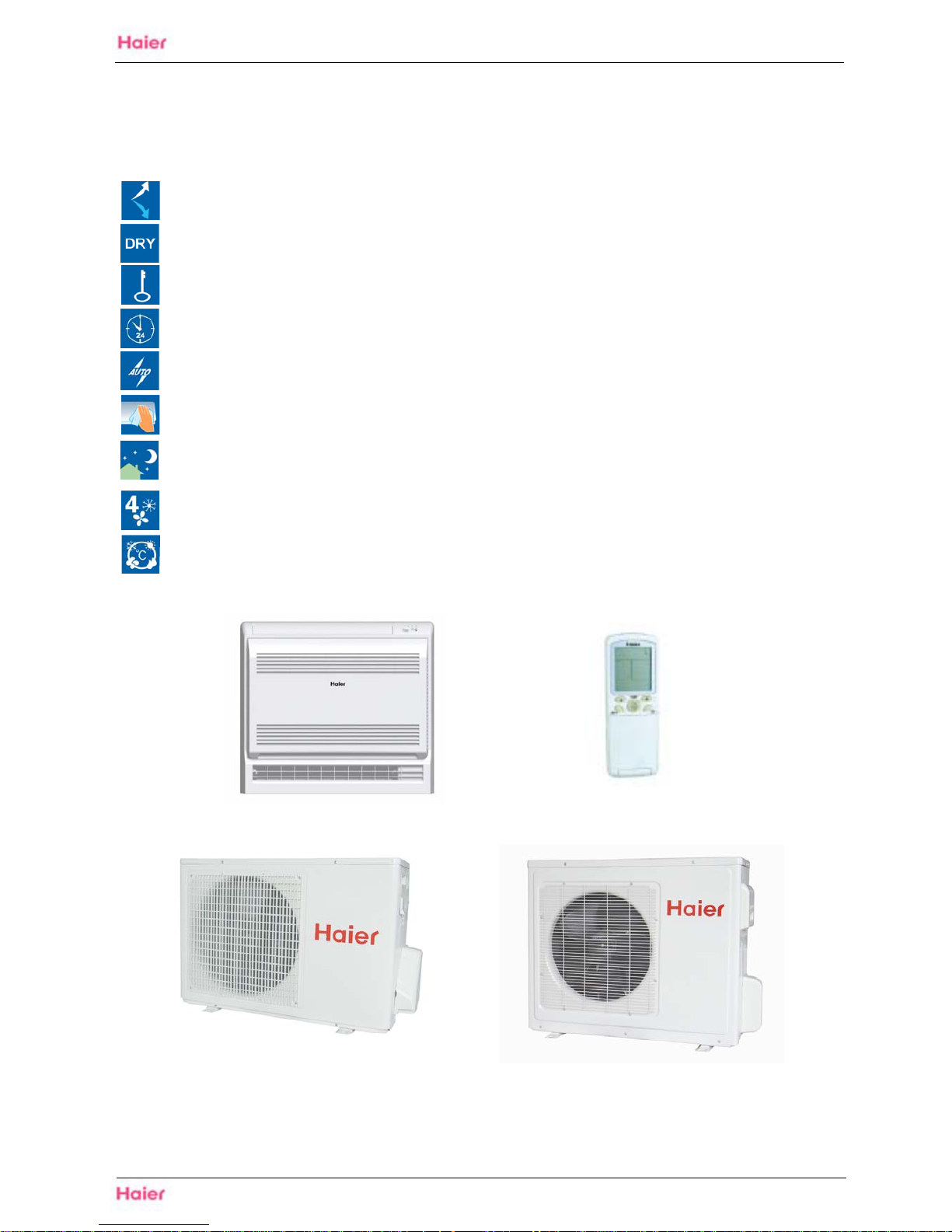
Carpet airflow: This setting blows air from upper outlet only or from both upper and lower outlet
Dry function: Make dehumidifying in the room when the unit is working in the "DRY" mode
Child lock: Avoid the child's wrong operation on the remote controller
24 Hour timer: Use the timer function to set on,or off,or from on to off,or from off to on
Auto restart: The function permits automatic return to previous peration conditions
Easy clean design: The panel is easy to wash and the airflow vents can be detached without
any special tools for quick cleaning of the inside of the air conditioner
Sleep mode: The setting temprature and the indoor noise can be adjusted to a more
comfortable level when you set the "sleep mode"during night sleep
4 Fan setting: Slect the fan speed LO,MED,HI,AUTO
Entire auto mode: You can set a tempreture value,with which the unit can be adjusted
theoperation mode automatically
1
Features
Domestic air conditioner
1. Features
HFU-09,12,18 HA03/R2(DB)
HFU-09,12 HA03/R2(DB)
HFU-18 HA03/R2(DB)

HFU-09,12,18HA03/R2(DB) Specifications
2
Domestic Air Conditioner
2. Specifications
NOMINALCAPACITY and NOMINAL INPUT
Model HFU-09HA03/R(DB) HFU-12HA03/R(DB) HFU-18HA03/R(DB)
Cooling(1) min.~norm.~max. w 750.~2600.~3200. 850.~3600.~4200. 1050.~5000.~5800. NORMINAL
CAPACITY(3-4)
Heating(2) min.~norm.~max. w 800.~3200.~4000. 1000.~4000.~4500. 1200.~6000.~7000.
Cooling min.~norm.~max. w 300.~760.~1150. 320.~1100.~1450. 420.~1550.~2100. NORMINAL
INPUT
Heating min.~norm.~max. w 350.~880.~1200. 380.~1100.~1600. 550.~1650.~2300.
EER Cooling 3.42 3.27 3.23
COP Heating 3.63 3.63 3.63
ANNUAL ENERGY
CONSUMPTION(9)
Cooling kwh 400 540 750
TECHNICAL SPECIFICATIONS
INDOOR UNITS HFU-09HA03/R(DB) HFU-12HA03/R(DB) HFU-18HA03/R(DB)
H mm 640 640 640
W mm 720 720 720
DIMENSIONS Unit
D mm 255 255 255
WEIGHT Unit KG 17 17.5 17.5
COLOR Unit WHITE WHITE WHITE
high dB(A) 42/41 44/43 48/47
medium dB(A) 39/38 41/40 45/43
Sound
pressure(cooling/heating)(5)
low dB(A) 37/35 38/36 42/40
SOUND
LEVEL
Sound
power(cooling/heating)(6)
high dB(A) 52/51 54/53 58/57
high m3 /min 7.5 8.5 11
medium m3 /min 6 7.5 9.5
Air flow
rate(cooling/h
eating)
low m3 /min 4.8 6 8.5
steps 4steps,silent and auto 4steps,silent and auto 4steps,silent and auto
high rpm 900 1000 1200
medium rpm 850 975 1125
Speed(cooling
/heating)
low rpm 800 850 1050
Type Cross flow fan Cross flow fan Cross flow fan
FAN
Motor output(upper/lower)
20/11 20/11 20/11
AIR FILTER
Removable/washable/
mildew proof
Removable/washable/
mildew proof
Removable/washable/
mildew proof
REMOTE CONTROLLER YR-H05 YR-H05 YR-H05
liquid mm 6.35 6.35 6.35
gas mm
9.52 9.52 12.7
PIPING
CONNECTIONS(external
diameter)
drain mm 16 16 16
INSULATION MATERIAL
Heat insulation type
both liquid and gas
pipes
both liquid and gas
pipes
both liquid and gas
pipes

HFU-09,12,18HA03/R2(DB) Specifications
3
TECHNICAL SPECIFICATIONS
OUTDOOR UNITS HFU-09HA03/R(DB) HFU-12HA03/R(DB) HFU-18HA03/R(DB)
H mm 543 543 680
W mm 783 783 813
NET DIMENSIONS(stop
valve, and bottom
supportis not included)
Unit
D mm 255 255 312
WEIGHT Unit KG 31 33 44
COLOR Unit Ivory white Ivory white Ivory white
Sound
pressure(cooling/heating)(5)
high dB(A) 55/55 55/55 57/58
SOUND
LEVEL
Sound
power(cooling/heating)(6)
high dB(A) 65/65 65/65 67/68
high m3 /min 30.2/26.5 30.2/26.5 31.3/27.7
Air flow
rate(cooling/heating)
low m3 /min 18.7/15.3 18.7/15.3 20.5/16.8
high rpm 800 800 840
Speed(cooling/heating)
low rpm 500 500 500
Type Propeller fan Propeller fan Propeller fan
FAN
Motor output 20 20 35
Refrigerant type R410A R410A R410A
Refrigerant charge kg 0.65 1.0 1.1
Maximum allowable distance
between indoor and outdoor
m 15 15 20
Maximum allowable level difference m 7 7 10
REFRIGERANT
CIRCUIT
Refrigerant control Capillary Capillary Capillary
Type
DC Inverter DC Inverter DC Rotary
Model
DA89X1C-20FZ DA108X1C-20FZ3 5CS130XCC03
Motor output W
690 855 1405
Oil type
ESTER OIL VG74 ESTER OIL VG74 ESTER OIL VG74
COMPRESSOR
Oil charge volume
ml 370 480 480
liquid mm 6.35 6.35 6.35
gas mm
9.52 9.52 12.7
PIPING
CONNECTIONS
drain mm 16 16 16
INSULATION MATERIAL Heat insulation type
both liquid and gas
pipes
both liquid and gas
pipes
both liquid and gas
pipes
Domestic Air Conditioner

HFU-09,12,18HA03/R2(DB) Specifications
4
ELECTRICAL SPECIFICATIONS
Model HFU-09HA03/R(DB) HFU-12HA03/R(DB) HFU-18HA03/R(DB)
Phase 1PH 1PH 1PH
Frequency Hz 50 50 50
NORMINAL
DISTRIBUTION
SYSTIEM
VOLTAGE
Voltage V 230V~ 230V~ 230V~
Cooling A 3.5 5.0 6.8
Norminal running
current
Heating A 4.0 5.0 7.3
Cooling A 5.8 7.5 10.2 Maximum running
current
Heating A 5.3 7.0 10.2
Cooling A 1.1 1.2 1.5
CURRENT
Starting current
Heating A 1.1 1.2 1.5
Domestic Air Conditioner
NOTES
1 Nominal cooling capacities are based on: indoor temperature 27°CDB/19°CWB * outdoor temperature 35°CDB * refrigerant piping length:
5m * level difference: 0m.
2 Nominal heating capacities are based on: indoor temperature 20°CDB * outdoor temperature 7°CDB/6°CWB * refrigerant piping length
5m (horizontal) * level difference 0m.
3 Capacities are net, including a deduction for cooling (an addition for heating) for indoor fan motor heat.
4 Units should be selected on nominal capacity. Maximum capacity is limited to peak periods.
5
6 The sound power level is an absolute value indicating the ’’power’’ which a sound source generates.
7 Energy label: scale from A (most efficient) to G (less efficient).
8 The energy label Directive 2002/31/EC will enter into force once the relevant measurement standard will be published in the European
official Standard.
9 Annual energy consumption: based on average use of 500 running hours per year at full load (= nominal conditions)
The sound pressure level is measured in an anechoic room at 1m distance from the unit. It is a relative value, depending on the distance
and acoustic environment. For measuring conditions: please refer to item 8 of this chapter.
HFU-09,12,18HA03/R2(DB) Specifications
5
Domestic Air Conditioner
3. Remote controller lists
4. Sensors lists
Mode
HFU-09HA03/R(DB) HFU-12HA03/R(DB) HFU-18HA03/R(DB)
YR-H05 Y Y Y
INDOOR UNIT
Description Value Qty
Room sensor It's used for detecting room temperature 1
Pipe sensor It's used for detecting temperature of evaporator 1
OUTDOOR UNIT
Ambient sensor It's used for detecting temperature outdoor side 1
Defrosting sensor It's used for controlling outdoor defrosting at heating mode 1
Descharging sensor It's used for protecting compressor in case of over-heat 1

HFU-09,12,18HA03/R2(DB) Dimensional Drawings
6
Domestic Air Conditioner
5. Dimensional Drawings
Indoor

Dimensional drawings
7
Domestic air conditioner
Outdoor unit
HFU-09,12HA03/R2(DB)
HFU-09,12,18HA03/R2(DB)
2-way valve
6.35mm(1/4")
6.35mm(1/4")
3-way valve
9.52mm(3/8")
HFU-18HA03/R2(DB)
2-way valve
6.35mm(1/4")
3-way valve
12.7mm(1/2")
80
60
146
680
813
352
583
312
319.5
837
6.35mm(1/4")
55
783
543
255
840
68
74
8
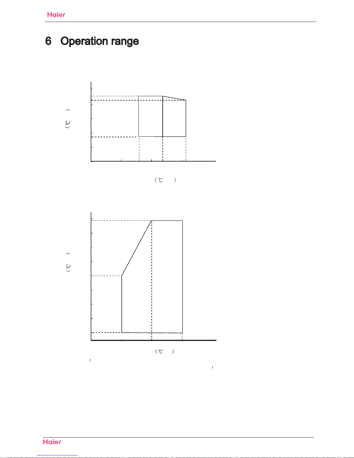
HFU-09,12,18 HA03/R2(DB) Operation range
Domestic air conditioner
Cooling
50
O
u
t
d
o
o
r
t
e
m
p
.
D
B
46
40 43
nwodllup03
20
18
10
0 16 23 32
10 20 30
indoor temp WB
25
gnitaeH42
20
o
u
t
d
o
o
r
t
e
m
p
WB
O
u
t
d
o
o
r
t
e
m
p
.
15
10
5
0
-5
-10
-15
10 20 30
indoor temp DB
Notes
The graphs are based on the following condition
Equivalent piping length 7.5m
Level difference 0m
hgihetar wolf riA
o
u
t
d
o
o
r
t
e
m
p
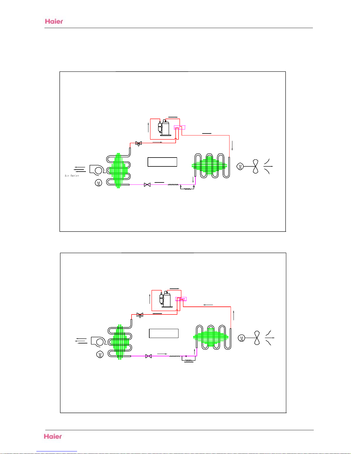
,QGRRU )DQ 0RWRU
UHJQDKF[(WDH+URRGQ,
UHJQDKF[(WDH+URRGWX2
&URVV )ORZ )DQ
3URSHOOHU )DQ
2XWGRRU )DQ 0RWRU
&RROLQJ 0RGH
&RPSUHVVRU
5HYHUVLQJ 9DOYH
/LTXLG 6WRS 9DOYH
*DV 6WRS 9DOYH
&KHFN 9DOYH
&KHFN 9DOYH
*DV 6WRS 9DOYH
/LTXLG 6WRS 9DOYH
5HYHUVLQJ 9DOYH
&RPSUHVVRU
+HDWLQJ 0RGH
2XWGRRU )DQ 0RWRU
3URSHOOHU )DQ
&URVV )ORZ )DQ
UHJQDKF[(WDH+URRGWX2
UHJQDKF[(WDH
+URRG
Q,
,QGRRU )DQ 0RWRU
&DSLOODU\ 7XEH
&DSLOODU\ 7XEH
+F8,12,18 HA 52 (D% 3LSLQJGLDJUDPV
9
'RPHVWLFDLUFRQGLWLRQHU
&RROLQJPRGH
$LURXWOHW
$LURXWOHW
$LURXWOHW
+HDWLQJPRGH
3LSLQJGLDJUDPV
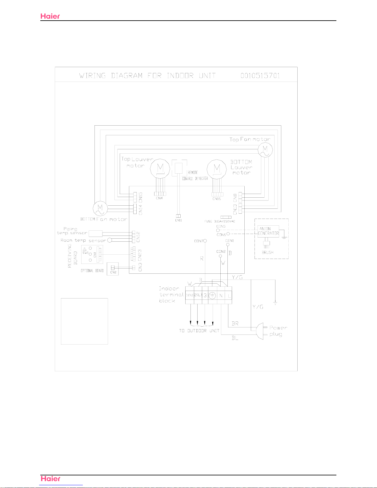
HFU-09,12,18HA03/R2(DB) Wiring Diagrams
10
Domestic Air Conditioner
8. Wiring Diagrams
Indoor(for 09/12 unit)
R:RED
B:BLACK
W:WHITE
Y/G:YELLOW/GREEN
Y/G
NOTES:
THE DOTTED PARTS ARE OPTIONAL
BL:BLUE
BR:BROWN

HFU-09,12,18HA03/R2(DB) Wiring Diagrams
11
Domestic Air Conditioner
Indoor(for 18 unit)
R:RED
B:BLACK
W:WHITE
Y/G:YELLOW/GREEN
Y/G
NOTES:
THE DOTTED PARTS ARE OPTIONAL

HFU-09,12,18HA03/R2(DB) Wiring Diagrams
12
Domestic Air Conditioner
Outdoor(for 09/12 unit)
0010510022
TO BILATERAL FRESH AIR MOTOR
TO FRESH AIR MOTOR
D
C
M
O
T
O
R
A
C
M
O
T
O
R
VALVE
EXPANSION
FOUR-WAY VALVE
TO INDOOR UNIT
BLOCK
TERMINAL
REACTOR
B:BLACK
BL:BLUE
R:RED
W:WHITE
NOTES:
DISCHARGE TEMP.SENSOR
AMBIENT TEMP.SENSOR
SUCTION TEMP.SENSOR
DEFROST TEMP.SENSOR
WIRING DIAGRAM OF OUTDOOR UNIT
NOTES
WARNING
DON'T TOUCH CAPACITOR, EVEN AFTER
PLUG-OFF ( DANGER OF ELECTRIC SHOCK)
The capacitor retains high
voltage even after the plug-off.
For your safety, be sure to wait
at least 5 minutes. after plug
off and use a tester to confirm
the voltage between connector
CN301 and CN302 is less than DC
10V before start servicing.
F
U
S
E
2
CN25
FUSE1
ELCTRIC
HEATING
CABLE
CN24
CN23
NOTES:THE DOTTED PARTS
ARE OPTIONAL.
T
2
5
A
/
2
5
0
V
A
C
CN13
CN10
CN11
(CN7)
(CN6)
AC-N
AC-L
W
CN12
CN14
CN8
CN7
CN16
LI
LO
W
(CN8)
(CN9)
CN11
CN10
POWER MODULE
CN3
CN4
CN5
Outdoor(for 18 unit)
T25A/250VAC
0010562188
OUTDOOR UNIT WIRING DIAGRAM
DON'T TOUCH CAPACITOR, EVEN AFTER
PLUG-OFF ( DANGER OF ELECTRIC SHOCK)
The capacitor retains high
voltage even after the plug-off.
For your safety, be sure to wait
at least 5 minutes. after plug
off and use a tester to confirm
the voltage between connector P
and N is less than DC 10V before
start servicing.
WARNING
CAUTION
/GREEN
Y/G:YELLOW
W: WHITE
OR:ORANGE
BL:BLUE
B: BLACK
R: RED
TERMINAL BLOCK
Double-way air exchange
MOTOR
POWER SUPPLY
TO INDOOR
REACTOR
COMPRESSOR
CAP BOARD
OUTDOOR PCB
(CN3)
(CN4)
AC-N
AC-L
NOTES:
THE PARTS OF DOTTED ARE OPTIONAL
W
P512
LI
LO
W
(CN1)
(CN2)
DEFROST TEMP.SENSOR
COMP.TEMP.SENSOR
AMBIENT TEMP.SENSOR
SUCTION.TEMP.SENSOR
EXPANSION VALVE
ELECTRIC
4-WAY VALVE
F
U
S
E
MODULE BOARD
CN10
CN11
F
L
I
T
E
R
R
Single-way air exchange
MOTOR
DC FAN MOTOR
AC FAN MOTOR
 Loading...