

Page 1

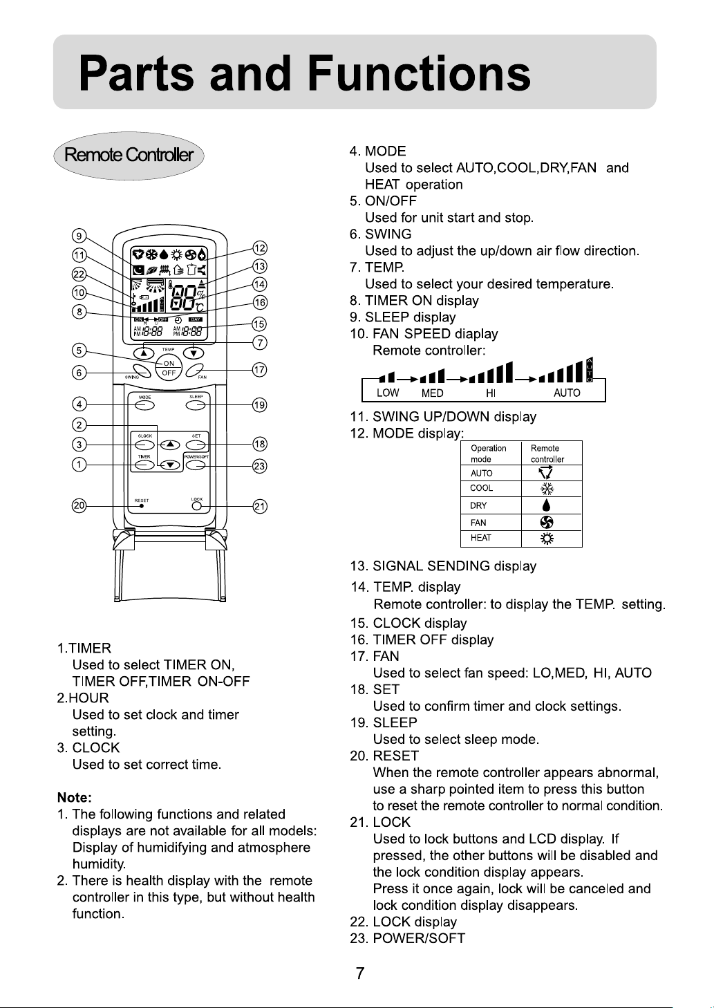
FLOOR UNIT
OPERATION MANUAL
AZ092AOBHA
AU092ACBHA
(HFU-09H03(B)/R1)
AZ122AOBHA
AU122ADBHA
(HFU-12H03(B)/R1)
AZ142AOBHA
AU142ADBHA
(HFU-14H03(B)/R1)
Please read this operation manual
before using the air conditioner.
E
Page 2

Page 3

Cautions
Do not obstruct or cover the ventilation
grille of the air conditioner. Do not put
fingers or any other things into the
inlet/outlet and swing louver.
Do not allow children to play with the air
conditioner. In no case should children be
allowed to sit on the outdoor unit.
Specifications
The refrigerating circuit is leak-proof.
The machine is adaptive in following
situation
1. Applicable ambient temperature range:
Indoor
Cooling
Outdoor
Indoor
Heating
Outdoor
Maximum: D.B/W.B 32OC / 23OC
Minimum: D.B/W.B 18OC / 14OC
Maximum: D.B/W.B 43OC / 26OC
Minimum: D.B 18OC
Maximum: D.B 27OC
Minimum: D.B 15OC
Maximum: D.B/W.B 24OC / 18OC
Minimum: D.B/W.B -15
O
C
7. The appliance is not intended for use by
young children or infirm persons without
supervision.
8. Young children should be supervised to
ensure that they do not play with the
applience.
9. A breaker should be used in the circuits,
which should be all-pole cutoff and the
distance between its two contacts
be not at least 3mm .
10.Please employ the proper power plug,
which fit into the power supply cord.
11.The power plug must have acquired the
local attestation.
should
2. If the power supply cord is damaged, it
must be replaced by the manufacturer
or its service agent or a similar qualified
person.
3. If the fuse of indoor unit on PC board is
broken,please change it with the type of
T. 3.15A/ 250V. If the fuse of outdoor unit
is broken, change it with the type of
T.25A/250V.
4. The wiring method should be in line with
the local wiring standard.
5. After installation, the power plug should
be easily reached.
6. The waste battery should be disposed
properly.
2
Page 4

Page 5

Page 6

Parts and Functions
Indoor unit
Outdoor unit
1.OUTLET
2.CONTROL PANEL
1
2
3
4
5
3.INLET
4.FILTER ( inside )
5.OUTLET
HFU-09H03(B)/R1
HFU-12H03(B)/R1
HFU-14H03(B)/R1
5
Page 7

Page 8
Page 9
Page 10

Page 11

Page 12

Page 13

Page 14

Page 15

Page 16

Page 17

Page 18

Page 19
Page 20

Page 21

Page 22

Page 23

Page 24
Installation Manual of Room Air Conditioner
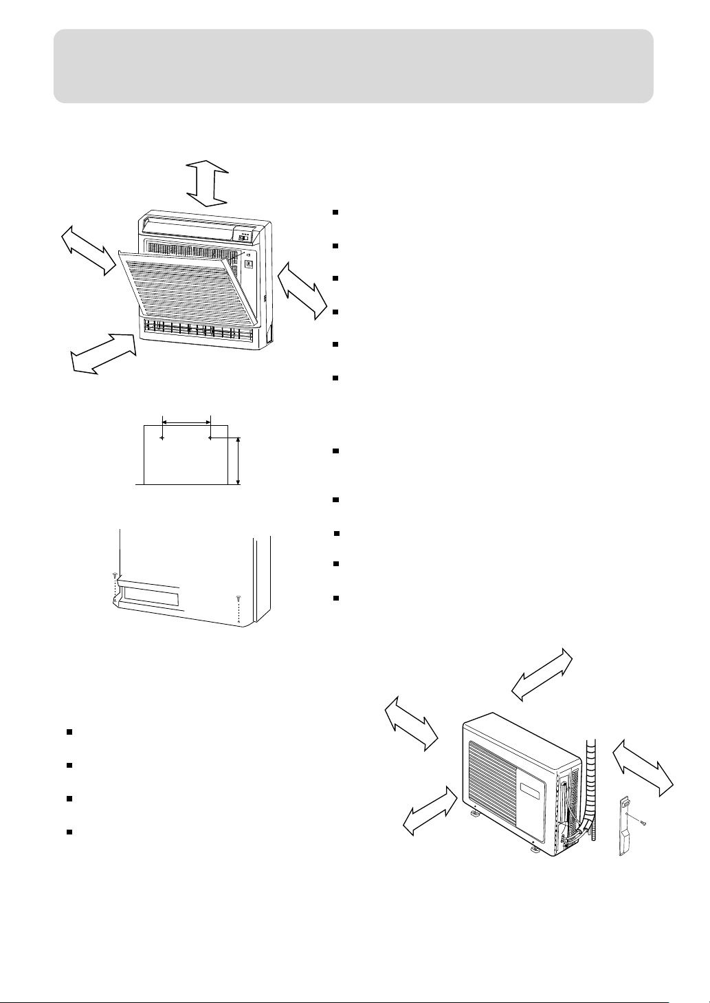
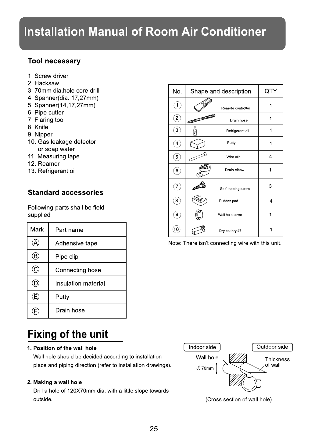
Installation of indoor unit
more than 10 cm
more than 100 cm
Figure .1
330
Figure .2
Figure .3
more than 10cm
selection of installation place
Place where it is easy to route drainage pipe
and outdoor piping.
Place ,away from heat source and with less
more than 10 cm
direct sunlight.
Place where cool and warm air could be
delivered evently to every corner of the room.
Place near power supply socket.Leave enough
space around the unit.
Place ,robust not causing vibration,where the
body can be supported sufficiently.
To
prevent interference, place it at least 1m
away from other electric machines, such as
TV set, radio.
Installation
According to the dimension of the Figure 2 shown
617
nail two cement steel nails on the wall.keep 2~3mm
out .then hang the back of the unit on them.
There must be no gap between the indoor unit and
wall.
Remove the front panel,then use two fastening
screws to fix the unit on the floor.As Figure 3 shown.
Once refrigerant piping and drain piping connections
are complete,fill the gap of the through hole with putty.
Attach the front panel and front grille in their orginal
positions once all connections are complete.
Installation of outdoor unit
selection of installation place
Place strong enough to support the unit and will
not cause vibration and noise.
Place where discharged wind and noise doesnt
cause a nuisance to the neighbors.
Place where is less affected by rain or direct sunlight
and is sufficiently ventilated,or to install a shield.
Place with enough space for smooth air flow.
24
more than 10 cm
more than 10 cm
more than 10 cm
more than 60 cm
Figure .4
Page 25

Page 26
Page 27

Installation Manual of Room Air Conditioner
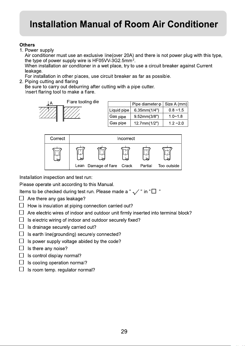
3. Piping connection
Connecting method
Apply refrigerant oil at half union and flare nut.
To bent a pipe, give the roundness as large as possible not to crash the pipe.
When connecting pipe, hold the pipe center to center then screw nut on by hand, refer to Fig.
Be careful not to let foreign matters, such as sands enter the pipe.
Forced fastening without careful
centering may damage the
threads and cause a leakage of
gas.
Pipe Diameter ( )
Liquid Side
Gas Side 12.7mm(1/ 2") 50N.m
Piping connection of the indoor unit
1. Arrangement of piping
Remove the cover before working.
Cut away, with a hammer or a saw, the lid for piping according to piping direction.
According to the piping method, connect the piping on indoor unit with union of connection pipe.
Arrange the piping as per the wall hole and bind drain hose connecting electric cable and piping
together with polyethylene tape.
Insert the bound piping connecting electric cable and drain hoes through wall hole to connect
with outdoor unit.
and drainage pipe
insulation material
Copper tube
Connecting electric cable for
indoor and outdoor unit
6.35mm(1/4")
Drain hose
Fastening Torque
18N.m
2. Arrangement drain hose
Drain hose shall be placed in under place.
There should be a slope when arrange drain hose. Avoid up and down waves in drain hose.
If humidity is high, drain pipe(especially in room and indoor unit) must be covered with
installation material.
26
Page 28

Page 29

Installation Manual of Room Air Conditioner
Note: When additional refrigerant is necessary, first purge air out of connecting pipe by external gas,
then drive out the excessive rerigerant by purging method.
Brand new unit is charged 80g more refrigerant than spec. This is only for first instaltion to purge air
in the indoor unit and connecting pipe.
When piping is longer than 5m, charge additional refrigerant specified in this list.
Pipe length 5m 10m 15m
Refrigerant charge(g) 90 180
Electric wiring
Note:
Electric wiring must be done by qualified person.
Use copper wire only.
The parameter of the connecting cable is
HFU-09H03(B)/R1:3G1.5mm2+1X0.75mm
HFU-12H03(B)/R1:3G2.5mm2+1X0.75mm
HFU-14H03(B)/R1:3G2.5mm2+1X0.75mm
Wiring of indoor unit
Insert the cable from outside the wall hole where piping already exist.
Pull it out from front.
Losen terminal screw and insert cable end fully into terminal block, then tighten it
Pull the cable gently to make sure it is tight.
Replace cover after wiring.
H05RN-F or H07RN-F
2
2
2
Indoor unit
Terminal block
Wire clip
Wire loop
Guounding Screw
White
Black
Yellow/Green
Red
Outdoor unit
Wiring of outdoor unit
Insert the cable from inside the wall hole where piping already exist.
Pull it out from front.
Loose terminal screw and insert cable end fully into terminal block, then tighten it
Pull the cable gently to make sure it is tight.
Replace cover after wiring.
Note:
When connecting indoor and outdoor wire, check the number on indoor and outdoor terminal
blocks. Terminals of same number and same color shall be connected by the same wire.
Incorrect wiring may damage air conditioner’s control or cause operation failure.
power
28
Page 30
 Loading...