

Page 1

Domestic
Air conditioner
DC Inverter
CAUTION
1. READ THIS MANUAL CAREFULLY TO
DIAGNOSE TROUBLE CORRECTLY
BEFORE OFFERING SERVICE.
2. THIS MANUAL IS USED BY QUALIFIED
APPLIANCE TECHNICIANS ONLY.
3. HAIER DOES NOT ASSUME ANY
RESPONSIBILITY FOR PROPERTY
DAMAGE OR PERSONAL INJURY FOR
IMPROPER
Console Type
HFU-09HA03/R(DB)
HFU-12HA03/R(DB)
HFU-18HA03/R(DB)
SERVICE PROCEDURES DONE BY ONE
UNQUALIFIED PERSON.
Page 2

HFU-09,12,18HA03/R2(DB)
stnetnoCfoelbaT
Table of Contents
1. Features.…………………………...…………………………..…….…….…............ 1
2. Specifications……….……………………………….……………. .….….……….. 2
3. Remote controller lists…….…………..………….….….……….………………... 5
4. Sensors lists…...….….…………………………………………………………........ 5
5. Dimensional drawings…………………………………………………………….....6
6. Operation range……………………………………...…………………………….....8
7. Piping diagrams……………………………………………………………. .…….... 9
8. Wiring diagrams………………………………………………….…………….........10
9. Performance curves diagrams ...............………………………………. ……...13
9.1 Cooling capacity-temperature curves..................................................................................13
9.2 Heating capacity-temperature curves………………………………………...........................
9.3 Cooling power consumption value curves..........................................................................19
9.4 Heating
9.5 Cooling discharge pressure cu rves...................................................................................
9.6 Cooling suction pressure cu rves........................................................................................
9.7 Heating discharge
9.8 Heating suction pressure curves........................................................................................
power consumption value curves..........................................................................
pressure curves.....................................................................................31
10. Sound level……………………………………………………… ………………...
16
22
25
28
34
37
11. Accessories……………………………………………………………………….. 38
12. Control systems…………………………………………………………………..
13. Center of gravity…………………………………………………………………..
14. Installations……………………………………………………………………..…
The end
…….........................................................................................................
Domestic air conditioner
39
40
41
42
Page 3

HFU-09,12,18 HA03/R2(DB)
Features
1. Features
Carpet airflow: This setting blows air from upper outlet only or from both upper and lower outlet
Dry function: Make dehumidifying in the room when the unit is working in the "DRY" mode
Child lock: Avoid the child's wrong operation on the remote controller
24 Hour timer: Use the timer function to set on,or off,or from on to off,or from off to on
Auto restart: The function permits automatic return to previous peration conditions
Easy clean design: The panel is easy to wash and the airflow vents can be detached without
any special tools for quick cleaning of the inside of the air conditioner
Sleep mode: The setting temprature and the indoor noise can be adjusted to a more
comfortable level when you set the "sleep mode"during night sleep
4 Fan setting: Slect the fan speed LO,MED,HI,AUTO
Entire auto mode: You can set a tempreture value,with which the unit can be adjusted
theoperation mode automatically
HFU-09,12 HA03/R2(DB)
HFU-18 HA03/R2(DB)
1
Domestic air conditioner
Page 4

HFU-09,12,18HA03/R2(DB) Specifications
2. Specifications
NOMINALCAPACITY and NOMINAL INPUT
Model HFU-09HA03/R(DB) HFU-12HA03/R(DB) HFU-18HA03/R(DB)
Cooling(1) min.~norm.~max. w 750.~2600.~3200. 850.~3600.~4200. 1050.~5000.~5800. NORMINAL
CAPACITY(3-4)
INPUT
EER Cooling 3.42 3.27 3.23
COP Heating 3.63 3.63 3.63
ANNUAL ENERGY
CONSUMPTION(9)
TECHNICAL SPECIFICATIONS
INDOOR UNITS HFU-09HA03/R(DB) HFU-12HA03/R(DB) HFU-18HA03/R(DB)
DIMENSIONS Unit
WEIGHT Unit KG 17 17.5 17.5
COLOR Unit WHITE WHITE WHITE
SOUND
LEVEL
FAN
PIPING
CONNECTIONS(external
diameter)
INSULATION MATERIAL
Heating(2) min.~norm.~max. w 800.~3200.~4000. 1000.~4000.~4500. 1200.~6000.~7000.
Cooling min.~norm.~max. w 300.~760.~1150. 320.~1100.~1450. 420.~1550.~2100. NORMINAL
Heating min.~norm.~max. w 350.~880.~1200. 380.~1100.~1600. 550.~1650.~2300.
Cooling kwh 400 540 750
H mm 640 640 640
W mm 720 720 720
D mm 255 255 255
Sound
pressure(cooling/heating)(5)
Sound
power(cooling/heating)(6)
Air flow
rate(cooling/h
eating)
Speed(cooling
/heating)
Type Cross flow fan Cross flow fan Cross flow fan
Motor output(upper/lower)
AIR FILTER
REMOTE CONTROLLER YR-H05 YR-H05 YR-H05
medium m3 /min 6 7.5 9.5
high rpm 900 1000 1200
medium rpm 850 975 1125
low rpm 800 850 1050
Heat insulation type
high dB(A) 42/41 44/43 48/47
medium dB(A) 39/38 41/40 45/43
low dB(A) 37/35 38/36 42/40
high dB(A) 52/51 54/53 58/57
high m3 /min 7.5 8.5 11
low m3 /min 4.8 6 8.5
steps 4steps,silent and auto 4steps,silent and auto 4steps,silent and auto
20/11 20/11 20/11
Removable/washable/
mildew proof
liquid mm 6.35 6.35 6.35
gas mm
drain mm 16 16 16
9.52 9.52 12.7
both liquid and gas
pipes
Removable/washable/
mildew proof
both liquid and gas
pipes
Removable/washable/
mildew proof
both liquid and gas
pipes
2
Domestic Air Conditioner
Page 5

HFU-09,12,18HA03/R2(DB) Specifications
TECHNICAL SPECIFICATIONS
OUTDOOR UNITS HFU-09HA03/R(DB) HFU-12HA03/R(DB) HFU-18HA03/R(DB)
NET DIMENSIONS(stop
valve, and bottom
supportis not included)
WEIGHT Unit KG 31 33 44
COLOR Unit Ivory white Ivory white Ivory white
SOUND
LEVEL
FAN
REFRIGERANT
CIRCUIT
COMPRESSOR
CONNECTIONS
pressure(cooling/heating)(5)
power(cooling/heating)(6)
Air flow
rate(cooling/heating)
Speed(cooling/heating)
Type Propeller fan Propeller fan Propeller fan
Maximum allowable distance
between indoor and outdoor
Maximum allowable level difference m 7 7 10
PIPING
INSULATION MATERIAL Heat insulation type
Unit
Sound
Sound
Motor output 20 20 35
Refrigerant type R410A R410A R410A
Refrigerant charge kg 0.65 1.0 1.1
Refrigerant control Capillary Capillary Capillary
Motor output W
Oil charge volume
liquid mm 6.35 6.35 6.35
gas mm
drain mm 16 16 16
H mm 543 543 680
W mm 783 783 813
D mm 255 255 312
high dB(A) 55/55 55/55 57/58
high dB(A) 65/65 65/65 67/68
high m3 /min 30.2/26.5 30.2/26.5 31.3/27.7
low m3 /min 18.7/15.3 18.7/15.3 20.5/16.8
high rpm 800 800 840
low rpm 500 500 500
m 15 15 20
Type
Model
Oil type
ml 370 480 480
DC Inverter DC Inverter DC Rotary
DA89X1C-20FZ DA108X1C-20FZ3 5CS130XCC03
690 855 1405
ESTER OIL VG74 ESTER OIL VG74 ESTER OIL VG74
9.52 9.52 12.7
both liquid and gas
pipes
both liquid and gas
pipes
both liquid and gas
pipes
3
Domestic Air Conditioner
Page 6

ELECTRICAL SPECIFICATIONS
Model HFU-09HA03/R(DB) HFU-12HA03/R(DB) HFU-18HA03/R(DB)
NORMINAL
DISTRIBUTION
SYSTIEM
VOLTAGE
Frequency Hz 50 50 50
Voltage V 230V~ 230V~ 230V~
HFU-09,12,18HA03/R2(DB) Specifications
Phase 1PH 1PH 1PH
Norminal running
current
CURRENT
current
Starting current
NOTES
1 Nominal cooling capacities are based on: indoor temperature 27°CDB/19°CWB * outdoor temperature 35°CDB * refrigerant piping length:
5m * level difference: 0m.
2 Nominal heating capacities are based on: indoor temperature 20°CDB * outdoor temperature 7°CDB/6°CWB * refrigerant piping length
5m (horizontal) * level difference 0m.
3 Capacities are net, including a deduction for cooling (an addition for heating) for indoor fan motor heat.
4 Units should be selected on nominal capacity. Maximum capacity is limited to peak periods.
The sound pressure level is measured in an anechoic room at 1m distance from the unit. It is a relative value, depending on the distance
5
and acoustic environment. For measuring conditions: please refer to item 8 of this chapter.
6 The sound power level is an absolute value indicating the ’’power’’ which a sound source generates.
7 Energy label: scale from A (most efficient) to G (less efficient).
8 The energy label Directive 2002/31/EC will enter into force once the relevant measurement standard will be published in the European
official Standard.
9 Annual energy consumption: based on average use of 500 running hours per year at full load (= nominal conditions)
Cooling A 3.5 5.0 6.8
Heating A 4.0 5.0 7.3
Cooling A 5.8 7.5 10.2 Maximum running
Heating A 5.3 7.0 10.2
Cooling A 1.1 1.2 1.5
Heating A 1.1 1.2 1.5
4
Domestic Air Conditioner
Page 7

HFU-09,12,18HA03/R2(DB) Specifications
3. Remote controller lists
Mode
HFU-09HA03/R(DB) HFU-12HA03/R(DB) HFU-18HA03/R(DB)
YR-H05 Y Y Y
4. Sensors lists
INDOOR UNIT
Description Value Qty
Room sensor It's used for detecting room temperature 1
Pipe sensor It's used for detecting temperature of evaporator 1
OUTDOOR UNIT
Ambient sensor It's used for detecting temperature outdoor side 1
Defrosting sensor It's used for controlling outdoor defrosting at heating mode 1
Descharging sensor It's used for protecting compressor in case of over-heat 1
5
Domestic Air Conditioner
Page 8

HFU-09,12,18HA03/R2(DB) Dimensional Drawings
5. Dimensional Drawings
Indoor
6
Domestic Air Conditioner
Page 9

Outdoor unit
HFU-09,12HA03/R2(DB)
HFU-09,12,18HA03/R2(DB)
Dimensional drawings
74
55
2-way valve
6.35mm(1/4")
3-way valve
6.35mm(1/4")
9.52mm(3/8")
68
543
840
783
255
HFU-18HA03/R2(DB)
2-way valve
6.35mm(1/4")
3-way valve
6.35mm(1/4")
12.7mm(1/2")
60
80
146
680
837
813
583
319.5
312
352
7
Domestic air conditioner
Page 10

50
46
40 43
HFU-09,12,18 HA03/R2(DB) Operation range
Cooling
B
D
.
.
p
p
m
m
e
e
t
t
r
r
o
o
o
o
d
d
t
t
u
u
O
O
WB
nwodllup03
20
18
10
0 16 23 32
10 20 30
indoor temp WB
25
gnitaeH42
20
15
10
p
p
m
m
e
e
t
t
r
r
o
o
o
o
d
d
t
t
u
u
o
o
Notes
5
0
-5
-10
-15
10 20 30
indoor temp DB
The graphs are based on the following condition
Equivalent piping length 7.5m
Level difference 0m
hgihetar wolf riA
8
Domestic air conditioner
Page 11

+F8,12,18 HA 52 (D% 3LSLQJGLDJUDPV
3LSLQJGLDJUDPV
&RROLQJPRGH
5HYHUVLQJ 9DOYH
&URVV )ORZ )DQ
,QGRRU )DQ 0RWRU
+HDWLQJPRGH
*DV 6WRS 9DOYH
&KHFN 9DOYH
UHJQDKF[(WDH+URRGQ,
/LTXLG 6WRS 9DOYH
&RPSUHVVRU
&RROLQJ 0RGH
&DSLOODU\ 7XEH
3URSHOOHU )DQ
UHJQDKF[(WDH+URRGWX2
2XWGRRU )DQ 0RWRU
$LURXWOHW
$LURXWOHW
&URVV )ORZ )DQ
,QGRRU )DQ 0RWRU
5HYHUVLQJ 9DOYH
*DV 6WRS 9DOYH
&KHFN 9DOYH
Q,
+URRG
UHJQDKF[(WDH
/LTXLG 6WRS 9DOYH
&RPSUHVVRU
+HDWLQJ 0RGH
&DSLOODU\ 7XEH
3URSHOOHU )DQ
$LURXWOHW
2XWGRRU )DQ 0RWRU
UHJQDKF[(WDH+URRGWX2
9
'RPHVWLFDLUFRQGLWLRQHU
Page 12

8. Wiring Diagrams
Indoor(for 09/12 unit)
HFU-09,12,18HA03/R2(DB) Wiring Diagrams
R:RED
B:BLACK
W:WHITE
BL:BLUE
BR:BROWN
Y/G:YELLOW/GREEN
NOTES:
THE DOTTED PARTS ARE OPTIONAL
Y/G
10
Domestic Air Conditioner
Page 13

Indoor(for 18 unit)
HFU-09,12,18HA03/R2(DB) Wiring Diagrams
R:RED
B:BLACK
W:WHITE
Y/G:YELLOW/GREEN
NOTES:
THE DOTTED PARTS ARE OPTIONAL
Y/G
11
Domestic Air Conditioner
Page 14

HFU-09,12,18HA03/R2(DB) Wiring Diagrams
Outdoor(for 09/12 unit)
WARNING
NOTES
DON'T TOUCH CAPACITOR, EVEN AFTER
PLUG-OFF ( DANGER OF ELECTRIC SHOCK)
The capacitor retains high
voltage even after the plug-off.
For your safety, be sure to wait
at least 5 minutes. after plug
off and use a tester to confirm
the voltage between connector
CN301 and CN302 is less than DC
10V before start servicing.
DEFROST TEMP.SENSOR
AMBIENT TEMP.SENSOR
SUCTION TEMP.SENSOR
DISCHARGE TEMP.SENSOR
NOTES:THE DOTTED PARTS
ARE OPTIONAL.
WIRING DIAGRAM OF OUTDOOR UNIT
CN11
CN10
2
/
A
5
2
T
CN23
CN24
A
C
M
O
O
T
R
FOUR-WAY VALVE
CN14
CN10
CN11
CN12
CN13
CN8
CN16
EXPANSION
VALVE
CN7
CN4
CN5
CN3
D
C
M
T
O
O
R
POWER MODULE
C
A
V
0
5
FUSE1
2
E
S
U
CN25
F
LI
(CN7)
(CN8)
AC-L
(CN9)
AC-N
LO
(CN6)
CABLE
ELCTRIC
HEATING
NOTES:
B:BLACK
R:RED
BL:BLUE
0010510022
W
W
TERMINAL
BLOCK
REACTOR
TO INDOOR UNIT
TO FRESH AIR MOTOR
TO BILATERAL FRESH AIR MOTOR
W:WHITE
Outdoor(for 18 unit)
OUTDOOR UNIT WIRING DIAGRAM
WARNING
CAUTION
DON'T TOUCH CAPACITOR, EVEN AFTER
PLUG-OFF ( DANGER OF ELECTRIC SHOCK)
The capacitor retains high
voltage even after the plug-off.
For your safety, be sure to wait
at least 5 minutes. after plug
off and use a tester to confirm
the voltage between connector P
and N is less than DC 10V before
start servicing.
DEFROST TEMP.SENSOR
AMBIENT TEMP.SENSOR
SUCTION.TEMP.SENSOR
COMP.TEMP.SENSOR
NOTES:
THE PARTS OF DOTTED ARE OPTIONAL
COMPRESSOR
EXPANSION VALVE
OUTDOOR PCB
ELECTRIC
DC FAN MOTOR
CN11
CN10
CAP BOARD
AC FAN MOTOR
MODULE BOARD
4-WAY VALVE
0010562188
LI
(CN3)
W
(CN1)
AC-L
(CN2)
AC-N
W
LO
(CN4)
R
E
T
I
L
F
P512
Double-way air exchange
MOTOR
Single-way air exchange
MOTOR
E
S
U
F
T25A/250VAC
REACTOR
TERMINAL BLOCK
R
POWER SUPPLY
TO INDOOR
B: BLACK
R: RED
OR:ORANGE
BL:BLUE
W: WHITE
Y/G:YELLOW
/GREEN
12
Domestic Air Conditioner
Page 15

HFU-09,12,18 HA03/R2(DB) Performance Curves
9 Performance Curves Diagram
9.1 Cooling Capacity-temperature Curves
HFU-09HA03/R2(DB) performance curves
cooling capacity and indoor/outdoor temp.talbe
indoor temp.
DB/WB 18℃ 20℃ 25℃ 32℃ 35℃ 40℃ 43℃ 46℃
18/12℃ 2127 1976 1859 1779 1617 1400 1317 1198
18/14℃ 2254 2095 1910 1828 1700 1475 1367 1248
20/15℃ 2353 2169 2003 1917 1821 1631 1469 1348
22/16℃ 2561 2333 2174 2080 1992 1829 1617 1483
25/18℃ 2688 2547 2412 2308 2247 2075 1842 1662
27/19℃ 2892 2734 2642 2529 2437 2250 2075 1877
30/22℃ 2965 2844 2728 2611 2525 2367 2200 2021
32/23℃ 3080 2956 2847 2724 2650 2550 2375 2216
32/24℃ 3122 2998 2924 2798 2742 2625 2433 2293
Cooling capacity and indoor/outdoor temp.curves
3000
outdoor temp.(humidity 46%)
2500
2000
power consumption(w)
1500
1000
18℃
20℃
25℃
32℃
35℃
40℃
43℃
46℃
4℃
2
2/
3
3
0/
2℃
2
6℃
1
2/
2
indoor tempe.(DB/WB)
1
8/
4℃
1
2℃
1
8/
1
5℃
1
0/
2
8℃
1
5/
2
9℃
1
7/
2
13
Domestic air conditioner
3℃
2
2/
3
Page 16

HFU-09,12,18 HA03/R2(DB) Performance Curves
HFU-12HA03/R2(DB) performance curves
cooling capacity and indoor/outdoor temp.talbe
indoor temp.
outdoor temp.(humidity 46%)
DB/WB 18℃ 20℃ 25℃ 32℃ 35℃ 40℃ 43℃ 46℃
18/12℃ 3130 2910 2720 2524 2377 2200 1940 1577
18/14℃ 3310 3080 2840 2684 2530 2283 2020 1706
20/15℃ 3503 3300 2990 2840 2634 2366 2160 1783
22/16℃ 3750 3440 3210 3020 2770 2541 2310 1990
25/18℃ 3871 3663 3466 3276 3140 2797 2593 2198
27/19℃ 4091 3970 3797 3588 3420 3151 2889 2469
30/22℃ 4250 4070 3920 3740 3550 3330 3110 2804
32/23℃ 4390 4251 4091 3940 3830 3606 3360 3030
32/24℃ 4459 4312 4201 3970 3870 3695 3440 3090
Cooling capacity and indoor/outdoor temp.curves
4500
4000
3500
3000
2500
power consumption(w)
2000
1500
1
8/
12
℃
18℃
20℃
25℃
32℃
35℃
40℃
43℃
46℃
℃
14
8/
1
℃
15
0/
2
℃
16
2/
2
℃
18
5/
2
2
7/
19
℃
3
0/
22
℃
℃
23
2/
3
℃
24
2/
3
indoor tempe.(DB/WB)
14
Domestic Air Conditioner
Page 17

HFU-09,12,18 HA03/R2(DB) Performance Curves
HFU-18HA03/R2(DB) performance curves
cooling capacity and indoor/outdoor temp.talbe
indoor temp.
outdoor temp.(humidity 46%)
DB/WB 18℃ 20℃ 25℃ 32℃ 35℃ 40℃ 43℃ 46℃
18/12℃ 4399 4036 3771 3465 3061 2720 2386 2062
18/14℃ 4571 4144 3905 3571 3110 2780 2524 2231
20/15℃ 4748 4274 4091 3734 3404 3020 2541 2332
22/16℃ 5193 4785 4360 4052 3795 3338 2868 2602
25/18℃ 5451 5038 4825 4558 4315 3850 3262 2873
27/19℃ 5762 5408 5202 5039 4840 4320 3796 3228
30/22℃ 5921 5626 5430 5250 5050 4570 4086 3666
32/23℃ 6214 5847 5605 5410 5250 4770 4482 4039
32/24℃ 6280 5929 5756 5530 5361 4930 4636 4173
Cooling capacity and indoor/outdoor temp.curves
6500
6000
5500
5000
4500
4000
3500
power consumption(w)
3000
2500
2000
1
8/
12
℃
18℃
20℃
25℃
32℃
35℃
40℃
43℃
46℃
℃
14
8/
1
℃
15
0/
2
℃
16
2/
2
℃
18
5/
2
2
7/
19
℃
3
0/
22
℃
℃
23
2/
3
℃
24
2/
3
indoor tempe.(DB/WB)
15
Domestic Air Conditioner
Page 18

HFU-09,12,18 HA03/R2(DB) Performance Curves
)
9.2 Heatling Capacity-temperature Curves
HFU-09HA03/R2(DB) performance curves
heating capacity and indoor/outdoor temp.curves
outdoor temp.
DB/WB 15℃ 20℃ 25℃
-10℃ 2488 2116 1745
-5℃ 3010 2293 1816
5℃ 3228 2578 2107
7/6℃ 3626 3027 2481
15℃ 4300 3636 3112
20℃ 3947 3335 2937
25℃ 3782 3316 3053
indoor temp.(humidity 46%)
4500
4000
3500
3000
2500
conoling capacity( w
2000
1500
15℃
Heating capacity and indoor/outdoor temp.curves
20℃
25℃
1234567
indoor tempe.(DB/WB)
16
Domestic Air Conditioner
Page 19

HFU-09,12,18 HA03/R2(DB) Performance Curves
HFU-12HA03/R2(DB) performance curves
heating capacity and indoor/outdoor temp.curves
outdoor temp.
DB/WB 15℃ 20℃ 25℃
-10℃ 2874 2423 1885
-5℃ 3010 2550 2120
5℃ 3228 2850 2330
7/6℃ 4160 3667 2930
15℃ 4660 4130 3410
20℃ 3900 3650 3150
25℃ 3782 3500 3053
indoor temp.(humidity 46%)
5000
4500
4000
3500
3000
conoling capacity( w)
2500
2000
1500
Heating capacity and indoor/outdoor temp.curves
15℃
20℃
25℃
1234567
indoor tempe.(DB/WB)
17
Domestic Air Conditioner
Page 20

HFU-09,12,18 HA03/R2(DB) Performance Curves
HFU-18HA03/R2(DB) performance curves
heating capacity and indoor/outdoor temp.curves
outdoor temp.
DB/WB 15℃ 20℃ 25℃
-10℃ 4426 3780 2884
-5℃ 4635 3978 2953
5℃ 4971 4446 3565
7/6℃ 6406 5721 4483
15℃ 7176 6443 5217
20℃ 6006 5694 4820
25℃ 5824 5460 4671
indoor temp.(humidity 46%)
conoling capacity(w)
Heating capacity and indoor/outdoor temp.curves
7500
7000
6500
6000
5500
5000
4500
4000
3500
3000
2500
15℃
20℃
25℃
1234567
indoor tempe.(DB/WB)
18
Domestic Air Conditioner
Page 21

HFU-09,12,18 HA03/R2(DB) Performance Curves
9.3 Cooling Power Consumption Value-temperature Curves
HFU-09HA03/R2(DB) performance curves
cooling power consumption value-temp.talbe
indoor temp.
outdoor temp.(humidity 46%)
DB/WB 18℃ 20℃ 25℃ 32℃ 35℃ 40℃ 43℃ 46℃
18/12℃ 387 503 549 616 687 774 823 897
18/14℃ 401 521 581 652 704 802 869 931
20/15℃ 413 537 596 669 722 826 901 969
22/16℃ 427 555 615 691 735 835 922 993
25/18℃ 442 575 629 707 758 868 967 1047
27/19℃ 452 587 653 733 796 919 1012 1103
30/22℃ 488 634 695 797 881 1003 1088 1196
32/23℃ 542 704 777 865 981 1100 1170 1276
32/24℃ 571 743 804 902 1032 1139 1210 1289
Cooling power consumption value-temp.curves
1300
18℃
1200
1100
1000
900
800
20℃
25℃
32℃
35℃
40℃
43℃
46℃
700
600
power consumption(w)
500
400
300
18
20
/
℃
15
℃
12
/
℃
14
/
18
22
℃
16
/
25
/
℃
18
27
℃
19
/
30
/
℃
22
32
/
℃
23
32
/
℃
24
indoor tempe.(DB/WB)
19
Domestic air conditioner
Page 22

HFU-09,12,18 HA03/R2(DB) Performance Curves
HFU-12HA03/R2(DB) performance curves
cooling power consumption value-temp.talbe
indoor temp.
outdoor temp.(humidity 46%)
DB/WB 18℃ 20℃ 25℃ 32℃ 35℃ 40℃ 43℃ 46℃
18/12℃ 497 585 687 760 831 895 987 1108
18/14℃ 512 607 713 787 857 957 1024 1149
20/15℃ 532 632 742 853 930 972 1066 1197
22/16℃ 566 648 760 874 969 1023 1092 1226
25/18℃ 596 683 802 921 996 1068 1152 1293
27/19℃ 648 733 845 971 1083 1125 1213 1362
30/22℃ 697 818 942 1052 1166 1236 1316 1477
32/23℃ 755 905 1027 1159 1263 1336 1404 1576
32/24℃ 779 938 1077 1178 1303 1365 1418 1592
Cooling power consumption value-temp.curves
1600
18℃
1400
1200
1000
20℃
25℃
32℃
35℃
40℃
43℃
46℃
800
power consumption(w)
600
400
18
/
12
℃
18
/
14
℃
20
/
℃
16
℃
15
/
22
25
/
℃
18
27
/
℃
19
30
℃
22
/
32
/
℃
23
32
/
℃
24
indoor tempe.(DB/WB)
20
Domestic Air Conditioner
Page 23

HFU-09,12,18 HA03/R2(DB) Performance Curves
HFU-18HA03/R2(DB) performance curves
cooling power consumption value-temp.talbe
indoor temp.
outdoor temp.(humidity 46%)
DB/WB 18℃ 20℃ 25℃ 32℃ 35℃ 40℃ 43℃ 46℃
18/12℃ 619 831 961 1038 1105 1282 1422 1591
18/14℃ 632 863 997 1077 1193 1371 1475 1651
20/15℃ 677 898 1038 1171 1279 1392 1568 1718
22/16℃ 710 920 1064 1201 1365 1465 1626 1761
25/18℃ 800 970 1122 1269 1444 1529 1716 1857
27/19℃ 871 1042 1182 1394 1570 1671 1832 2000
30/22℃ 986 1163 1318 1535 1691 1819 1974 2181
32/23℃ 1068 1286 1437 1660 1865 1981 2122 2310
32/24℃ 1101 1333 1507 1687 1929 2032 2185 2348
Cooling power consumption value-temp.curves
2400
2200
2000
1800
1600
1400
18℃
20℃
25℃
32℃
35℃
40℃
43℃
46℃
power consumption(w)
1200
1000
800
600
400
18
22
/
℃
16
℃
12
/
℃
14
/
18
20
/
℃
15
25
/
℃
18
27
/
℃
19
30
/
℃
22
32
/
℃
23
32
℃
24
/
indoor tempe.(DB/WB)
21
Domestic Air Conditioner
Page 24

HFU-09,12,18 HA03/R2(DB) Performance Curves
9.4 Heating Power Consumption Value-temperature Curves
HFU-09HA03/R2(DB) performance curves
heating power consumption value-temp.talbe
outdoor temp.
DB/WB 15℃ 20℃ 25℃
-10℃ 845 984 1176
-5℃ 801 923 1118
5℃ 946 1131 1229
7/6℃ 782 905 1135
15℃ 700 830 1003
20℃ 731 912 1106
25℃ 909 1086 1158
indoor temp.(humidity 46%)
1400
1300
1200
1100
1000
900
conoling capacity(w)
800
700
600
-10℃ -5℃ 5℃ 7/6℃ 15℃ 20℃ 25℃
Heating power consumption value-temp.curves
15℃
20℃
25℃
indoor tempe.(DB/WB)
22
Domestic air conditioner
Page 25

HFU-09,12,18 HA03/R2(DB) Performance Curves
HFU-12HA03/R2(DB) performance curves
heating power consumption value-temp.talbe
outdoor temp.
indoor temp.(humidity 46%)
DB/WB 15℃ 20℃ 25℃
-10℃ 1018 1191 1349
-5℃ 965 1117 1306
5℃ 1064 1306 1472
7/6℃ 909 1075 1415
15℃ 833 1004 1214
20℃ 885 1176 1366
25℃ 1047 1314 1387
Heating power consumption value-temp.curves
系列1
系列2
系列3
conoling capacity(w)
-10℃ -5℃ 5℃ 7/6℃ 15℃ 20℃ 25℃
indoor tempe.(DB/WB)
23
Domestic Air Conditioner
Page 26

HFU-09,12,18 HA03/R2(DB) Performance Curves
HFU-18HA03/R2(DB) performance curves
heating power consumption value-temp.talbe
outdoor temp.
indoor temp.(humidity 46%)
DB/WB 15℃ 20℃ 25℃
-10℃ 1476 1757 1997
-5℃ 1400 1738 1933
5℃ 1543 1931 2179
7/6℃ 1360 1688 2095
15℃ 1324 1577 1797
20℃ 1550 1950 2110
25℃ 1680 2036 2120
Heating power consumption value-temp.curves
15℃
20℃
25℃
2400
2200
2000
1800
1600
1400
conoling capacity(w)
1200
1000
-10℃ -5℃ 5℃ 7/6℃ 15℃ 20℃ 25℃
indoor tempe.(DB/WB)
24
Domestic Air Conditioner
Page 27

HFU-09,12,18 HA03/R2(DB) Performance Curves
9.5 Cooling Discharge Pressure Curves
HFU-09HA03/R2(DB) performance curves
cooling discharge pressure.table
outdoor temp.
(humidity 46%)
DB/WB 16℃
15℃
25℃
30℃
35℃
40℃
45℃
4000
3500
3000
indoor temp.
19℃
22℃
2056 2258 2339
2313 2473 2614
2454 2626 2697
2768 2894 2976
3079 3254 3405
3344 3545 3646
Cooling discharge pressure
16℃
19℃
22℃
2500
discharge pressure
2000
1500
15℃ 25℃ 30℃ 35℃ 40℃ 45℃
Outdoor Temp
25
Domestic air conditioner
Page 28

HFU-09,12,18 HA03/R2(DB) Performance Curves
HFU-12HA03/R2(DB) performance curves
cooling discharge pressure.table
outdoor temp.
(humidity 46%)
DB/WB 16℃
15℃
25℃
30℃
35℃
40℃
45℃
4000
3500
3000
indoor temp.
19℃
22℃
2100 2262 2438
2316 2477 2618
2458 2630 2779
2700 2899 2980
3083 3200 3411
3349 3550 3652
Cooling discharge pressure
16℃
19℃
22℃
2500
discharge pressure
2000
1500
15℃ 25℃ 30℃ 35℃ 40℃ 45℃
Outdoor Temp
26
Domestic Air Conditioner
Page 29

HFU-09,12,18 HA03/R2(DB) Performance Curves
HFU-18HA03/R2(DB) performance curves
cooling discharge pressure.table
outdoor temp.
(humidity 46%)
DB/WB 16℃
15℃
25℃
30℃
35℃
40℃
45℃
4000
3500
3000
indoor temp.
19℃
22℃
2103 2265 2442
2319 2481 2691
2461 2634 2783
2704 2903 3063
3088 3300 3500
3354 3555 3658
Cooling discharge pressure
16℃
19℃
22℃
2500
discharge pressure
2000
1500
15℃ 25℃ 30℃ 35℃ 40℃ 45℃
Outdoor Temp
27
Domestic Air Conditioner
Page 30

HFU-09,12,18 HA03/R2(DB) Performance Curves
9.6 Cooling Suction Pressure Curves
HFU-09HA03/R2(DB) performance curves
cooling suction pressure.table
outdoor temp.
(humidity 46%)
DB/WB 16℃
15℃
25℃
30℃
35℃
40℃
45℃
1000
900
indoor temp.
19℃
22℃
665 723 765
694 753 795
696 778 810
707 781 826
745 823 868
773 855 890
Cooling suction pressure
16℃
19℃
22℃
800
suction pressure
700
600
15℃ 25℃ 30℃ 35℃ 40℃ 45℃
Outdoor Temp
28
Domestic air conditioner
Page 31

HFU-09,12,18 HA03/R2(DB) Performance Curves
HFU-12HA03/R2(DB) performance curves
cooling suction pressure.table
outdoor temp.
(humidity 46%)
DB/WB 16℃
15℃
25℃
30℃
35℃
40℃
45℃
1000
900
indoor temp.
19℃
22℃
667 726 769
697 756 800
716 763 815
730 785 852
747 827 873
776 859 895
Cooling suction pressure
16℃
19℃
22℃
800
suction pressure
700
600
15℃ 25℃ 30℃ 35℃ 40℃ 45℃
Outdoor Temp
29
Domestic Air Conditioner
Page 32

HFU-09,12,18 HA03/R2(DB) Performance Curves
HFU-18HA03/R2(DB) performance curves
cooling suction pressure.table
outdoor temp.
(humidity 46%)
DB/WB 16℃
15℃
25℃
30℃
35℃
40℃
45℃
1000
900
indoor temp.
19℃
22℃
658 711 774
701 762 804
721 784 848
735 789 857
764 833 891
809 852 901
Cooling suction pressure
16℃
19℃
22℃
800
suction pressure
700
600
15℃ 25℃ 30℃ 35℃ 40℃ 45℃
Outdoor Temp
30
Domestic Air Conditioner
Page 33

HFU-09,12,18 HA03/R2(DB) Performance Curves
9.7 Heating Discharge Pressure Curves
HFU-09HA03/R2(DB) performance curves
Heating discharge pressure.table
outdoor temp.
(humidity 46%)
DB/WB 15℃
-15℃
-10℃
-5℃
0℃ 2624 2837 3033
5℃
10℃ 2808 3065 3275
15℃
20℃
4000
indoor temp.
20℃
2216 2414 2596
2372 2553 2723
2479 2665 2885
2721 2942 3147
2750 2970 3210
3020 3248 3440
Heating discharge pressure
25℃
15℃
20℃
25℃
3500
3000
2500
discharge pressure
2000
1500
-15℃ -10℃ -5℃ 0℃ 5℃ 10℃ 15℃ 20℃
Outdoor Temp
31
Domestic air conditioner
Page 34

HFU-09,12,18 HA03/R2(DB) Performance Curves
HFU-12HA03/R2(DB) performance curves
Heating discharge pressure.table
outdoor temp.
(humidity 46%)
DB/WB 15℃
-15℃
-10℃
-5℃
0℃ 2656 2866 3090
5℃
10℃ 2842 3170 3430
15℃
20℃
4000
indoor temp.
20℃
2150 2440 2645
2401 2580 2870
2509 2693 2939
2754 2973 3310
2820 3070 3250
3056 3282 3505
Heating discharge pressure
25℃
15℃
20℃
25℃
3500
3000
2500
discharge pressure
2000
1500
-15℃ -10℃ -5℃ 0℃ 5℃ 10℃ 15℃ 20℃
Outdoor Temp
32
Domestic Air Conditioner
Page 35

HFU-09,12,18 HA03/R2(DB) Performance Curves
HFU-18HA03/R2(DB) performance curves
Heating discharge pressure.table
outdoor temp.
indoor temp.
(humidity 46%)
DB/WB 15℃
-15℃
-10℃
-5℃
2300 2390 2680
2427 2611 2810
2536 2726 3040
20℃
0℃ 2685 2940 3131
5℃
2784 3009 3353
10℃ 2770 3040 3475
15℃
20℃
2670 2920 3292
3090 3321 3550
Heating discharge pressure
4000
25℃
15℃
20℃
25℃
3500
3000
2500
discharge pressure
2000
1500
-15℃ -10℃ -5℃ 0℃ 5℃ 10℃ 15℃ 20℃
Outdoor Temp
33
Domestic Air Conditioner
Page 36

HFU-09,12,18 HA03/R2(DB) Performance Curves
9.8 Heating Suction Pressure Curves
HFU-09HA03/R2(DB) performance curves
Heating suction pressure.table
outdoor temp.
(humidity 46%)
DB/WB 15℃
-15℃
-10℃
-5℃
0℃ 721 795 884
5℃
10℃ 889 955 1057
15℃
20℃
1200
1100
indoor temp.
20℃
629 690 757
668 721 791
696 757 826
741 830 935
960 1011 1079
952 1015 1062
Heating suction pressure
25℃
15℃
20℃
25℃
1000
900
800
suction pressure
700
600
-15℃ -10℃ -5℃ 0℃ 5℃ 10℃ 15℃ 20℃
Outdoor Temp
34
Domestic air conditioner
Page 37

HFU-09,12,18 HA03/R2(DB) Performance Curves
HFU-12HA03/R2(DB) performance curves
Heating suction pressure.table
outdoor temp.
indoor temp.
(humidity 46%)
DB/WB 15℃
-15℃
-10℃
-5℃
636 678 749
675 730 800
704 788 835
20℃
0℃ 729 805 894
5℃
772 856 945
10℃ 899 966 1069
15℃
20℃
987 1023 1091
962 1015 1074
Heating suction pressure
1200
1100
25℃
15℃
20℃
25℃
1000
900
800
suction pressure
700
600
-15℃ -10℃ -5℃ 0℃ 5℃ 10℃ 15℃ 20℃
Outdoor Temp
35
Domestic Air Conditioner
Page 38

HFU-09,12,18 HA03/R2(DB) Performance Curves
HFU-18HA03/R2(DB) performance curves
Heating suction pressure.table
outdoor temp.
(humidity 46%)
DB/WB 15℃
-15℃
-10℃
-5℃
0℃ 760 834 904
5℃
10℃ 909 977 1080
15℃
20℃
1200
1100
indoor temp.
20℃
643 685 757
683 738 831
711 769 836
811 865 956
998 1034 1103
973 1016 1055
Heating suction pressure
25℃
15℃
20℃
25℃
1000
900
800
suction pressure
700
600
-15℃ -10℃ -5℃ 0℃ 5℃ 10℃ 15℃ 20℃
Outdoor Temp
36
Domestic Air Conditioner
Page 39

10 Sound level
Model
HFU-09HA03/R2(DB)
H
42/41
HFU-09,12,18HA03/R2(DB)
Sound presure level
230V,50Hz
Cooling/heating
LSL
39/38
37/35
Measuring location
Location of microphone
Sound level
sound power level
(cooling/heating)
52/51
HFU-12HA03/R2(DB)
HFU-12HA03/R2(DB)
HFU-09HA03/R2(DB)
106 212
53
80
70
60
50
40
30
20
approximate
threshold
hearing for
continuous
noise
63
Octave band center frequency(Hz)
HFU-12HA03/R2(DB)
106 212
53
125
250
425
425
850 1700
500
850 1700
44/43
48/47
1000
40/39 38/36
45/43
cooling
3400 6800
NC-70
NC-60
NC-50
NC-40
NC-30
NC-20
4000
2000
cooling
3400 6800
42/40 58/57
Indoor
Outdoor
80
70
60
50
40
30
20
8000
Indoor
Outdoor
HFU-09HA03/R2(DB)
106 212
53
approximate
threshold
hearing for
continuous
noise
63
125
425
250
Octave band center frequency(Hz)
HFU-12HA03/R2(DB)
106 212
53
425
850 1700
500
850 1700
1000
54/53
heating
3400 6800
NC-70
NC-60
NC-50
NC-40
NC-30
NC-20
2000
heating
3400 6800
4000
8000
80
70
60
50
40
30
20
approximate
threshold
hearing for
continuous
noise
63
125
250
Octave band center frequency(Hz)
500
1000
NC-70
NC-50
NC-40
NC-30
NC-20
2000
NC-60
4000
8000
37
80
1000
2000
NC-70
NC-60
NC-50
NC-40
NC-30
NC-20
4000
8000
70
60
50
40
30
20
approximate
threshold
hearing for
continuous
noise
63
125
250
500
Octave band center frequency(Hz)
Domestic air conditioner
Page 40

HFU-18HA03/R2(DB)
106 212
53
425
850 1700
cooling
3400 6800
HFU-09,12,18HA03/R2(DB) Accessories
Indoor
Outdoor
HFU-18HA03/R2(DB)
106 212
53
425
850 1700
heating
3400 6800
80
70
60
50
40
30
20
approximate
threshold
hearing for
continuous
noise
63
125
250
Octave band center frequency(Hz)
11. Accessories
500
1000
NC-30
NC-20
2000
NC-70
NC-60
NC-50
NC-40
4000
8000
80
70
60
50
40
30
20
approximate
threshold
hearing for
continuous
noise
63
125
250
Octave band center frequency(Hz)
500
1000
NC-70
NC-50
NC-40
NC-30
2000
NC-60
NC-20
4000
8000
Standard accessories
Name
Drain hose
Plastic bag
screw assembly
Battery
Remote controller
Operation manual
HFU-09HA03/R2(DB)
1 1
1 1
1 1
2 2
YR-H05
1 1
38
Domestic Air Conditioner
HFU-09HA03/R2(DB) HFU-09HA03/R2(DB)
1
1
1
2
YR-H05 YR-H05
1
Page 41
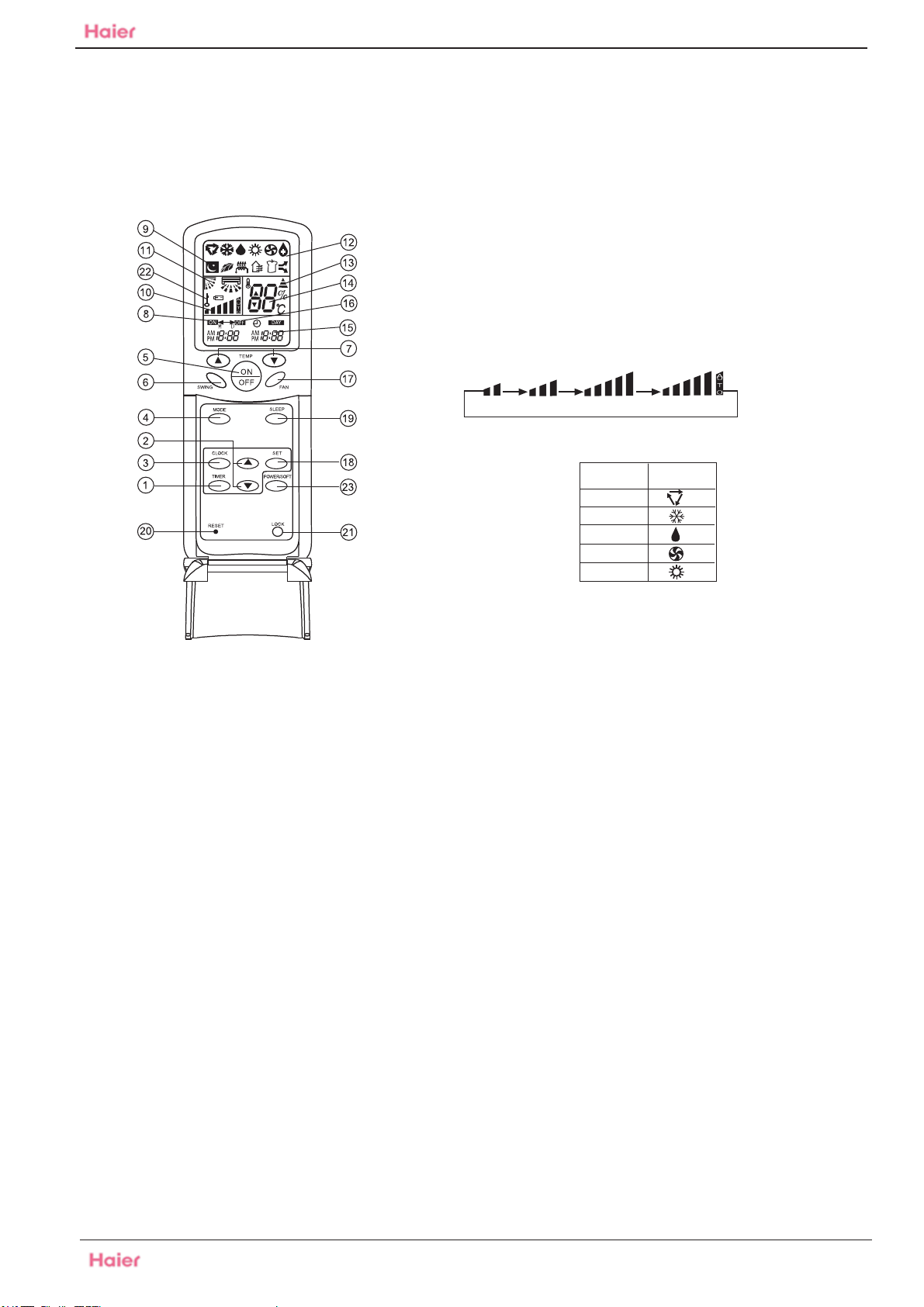
12 Control systems
HFU-09,12,18 HA 03/ R2(DB)
5. ON/OFF
Used for unit start and stop.
6. SWING
Used to adjust the up/down air flow direction.
7. TEMP.
Used to select your desired temperature.
8. TIMER ON display
9. SLEEP display
10. FAN SPEED display
Remote controller:
LOW MED HI AUTO
11. SWING UP/DOWN display
12. MODE display
Operation
mode
AUTO
COOL
DRY
FAN
HEAT
Remote
controller
Control systems
1.TIMER
Used to select TIMER ON,
TIMER OFF, TIMER ON-OFF
2.HOUR
Used to set clock and timer
setting.
3.CLOCK
Used to set correct time.
4. MODE
Used to select AUTO, COOL, DRY,
FAN and HEAT operation.
Note:
1. The following functions and related
displays are not available for all models:
Display of humidifying and atmosphere
humidity.
2. There is health display with the remote
controller in this type, but without health
function.
13. SIGNAL SENDING display
14. TEMP. display
Remote controller: to display the TEMP. setting.
15. CLOCK display
16. TIMER OFF display
17. FAN
Used to select fan speed: LO,MED,HI,AUTO
18. SET
Used to confirm timer and clock settings.
19. SLEEP
Used to select sleep mode.
20. RESET
When the remote controller appears abnormal,
use a sharp pointed item to press this button
to reset the remote controller to normal condition.
21. LOCK
Used to lock buttons and LCD display. If
pressed, the other buttons will be disabled and
the lock condition display appears.
Press it once again, lock will be canceled and
lock condition display disappears.
22. LOCK display
23. POWER/SOFT
39
Domestic air conditioner
Page 42

13 Center of gravity
Indoor
HFU-09,12,18HA03/R2(DB) Center of gravity
720
315
640
305
Outdoor(for 09/12 unit)
783
310
255
120
255
118
543
255
Outdoor(for 18 unit)
680
837
813
275
312
145
332
40
Domestic Air Conditioner
Page 43

14. Installation
HFU-09,12,18HA03/R2(DB) Accessories
mc01n
ah
ter
om
Installation of indoor unit
selection of installation place
Place where it is easy to route drainage pipe
and outdoor piping.
m
o
r
e
t
h
a
n
1
0
c
m
m
o
r
e
t
h
a
n
1
0
c
m
m
c
0
0
1
n
a
h
t
e
r
o
m
Figure.1
Figure.2
Figure.3
Place, away from heat source and with less
direct sunlight.
Place where cool and warm air could be
delivered evently to every corner of the room.
Place near power supply socket.Leave enough
space around the unit.
Place, robust not causing vibration, where the
body can be supported sufficiently.
To prevent interference, place it at least 1m
away from other electric machines, such as
TV set, radio.
Installation
According to the dimension of the Figure 2 shown
nail two cement steel nails on the wall keep 2-3mm
out, then hang the back of the unit on them.
There must be no gap between the indoor unit and
wall.
Remove the front panel,then use two fastening
screws to fix the unit on the floor. As Figure 3 shown.
Once refrigerant piping and drain piping connections
are complete,fill the gap of the through hole with putty.
Attach the front panel and front grille in their orginal
positions once all connections are complete.
Installation of outdoor unit
selection of installation place
more than 10 cm
more than 10 cm
Place strong enough to support the unit and will
not cause vibration and noise.
more than 10 cm
Place where discharged wind and noise does not
cause a nuisance to the neighbors.
Place where is less affected by rain or direct sunlight
and is sufficiently ventilated,or to install a shield.
Place with enough space for smooth air flow.
more than 60 cm
Figure.4
41
Domestic Air Conditioner
Page 44

HFU-09,12,18HA03/R2(DB) The end
Sincere Forever
Haier Group
Haier Industrial Park, No.1, Haier Road Edited by: Zhang Junyan
266101, Qingdao, China
E-mail: hractech@haier.com Signed by:
Tel: +86 532 87636957
Http://www.haier.com
42
Domestic air conditioner
Approved by: Zhang shouxin
Zhang lizhi
 Loading...