

Haier HDU-60CA03T3, HDU-50HT03/H, HDU-42CA03T3/H, HDU-50CA03T3/H, HDU-60CA03T3/H Service Manual
Page 1

Commercial Air Conditioning
SERVICE MANUAL
Models
HDU-50HT03/H
HDU-42CA03T3/H
HDU-50CA03T3/H
HDU-60CA03T3/H
Features
T3 climate
High energy efficiency
Fixed frequency
Long distribution pipe and high drop
Flexible and easy installation
Auxiliary electric heating function (optional)
Optional safety devices and much more precision control device
Weekly timer (standard)
Group control function(Optional)
Auto restart function
Manual code: SYJS-012-08REV.0 Edition: 2008-07-23
Page 2

Commercial Air Conditioner
CONTENTS
Contents………………………………………………………...2
1. Description of products & features………………………..3
2. Specification…………………………………………………5
3. Safety precaution……………………………………………7
4. Net dimension………………………………………………..9
5. Installation instructions………..……………………………10
6. Parts and functions…………………………………………15
7. Controller functions…………………………………………16
8. Electrical control functions…………………………………16
9. Electrical data……………………………………………….31
10. Troubleshooting…………………………………………...34
11. Noise curves..................................................................36
12. Performance curves.......................................................37
2
Page 3

Commercial Air Conditioner
1.DESCRIPTION OF PRODUCTS & FEATURES
1.1. Products code explanation
1.2 Brief Introduction for T1 、T2、T3 working condition
Type of Air
Conditioner
Climate type
T1 T2 T3
Cooling Only
18 ℃~43℃ 10℃~35℃ 21℃~52℃
Heat pump
-7℃~43℃ -7℃~35℃ -7℃~52℃
Electricity Heating
~43℃ ~35℃ ~52℃
1.3 Operating Range of Air Conditioners(for T3 climate)
Temp. Mode Rated Maximum Minimum
Cooling
Indoor
DB ℃
29 32 18
WB ℃
19 23 14
Outdoor
DB ℃
46 52 10
WB ℃
24 31
6
Heating
Indoor
DB ℃
20 27 15
WB ℃
14.5 --- --
Outdoor
DB ℃
7 24 -7
WB ℃
6 18 ---
H D U - 42 C A 03 T3 / H
H:high ESP duct unit;M:middle ESP duct unit
T3:climate type
Power supply type: 03 stands for 200-220V, 50Hz
Design sequence
C: cooling; H: heating
Cooling capacity: 42=42000BTU/h
U: single split unit
Product type : “B” stands for cassette type, “CF” stands for
convertible type, ”D” stands for duct, ”P” stands for cabinet
system,
Haier Brand Air Conditioner
3
Page 4

Commercial Air Conditioner
1.4 Product features
Flexible and easy installation
The outdoor can meet the higher request of installation. From the specifications, you will find for
each unit, how long and how high the piping will be, which will be convenient for design and installation.
High efficiency filter
The unit adopts G3 grade filter, can efficiently filter the dirt etc, and improve the room air quality, at
the same time, the filter can pull out from downside, convenient for maintenance and cleaning.
Multi-mode for installation
The indoor unit can be installed with or without an air return duct according to the installation need.
Free setting of air discharging duct
The number of the airflow outlet and its installation position can be freely selected according to the
environment of the room, sufficiently considering the load of the room and the uniform temperature of the
room to realize more perfect comfort.
High esp design
Max. external static pressure of 196 Pa brings the quick temperature adjustment to the room.
Adopts high pressure fan to provide quich speed of air blowing while keeping a low sound level and
ensuring a good air circulation of the whole indoor space.
Optional safety devices and much more precision control device
a. Ambient temperature sensor, coil temperature sensor and compressor temperature sensor
make the temperature control and defrosting control more precise.
b. High/low pressure switch can feel the discharging pipe pressure and suction pipe pressure on
time and precisely. If the pressure is too low or too high, it will stop the compressor to prevent it
being damaged for the sake of pressure.
c. 3 minutes delay protection for the compressor, the device can protect the compressor from
some damages and make the compressor have a long life.
Group control and Central control if connected with with a group
controller or a central controller
Weekly timing function, if connected with a weekly timer YCS-A001
4
Page 5
Commercial Air Conditioner
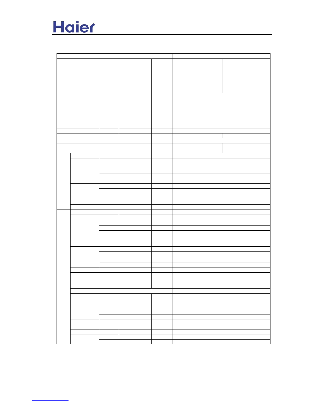
2. SPECIFICATION
Function
coolin
g
heatin
g
Capacity BTU/h
49800 56300
Capacity kW
14.6 16.5
Sensible heat ratio
0.7
W
6540 5830
W
7767 6160
EER or COP
W/W
2.2 2.8
Dehumidifying capacity
10‐³×m³/h
Power cable section
Signal cable section
Connecting cable section
Wired control cable for wired control unit section
Power source N, V, Hz
A / A
Start Current A
Class of anti electric shock
CLASS I CLASS I
Circuit breaker A
Max. operating pressure of heat side Mpa
2.8 2.8
Max. operating pressure of cold side Mpa
2.8 2.8
Unit model (color)
Type × Number
Speed(H-M-L) r/min
Fan motor output power kW
Air-flow(H-M-L) m³/h
Heat exchanger Type / Diameter mm
External
(L×W×H)
mm×mm×mm
Package
(L×W×H)
mm×mm×mm
Control type (Remote /wired /model)
dB(A)
kg / kg
Unit model (color)
Model / Manufacture
Oil model
Oil charging
Type
Protection type
Starting method
Type × Number
Speed r/min
Fan motor output power kW
Air-flow(H-M-L) m³/h
Heat exchanger Type / Diameter mm
External
(L×W×H)
mm×mm×mm
Package
(L×W×H)
mm×mm×mm
Refrigerant control method mm/mm
Noise level dB(A)
crankcase heater power W
kg / kg
Type / Charge g
Recharge quantity g/m
Liquid mm
Gas mm
Connecting Method
m
m
4 x 0.33 mm2
55/52/47
40
64
840
6000
Fan
inner grooved/φ9.52
Fan
Compressor
Inner thermal protection
SCROLL
Defrosting
Automatic
Axial*2
hard startup
Capillary tube
0.06
MAX.Drop
50MAX.Pi
ping
length
Weight (Net / Shipping)
91/111
30
Refrigerant
wired
PIPING
R22/4300
65
Pipe
φ9.52
φ19.05
Flared
Between I.D &O.
Outdoor unit
HDU-50HT03/H(WHITE)
Weight (Net / Shipping)
65/80
Dimension
948*340*1250
1090*410*1350
ZR61KH-TFD-522/COPELAND
SONTEX 200 LT
1656
item Model
HDU-50HT03/H
5.0
5G×2.5mm2
Total power input
Max. power input
Running /Max.Running
centrifugal
Dimension
50
1560~2650
1385×965×418
1197×828×355
inner grooved/φ7
4G×1.5mm2
30
0.27
1110/880/720
3N,380-400V,50HZ
Indoor unit
HDU-50HT03/H(GREY)
Noise level (H-M-L)
Cooling 9.5A/11.3A Heating 9.1/10.35
5
Page 6
Commercial Air Conditioner
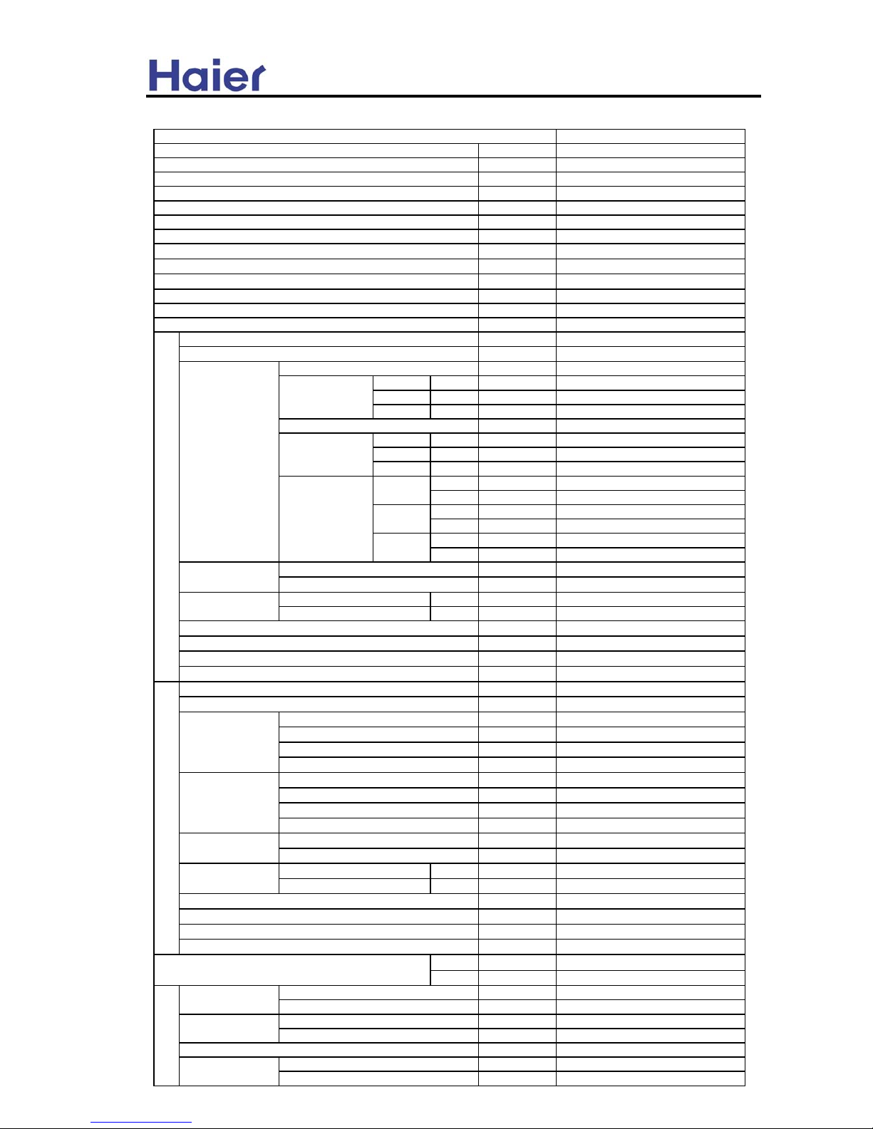
HDU-42CA03T3/H
cooling only
Btu/h
42000(12309W/10584kca/h)
%
80
W
4150
W
5700
W/W
3.0
L/h
3.5
N, V, Hz
3N~,380-415V,50Hz
V
342
V
462
A / A
7.5A /10.0A
A
56
A
30
HDU-42CA03T3/H (GREY)
N, V, Hz
1PH,220-240V,50Hz
centrifugal×2
blue plug
(H-L)
r/min
1215-1050
red plug
(H-L)
r/min
1140-880
white plug
(H-L)
r/min
1050-880
kW
0.45
blue plug H Pa
100
red plug H Pa
80
white plug H Pa
50
0Pa m³/h
H:2950 L: 2400
100Pa m³/h
H:2250 L: 1920
0Pa m³/h
H:2460 L: 1980
80Pa m³/h
H:2250 L: 1720
0Pa m³/h
H:2400 L: 1980
50Pa m³/h
H:2250 L: 1820
mm
9.52
m²
0.452
L×W×H mm×mm×mm 1197×830×350
L×W×H mm×mm×mm 1430×940×420
mm
PVC 26/32
hard wired / YR-E12
dB(A)
54-52
kg / kg
62/70
HDU-42CA03T3/H (WHITE)
N, V, Hz
3N~,380-415V,50Hz
ZR54KS-TFD-522/COPELAND
BLENDED WHITE MINERAL OIL
1242cm³
SCROLL
axial×2
r/min
1000±40
kW
0.23×2
m³/h
6000
mm
9.52
2/1.60
L×W×H mm×mm×mm
948×340×1250
L×W×H mm×mm×mm
1095×415×1400
capillary tubes
L
3.2
dB(A)
60
kg / kg
95/100
Hi MPa
2.85
Lo MPa
1.2
g
R22/3000
g/m
65
mm
Φ9.52
mm
Φ19.05
Flare type
m30
m50
red plug
white plug
Design Pressure
Total air-flow
External
Control type (type/model)
Oil type
Oil charging
Type
Noise level (H-L with blue plug)
Weight (Net / Shipping)
Unit model
Model / Manufacture
Starting Current
item Model
Outdoor unit
Compressor
Fan + motor
Heat exchanger
Dimension
Tube diameter
Face area
Heat exchanger
Power source
Min. Spec. Voltage
Max. Spec. Voltage
Running /Max.Running current
Fan motor input power
Function
Capacity
Sensible heat ratio
Total power input
Max. power input
EER
Dehumidifying capacity
Fan motor input power
Fan + motor
Circuit breaker
Model
Type × Number
Indoor unit
Package
Drainage pipe (material , I.D./O.D.)
Fan speed
Air-flows
Fan motor plugs &
static pressure
blue plug
Gas
PIPING
Refrigerant
Pipe
Between I.D &O.D
Connecting Method
MAX.Drop
Recharge quantity
Liquid
MAX.Piping length
Volume of Accumulator
Noise level
Weight(Net / Shipping)
Type / Charge
Power source
Power source
Package
Refrigerant control method
Diameter
Row / Fin pitch (mm)
Speed
External
Type × Number
Dimension
6
Page 7
Commercial Air Conditioner
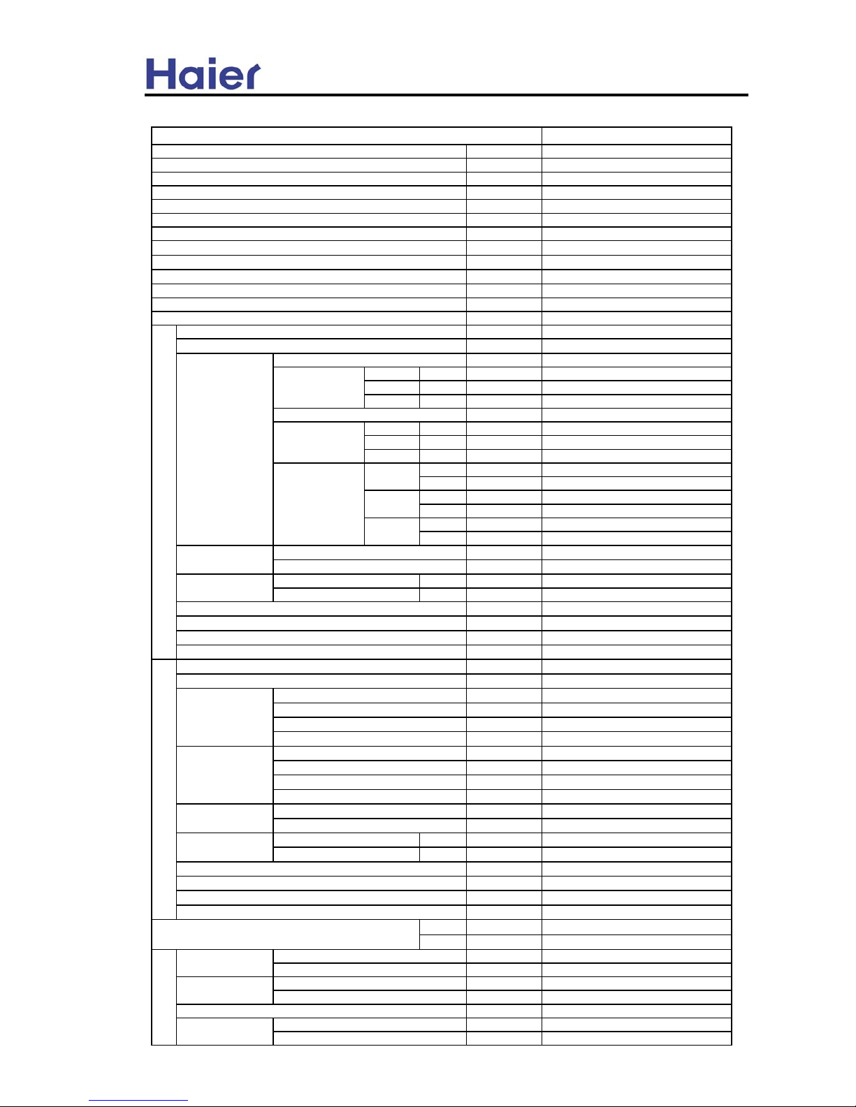
HDU-50CA03T3/H
cooling only
Btu/h
50000(14654W/12600kca/h)
%
77
W
4590
W
6300
W/W
3.2
L/h
4.5
N, V, Hz
3N~,380-415V,50Hz
V
342
V
462
A / A
7.85A /10.5A
A
59
A
30
HDU-50CA03T3/H (GREY)
N, V, Hz
1PH,220-240V,50Hz
centrifugal×2
blue plug
(H-L)
r/min
1215-1050
red plug
(H-L)
r/min
1140-880
white plug
(H-L)
r/min
1050-880
kW
0.45
blue plug H Pa
100
red plug H Pa
80
white plug H Pa
50
0Pa m³/h
H:2950 L: 2400
100Pa m³/h
H:2250 L: 1920
0Pa m³/h
H:2460 L: 1980
80Pa m³/h
H:2250 L: 1720
0Pa m³/h
H:2400 L: 1980
50Pa m³/h
H:2250 L: 1820
mm
9.52
m²
0.452
L×W×H mm×mm×mm 1197×830×350
L×W×H mm×mm×mm 1430×940×420
mm
PVC 26/32
hard wired / YR-E12
dB(A)
54-52
kg / kg
62/70
HDU-50CA03T3/H (WHITE)
N, V, Hz
3N~,380-415V,50Hz
ZR61KS-TFD-522/COPELAND
BLENDED WHITE MINERAL OIL
1242cm³
SCROLL
axial×2
r/min
1000±40
kW
0.23×2
m³/h
6000
mm
9.52
2/1.60
L×W×H mm×mm×mm
948×340×1250
L×W×H mm×mm×mm
1095×415×1400
capillary tubes
L
3.2
dB(A)
60
kg / kg
99/104
Hi MPa
2.85
Lo MPa
1.2
g
R22/3400
g/m
65
mm
Φ9.52
mm
Φ19.05
Flare type
m30
m50
Design Pressure
item Model
Function
Capacity
Sensible heat ratio
Total power input
Max. power input
EER
Dehumidifying capacity
Power source
Fan motor plugs &
static pressure
Air-flows
Min. Spec. Voltage
Max. Spec. Voltage
Running /Max.Running current
Starting Current
blue plug
red plug
white plug
Heat exchanger
Tube diameter
Face area
Circuit breaker
Indoor unit
Model
Fan + motor
Type × Number
Fan speed
Fan motor input power
Dimension
External
Package
Drainage pipe (material , I.D./O.D.)
Control type (type/model)
Noise level (H-L with blue plug)
Weight (Net / Shipping)
Outdoor unit
Unit model
Compressor
Model / Manufacture
Oil type
Oil charging
Type
Package
Fan + motor
Type × Number
Speed
Fan motor input power
Total air-flow
Row / Fin pitch (mm)
Dimension
External
Between I.D &O.D
Refrigerant control method
Volume of Accumulator
Noise level
Weight (Net / Shipping)
MAX.Drop
MAX.Piping length
PIPING
Pipe
Liquid
Gas
Connecting Method
Power source
Power source
Refrigerant
Type / Charge
Recharge quantity
Heat exchanger
Diameter
7
Page 8
Commercial Air Conditioner
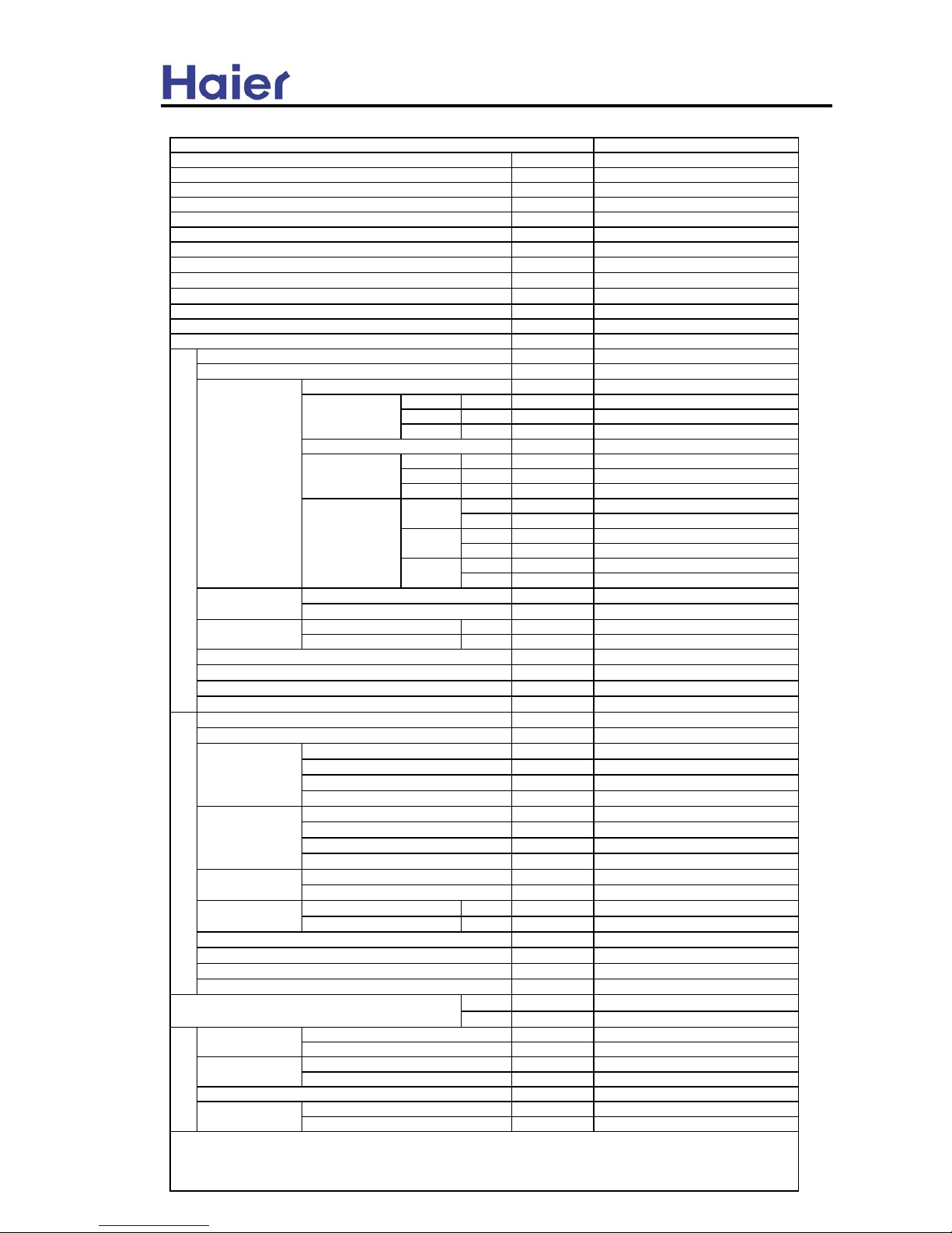
HDU-60CA03T3/H
cooling only
Btu/h
57000(16705W/14364kca/h)
%
73
W
5200
W
7000
W/W
3.2
L/h
5.5
N, V, Hz
3N~,380-415V,50Hz
V
342
V
462
A / A
9.0.A /13.3A
A
74
A
30
HDU-60CA03T3/H (GREY)
N, V, Hz
1PH,220-240V,50Hz
centrifugal×2
blue plug
(H-L)
r/min
1210-1050
red plug
(H-L)
r/min
1150-880
white plug
(H-L)
r/min
1050-880
kW
0.45
blue plug H Pa
100
red plug H Pa
80
white plug H Pa
50
0Pa m³/h
H:2950 L: 2400
100Pa m³/h
H:2250 L: 1920
0Pa m³/h
H:2460 L: 1980
80Pa m³/h
H:2250 L: 1720
0Pa m³/h
H:2400 L: 1980
50Pa m³/h
H:2250 L: 1820
mm
9.52
m²
0.452
L×W×H mm×mm×mm 1197×830×350
L×W×H mm×mm×mm 1430×940×420
mm
PVC 26/32
hard wired / YR-E12
dB(A)
54-52
kg / kg
62/70
HDU-60CA03T3/H (WHITE)
N, V, Hz
3N~,380-415V,50Hz
ZR68KC-TFD-522/COPELAND
BLENDED WHITE MINERAL OIL
1774cm³
SCROLL
axial×2
r/min
1000±40
kW
0.23×2
m³/h
6000
mm
9.52
2/1.60
L×W×H mm×mm×mm
948×340×1250
L×W×H mm×mm×mm
1095×415×1400
capillary tube+piston throttle (102#)
L
3.2
dB(A)
60
kg / kg
106/111
Hi MPa
2.85
Lo MPa
1.2
g
R22/4000
g/m
65
mm
Φ12.7
mm
Φ19.05
Flare type
m30
m50
Norminal condition: indoor temperature (cooling): 29 ℃DB/19℃WB, Outdoor temperature(cooling): 46℃DB/24℃WB,
The noise level will be measured in the third octave band limited values, using a Real Time Analyser calibrated sound intensity meter. It
is a sound pressure noise level. The detailed method please refer to the following information:
Design Pressure
item Model
Function
Capacity
Sensible heat ratio
Total power input
Max. power input
EER
Dehumidifying capacity
Fan motor input power
Fan motor plugs &
static pressure
Air-flows
Power source
Min. Spec. Voltage
Max. Spec. Voltage
Running /Max.Running current
blue plug
red plug
white plug
Heat exchanger
Tube diameter
Face area
Starting Current
Circuit breaker
Indoor unit
Model
Fan + motor
Type × Number
Fan speed
Dimension
External
Package
Drainage pipe (material , I.D./O.D.)
Control type (type/model)
Noise level (H-L with blue plug)
Weight (Net / Shipping)
Outdoor unit
Unit model
Compressor
Model / Manufacture
Oil type
Oil charging
Type
Package
Fan + motor
Type × Number
Speed
Fan motor input power
Total air-flow
Row / Fin pitch (mm)
Dimension
External
Between I.D &O.D
Refrigerant control method
Volume of Accumulator
Noise level
Weight (Net / Shipping)
MAX.Drop
MAX.Piping length
PIPING
Pipe
Liquid
Gas
Connecting Method
Power source
Power source
Refrigerant
Type / Charge
Recharge quantity
Heat exchanger
Diameter
8
Page 9

Commercial Air Conditioner
Installation state: the unit should be placed on the flat floor or be mounted in horizontal
direction.
Testing method:
duct unit without auxiliary duct: duct unit with auxiliary duct:
1.4m
2m
duct
auxiliary duct
2m
1.4m
1m
auxiliary duct
outdoor unit:
1.air outlet from side: the noise level is the average sound pressure level measured from front, left, right directions.
2.air outlet from top: the noise level is the average sound pressure level measured from front, back, left, right directions.
measured point:
H ( height to the ground) = (h (unit height) + 1m) /2
and, it is 1m to each side.
h
1m
1m
1m
1m
Note: ⊙ is the real time
analyser position
9
Page 10
Commercial Air Conditioner
3. Safety precaution
Carefully read the following information in order to operate the airconditioner correctly.
Below are listed three kinds of Safety Cautions and Suggestions.
WARNING!
Incorrect operations may result in severe consequences of death or serious injuries.
CAUTION!
Incorrect operations may result in injuries or machine damages; in some cases may
cause serious consequences.
INSTRUCTIONS: These information can ensure the correct operation of the machine.
Be sure to conform with the following important Safety Cautions.
The Safety Cautions should be at hand so that they can be checked at any time when needed.
If the conditioner is transferred to the new user, this manual should be as well transferred to the new user.
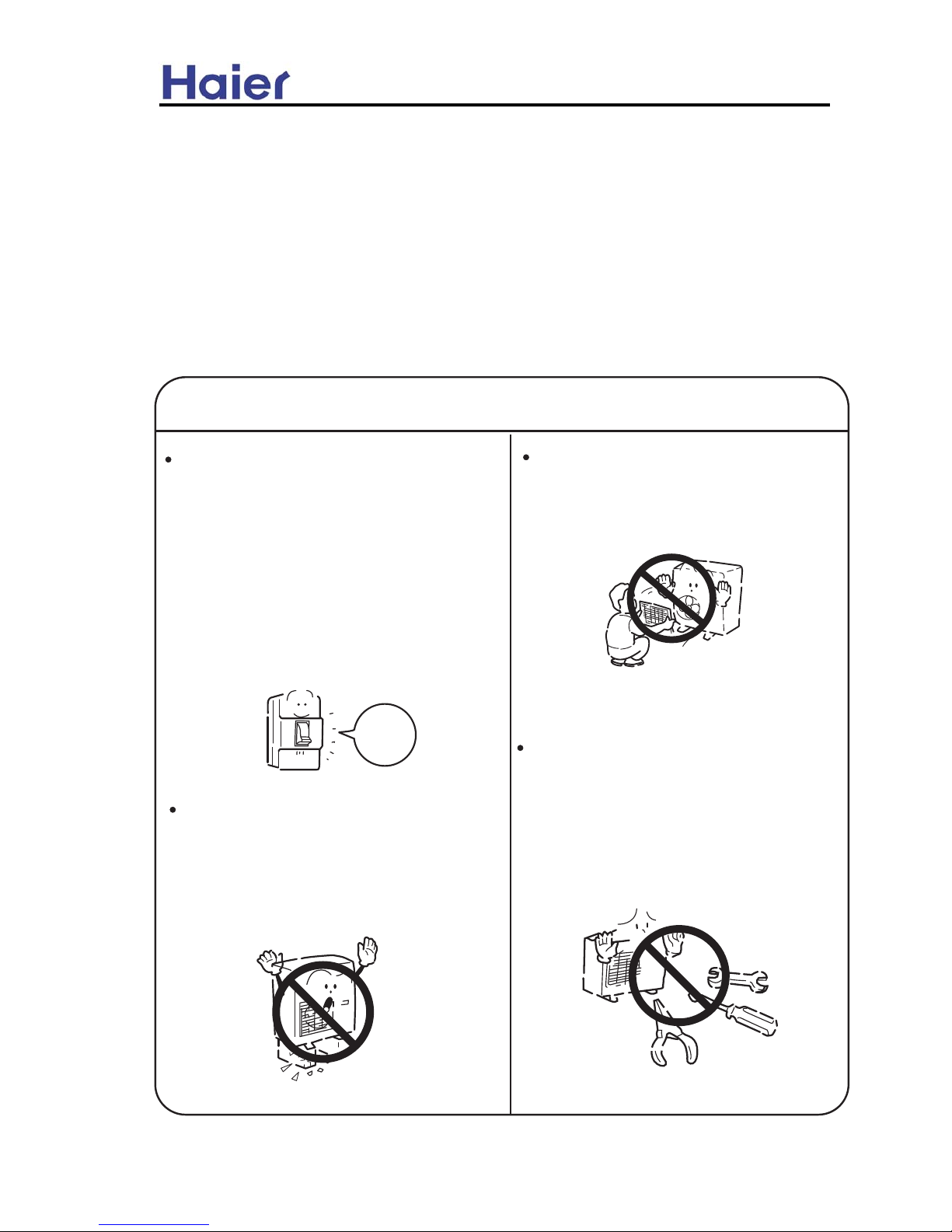
WARNING!
If any abnormal phenomena is found
(e. g.smell of firing), please cut off the
power supply immediately, and contact
the dealer to find out the handling
method.
Don't dismantle the outlet of the
outdoor unit.
The exposure of fan is very dangerous
whichmay harm human beings.
switch
off
In such case, to continue using the
conditioner will damage the conditioner,
and may cause electrical shock or fire
hazard.
Incorrect maintenance and repairment
may cause water leak, electrical shock
and fire hazard.
When need maintenance and repairment,
call dealer to handle it.
After a long time use of air-conditioner
the base should be checked for any
damages.
If the damaged base is not repaired, the
unit may fall down and cause accidents.
10
Page 11

Commercial Air Conditioner
Air-conditioner can't be installed in
the environment with inflammable
gases because the inflammable gases
near to air-conditioner may cause fire
hazard.
Connect earthing wire.
Use discharge pipe correctly to ensure
efficient discharge.
Earthing wire should not be connected to the gas pipe, water pipe,
lightning rod or phone line, in-correct
earthing may cause shock.
Incorrect pipe use may cause water
leaking.
Earthing
WARNING!
Installed electrical-leaking circuit
breaker.
It easily cause electrical shock without
circuit breaker.
Please let the dealer be responsible for
installing the conditioner.
Incorrect installation may cause water
leak, electrical shock and fire hazard.
Call the dealer to take measures to
prevent the refrigerant from leaking.
If conditioner is installed in a small
room be sure to take every measure in
order to prevent suffocation accident
even in case of refrigerant leakage.
When conditioner is deinstalled or
reinstalleddealer should be responsible
for them.
Incorrect installation may cause water
leaking, electrical shock and fire hazard.
No goods or nobody is permitted to
placed on or stand on outdoor unit.
The falling of goods and people may
cause accidents.
Don't operate the air-conditioner with
damp hands.
Otherwise will be shocked.
Only use correctly-typed fuse.
May not use wire or any other materials
replacing fuse, other-wise may cause
faults or fire accidents.
11
Page 12
Commercial Air Conditioner
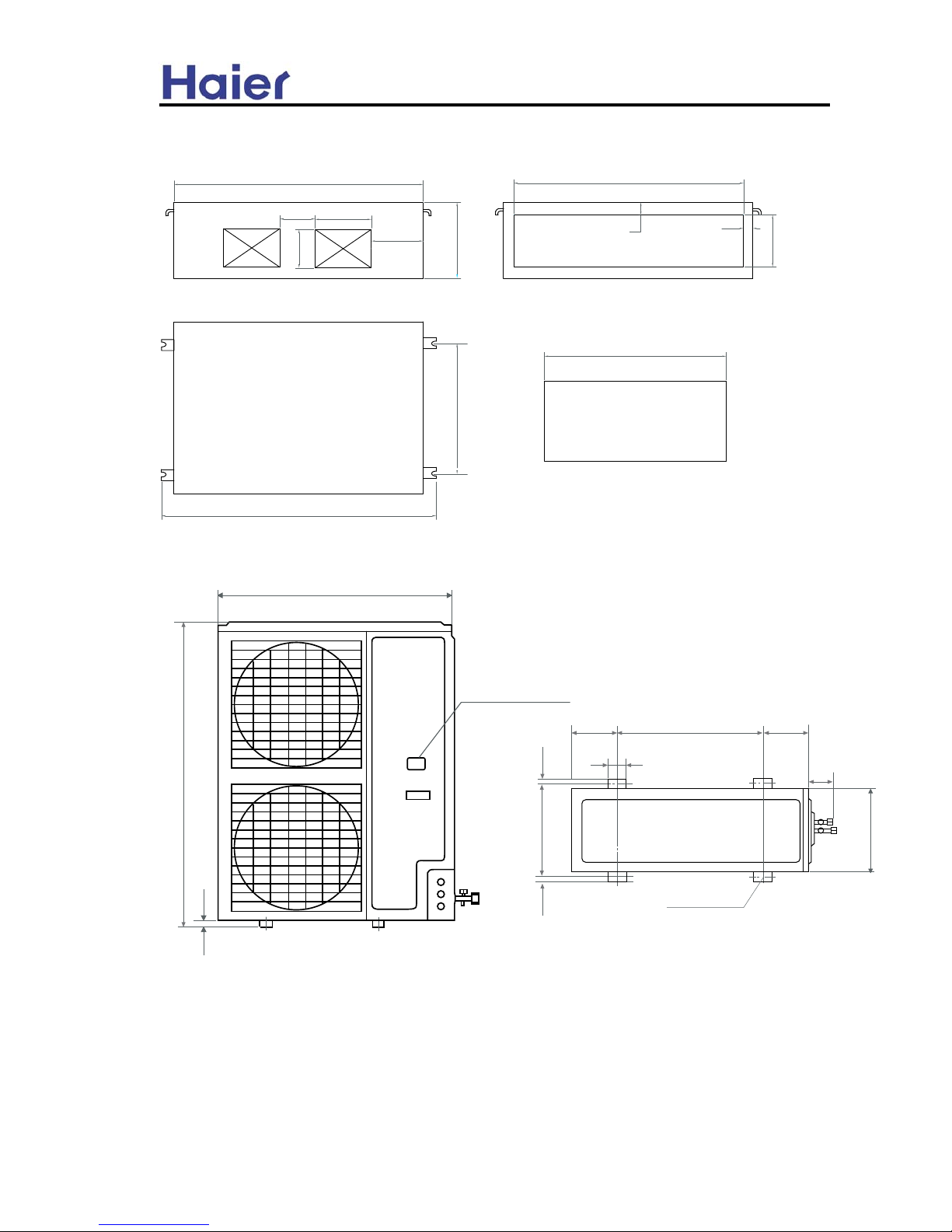
4. Net dimension
1105
1200
170 270
250
365
185
250
60
45
800
1320
830
(mm)
948
1250
25
Power wiring Terminal
184 184
55
Screw Hole
580
70
380
18
340
18
(4xM10)
12
Page 13

NO
L1
500
Commercial Air Conditioner
5. Installation Instructions
5.1 Outdoor unit installation
1. Accessories
"Edging" for protection of electric wires from an
opening edge.
2. Selection of the place of installation
Edging
Select the place of installation satisfying the following conditions and, at the
same time, obtain a consent from the client or user.
Place where air circulates.
Place free from heat radiation from other heat sources.
Place where drain water may be discharged.
Place where noise and hot air may not disturb the neighborhood.
Place where there is not heavy snowfall in the winter time.
Place where obstacles do not exist near the air inlet and air outlet .
Place where the air outlet may not be exposed to a strong wind.
Place surrounded at four sides are not suitable for installation. A 1m or more
of overhead space is needed for the unit.
Mount guide-louvers to place where short-circuit is a possibility.
When installing several units, secure sufficient suction space to avoid short
circuiting.
(1) Open space requirement around the unit
Air inlet
L3
(Servicing
inlet
space)
Air outlet
L2
Air
Note :
(1). Fix the parts with screws
(2).Don't intake the strong wind directly to the
outlet air-flow hole.
(3).A one meter distance should be kept from the
unit top
(4).Don't block the surroundings of the unit with
sundries
Unit: mm
Case
Distance
open
open
open
500
150
150
300
300
0
L1
L2
L3
I
II
III
Wind direction
(2) Installation where the area with strong winds.
Install the unit so that the air outlet section of the unit must NOT be faced
toward wind direction.
13
Page 14
Commercial Air Conditioner
3. Installation of outdoor unit
(1) Installation
Fix the unit in a proper way according to the condition of a place where it is
installed by referring to the following .
(a) Concrete foundation (b) Foundation anchor
Unit
To fix by bolts
Anchor bolt
Concrete foundation
Unit
Concrete foundation
Anchor bolt
Note: (1) Give enough room for the concrete
foundation to fix by anchor bolts.
Note: (1) Place the concrete foundation deep enough.
Install the unit so that the angle of inclination must be less than 3 degrees.
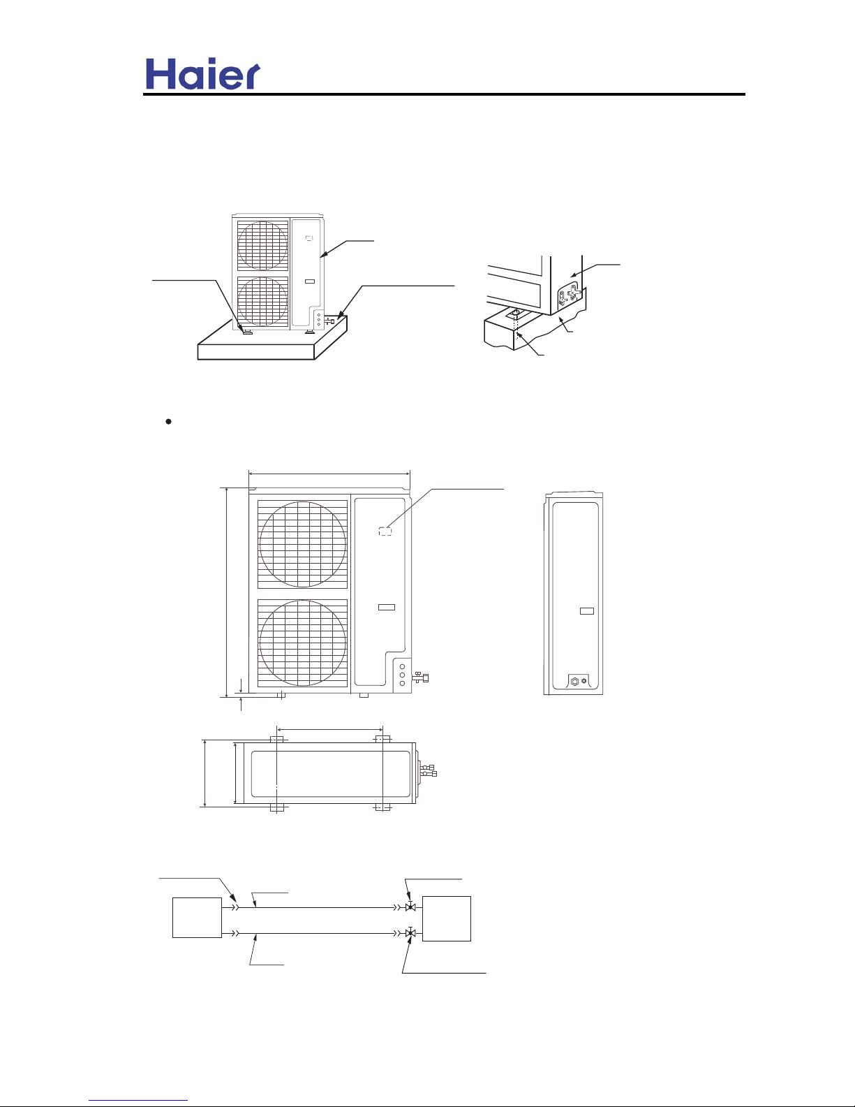
(2) Installation sketch of outdoor unit
340
580
380
948
Power wiring Terminal
25
1250
4. Refrigerant piping
Flare connection
3-way stop valve
Outdoor
unit
Gas pipe
Liquid
pipe
Indoor
unit
2-way stop valve
14
Page 15

Y/G
Commercial Air Conditioner
Piping size
Install the removed flare nuts to
90+0.5
Gas pipe
9.52x0.8mm
19.05x1.0mm
Liquid pipe
HDU-50HT03/H
the pipes to be connected, then
flare the pipes.
Limitations for one way piping length and vertical height difference.
Model
One way piping length
Vertical height difference
(between indoor and outdoor)
less than 50 m
less than 30 m
HDU-50HT03/H
The detail information please refer to the installation manual.
Selection of size of power supply and interconnecting wires.
Select wire sizes and circuit protection from table below. (This table shows 20 m length
wires with less than 2% voltage drop.)
Item
Circuit breaker
Power
Earth leakage breaker
Model
Phase
Switch breaker
(A)
Overcurrent
protector
source wire
size
Switch
break
Leak
curren
HDU-50HT03/H
3
30 20
2.5mm
2
30
30mA
Wiring connection
N 1 2 3
Y/G
R S T
POWER SUPPLY:
To Indoor Unit
3N~,380-400V,50Hz
Gas pipe
Liquid pipe
Gas pipe
9.52x0.8mm
12.7x0.8mm
19.05x1.0mm
Liquid pipe
19.05x1.0mm
HDU-42CA03T3/H
HDU-50CA03T3/H
HDU-60CA03T3/H
HDU-42CA03T3/H
HDU-50CA03T3/H
HDU-60CA03T3/H
Model
One way piping length
Vertical height difference
(between indoor and outdoor)
less than 50 m
less than 30 m
it is also apply to HDU-42CA03T3/H,HDU-50CA03T3/H,
HDU-60CA03T3/H
15
Page 16

Hint
Siz
wire
wire
Commercial Air Conditioner
5.2 Indoor unit installation
1. Remove upper part of wire controller
Remove upper part of wire controller
PCB is mounted on lower part of wire controller, be careful not to damage it.
Upper part of wirecontroller
2. Install wire controller
(1) For exposed installation, use 2 wood screws .
(2) For recessed installation, use 2 wood screws .
Lower part of wire
controller
Note:
Try as far as possible a flat surface for installation. Don't use excessive force when
tightening screws, or lower part might got deformed.
3. Indoor unit wiring
Connect terminals (A,B,C,D) on lower part of wire
When make wiring, please
controller to terminals (A, B,C,D) on PCB of indoor
keep a distance between
unit.
wires and power supply cord.
wiring from here
Wire
AB CD
Lower part of
Cord kind
Shield wire (4 core) (refer to Hint
0.33mm
2
Use shielede wires for telecommunication between
wire controller and indoor unit; indoor unit and
outdoor unit. Ground the shield on one side.
Otherwise misoperation because of noise may occur.
Signal wire is self-provided.
Upper part of
ground
Shielded wire
16
Page 17

Hint
Hint
Commercial Air Conditioner
Tread surface of the terminal well so that shielding may not contact other part.
4. Replace the upper part of wire controller
Be careful not to press the wiring.
1. Switch box and cord for wiring are not supplied.
2. Don't touch PCB with hand.
Change-over switch
Mark
ON
OFF
1
Fixed Frequency Inverter
2
Have rise and drop No rise and drop
3
Swing Not Swing
4
The collection
temperature of
indoor unit
The collection
temperature of wire
controller.
For
HDU-50HT03/H
, change-over switch is set:
1. ON 2.OFF 3.OFF 4.OFF
The detail information please refer to the installation manual.
5. Electric wiring
WARNING
DANGER OF BODILY INJURY OR DEATH
TURN OFF ELECTRIC POWER AT CIRCUIT BREAKER OR POWER SOURCE BEFORE
MAKING ANY ELECTRIC CONNECTIONS. GROUND CONNECTIONS MUST BE
COMPLETED BEFORE MAKING LINE VOLTAGE CONNECTIONS.
(1) Selection of size of power supply and interconnecting wires.
Precautions for Electric wiring
Electric wiring work should be conducted only by authorized personnel.
Do not connect more than three wires to the terminal block. Always use round type crimped
terminal lugs with insulated grip on the ends of the wires.
Use copper conductor only.
Select wire sizes and circuit protection from table below. (This table shows 20 m length
wires with less than 2% voltage drop.)
Item
Circuit breaker
Power
Earth leakage breaker
Model
Phase
Switch breaker
(A)
Overcurrent
protector
source wire
size
Switch
break
Leak
curren
HDU-50HT03/H
3
30 20 2.5mm
2
30 30mA
(2) Wiring connection
Make wiring to supply power to the outdoor unit, so that the power for the indoor unit is supplied by
terminals.
N 1 2 3R S T
Y/G
1 2 3
POWER SUPPLY:
Y/G
3N~,380-400V , 50Hz
INDOOR UNIT TERMINAL BLOCK
it is also apply to HDU-42CA03T3/H,HDU-50CA03T3/H,
HDU-60CA03T3/H
17
Page 18

Commercial Air Conditioner
6. Parts and Functions
XZXUJSINSL UTQJ
LZFWINSL UQFYJ
J[FUTWFYTWnNSXNIJo
IZHY
IWFNS UNUJ
JQJHYWNH GT]
XYTU [FQ[J
XZXUJSINSL GTQY
DLU LQOHW
DLU RXWOHW
FRPSUHVVRUnLQVLGH RI XQLWo
VWRS YDOYH
18
Page 19

Commercial Air Conditioner
7.Refrigerant circuit
19
Page 20

Commercial Air Conditioner
8. Controller functions
For HDU-50HT03/H,HDU-42,50,60CA03T3/H, the indoor unit can be controlled by wired controller
YR-E06.
9. Electrical Control Functions
9.1 For indoor unit
1. General notes for the function
1.1 The electric system can control the following functions of the commercial air conditioner.
Operation mode includes auto run, cooling, dehumidifying, venting, and heating. It can set the
compulsory cooling, and indoor fan motor has auto, high, med, low three selection. And it can set
TIMER ON, TIMER OFF, TIMER ON/OFF and SLEEP; auto check water level in the container and
control the drainage; swing controlled by synchro-motor; equipped with compressor 3-minutes
protection; overload protection; freezing protection; sensor broken down protection, etc. Also it can
check communication failure and measure indoors room temperature, indoor coil temperature.
Operation panel adopts LCD display, receiving the indication by pressing buttons, and it can realize
remote control function, also is responsible to measure indoor room temperature and it adopts
serial communication type with main board.
1.2 LED indication: when the unit is switched on by the controller, the POWER LED will be ON,
when being switched off, the POWER LED will be OFF. If the controller is in TIMER and SLEEP
mode, the TIMER LED will be on; if it is not in TIMER and SLEEP mode, the TIMER LED will be off.
When the compressor is running, the compressor LED will be on; when it stops, this LED will be off.
1.3 Temperature compensation control: select the 4 degree compensation when use ambient
temperature sensor on the indoor PCB( include: remote control type and wired control type use
indoor ambient temperature sensor).
1.4 There is set temperature in AUTO mode as default.
1.5 Do not receive the remote OFF signal when enter defrost mode.
2. Control modes selection
2.1 Auto fan speed selection
The following Tr stands for room temperature, Ts stands for set temperature.
2.1.1 In cooling mode
If it is the first time to enter auto fan mode(fan motor is stop), when Tr>Ts+2, it is in High speed; Tr
≤Ts, it is in Low speed; Otherwise, it is in Med speed. If the current mode is auto high speed, when
Tr<Ts+2, fan speed will turn to med speed automatically. If the current mode is auto med speed,
when Tr>Ts+3, it will turn to high speed, Tr<Ts,
it will turnto
low speed.
If current
mode is low
Temp. reducing
Med
Ts +2℃
High
Ts +3℃
High
speed, when
Ts +1℃
Med
Tr>Ts+1, it
will turn to med
Ts
Low
speed. When fan
Low
speed changes from low to
Temp. arising
20
Page 21

Commercial Air Conditioner
high, current mode will continue running 3 minutes and then turn to high speed. But nor while the
mode change from high to low.
2.1.2 In heating mode(Cooling only unit without this function)
Wired type units: If it is the first time to enter auto fan mode(fan motor is stop), when Tr>Ts-1, it is
in Low speed; Tr≤Ts-3, it is in High speed; Otherwise, it is in Med speed. If the current mode is
auto low speed, when Tr<Ts-1, fan speed will turn to med speed. If the current mode is auto med
speed, when Tr>Ts, it will turn to low speed, Tr>, it will turn to high speed, If the current mode is
high speed, when Tr>Ts-2, it will turn to med speed. (Ts is the set temperature in the wired
controller)
When fan speed changes from low to high, current mode will continue running 3 minutes and then
turn to high speed. But nor while the mode change from high to low.
Temp. reducing
Low
High
Ts
Med
Ts -1℃
Med
T
s-2℃
High
arising
Te mp .
Low
Remote type units: If it is the first time to enter auto fan mode, when Tr>(Ts+4)-1, it is in Low
speed; Tr≤(Ts+4)-3, it is in High speed; Otherwise, it is in Med speed. If the current mode is auto
low speed, when Tr<(Ts+4)-1, fan speed will turn to med speed automatically. If the current mode
is auto med speed, when Tr>Ts+4, it will turn to low speed, when Tr<(Ts+4)-3, it will turn to high
speed. If current speed is high, when Tr>(Ts+4)-2, it will turn to med speed. (Ts is the set
temperature in the remote controller)
When fan speed changes from low to high, current mode will continue running 3 minutes and then
turn to high speed. But nor will the mode change from high to low.
Please refer to the sketch map:
Temp. reducing
Low
High
(Ts+4)
Med
(Ts+4)-1
(Ts+4)-2
Med
(Ts+4)-3
High
Low
arising
Te mp .
2.2 Auto run
a. Heat pump unit
After starting up, operation mode turns to auto run; system will decide the operation mode
according to the difference in current setting temperature and room temperature. Tr stands for room
21
Page 22

-3
Commercial Air Conditioner
temperature, Ts stands for setting temperature.
When it is the first time to auto run, operation mode will be selected according to the following
conditions:
Tr>Ts select cooling mode
Tr=Ts select blowing mode(compressor stopped when in cooling mode)
Tr<Ts select heating mode
After the system enters auto run mode, the running mode can convert automatically according to
variation of room temperature between cooling and heating in the way shown as the chart below: If
the current mode is cooling, when it arrive at the compressor stop temperature, the compressor will
stop; after 3 minutes, the unit measure the temperature again, at this time, if Tr<Ts- 3℃, it will enter
heating mode, or it will still be in cooling mode; if the current mode is heating, when it arrive at the
compressor stop temperature, the compressor will stop, after 3 minutes, the unit will measure the
room temperature, if Tr>Ts+ 3℃, it will enter cooling mode, or it will still be in heating mode.
When system is in heating, if temperature of indoor heat exchanger is more than 63℃, the unit will
convert to cooling mode automatically, within 1 hour the temperature of indoor heat exchanger will
not be limited; heating operation stop, after 1 hour, the unit will select the right mode according to
the above conditions.
When it is the first time to select heating, compressor and outdoor fan motor start up, within 8
minute it will not measure indoor room temperature. The conversion chart is below:
Temp. reducing
cooling
Ts +3 ℃
cooling
blowing
Temp. arising
Ts -3 ℃
Ts
Ts -3℃℃
heating
heating
b. Cooling only unit
When it is the first time to auto run, operation mode will be selected according to the following
conditions:
Tr≥Ts + 3 ℃ select cooling mode
Tr<Ts + 3 ℃ select blowing mode
After the system enters auto run mode, the running mode can convert automatically according to
variation of room temperature between cooling and blowing in the way shown as the chart below: If
the current mode is cooling, when Tr<Ts - 3 ℃, it will turn to blowing; if the current mode is blowing,
when Tr≥Ts + 3 ℃, it turns to cooling mode. The conversion is the below chart:
Temp. reducing
heating
Ts+3 ℃
blowing
cooling
Ts-3 ℃
blowing
Temp. arising
22
Page 23

压机开
压机关
Commercial Air Conditioner
Room temperature is controlled by the set temperature ( control precise is +1℃).
Fan blade can select swing or stay in one position; fan speed can be low, med, high or auto speed.
Also timer or sleep can be set.
2.3 Cooling operation
2.3.1 The solenoid valve is powered off, the controller determines compressor run/stop according
to the difference between current room temperature and set temperature.
Tr≥Ts+1 compressor run
Tr≤Ts-1 compressor stop
Ts-1<Tr<Ts+1 compressor in original state Refer to the below chart:
Temp. reducing
compressor run
Ts +1
Ts -1
compressor stop
Temp. arising
2.3.2 Anti-current rush: 1.6 seconds later after compressor is running, outdoor and indoor motor
can work.
2.3.3 Freeze protection
After the compressor has run for 6 minutes, If the temperature of indoor coil pipe Ticp < 1℃ and it
keep 1 minute, the compressor and outdoor fan motor will stop and change to blowing mode. They
will run again after the compressor stops if both the following conditions are meeted:
1) 9 minutes have passed since compressor stops.
2) Ticp exceeds 10℃
2.3.4 Temperature cutoff protection
For 2HP units: If indoor coil temperature Ticp > 68℃ and it keep 10 seconds, compressor and
outdoor motor will stop. After compressor stops, if Ticp < 48℃ and compressor stop more than 9
minutes, the compressor and outdoor motor will resume to run normally.
For 3HP and 5HP units: After compressor running for 9 minutes, indoor unit will check the indoor
coil temperature (Ticp) and send to outdoor. If Ticp > 68℃ and it keep 10 seconds, indoor will send
the signal of stop compressor to outdoor. After compressor stops, if Ticp < 48℃ and compressor
stop more than 9 minutes, indoor will send the signal to start up compressor, and the compressor
will resume to run normally. Outdoor fan motor is controlled by outdoor.
2.3.5 Current peak value protection
For controller of 3HP and 5HP single chip units, controlled by outdoor unit.
For 2HP units, when CT current is more than I3(21A) and lasts for 3 seconds after compressor has
run for 60 seconds, compressor and outdoor motor will stop. After compressor stops 3 minutes, the
compressor and outdoor motor will resume to run normally.
2.4 Dehumidification operation
a. When it is the first time to dehumidify, compressor, outdoor fan motor, indoor fan motor will
operate according to below rules:
23
Page 24

Commercial Air Conditioner
(1). Tr>Ts+2℃, compressor, outdoor fan motor continue running, while indoor fan motor runs at
set fan speed. This working area is defined as area A.
(2). Ts≤Tr≤Ts+2℃, the compressor and outdoor fan motor run for 10 minutes then pause for 6
minutes, while indoor blowing fan runs at low speed. This working area is defined as area B.
(3). Tr < Ts, the compressor and outdoor fan motor stop working while outdoor blowing fan runs at
low speed. This working area is defined as area C.
b. After dehumidifying program starting, the system converts between A, B and C areas according
to variations of room temperature with running mode. If working in area A, when Tr<Ts+1, it
converts to area B; If working in area C, when Tr > Ts, it converts to area B; If working in area B,
when Tr>Ts+3, it converts to area A, and Tr<Ts-1, it converts to area C. The conversion is shown
as the chart below:
Temp. reducing
Area A
Area A
Ts +3
Ts +1
Area B
Area B
Ts
Ts -1
Area C
Area C
Temp. arising
c. Freeze protection
After the compressor has run for 6 minutes, If the temperature of indoor coil pipe Ticp< 1℃, the
compressor and outdoor fan motor will stop and change to blowing mode. They will run again after
the compressor stops if both the following conditions are meeted:
1) 9 minutes have passed since compressor stops.
2) Ticp exceeds 10℃
d. Overheat protection
2.5 Blowing operation
Outdoor fan motor and compressor stop, and indoor fan speed can be set as high, med or low. Fan
blade can be set swing or stay in one position. Also it can set timer or sleep and high voltage
removing dirt or fresh air function.
2.6 Heating operation(Cooling only unit without this function)
2.6.1 Wired type unit
a. 4-way valve control: enter heating mode and compressor starts up; 4-way valve is on. If in
heating mode, compressor stop, 4-way valve will stop after 2 minutes. If it is from heating mode to
other mode, compressor will stop firstly,
after 2 minutes 4-way valve stop, too.
b. The first time to heating mode,
compressor and outdoor fan motor start
Temp. reducing
compressor stop
Ts +1
up, the controller determines compressor
run/stop according to the difference
between current room temperature and
Ts -1
Temp. arising
set temperature.
compressor run
24
Page 25

Commercial Air Conditioner
Tr≥Ts+1 compressor stop
Tr≤Ts-1 compressor run
Ts-1<Tr<Ts+1 compressor in original state
2.6.2 Remote type units:
a. 4-way valve control: enter heating mode and compressor starts up; 4-way valve is on. If in
heating mode, compressor stop, 4-way valve will stop after 2 minutes. If it is from heating mode to
other mode, compressor will stop firstly, after 2 minutes 4-way valve stop, too.
b. The first time to heating mode, compressor and outdoor fan motor start up, after 8 minutes,
system will check the indoor room temperature, the controller determines compressor run/stop
according to the difference between current room temperature and set temperature. Every starting
up, it will not be affected by indoor room temperature within 8 minutes. The remote controller can
release 8-minute limit.
Ts stands for set temperature in remote controller, Tr stands for current room temperature, △
Tstands for compensation temperature. So:
Tr≥(Ts + 4)+△T + 1 compressor stop
Tr≤(Ts + 4)-1 compressor run
(Ts +4 )- 1 <Tr<(Ts+ 4 )+△T + 1 compressor in original state
Temp. reducing
compressor stop
(Ts +4 +△T)+1
compressor run
(
Ts +4)-1
Temp. arising
In heating mode, there is auto temperature compensation, whose condition is compressor achieve
the temperature condition and the time < 5 minutes from the compressor shut off to the compressor
start up again. The rule is below:
A. △T=Ts-Tr (compressor start up)
B. If Ts-Tr≥2℃, △T=2℃; If Ts-Tr=1℃, △T=1℃; If Ts-Tr≤0℃, △T=0℃。
C. With compensation, if pressing the temperature reducing button of remote controller, △T=0℃; if
pressing the temperature increasing button, △T will remain the original value.
Anti-current rush: 1.6 seconds later after compressor is running, outdoor and indoor motor can
work.
Outdoor fan motor and compressor will open and close simultaneously (except for overheating),
indoor fan speed can be set high, med, low, auto. And the air blade can swing or stay in one
position. Also it can be set timer or sleep.
2.6.3 Overheat protection (for the unit with outdoor communication, the outdoor motor is
controlled by outdoor unit, but the compressor is still controlled by indoor unit, and their temperature
points will not be accordant completely)
In heating mode, compressor has started up and indoor motor has run for over 30 seconds, if indoor
coil temperature Tg>60℃, outdoor motor will stop; if Tg<56℃, and outdoor motor has stop for 45s,
outdoor motor will run again; if Tg>68℃, the compressor will stop and indoor motor will run
25
Page 26

Commercial Air Conditioner
according to the thermostat state. After the compressor stops for 3 minutes and Tg reduces to 48℃,
the unit will resume to heating mode, and the compressor and the outdoor motor will run again.
2.6.4 Anti cool air function in heating mode:
When it is the first time to heat or after last defrosting is over, if Ticp<28℃, indoor fan motor will stop
running. If Ticp≥28℃ and Ticp<38℃, indoor fan motor will run in low speed. If Ticp>38℃ and
compressor has run for more than 4 minutes, indoor fan motor will run at set fan speed.
2.6.5 Blowing surplus heat in heating mode:
a. For 3HP and 5HP units: In heating mode when set temperature has arrived, the compressor will
stop. For wired type unit, indoor fan motor will continue running 50 seconds at low speed and then
stop. For remote type unit fan motor will continue running 4 minutes at low speed and then stop.
b. For 2HP units:If the unit shut off in heating, indoor fan motor will continue running 50 seconds at
low speed and then stop.
2.6.6 Crankcase heater
No matter at any mode, if compressor is on, the heater is off; if compressor is off, the heater is on.
2.6.7 Auxiliary electric heating
Auxiliary electric heating will work when the following conditions be met:
A. Tr≤Ts-2℃
B. Compressor work and running for 1 minute
C. Tr≤23℃
D. Indoor fan motor must run well
E. There is starting signal for electric heating function
Only when the above 5 conditions must be met simultaneously, electric heating can work.
When either of the following conditions be met, auxiliary electric heating will stop working.
A. Compressor or indoor fan motor stop working
B. Tr≥25℃
C. Tr≥Ts-1℃
D. There is no starting signal for electric heating function
2.6.8 Current peak value protection
For controller of 3HP and 5HP single chip units, controlled by outdoor unit.
For 2HP single chip units, when CT current is more than I1(13.5A) and lasts for 5 seconds after
compressor has run for 60 seconds, outdoor motor will stop. After motor stops 45 seconds and
compressor current is less than I2(11A), outdoor motor will run. when CT current is more than
I3(21A) and lasts for 3 seconds, the compressor and outdoor motor will stop. After compressor
stops 3 minutes and CT current is less than 18A, the compressor and outdoor motor resume to run
normally.
2.6.9 Auto defrosting function
Project 1: With outdoor PCB:
(1) Staring condition of defrosting
A. The unit enter heating mode and compressor runs for 30 minutes continuously.
B. Compressor run more than 45 minutes totally and compressor run more than 5 minutes
continuously.
When one of the above conditions be met, and when indoor unit has received the signal of
defrosting temperature arrival from outdoor unit, the unit will begin to defrost and send defrosting
beginning signal to outdoor.
26
Page 27

Commercial Air Conditioner
(2) Finishing defrosting conditions
When the defrosting temperature arrival signal has been removed or the defrosting time has been more
than 12 minutes (including each 1-minute conversion time for before and after defrosting), defrosting will
finish and send the defrosting removal signal to outdoor.
Project 2: For the unit without outdoor PCB
(1) Enter condition
● Indoor occurs overload protection and outdoor motor stops, if outdoor motor can not enter overheat
state in 10 minutes after it runs again, also the compressor runs for 45 minutes in all and has run for
over 20 minutes continuously, Ticp is below 43℃;
● The compressor runs for 20 minutes continuously, Ticp will reduce 1℃ for every 6 minutes and
happen 3 times continuous, and Ticp is below 40℃, 5 minutes later after the compressor restarts up.
● The compressor runs for 3 hours in all and has run for over 20 minutes continuously, Ticp is below 40
℃;
● The temperature difference between Ticp and Tr is below 16℃ and the compressor runs for 45
minutes in all and has run for over 20 minutes continuously, Ticp is below 40℃
If one of the above conditions can be met, the unit will enter the defrost.
(2) Quit condition
The defrosting time is over 10 minutes .
Project 3: For the unit without outdoor PCB but with defrosting sensor
a. Enter condition
In heating mode, timing when outdoor coil temperature Tp<0℃ and stop timing when Tp>=0℃, count
continuously.
When being electrified for the first time or defrosting is over, compressor starts up, after running for 3
minutes, the system will check Tp0 (when Tp0<-2℃, count as the actual value; the other conditions,
count as -2℃), detect the Real-time temperature of coil sensor Tp, so △T= Tp-Tp0.
①Accumulative time[15m~30m], △T<-12℃, enter defrost(time is over 3 minutes);
②Accumulative time [30m~60m], △T<-8℃, enter defrost(time is over 3 minutes);
③Accumulative time [1Hr~2Hr], △T<-5℃, enter defrost(time is over 3 minutes);
④Accumulative time [2Hr~3Hr], △T<-3℃, enter defrost(time is over 3 minutes);
Accumulative time[3Hr~], enter defrost.
b. Quit condition
The defrosting time is over 10 minutes (excluding conversion time for before and after defrosting). Or
Tp>10℃, quit defrosting.
(3) After beginning defrosting, each load will take the following performance:
In the course of defrosting, compressor, 4-way valve will be controlled by indoor unit, and outdoor fan
motor will be controlled by outdoor unit. Detailed is below:
Compressor, outdoor fan motor will stop and meanwhile, indoor fan motor will stop, too. After 55
seconds, the 4-way valve will close. After another 5 seconds, compressor will start up.
After defrosting finishing, compressor will not stop, outdoor motor run and 30 seconds later, 4-way valve
. will open, indoor unit will run at anti-cool air mode
27
Page 28

T
Commercial Air Conditioner
(4) For units with auxiliary electric heating:
a. If when defrosting condition is met, electric heating is working, the unit will stop electric heating firstly,
after 20 seconds, it will enter defrosting mode.
b. If before defrosting, auxiliary electric heating is on, then after defrosting, when auxiliary electric
heating condition is met, it will start up electric heating.
compressor
Indoor fan motor
Run at anti-cool air mode
Outdoor fan motor
4-way valve
Max:10min
55s
1min
55s
1min
2.6.10 Manual defrosting
When operation panel sends the manual defrosting signal, indoor and outdoor unit do not adjust the
defrosting condition and directly perform the defrosting function, its defrosting course is as the same as
the auto defrosting course. The quit condition is that the defrosting time is 5 minutes.
2.7 Sleep function
When the unit is in cooling, dehumidifying, or heating mode, sleep function can be set. In cooling or
dehumidifying mode, after in sleep mode for 1 hour, set temperature will arise 1℃, after a second 1 hour,
set temperature will arise a second 1℃, and continue working for 6 hours, the unit shut off.
s
Ts +1
Ts +2
Sleep sketch map in non-heating mode
T
28
Page 29

Commercial Air Conditioner
In heating mode, after in sleep mode for 1 hour, set temperature will reduce 2℃, after a second 1
hour, set temperature will reduce a second 2℃, and after continue working for 3 hours, set
temperature will arise 1 ℃, and continue working 3 hours, the unit shut off.
Sleep sketch map in heating mode
1 2 5 8
Ts
Ts -2
Ts -3
Ts -4
℃
2.8 Compulsory cooling operation
When received the compulsory cooling signal from operation panel, the main unit will run for 5
minutes at indoor and outdoor fan motor in high speed, in cooling mode (that is compressor running
5 minutes) and send this signal to outdoor. Within 5 minutes, the system will not adjust any
protection, and not affected by ambient temperature. But the compressor will be protected by 3
minutes protection function, and after 5 minutes, it will turn to normal cooling mode. In compulsory
cooling mode, the crank heater, negative ion, fresh air function will stop completely.
2.9 Water level and drainage control
a. In cooling (including automatic cooling mode and cooling by emergency switch) and
dehumidifying modes, the water pump works if the compressor runs otherwise it will stop 5 minutes
later after the compressor stops.
b. In heating and blowing mode, when water tank is fully filled, the float switch will be off. The water
pump will start to work after a controller has detected this signal and has last for 2 seconds. it will
continue working for 5 minutes after the float restores to normal state.
c. If the full water signal is detected continuously over 5 minutes, the water pump indicator will flash
to alarm and compressor stops running. The water pump will run 5 minutes, then pause for 5
seconds before next 5 minutes’ running, ... until the float restores to normal state, after which the
pump will run for 5 minutes then stop.
2.10 Negative ion and high voltage collecting dirt function
When there is health setting signal, and indoor fan motor running, gate switch close, negative
ion/high voltage collecting dirt function will work.
2.11 Fresh air function
When there is fresh air signal, there will be fresh air output signal. In any mode of ON/OFF state,
there always is fresh air output (controlled by the fresh air signal from the operation panel, not
limited by the ON/OFF signal from operation panel). Fresh air function includes continuous and
auto types:
a. Continuous: as soon as there is fresh air signal, it will be in fresh air mode all along unless
receive the stop signal to stop fresh air function.
b. Auto: Fresh air be on for 20 minutes, and off for 20 minutes. Repeat in this way unless receive
the stop signal to stop fresh air function.
2.12 pressure protection
After compressor is running for 3 minutes, the unit will check the pipe pressure, when the pipe
pressure is too low and low pressure switch is running for 30 senconds, compressor and outdoor
fan motor will stop and will send failure, then compressor will not start up again; when being
29
Page 30

Commercial Air Conditioner
electrified after being powered off, the protection will be cancelled.
3 System protection
3.1 3-minute protection for compressor startup
After the compressor stops, at least 3 minutes later, the compressor can restart up; if the unit is
powered off in running, after being electrified, 3 minutes later, the compressor can restart up. Being
electrifed for the first time, there is 3-minute delay protection.
3.2 Failure code
The remote receiver, wired controller and indoor PCB indicator all can indicate the failure code.
Failure code list
Failure
code on
panel
Power lamp flash
times/LED on
PCB flash times
failure description reasons treatment
E1
1
Indoor ambient temp.
sensor failure
sensor broken down or short circuit
for more than 2m continuously
due to the signal,
resumable
E2
2
Indoor pipe temp.
sensor failure
sensor broken down or short circuit
for more than 2m continuously
due to the signal,
resumable
E3
3
Outdoor ambient
temp. sensor failure
sensor broken down or short circuit
for more than 2m continuously
due to the signal,
resumable
E4
4
Outdoor pipe temp.
sensor failure
sensor broken down or short circuit
for more than 2m continuously
due to the signal,
resumable
E5
5
overcurrent Detected current is above the limit
when run
Need to be
checked, reset
E6
6
High pressure
malfunction
High pressure switch acts 3 times in
30m
Need to be
checked, reset
E8
8
Communication
failure between panel
and indoor unit
communication abnormal for more
than 4m continuously
due to the signal,
resumable
E9
9
Communication
failure between indoor
and outdoor unit
communication abnormal for more
than 4m continuously
due to the signal,
resumable
E0
10
Fault in drain system Float switch is open for more than
5m continuously
due to the signal,
resumable
E6
16
Low pressure
malfunction
low pressure switch acts for 30m Need to be
checked, reset
3.3 Sensor malfunction
If indoor ambient temp. sensor and indoor pipe temp. sensor are valid, there is no outdoor
sensor, in the following conditions, the unit will confirm the sensor is failure:
Mainboard checks that the sensor is in open circuit, short circuit or close to short circuit
continuously for 2 minutes, the mainboard will confirm that sensor is failure, the system will stop
running, alarm occurs; If the signal is resumed, the system will resume automatically.
If indoor ambient temp. sensor and indoor pipe temp. sensor is valid, also there is outdoor
sensor, in the following conditions, the unit will confirm the sensor is failure:
Mainboard checks that the outdoor pipe temp. sensor is in open circuit, short circuit or close to
30
Page 31

Commercial Air Conditioner
short circuit continuously for 2 minutes, the mainboard will confirm that sensor is failure, the system
will stop running, alarm occurs; If the signal is resumed, the system will resume automatically.
8.2 For outdoor unit
1. Outdoor motor control
When the system does not occur overcooling, overheating, and over current protections, the
outdoor motor will occur the below changes according to the outdoor ambient temperature and
indoor coil temperature.
1.1 General information
Outdoor motor is 2-speed type: high, low and stop.
The fan speed will change unless every step has been run for 45 seconds.
1.2 Cooling mode
1.2.1 Indoor coil temp.≥15℃, outdoor motor runs at high speed.
1.2.2 Indoor coil temp.<5℃, outdoor motor runs at low speed.
1.2.3 5℃≤Indoor coil temp.<15℃, outdoor motor will change due to the outdoor ambient temp.
Outdoor ambient temp. >28℃, enter high speed; outdoor ambient temp.<26℃, enter high speed;
26≤outdoor ambient temp.≤28℃, keep the current speed.
In running, the system will be controlled as 2℃ temperature tolerance; if outdoor ambient temp. <
26℃, enter low speed; if outdoor ambient temp.>28℃, enter high speed.
1.3 Heating mode (heat pump model)
1.3.1 Indoor coil temp.≥50℃, outdoor motor will run at low speed.
1.3.2 Indoor coil temp. <40℃, outdoor motor will run at high speed.
1.3.3 40℃≤indoor coil temp.<50℃, outdoor motor will change with outdoor ambient temp.
Outdoor ambient temp.<13℃, enter high speed; Outdoor ambient temp.>15℃, enter low speed;
13≤Outdoor ambient temp.≤15℃, keep the current speed;
In running, the system will be controlled as 2℃ temperature tolerance; if outdoor ambient temp. <
13℃, enter high speed; if outdoor ambient temp.>15℃, enter low speed.
Every step will run at least 45 seconds, and the motor will start up 2 seconds earlier than
compressor.
2. Defrost control
2.1 Defrosting condition
In heating mode, the compressor will run for 30 minutes continuously or run for 45 minutes in all
and for over 5 minutes contineously, outdoor motor at least runs for 2 minutes; If the outdoor
ambient temperature and outdoor coil temperature can comply with the shadow area in the figure
and keep for 1 minute, the defrost will work and send defrost signal to indoor unit, then indoor unit
will control indoor motor accordingly.
2.2 Quit condition
Outdoor coil temp. arrives the defrost-end temp. 14℃ or the defrost time is over 12 minutes, the
defrost will finish and send signal to indoor unit.
2.3 Defrost operation
Compressor and outdoor motor stop, indoor motor stops meanwhile; 55 seconds later, the
reversing valve will close. Another 5 seconds later, compressor starts up.
After defrost is over, compressor stops, outdoor motor runs at high speed; 55 seconds later, the
reversing valve will open. Another 5 seconds later, compressor starts up and indoor motor runs at
anti-code mode.
31
Page 32

Commercial Air Conditioner
Type 1: Standard defrost
1) If Tr≥-2℃, when Tp≤-6℃, enter defrost.
2) If -12℃≤Tr<-2℃, when Tp≤-6℃, please refer to the following chart.
3) No matter the ambient temperature, when Tp≤-16℃, enter defrost.
Type 2: Non-standard defrost (rectify defrost data by the device)
1) If Tr≥6℃, when Tp≤-6℃, enter defrost.
2) If -18℃≤Tr<-6℃, when Tp≤-6℃, please refer to the following chart.
3) No matter the ambient temperature, when Tp≤-18℃, enter defrost.
-6℃
A
mbient
Coil tem
p.(
℃
)
6℃-18℃
-6℃
-
A
mbient
Coil temp.(℃
)
-
-
-16℃
2.4 Manual defrost
Indoor sends defrost signal to outdoor, and the outdoor will receive the defrost signal when
compressor is running in heating mode, then enter the defrost process. When outdoor coil
temperature arrives the defrost-end point and the defrost time is over 5 minutes, outdoor will send
the defrost-end signal to finish the defrost.
3. Compressor crankcase heater working condition
By the N.C. (normal close) auxiliary point of AC contactor to control, when compressor stops, the
heater will work; when compressor works, the heater will stop.
4. System protection function
4.1 Anti-freezed protection
32
Page 33

Commercial Air Conditioner
When compressor has run for over 6 minutes, to prevent indoor evaporator freezing (in cooling/dry
mode), if indoor coil temp. is below -1 degree for over 1 minutes, compressor and outdoor motor will
stop and enter Fan mode. After compressor stops for 9 minutes, and indoor coil temp. rises up to 10
℃, the unit resumes to cooling mode, compressor and outdoor motor will work again.
4.2 Overheat protection
In heating mode, if indoor motor is running and the compressor has run for over 30 seconds, the
sensor will check the indoor coil temperature, and send the temp. to outdoor; if indoor coil temp.
>T1(53℃), the outdoor motor will enter low speed; if indoor coil temp.<T2(50℃), outdoor motor
will enter high speed; if indoor coil temp. >T3(56℃), outdoor motor will stop; if indoor coil temp.
<T4(53℃), outdoor motor will resume low speed; when indoor PCB receive the signal of outdoor
motor stop from outdoor PCB over 2 minutes, if indoor coil temp. >T6(70℃)or 10 minutes later
indoor coil temp. >T5(56℃), send compressor stop signal to outdoor unit; if indoor coil temp.<46
℃ and the compressor has stopped over 3 minutes, send compressor run signal to outdoor unit,
and compressor resume to normal.
The outdoor motor is control by oudoor unit.
4.3 Over current protection
4.3.1 In heating mode
After compressor running for 40 seconds, if the current thermostat has measured that system
working current is more than 21A and keep it for 5 seconds, outdoor motor will convert into low
speed; if working current is less than 18A, it will resume to high speed; if working current is more
than 25A and keep it for 5 seconds, outdoor motor will stop; if working current is less than 22A,
outdoor will resume to low speed (fan speed conversion frequency must be more than 45 seconds);
after compressor running for 5 minutes, if working current is more than 34A and keep it for 5
seconds, compressor will stop and will resume 3 minutes later.
If within 30 minutes there are 3 times compressor over current protection, compressor will not start
up, meanwhile, LCD will display E5. Only shut off and powered on again, the protection can be
cancelled.
4.3.2 Not in heating mode
After compressor running for 5 minutes, if working current is more than 34A and keep it for 5
seconds, compressor will stop and will resume 3 minutes later.
If within 30 minutes there are 3 times compressor over current protection, compressor will not start
up, meanwhile, LCD will display E5. Only shut off and powered on again, the protection can be
cancelled.
4.4 Power protection
4.5 High/Low Pressure protection (cooling only unit without this function)
After compressor running for 8 minutes, the system will check the pipe pressure. If pipe
pressure is over high, high pressure switch has acteivated more than 15 seconds, compressor,
outdoor motor will stop and 3 minutes later it will resume. If within 30 minutes there are stop
phenomenon 3 times because of pressure over high, the compressor will stop and LCD will display
E6. only shut off and powered on again, the protection can be cancelled.
Low pressure protection
(1) After compressor running for 3 minutes, if low pressure switch has acteivated for 15 seconds
continuously, compressor will stop and alarm.
(2) Check the low pressure switch when compressor is stop, the compressor will not run if low
33
Page 34

Commercial Air Conditioner
pressure switch act, low pressure switch has acteivated more than 30 seconds, LCD will display
Low pressure abnormal
(3) In defrosting and in 6 minute after defrost is over , low pressure switch will not be checked.
(4) In heating, compressor run and outdoor motor stop, low pressure switch will be shielded.
(5) Low pressure protection can be resumable when power-off.
4.6 3-minutes protection for compressor
After compressor stops, it cannot be started until 3 minutes later. During the machine’s running,
if the time not more than 3 minutes after power is off, the compressor cannot be restarted until 3
minutes later after it is powered on again
4.7 Sensor broken down protection
a. Check if sensor breaks down
After compressor has run for 2 minutes, the unit will check the sensor, Outdoor board checks
the sensor in short circuit or in open circuit or near to short/open circuit for 2 minutes continuously,
then it will adjust the sensor broken down.
b. How to deal with it?
If the outdoor ambient temperature sensor and the outdoor coil temperature sensor have
broken down, the unit will stop running, and alarm E3, E4, E4 simultaneously.
4.8 Starting current control
Outdoor unit load control: after the outdoor motor running for 2 seconds, main compressor start
up, the secondary compressor will run 2 seconds later.
4.9 4-way valve control
5. Outdoor PCB test
(1) There are three pins marked with TEST, please make the two ones near to COOL in short circuit.
Outdoor begin to run in cooling mode, that is, compressor run and outdoor motor works at high
speed.
(2) There are three pins marked with TEST, please make the two ones near to HEAT in short circuit.
Outdoor begin to run in heating mode, that is, compressor and 4-way valve run, outdoor motor
works at low speed.
6. Failure code list
Failure description
Code on wired
controller
Flash times of indoor
receiver board
Room temp. sensor abnormal 01 Power LED flashes 1 time
Indoor coil temp. sensor abnormal 02 Power LED flashes 2 times
Outdoor temp. sensor abnormal 4A Power LED flashes 3 times
Outdoor coil temp. sensor abnormal 49 Power LED flashes 4 times
Over-current malfunction 48 Power LED flashes 5 times
High / Low pressure abnormal 53 Power LED flashes 6 times
Communication malfunction between indoor and wired controller 07 Power LED flashes 8 times
Communication malfunction between indoor and outdoor abnormal 06 Power LED flashes 9 times
Drainage system malfunction 08 Power LED flashes 10 times
Alarm of exterior annunciator 0B Power LED flashes 11 times
Coil gas pipe temp. Sensor abnormal 03 Power LED flashes 12 times
Temperature protection malfunction 0D Power LED flashes 13 times
34
Page 35

&$3$&,725
75$16)250(5
CIRCUIT DIAGRAM OF INDOOR UNIT
0010573510
,
Commercial Air Conditioner
9. Electric data
9.1 Electric Wiring diagram and PCB photo
For HDU-50HT03/H
::+,7(%%/$&.
55('%/%/8(
<*<(//2:*5((1
027253$576,17+('$6+('3$577+('(7(&725,6237,21$/3$57:,7+
127(+,*+ǃ0('ǃ/2:(63,6$9$,/$%/(%<&211(&7(':,7+7+(',))(5(17)$1
:+,&+7+(&(175$/&21752/,6$9$/$%/('$6+('3$576$1'&211(&7('
3,3,1*7(036(1625
%/
:
)$102725
0
5(/$<
)$102725
5
<*
:
7(50,1$/%/2&.
5(680$%/(
3527(&725
21(2))
3527(&725
+($7(5
&21752//(5
:,5('
)/2$7
72287'22581,7
'(7(&725
)86(
:,5(6$5(127$9$/$%/()2512(/(&75,&+($7,1*)81&7,2181,7
%
:
%
5
<*
&1
7$9$&
&1
&1
&1
-.
&1
&1
&1
&1
CIRCUIT DIAGRAM OF OUTDOOR UNIT
0010573510
B:BLACKBL:BLUE
GR:GRAY
TO INDOOR UNIT
HIGH PRESSURE SWITCH
LOW PRESSURE SWITCH
OUTDOOR PIPING SENSOR
COMPRESSOR VENT SENSOR
OUTDOOR AMBIENT SENSOR
Y/G:YELLOW/GREEN
R:RED
CN2
CN10
CN1
CN3
CN12
CN11
POWER SUPPLY
W
W:WHITE
R
BL
B
B
RST
R
N
S
10P
5P
SW1
L2
L1
L3
N
1
2
Y/G
3
T3.15A/250VAC
FUSE
TRANS.
NOTE:
FAN MOTOR
FAN
MOTOR
CRANKCASE
HEATER
2
4
6
8
B
CN4
CN9
CN7
CN5
W
R
B
BL
BL
BL
B
Y/G
COMPRESSOR
4-WAY
VALV E
SOLENOID
R
R
S
T
W
GR
M
NO
7
COM
5
3
NC
1
FAN
MOTOR
CAP
FAN
MOTOR
CAP
2
5
CT
1
3
6
4
Y/G
Y/G
1. DASHED PART 1 IS NOT AVAILABLE IN COOLING CAPACITY BELOW 36000Btu
2. DASHED PARTS 2 3 ARE NOT AVAILABLE IN ONLY COOLING TYPE
6.
FOR COOLING CAPACITY IS 52000BTU TYPE
,THE LINE THROUGH CT IS ONE CIRCUIT,
FOR COOLING CAPACITY IS 42000BTU 36000BTU AND 28000BTU TYPES
,THE LINE THROUGH CT IS TWO CIRCUITS.
3. DASHED PART 4 IS OPTIONAL FOR LOW AMBIENT TEMP. COOLING,
AND THERE IS NO FAN MOTOR SPEED CONTRLLER IN NORMAL TYPE
4. DASHED PARTS 5 6 ARE NOT AVAILABLE IN SOME TYPE
5. FOR COOLING CAPACITY IS 52000BTU AND 28000BTU TYPES,THE DIP SWITCH SW1 IS ON 5P SIDE,FOR COOLING CAPACITY IS 42000BTU AND 36000BTU TYPES,THE DIP SWITCH SW1 IS ON 10P SIDE.
FAN MOTOR
SPEED
CONTROLLER
MAGNETIC CONTACTOR
35
Page 36

Commercial Air Conditioner
0010452441 for the outdoor unit
CN8
CN10
CN9
CT1
CN7
CN1
CN5
L1
N
CN4
L2
L3
SW1
CN3
CN12
CN11
S
LED
As for indoor unit, the PCB code is 0010400132.
36
Page 37

Commercial Air Conditioner
For HDU-42CA03T3/H,HDU-50CA03T3/H,HDU-60CA03T3/H
0150500674
CN19 CN11
FUSE
T6.3A/250VAC
CN1
CN2
WWB
BRR
1
BL W
W
R
B
B
B
B
M
BL
BL
BL
W
RELAY
2 3
Y/G
Y/G
CN9
Y/G
CN3
CN8
BM
1234
HEATER
ONE CUT-OFF PROTECTOR
CN20 CN21
L
N
CN14 CN15 CN24
FLOAT
WIRED
CONTROLLER
PIPING TEMP.
SENSOR
SWITCH
DIP-SWITCH
DETECTOR
TO OUTDOOR UNIT
FAN MOTOR
CAP.
W:
WHITE B:BLACK
R:
RED
BL:BLUE
Y/G:YELLOW/GREEN
TRANS.:TRANSFORMER
TRANS.
RESUMBLE PROTECTOR
CIRCUIT DIAGRAM OF INDOOR UNIT
NOTE:
1、THE DETECTOR IS OPTIONAL,WHICH IS USED TO REALIZE REMOTE CONTROL FUNCTION.
2、
DASHED PARTS ARE SELECTED ACCORDING TO THE DIFFERENT MODELS.
3、THE DIP-SWITCH HAS BEEN SETTED WHEN OUT OF FACTORY,PLEASE DO NOT CHANGE.
4、 CN11 IS SHORT CONNECTED IF THE UNIT IS WITHOUT FLOAT SWITCH.
NOTE:
THIS UNIT CAN REALIZE THE
SELECTION OF HIGH/MIDDLE/LOW
ESP BY CONNECT THE BLUE/RED/WHITE INDOOR MOTOR
PORT IN THE DASHED FRAME.
CIRCUIT DIAGRAM OF OUTDOOR UNIT
0150503553
TO INDOOR UNIT
HIGH PRESSURE SWITCH
LOW PRESSURE SWITCH
COMPRESSOR VENT SENSOR
OUTDOOR AMBIENT SENSOR
CN2
CN10
CN1
CN3
CN11
POWER SUPPLY
W
R
BL
B
R
S
T
R
N
S
L2
L1
L3
N
1
2
Y/G
Y/G
3
T3.15A/250VAC
FUSE
TRANSFORMER
FAN
MOTOR
FAN MOTOR
COMPRESSOR
MAGNETIC CONTACTOR
CAP.
CAP.
NOTES:
THE MARK R-S-T IS EQUAL TO U-V-W,T1-T2-T3 。
CN4
CN7
BLBL
Y/G
RR
R
S
T
WW
M
CT
B:BLACKBL:BLUE
Y/G:YELLOW/GREEN
R:RED W:WHITE
CN14
CN13
Y/G
Y/G
37
Page 38

Commercial Air Conditioner
0010451429 for the outdoor unit
As for indoor unit, the PCB code is 0010452032.
N L1 L2 L3 S
CN11
CN3
CN10 CN2 CN1
CN8
LED
CN9
CN7
CN4
38
Page 39

Commercial Air Conditioner
9.2 Sensor characteristic
10. Troubleshooting
As for the failure code, please refer to the page 26 and page 30
1) Sensor failure
no
no
no
yes
yes
yes
yes
Replace PCB
Is DC voltage between
both ends of sensor
near 5V or 0V?
Replace sensor
Is sensor resistance
acceptable?
Replace sensor
Is sensor short-circuit
or open-circuit?
check if the wiring is
correct according to
wiring diagram
no
reconnect
Relocate
if sensor is fixed
well
Code Name characteristic
0010450398 temp. sensor R80=50KΩ±3%,B25/80=4450K±3%
0010451314 coil temp. sensor R25=5KΩ±1%,B25/50=3450K±1%
001A3900110 ambient temp. sensor R25=5KΩ±1%,B25/50=3450K±1%
Indoor unit
001A3800128 coil temp. sensor R25=10KΩ±3%,B25/50=3700K±3%
0010450398 temp. sensor R80=50KΩ±3%,B25/80=4450K±3%
001A3900110 ambient temp. sensor R25=5KΩ±1%,B25/50=3450K±1%
Indoor unit
0010401922 coil temp. sensor R25=10KΩ±3%,B25/50=3700K±3%
Model
HDU-42HT03/H
Outdoor unit
Outdoor unit
HDU-42CA03T3/H
HDU-50CA03T3/H
HDU-60CA03T3/H
39
Page 40

Commercial Air Conditioner
2) Communication failure between operation panel and indoor unit
start
if the wired controller
and indoor PCB are
compatible
yes
if term in a ls A,B ,C ,D on
wired controller are
corresponding with
terminals of indoor PCB
yes
if term in a ls A,B ,C ,D of
wired controller are in
open circuit or
connected well
yes
if term in a ls A ,B (o r
C,D)of wired controller
are short circuit
3) Low pressure abnormal
no
change wired
controller
no
wire correctly
no
wire correctly
yes
wire correctly
If there is other failure, please check if the dip switch is correct.
40
Page 41

Commercial Air Conditioner
1.Noise curves
Noise level-HDU-60CA03T3/H
7
11
15
19
23
27
31
35
39
43
47
51
55
25 31 40 50 63 80 10 12 16 20 25 31 40 50 63 80 10 12 16 20 25 31 40 50 63 80 10 12 2 20
Third octave band frequency Hz
Sound pressure level DB
cooling low
cooling middle
cooling high
super cooling
high
fan low
fan middle
41
Page 42

Commercial Air Conditioner
12. Performance curves
HDU-42CA03T3/H cooling capacity curves
0
2000
4000
6000
8000
10000
12000
14000
12/18 14/20 16/22 18/25 19/27 22/30 24/32
Indoor DB/WB
Cooling capacity (W)
20 cooling capacity
20 power input
25 cooling capacity
25 power input
32 cooling capacity
32 power input
35 cooling capacity
35 power input
40 cooling capacity
40 power input
46 cooling capacity
46 power input
52 cooling capacity
52 power input
42
Page 43

Commercial Air Conditioner
HDU-50CA03T3/H Cooling capacity curves
0
2000
4000
6000
8000
10000
12000
14000
16000
12/18 14/20 16/22 18/25 19/27 22/30 24/32
Indoor DB/WB
Cooling capacity(W)
20 cooling capacity
20 power input
25 cooling capacity
25 power input
32 cooling capacity
32 power input
35 cooling capacity
35 power input
40 cooling capacity
40 power input
46 cooling capacity
46 power input
52 cooling capacity
52 power input
43
Page 44

Commercial Air Conditioner
HDU-60CA03T3/H Cooling capacity performance curves
0
2000
4000
6000
8000
10000
12000
14000
16000
18000
12/18 14/20 16/22 18/25 19/27 22/30 24/32
indoor DB/WB
cooling capacity(W)
20 cooling capacity
20 power input
25 cooling capacity
25 power input
32 cooling capacity
32 power input
35 cooling capacity
35 power input
40 cooling capacity
40 power input
46 cooling capacity
46 power input
52 cooling capacity
52 power input
44
Page 45

Commercial Air Conditioner
Sincere Forever
Haier Group
Haier Industrial Park, No.1, Haier Road
266101, Qingdao, China
http://www.haier.com
45
 Loading...