


Haier HC18D2VAR, HC36D2VAR, HC24D2VAR, HC42D2VAR, HC30D2VAR User Manual
Installation & Operation Manual
Central Air Conditioner
13 SEER 1.5 to 3.5 Ton
Models: HC18D2VAR
HC30D2VAR
HC42D2VAR
HC24D2VAR
HC36D2VAR
No.0010578572
The information contained in this booklet is subject to change without notice.

! WARNING
These instructions are intended as an aid to qualified, licensed service personnel for proper installation,
adjustment and operation of this unit. Read these instructions thoroughly before attempting installation
or operation. Failure to follow these instructions may result in improper installation, adjustment,
service or maintenance possibly resulting in fire, electrical shock, pr operty damage, personal injury
or death.
This product is designed and manufactured to permit installation in accordance with National Codes. It
is the installer's responsibility to install the product in accordance with National Codes and/or
prevailing local codes and regulations. The manufacturer assumes no responsibility for equipment installed
in violation of any codes or regulations.
The United States Environmental Protection Agency (EPA) has issued various regulations r egarding
the introduction and disposal of refrigerants in this unit. Failure to follow these regulations may harm
the environment and can lead to the imposition of substantial fines. Because these regulations may vary
due to the passage of new laws we suggest that any work on this unit be done by a certified technician.
Should you have any questions please contact the local EPA office.
The manufacturer's warranty does not cover any damage or defect to the air conditioner caused by the
attachment or use of any components, accessories or devices (other than those authorized by the manufacturer)
into, onto, or in conjunction with the air conditioner. You should be aware that the use of unauthorized
components, accessories or devices may adversely affect the operation of the air conditioner and
may also endanger life and property. The manufacturer disclaims any responsibility for such loss or
injury resulting from the use of such unauthorized components, accessories or devices.
Attach the service panel to the outdoor unit securely. If the service panel is not attached securely, it
could result in a fire or an electric shock due to dust, water, etc.
Message to Owner
These instructions should be carefully read and kept near the product for future reference. While the instructions are
addressed primarily to the installer, useful maintenance information is included. Have your installer acquaint you with
the operating characteristics of the product and periodic maintenance requirements.
TABLE OF CONTENT
1.Introduction ---------------------------------------------------------------------------------------
2.Nomenclature for Model Number -------------------------------------------------------------
3.Specification -------------------------------------------------------------------------------------
4.Unit Inspection -----------------------------------------------------------------------------------
5.Equipment Protection From Environment ----------------------------------------------------
6.Installation ----------------------------------------------------------------------------------------
6.1. General ---------------------------------------------------------------------------------------
6.2.Unit clearances ------------------------------------------------------------------------------
6.3.Refrigerant piping ---------------------------------------------------------------------------
6.4.Electrical wiring -----------------------------------------------------------------------------
7.System Startup -----------------------------------------------------------------------------------
8.Operation ----------------------------------------------------------------------------------------
9.Miscellaneous -----------------------------------------------------------------------------------
9.1.Replacement parts --------------------------------------------------------------------------
9.2.Troubleshooting guide ---------------------------------------------------------------------
1
1
2-3
4
4
4
4
5
5
10
11
12
12
12
12
9.3.Wiring diagram -----------------------------------------------------------------------------
1.INTRODUCTION
This manual contains the installation and operating instructions for your new air conditioner.
Improper installation can result in unsatisfactory operation or dangerous conditions. Carefully
read this manual and any instructions packaged with separate equipment required to make up
the system prior to installation. Give this manual to the owner and explain its provisions. The
owner should retain this manual for future reference.
2.NOMENCLATURE FOR MODEL NUMBER
H Brand symbol - H: Haier
C System type - C: Air conditioner; R: Heat pump.
24 Nominal capacity in (000) Btu/h
D SEER designation. D=13, E=14
2 Design series. 2 - 2nd Generation
V Electric: V=208/230-1-60; C=208/230-3-60, D=460-3-60, Y=575-3-60
A Body style
12
R Reserved
Example: HC24D2VAR
1
3.SPECIFICATION
Cooling
Capac ity SEE R CFM
80 85 90 95 10 0 10 5 11 0 11 5
HC18 D2VAR HB2400 VD 1M 20 M
1700 0 13 67 0 1921 0 1864 9 1802 0 1700 0 1674 5 1649 0 1623 5 1598 0
HC24 D2VAR HB2400 VD 1M 20 H
2300 0 13 90 0 2599 0 2523 1 2438 0 2300 0 2265 5 2231 0 2196 5 2162 0
HC30 D2VAR HB3600 VD 1M 22 L
2900 0 13 112 5 3277 0 3181 3 3074 0 2900 0 2856 5 2813 0 2769 5 2726 0
HC36 D2VAR HB3600 VD 1M 22 H
3500 0 13 124 0 3955 0 3839 5 3710 0 3500 0 3447 5 3395 0 3342 5 3290 0
HC42 D2VAR HB4800 VD 1M 22 L
4100 0 13 148 0 4633 0 4497 7 4346 0 4100 0 4038 5 3977 0 3915 5 3854 0
ARI data of indoo r
Outdoo r
Indoo r
Coo ling Capac ity with different outdoo r temperature
Indoorfan
speed
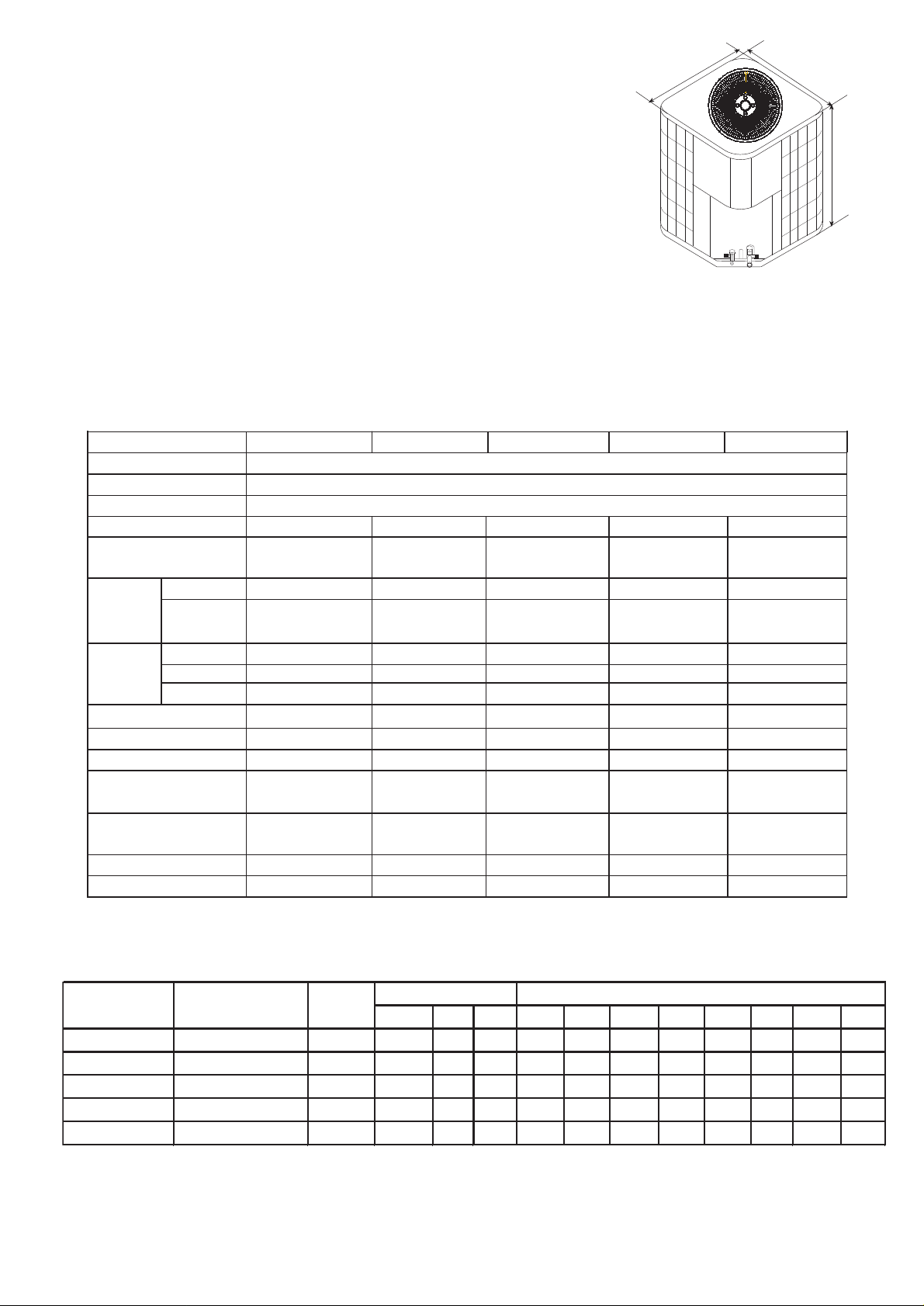
The dimensions for the condensing unit are illustrated in Figure 1. Physical and electrical
specifications are provided in Table 1 for 13 SEER systems respectively.
The Figure 2 show a schematic of the cooling only system.
Figure 1
D
W
H
Table 1:
MODEL: HC18D2VAR HC24D2VAR HC30D2VAR HC36D2VAR HC42D2VAR
Unit Supply Voltage
Normal Voltage Range
Compressor Brand
Minimum Circuit Amps
Max Fuse or Max CKT. BKR.
(HACR per NEC )
15 20 25 30 30
Rated Load Amps 5.4 8.0 10.1 11.8 13.2
Compressor Locked Running
Amps 36.0 53.5 61.0 78.0 78.0
Full Load Amps 0.86 0.86 1.4 1.6 1.6
Fan Motor Rated HP 1/8 1/8 1/4 1/3 1/3
Nominal RPM 1000 1000 1075 1120 1120
Liquid Line OD - In (mm) 3/8"[9.52] 3/8"[9.52] 3/8"[9.52] 3/8"[9.52] 3/8" [9.52]
Vapor Line OD - In (mm) 3/4"[19.05] 3/4"[19.05] 3/4"[19.05] 7/8"[22.2] 7/8"[22.2]
R-22 Charge -Oz (g) 84.81[2400] 84.81[2400] 123.67[3500] 137.81[3900] 141.34[4000]
Net Dimensions - In (mm) 21 1/2"*21 1/2"*23 3/8" 21 1/2"*21 1/2"*26 7/8" 24 1/4"*24 1/4"*23 3/8" 241/4"*24 1/4"*26 7/8" 24 1/4"*24 1/4"*30 3/8"
W*D*H
Shipping Dimensions - In (mm) 23" *23" *25 " 23"*23"*28 1/2" 26 7/8"*26 7/8"*25" 26 7/8"*26 7/8"*28 1/2" 26 7/8"*26 7/8"*32"
W*D*H
Net Weight - Lbs (kg) 143[65] 150[68] 176[80] 187[85] 198[90]
Approx Shipping Weight - Lbs (kg) 158[72] 165[75] 192[87] 202[92] 214[97]
Model:HC18-42D2VAR
7.6 10.9 14.0
[547* 547*595]
[585* 585*637]
[547* 547*683]
[585* 585*725]
208/230 60Hz 1PH
197 - 253
Bristol
[
[616* 616*595]
682* 682*637]
16.4
[616 *616*683] [616 *616*771]
[682*682*725] [682*682*813]
18.1
Table 2:System Cooling Capacity
2
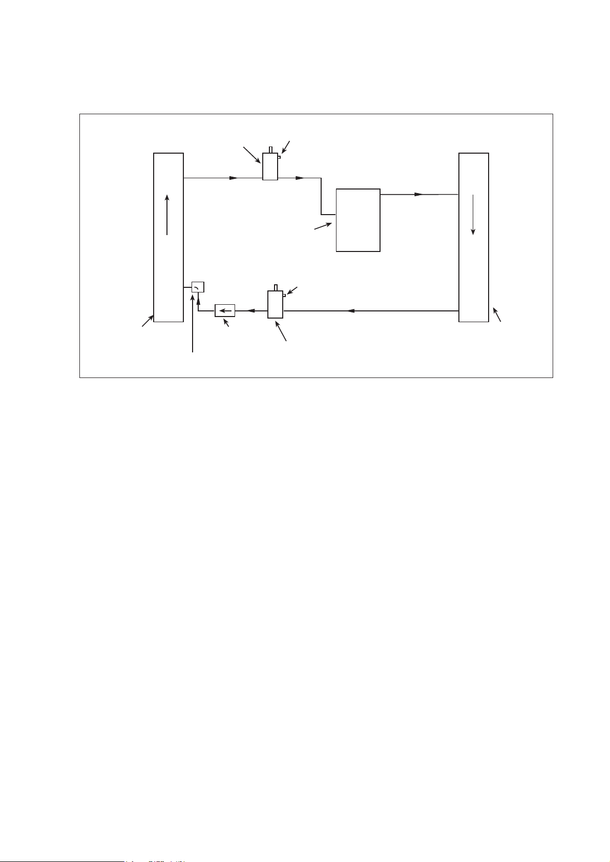
Figure 2
Central Air Conditioner Refrigerant Circuit
RVICE PORT
SERVICE VALVE
SE
COMPRESSOR
INDOOR COIL
R
O
T
A
ROPAV
E
DRIER(optional)
DISTRIBUTOR
SE
SE
RVICE VALVE
RVICE PORT
R
ES
NEDNOC
OUTDOOR COIL
!Warning - The drier is strongly recommended to be installed by installer and replaced once two
years. This will give your equipment great help in long life.
3

4.UNIT INSPECTION
This product has been inspected at the factory and released to the transportation agency without
known damage. Inspect exterior of carton for evidence of rough handling in shipment. Unpack
carefully. If damage is found, report immediately to the transportation agency.
5.EQUIPMENT PROTECTION FROM ENVIRONMENT
The metal parts of the unit may be subject to rust or corrosion in adverse environmental conditions.
This oxidation could shorten the unit life. Salt spray or mist in seacoast areas, sulphur or chlorine
from lawn watering systems and various chemical contaminants from industries such as paper mills
and petroleum refineries are especially corrosive.
If the unit is to be installed in an area where contaminants are likely to be a problem, special attention
should be given to the equipment location and exposure.
Avoid having lawn sprinkler heads spray directly on the unit cabinet.
In coastal areas, locate the unit on the side of the building away from the waterfront.
Shielding provided by fence or shrubs may give some protection.
Regular maintenance will reduce the buildup of contaminants and help to protect the unit's finish.
! WARNING - Disconnect all electrical power to the unit before servicing. Disconnect power to
both the indoor and outdoor units. NOTE: There may be more than one electrical disconnect switch.
Failure to shut off power can cause electrical shock resulting in personal injury or death.
Frequent washing of the cabinet, fan blade and coil with fresh water.
Regular cleaning and waxing of the cabinet with good automobile polish.
A good liquid cleaner may be used several times a year to remove matter that will not wash
off with water.
The best protection is frequent cleaning, maintenance and minimal exposure to contaminants.
6.INSTALLATION
6.1.GENERAL
These units are designed for outdoor installations. They can be mounted on a slab or rooftop. It
is important to consult your local code authorities at the time the first installation is made.
Check following points before attempting any installation:
Structural strength of supporting members.
Clearances and provision for servicing.
Power supply and wiring.
Location for minimum noise, where operating sounds will not disturb owner or neighbors.
Location where there is no risk of combustible gas leakage.
Location where external water drainage cannot collect around the unit.
Location where roof runoff water does not pour directly on the unit. Provide gutter or other
shielding at roof level. Don't locate unit in an area where excessive snow drifting may occur
or accumulate.
4