


No.0010572324
K
10 to 13 SEER 1.5 to 5 Tons
Models: HC18-60A1VAR/S
HC18-60C1VAR
HC18-60D1VAR
Installation & Operation Manual
Central Air Conditioner
The information contained in this booklet is subject to change without notice.

! WARNING
These instructions are intended as an aid to qualified, licensed service personnel for proper installation,
adjustment and operation of this unit. Read these instructions thoroughly before attempting installation
or operation. Failure to follow these instructions may result in improper installation, adjustment,
service or maintenance possibly resulting in fire, electrical shock, property damage, personal injury
or death.
This product is designed and manufactured to permit installation in accordance with National Codes. It
is the installer's responsibility to install the product in accordance with National Codes and/or
prevailing local codes and regulations. The manufacturer assumes no responsibility for equipment installed
in violation of any codes or regulations.
The United States Environmental Protection Agency (EPA) has issued various regulations r egarding
the introduction and disposal of refrigerants in this unit. Failure to follow these regulations may harm
the environment and can lead to the imposition of substantial fines. Because these regulations may vary
due to the passage of new laws we suggest that any work on this unit be done by a certified technician.
Should you have any questions please contact the local EPA office.
The manufacturer's warranty does not cover any damage or defect to the air conditioner caused by the
attachment or use of any components, accessories or devices (other than those authorized by the manufacturer)
into, onto, or in conjunction with the air conditioner. You should be aware that the use of unauthorized
components, accessories or devices may adversely affect the operation of the air conditioner and
may also endanger life and property. The manufacturer disclaims any responsibility for such loss or
injury resulting from the use of such unauthorized components, accessories or devices.
Attach the service panel to the outdoor unit securely. If the service panel is not attached securely, it
could result in a fire or an electric shock due to dust, water, etc.
Message to Owner
These instructions should be carefully read and kept near the product for future reference. While the instructions are
addressed primarily to the installer, useful maintenance information is included. Have your installer acquaint you with
the operating characteristics of the product and periodic maintenance requirements.
1
TABLE OF CONTENT
1.Introduction ---------------------------------------------------------------------------------------
2.Nomenclature for Model Number -------------------------------------------------------------
3.Specification -------------------------------------------------------------------------------------
4.Unit Inspection -----------------------------------------------------------------------------------
5.Equipment Protection From Environment ----------------------------------------------------
6.Installation ----------------------------------------------------------------------------------------
6.1. General ---------------------------------------------------------------------------------------
6.2.Unit clearances ------------------------------------------------------------------------------
6.3.Refrigerant piping ---------------------------------------------------------------------------
6.4.Electrical wiring -----------------------------------------------------------------------------
7.System Startup -----------------------------------------------------------------------------------
8.Operation ----------------------------------------------------------------------------------------
9.Miscellaneous -----------------------------------------------------------------------------------
9.1.Replacement parts --------------------------------------------------------------------------
9.2.Troubleshooting guide ---------------------------------------------------------------------
9.3.Wiring diagram -----------------------------------------------------------------------------
1.INTRODUCTION
This manual contains the installation and operating instructions for your new air conditioner.
Improper installation can result in unsatisfactory operation or dangerous conditions. Carefully
read this manual and any instructions packaged with separate equipment required to make up
the system prior to installation. Give this manual to the owner and explain its provisions. The
owner should retain this manual for future reference.
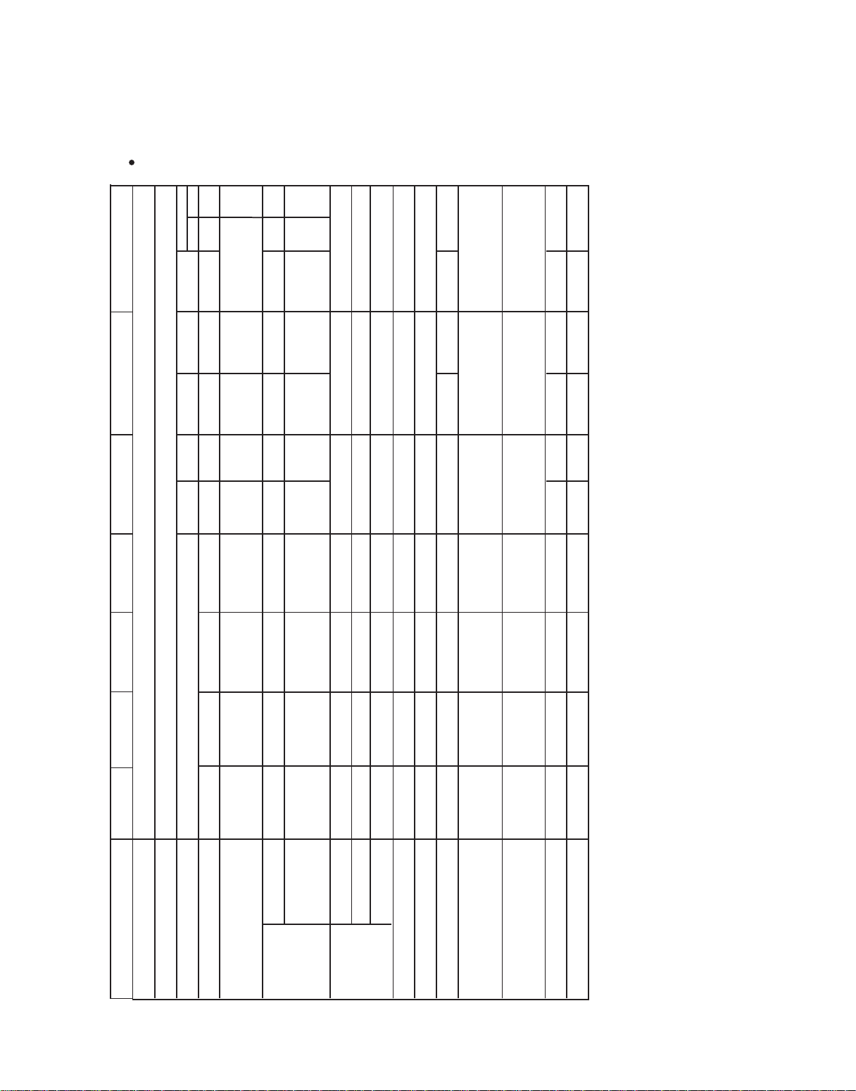
2.NOMENCLATURE FOR MODEL NUMBER
H Brand symbol - H: Haier
C System type - C: Air conditioner; R: Heat pump.
24 Nominal capacity in (000) Btuh
A SEER designation. A=10, B=11, C=12, D=13, E=14
1 Design series. 1 - 1st Generation
V Electric: V=208/230-1-60; C=208/230-3-60, D=460-3-60, Y=575-3-60
A Body style
R Compressor type
Example: HC24A1VAR
1
1
2
5
5
5
5
6
6
10
11
12
12
12
12
12
2
3.SPECIFICATION
The dimensions for the condensing unit are illustrated in Figure 1. Physical and electrical
specifications are provided in Table 1 for 10 SEER systems respectively.
Model:HC18-60A1VAR/S
40 35 45 50 60
18.3 15.8 21.3 24.4 26.9 28.9
130 90 130 140 149 165
1.43 1.43 1.43
1/3 1/3 1/3
1075 1075 1075
3/8" [9.52] 3/8"[9.52] 3/8"[9.52]
3/4"[19.05] 3/4"[19.05] 7/8"[22.2]
115.19[3260] 122.97[3480] 128.27[3630] 137.81[3900] 141.34[4000]
30 1/4*30 1/4*31 1/2 30 1/4*30 1/4*31 1/2 30 1/4*30 1/4*35 1/2
[770 *770*805] [ 770 *770*805] [ 770 *770*905]
32 3/4*32 3/4*36 32 3/4*32 3/4*36 32 3/4*32 3/4*40 1/2
[832*832*930] [ 832*832*930] [832*832*1030]
209[95] 198[90] 209[95] 200[91] 220[100] 216[98]
231[105] 222[101] 231[105] 222[101] 246[112] 242[110]
15 20 25 30
Rated Load Amps 7.4 9.6 11.8 14.4
Compressor Locked Running
Amps 48 60 73 88
Full Load Amps 0.86 0.86 1.4 1.4
Fan Motor Rated HP 1/8 1/8 1/5 1/5
Nominal RPM 850 1000 1075 1075
Liquid Line OD - In (mm) 3/8"[9.52] 3/8"[9.52] 3/8"[9.52] 3/8"[9.52]
Vapor Line OD - In (mm) 5/8"[15.88] 5/8"[15.88] 3/4"[19.05] 3/4"[19.05]
R-22 Charge -Oz (g) 49.47[1400] 63.60[1800] 88.34[2500] 93.64[2650]
Net Dimensions - In (mm) 23*23*24 23*23*24 23*23*31 1/2 23*23*31 1/2
W*D*H [585 *585*605] [585 *585*605] [ 585 *585*805] [ 585 *585*805]
Shipping Dimensions - In (mm) 25*25*28 1/4 25*25*28 1/4 25*25*36 25*25*36
W*D*H [632*632*719] [632*632*719] [632* 632*919] [632* 632*919]
Net Weight - Lbs (kg) 123[56] 125[57] 134[61] 141[64]
Approx Shipping Weight - Lbs (kg) 141[64] 143 [65] 158[72] 165[75]
Bristol
H20R
H29A
22.6
147
50
Table 1:
HC60A1VARHC48A1VARHC42A1VARHC36A1VASHC30A1VARHC24A1VARHC18A1VAR
MODEL:
Unit Supply Voltage
Normal Voltage Range
Compressor Brand
Minimum Circuit Amps
208/230-1-60
197 - 253
Bristol
Sanyo Bristol Sanyo Bristol Sanyo
10.1
12.9 16.2 19.4 24.3 21.2 28.1 31.9 35.1 37.6 29.7
Max Fuse or Max CKT. BKR.
(HACR per NEC )
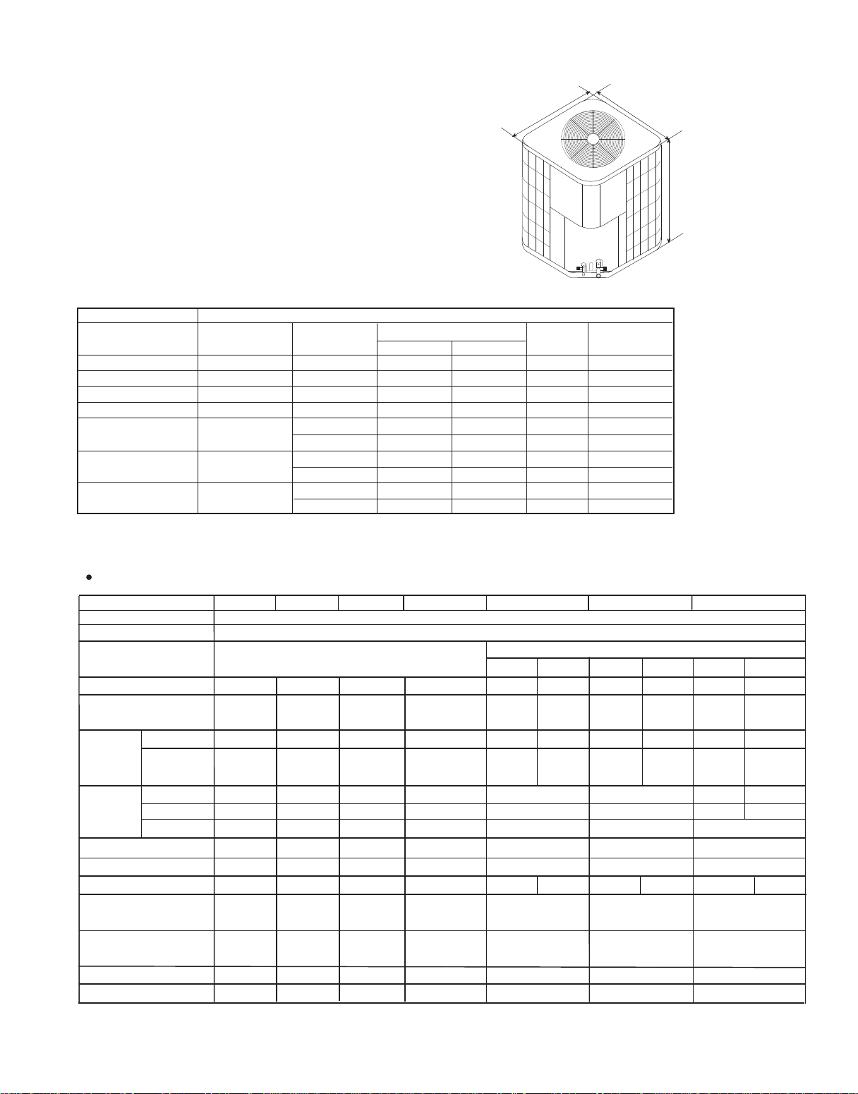
Figure 1
Minimum Circuit Amps
15 25 25 30 40 35 40 60 60
Rated Load Amps 7.4 9.6 11.8 13.0 16.7 15.8 18.7 26.6 28.9
Compressor Locked Running
Amps 48 60 73 85 105 90 135 155 165
Full Load Amps 0.86 1.4 1.4 1.43 1.43 1.43 1.43
Fan Motor Rated HP 1/8 1/5 1/5 1/3 1/3 1/3 1/3
Nominal RPM 850 1075 1075 1075 1075 1075 1075
Liquid Line OD - In (mm) 3/8"[9.52] 3/8"[9.52] 3/8"[9.52] 3/8"[9.52] 3/8" [9.52] 3/8"[9.52] 3/8"[9.52]
Vapor Line OD - In (mm) 5/8"[15.88] 3/4"[19.05] 3/4"[19.05] 3/4"[19.05] 7/8"[22.2] 7/8"[22.2] 7/8"[22.2]
R-22 Charge -Oz (g) 74.2 [2100] 91.87[2600] 88.34[2500] 102.47[2900] 132.51[3750] 125.44[3550]
Net Dimensions - In (mm) 23*23*27 3/4 23*23*27 3/4 23*23*31 1/2 30 1/4*30 1/4*27 3/4 30 1/4*30 1/4*35 1/2 301/4*30 1/4*35 1/2 30 1/4*30 1/4*31 1/2
W*D*H [585* 585*705] [585* 585*705] [585* 585*805] [770 *770*705] [770 *770*905] [770 *770*905] [ 770 *770*805]
Shipping Dimensions - In (mm) 25*25*32 1/4 25*25*32 1/4 25*25*36 32 3/4*32 3/4*32 1/2 32 3/4*32 3/4*40 1/2 32 3/4*32 3/4*40 1/2 32 3/4*32 3/4*36
W*D*H [632* 632*819] [632* 632*819] [632* 632*919] [832*832*830] [832*832*1030] [832*832*1030] [832* 832*930]
Net Weight - Lbs (kg) 123[56] 125[57] 139[63] 196[89] 231[105] 238[108] 298[135]
Approx Shipping Weight - Lbs (kg) 141[64] 143[65] 152[69] 222[101] 257 [117] 264[120] 321[146]
183.75[5200]
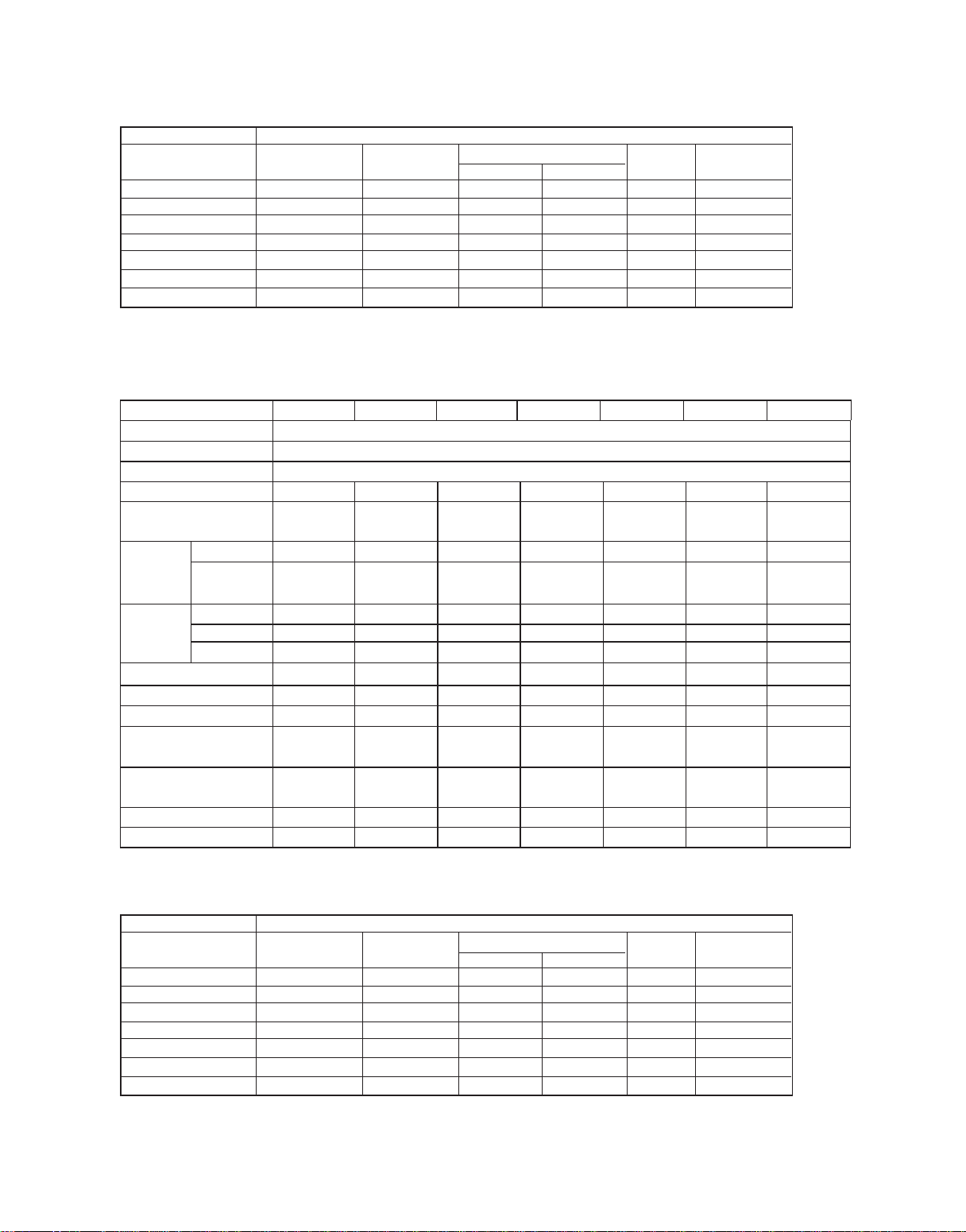
The dimensions for the condensing unit are illustrated in Figure 1. Physical and electrical
specifications are provided in Table 3 for 12 SEER systems respectively.
3
H
W
D
Table 2:System Cooling Capacity
Outdoor Unit With This Indoor Air handler
Model Number
HC18A1VAR HB2400VA1M20
HC24A1VAR HB2400VA1M20
HC30A1VAR HB3000VA1M20
HC36A1VAS HB3600VA1M20
HC42A1VAR HB4200VA1M25
HC48A1VAR HB4800VA1M25
HC60A1VAR HB6000VA1M25
Air Handler
Cooling Capacity (Btu/h) SEER Rated
Sensible Total CFM(Outdoor)
13000
17000
20000
24000
1850
1850
1950
1950
18000
24000
28000
34000
10
10
10
10
28400
29160
33120
2700
2700
2900
40000
40500
46000
10
10
10
33120
40170
40180
2900
2900
2900
46000
55800
56000
10
10
10
Compressor
brand
Bristol
Bristol
Bristol
Bristol
Bristol
Bristol
Bristol
Sanyo
Sanyo
Sanyo
H23R
H20R
H29A H23R
H29A
H20J
28.8
145
2.5
60
1/2
171.38[4850]
120.14[3400] 127.21[3600]
Model:HC18-60C1VAR
Table 3:
MODEL: HC18C1VAR HC24C1VAR HC30C1VAR HC36C1VAR HC42C1VAR HC48C1VAR HC60C1VAR
Unit Supply Voltage
Normal Voltage Range
208/230-1-60
197 - 253
Compressor Brand
Bristol
Bristol
10.1 13.4 16.2 17.7 22.3 21.2
34.724.8 37.6 38.5
Max Fuse or Max CKT. BKR.
(HACR per NEC )
4
Outdoor Unit With This Indoor Air handler
Model Number
HC18C1VAR HB2400VC1M20
HC24C1VAR HB2400VC1M20
HC30C1VAR HB3600VA1M20
HC36C1VAR HB3600VC1M25
HC42C1VAR HB4800VA1M25
HC48C1VAR HB4800VA1M25
HC60C1VAR HB6000VC1M25
41800
2900
58000
12
Bristol
Table 4:System Cooling Capacity
Air Handler
Cooling Capacity (Btu/h) SEER Rated
Sensible Total CFM(Outdoor)
14820
18720
23400
25920
1950
1950
1950
2700
19000
24000
30000
36000
12
12
12
12
30240
34560
2900
2900
42000
48000
12
12
Compressor
brand
Bristol
Bristol
Bristol
Bristol
Bristol
Bristol
15 20 20 25 30 35 55
Rated Load Amps 6.2 8.6 9.2 11.7 13.0 15.8 25.0
Compressor Locked Running
Amps 41 60 60 73 85 90 150
Full Load Amps 0.86 0.86 0.86 1.3 1.43 2.0 2.0
Fan Motor Rated HP 1/8 1/6 1/6 1/4 1/3 1/3 1/3
Nominal RPM 1000 840 840 850 1075 960 880
Liquid Line OD - In (mm) 3/8"[9.52] 3/8"[9.52] 3/8"[9.52] 3/8"[9.52] 3/8" [9.52] 3/8"[9.52] 3/8"[9.52]
Vapor Line OD - In (mm) 3/4"[19.05] 3/4"[19.05] 3/4"[19.05] 7/8"[22.2] 7/8"[22.2] 7/8"[22.2] 7/8"[22.2]
R-22 Charge -Oz (g) 93.64[2650] 102.47[2900] 121.91[3450] 134.28[3800] 148.41[4200] 178.45[5050] 196.11[5550]
Net Dimensions - In (mm) 23*23*31 1/2 30 1/4*30 1/4*27 3/4 30 1/4*30 1/4*31 1/2 30 1/4*30 1/4*31 1/2 30 1/4*30 1/4*35 1/2 30 1/4*30 1/4*31 1/2 30 1/4*30 1/4*35 1/2
W*D*H
[585* 585*805]
[770* 770*705]
[770* 770*805]
[770 *770*805] [770 *770*905] [770 *770*805] [ 770 *770*905]
Shipping Dimensions - In (mm) 24 3/4*24 3/4*36 32 3/4*32 3/4*32 1/2 32 3/4*32 3/4*36 32 3/4*32 3/4*36 32 3/4*32 3/4*40 1/2 32 3/4*32 3/4*36 32 3/4*32 3/4*40 1/2
W*D*H
[632* 632*919]
[832* 832*830]
[
832* 832*930]
[832*832*930] [832*832*1030] [832*832*930] [832*832*1030]
Net Weight - Lbs (kg) 156[71] 194[88] 198[90] 203[92] 231[105] 244[111] 258[117]
Approx Shipping Weight - Lbs (kg) 167[76] 209[95] 216[98] 220[100] 249 [113] 262[119] 282[128]
The dimensions for the condensing unit are illustrated in Figure 1. Physical and electrical
specifications are provided in Table 5 for 13 SEER systems respectively.
Model:HC18-60D1VAR
Outdoor Unit With This Indoor Air handler
Model Number
HC18D1VAR HB2400VD1M20
HC24D1VAR HB2400VD1M20
HC30D1VAR HB3600VD1M22
HC36D1VAR HB3600VD1M22
HC42D1VAR HB4800VD1M22
HC48D1VAR HB4800VD1M22
HC60D1VAR HB6000VD1M22
40700
4000
55000
13
Bristol
Table 6:System Cooling Capacity
Air Handler
Cooling Capacity (Btu/h) SEER Rated
Sensible Total CFM(Outdoor)
13300
17700
20669
25900
1350.0
1800.0
2100
2700
18000
24000
28000
35000
13
13
13
13
29600
34800
3200
3600
40000
47000
13
13
Compressor
brand
Bristol
Bristol
Bristol
Bristol
Bristol
Bristol
Table 5:
MODEL: HC18D1VAR HC24D1VAR HC30D1VAR HC36D1VAR HC42D1VAR HC48D1VAR HC60D1VAR
Unit Supply Voltage
Normal Voltage Range
Compressor Brand
Minimum Circuit Amps
208/230-1-60
197 - 253
Bristol
8.6 11.6 12.4 15.9
17.7 21.8 33.3
Max Fuse or Max CKT. BKR.
(HACR per NEC )
 Loading...