

Haier HBU-18CA03T3, HBU-24CA03T3, HBU-36CA03T3, HBU-42CA03T3, HBU-50CA03T3 Operation & Installation Manual
...
HBU-18CA03T3
HBU-24CA03T3
HBU-36CA03T3
HBU-42CA03T3
HBU-50CA03T3
HBU-60CA03T3
Operation & Installation Manual
CASSETTE TYPE AIR CONDITIONER
Indoor Unit
No. 0150504303
B
Before using the air conditioner, please read this manual carefully.
Please keep this manual properly for future use.
Contents
Cautions
.....................................................................................................
Introduction to Spare Parts
............................................................................
Maintenance
.............................................................................................
Trouble Shooting
...................................................................................
When Trouble Happens
.........................................................................
Customer Need-to-know
..............................................................................
Precaution for Installation
...........................................................................
Installation Tools
..........................................................................................
Installation Procedure
..............................................................................
Name of Parts
..............................................................................................
Safety Cautions .......................................................................................
Installation Procedure
.............................................................................
1-5
6
7-10
11-12
13-14
15
16
17
18-29
30
31-32
33-42
outdoor unit
indoor unit
Cautions
1
Disposal of the old air conditioner
Before disposing an old air conditioner
that goes out of use, please make sure it's
inoperative and safe. Unplug the air
conditioner in order to avoid the risk of
child entrapment.
It must be noticed that air conditioner
system contains refrigerants, which require
specialized waste disposal. The valuable
materials contained in a air conditioner can
be recycled. Contact your local waste
disposal center for proper disposal of an
old air conditioner and contact your local
authority or your dealer if you have any
question. Please ensure that the pipework
of your air conditioner does not get
damaged prior to being picked up by the
relevant waste disposal center, and
contribute to environmental awareness by
insisting on an appropriate, anti-pollution
method of disposal.
Disposal of the packaging of your new
air conditioner
All the packaging materials employed in
the package of your new air conditioner
may be disposed without any danger to the
environment.
The cardboard box may be broken or cut
into smaller pieces and given to a waste
paper disposal service. The wrapping bag
made of polyethylene and the polyethylene
foam pads contain no fluorochloric
hydrocarbon.
Consult your local authorities for the name and
address of the waste materials collecting
centers and waste paper disposal services
nearest to your house.
Safety Instructions and Warnings
Before starting the air conditioner, read the
information given in the User's Guide
carefully. The User's Guide contains very
important observations relating to the
assembly, operation and maintenance of the
air conditioner.
The manufacturer does not accept
responsibility for any damages that may
arise due to non-observation of the following
instruction.
Damaged air conditioners are not to be
put into operation. In case of doubt, consult
your supplier.
Use of the air conditioner is to be carried
out in strict compliance with the relative
instructions set forth in the User's Guide.
Installation shall be done by professional
people, don't install unit by yourself.
All these valuable materials may be taken to
a waste collecting center and used again after
adequate recycling.
For the purpose of safety, the air
conditioner must be properly grounded in
accordance with specifications.
Always remember to unplug the air
conditioner before opening inlet grill. Never
unplug your air conditioner by pulling on the
power cord. Always grip plug firmly and
pull straight out from the outlet.
3. The wiring method should be in line with the
local wiring standard.
4. The power cable and connecting cable are
self-provided. The requirement of the power
cable:
All the cables shall have got the European
authentication certificate.
5. The breaker of the air conditioner should be
all-pole switch; and the distance between its two
contacts should be no less 3mm. Such means for
disconnection must be incorporation in the fixed
wiring.
6. The waste battery shall be disposed properly.
7. The indoor unit installation height is at least
2.5m.
All electrical repairs must be carried out
by qualified electricians. Inadequate repairs
may result in a major source of danger for
the user of the air conditoiner.
Do not damage any parts of the air
conditioner that carry refrigerant by
piercing or perforating the air conditioner's
tubes with sharp or pointed items, crushing
or twisting any tubes, or scraping the
coatings off the surfaces. If the refrigerant
spurts out and gets into eyes, it may result
in serious eye injuries.
Do not obstruct or cover the ventilation
grille of the air conditioner. Do not put
fingers or any other things into the
inlet/outlet and swing louver.
Do not allow children to play with the air
conditioner. In no case should children be
allowed to sit on the outdoor unit.
Specifications
The refrigerating circuit is leak-proof.
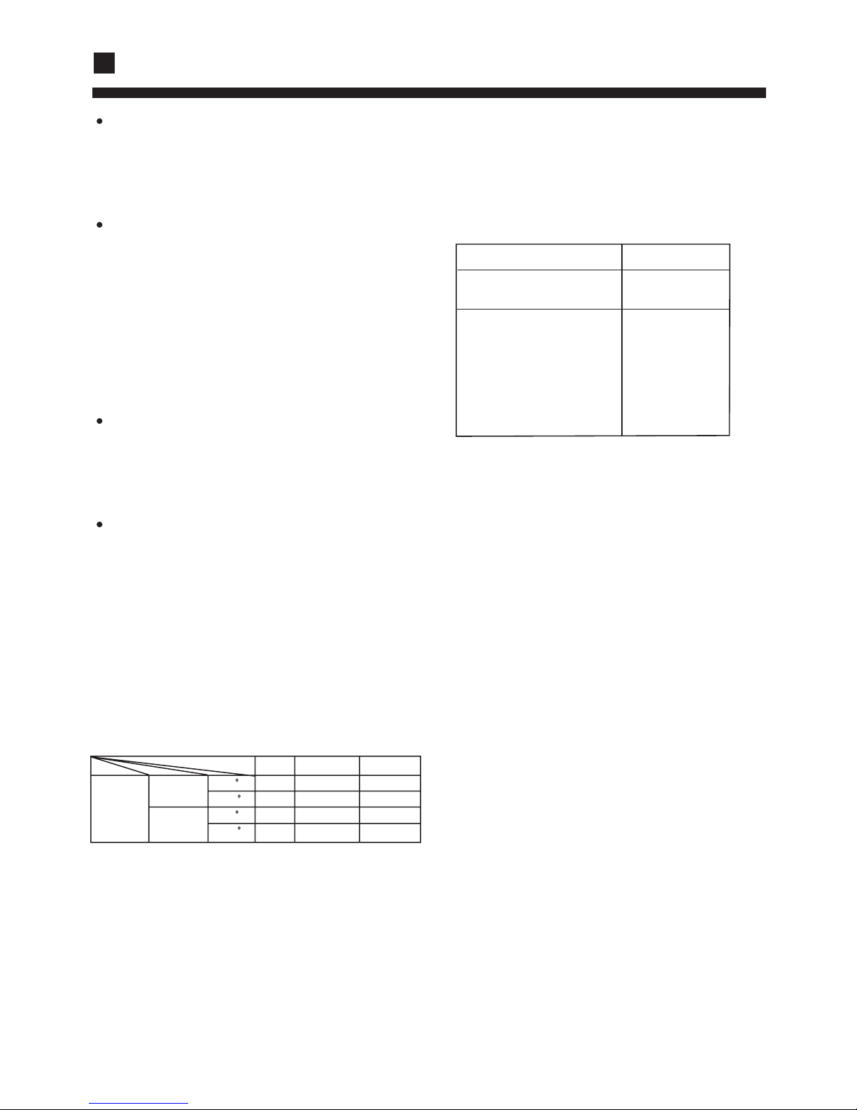
1. Applicable ambient temperature range:
The machine is adaptive in following
situation
Model
2. If the supply cord is damaged, it must be
replaced by the manufacturer or its service
agentor a similar qualified person.
Cooling
Indoor
outdoor
Rated Maximum Minimum
29 32 21
19 23 15
46 52 21
24 31 -
DB C
WB C
DB C
WB C
Cautions
Power Cable
5G 4.0mm
2
5G 2.5mm
2
2
HBU-24CA03T3
HBU-36CA03T3
HBU-42CA03T3
HBU-50CA03T3
HBU-60CA03T3
HBU-18CA03T3
WARNING!
Carefully read the following information in order to operate the airconditioner correctly.
Below are listed three kinds of Safety Cautions and Suggestions.
WARNING!
CAUTION!
Incorrect operations may result in injuries or machine damages; in some cases may
cause serious consequences.
Incorrect operations may result in severe consequences of death or serious injuries.
INSTRUCTIONS: These information can ensure the correct operation of the machine.
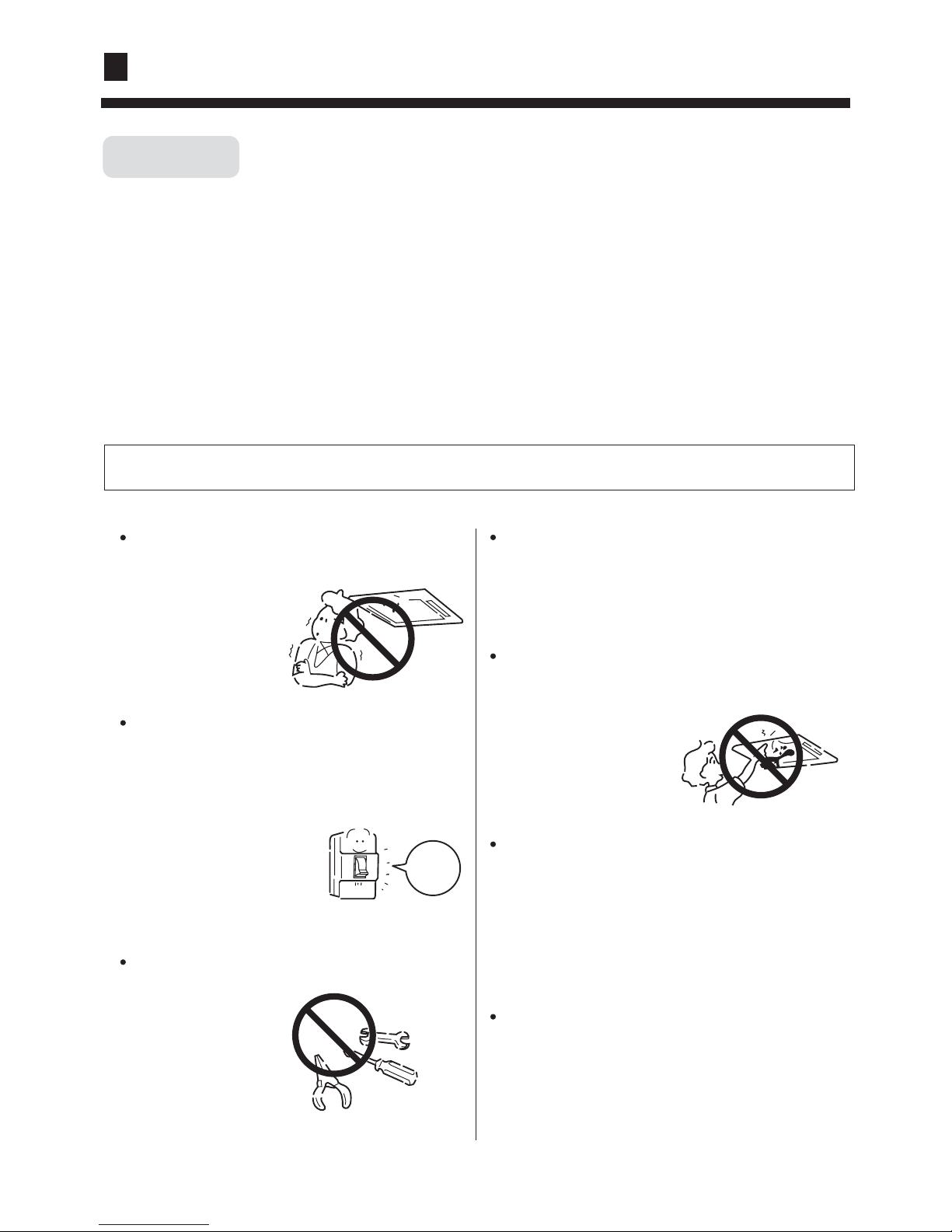
Be sure to conform with the following important Safety Cautions.
The Safety Cautions should be at hand so that they can be checked at any time when needed.
If the conditioner is transferred to the new user, this manual should be as well transferred to the new user.
Otherwise the one
will feel unpleasant
or harm ones' health.
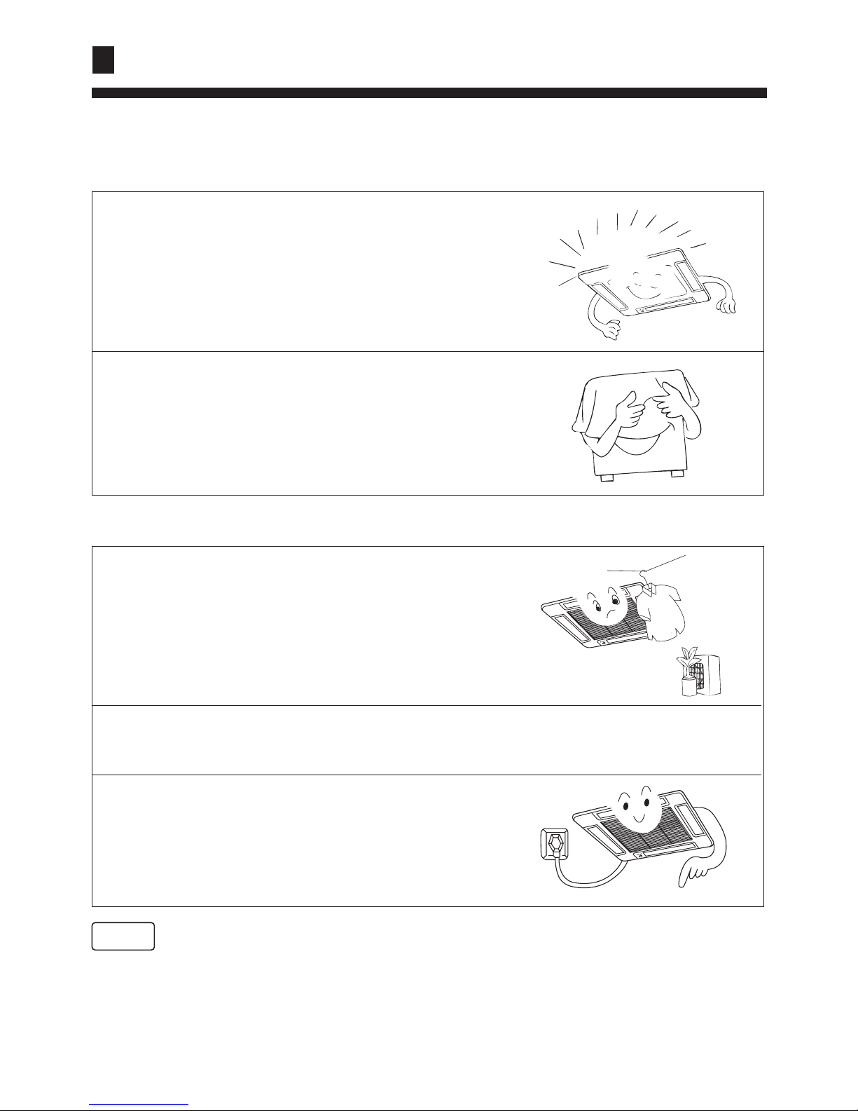
If any abnormal phenomena is found (e. g.
smell of firing), please cut off the power
supply immediately, and contact the dealer
to find out the handling method.
In such case, to continue
using the conditioner will
damage the conditioner,
and may cause electrical
shock or fire hazard.
When need maintenance and repairment,
call dealer to handle it.
Incorrect mainten-
ance and repairment
may cause water
leak, electrical shock
and fire hazard.
switch
off
Please let the dealer be responsible for installing
the conditioner.
Incorrect installation may cause water leak, elec-
trical shock and fire hazard.
Don't put fingers or any other things into the
inlet/outlet and swing louver while the condi-
tioner is in operation.
Because the highspeed
fan is very dangerous
and may cause injuries.
Call the dealer to take measures to prevent the
refrigerant from leaking.
If conditioner is installed in a small room be sure
to take every measure in order to prevent suffoca-
tion accident even in case of refrigerant leakage.
When conditioner is deinstalled or reinstalled
dealer should be responsible for them.
Incorrect installation may cause water leaking,
electrical shock and fire hazard.
Don't blow the human body with the cooling
air too long, and don't let the room tempera-
ture decrease too low
either.
Safety cautions
Cautions
3
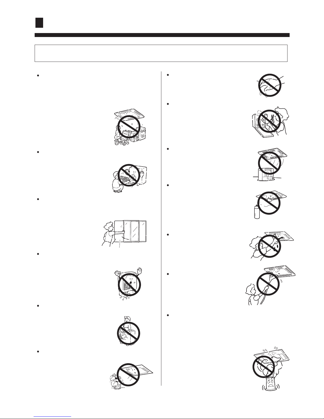
CAUTIONS!
Conditioner should not be used for any other
purpose other than airconditioning.
Don't use air-conditioner for any other special
purposes, e.g. the preservation and protection
of food, animals, plants,
pecision apparatus as well
as work of art, otherwise
the qualities of these
stuffs may be damaged.
Don't dismantle the outlet of the outdoor unit.
The exposure of fan is
very dangerous which
may harm human beings.
When air-conditioner is co-used with other
heat-radiator the frequent replacement of
room atmosphere should be required.
Inefficient ventilation may cause
suffocation.
After a long time use of air-conditioner the
base should be checked for any damages.
If the damaged base is
not repaired, the unit
may fall down and
cause accidents.
No goods or nobody is permitted to placed on
or stand on outdoor unit.
The falling of goods and
people may cause accidents.
Pets and plants should not be blowed directly
in the air flow.
Otherwise will suffer
damage.
Don't operate the air-conditioner with damp hands.
Otherwise will be shocked.
Only use correctly-typed fuse.
May not use wire or any other
materials replacing fuse, otherwise may cause faults or fire
accidents.
Don't place any burning unit
in the air flow of air-conditioner,
which may cause incomplete
combustion.
No inflammable spray fluid
should be permitted to be
placed or used near to airconditioner otherwise may
cause fire accidents.
Air-conditioner should be
cleaned only after power
supply is cut off to keep
from shock or hurt.
Don't clean air-conditioner
with water.
Otherwise may cause
shock.
Otherwise the poisonous chemicals may settle
in air-conditioner which harm the health of
chemical-allergic people.
When use the fumigating insecticide don't
open air-conditioner.
Cautions
4
WARNING !
CAUTION !
Please ask the dealer or specialist to install, never try by the users themselves. After the installation
please be sure of the following conditions.
Incorrect installation may cause water leaking, shock and fire hazard.
Please call dealer to install the air-conditioner.
Air-conditioner can't be installed in the environment with inflammable gases because the
inflammable gases near to air-conditioner may
cause fire hazard.
Installed electrical-leaking circuit breaker.
Connect earthing wire.
Use discharge pipe correctly to ensure efficient
discharge.
[Location]
[Wiring]
[Operating noise]
It easily cause electrical shock without circuit
breaker.
Air-conditioner should be located in well-vented
and easily-accessible place.
Air-conditioner should not be located in the
following places:
(a) Places with machine oils or other oil vapours.
(b) Seaside with high salt content in the air.
(c) Near to hot spring with high content of sulfide
gases.
(d) Area with frequent fluctuation of voltage e.g.
factory, etc.
(e) In vehicles or ships.
(f) Kitchen with heavy oil vapour or humidity.
(g) Near to the machine emitting electric-magnetic
waves.
(h) Places with acid, alkali vapuor.
TV, radio, acoustic appliances etc are at least 1 m
far away to the indoor unit, outdoor unit, power
supply wire, connecting wire, pipes, otherwise
images may be disturbed or noises be created.
Earthing wire should not be connected to the gas pipe, water pipe,
lightning rod or phone line, incorrect earthing may cause shock.
Incorrect pipe use may cause water leaking.
As required, take measures against heavy snow.
Air-conditioner should be equipped with special
power supply wire.
Chose the following locations:
(a) Capable of supporting air-conditioner weight,
don't increase operating noise and vibration.
(b) Hot vapour from outdoor unit outlet and ope rating noise don't disturb neighbour.
No obstacles around the outdoor unit outlet.
Earthing
Installation
Cautions
5
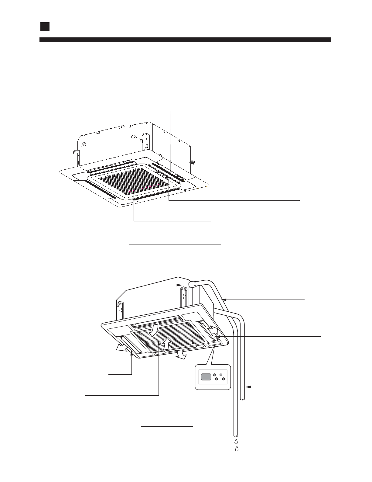
Introduction to Spare Parts
6
Swing louver
(Air flow direction can be adjusted by using
the SWING button on the remote controller)
Air Inlet Grille
Air Filter
(Inside of the Inlet Grille)
Operating Control Panel
Indoor unit
Drain Hose
Swing fender
Refrigerant pipe
Cable line
Earthing line
Air filter
Outlet
Suction grill
(located in the suction grill)
In cooling operation,
to discharge the
water from inside the
room.
Discharge unit (built in)
(located in the outlet)
HBU-18CA03T3
HBU-24CA03T3
HBU-36CA03T3
HBU-42CA03T3
HBU-50CA03T3
HBU-60CA03T3
.
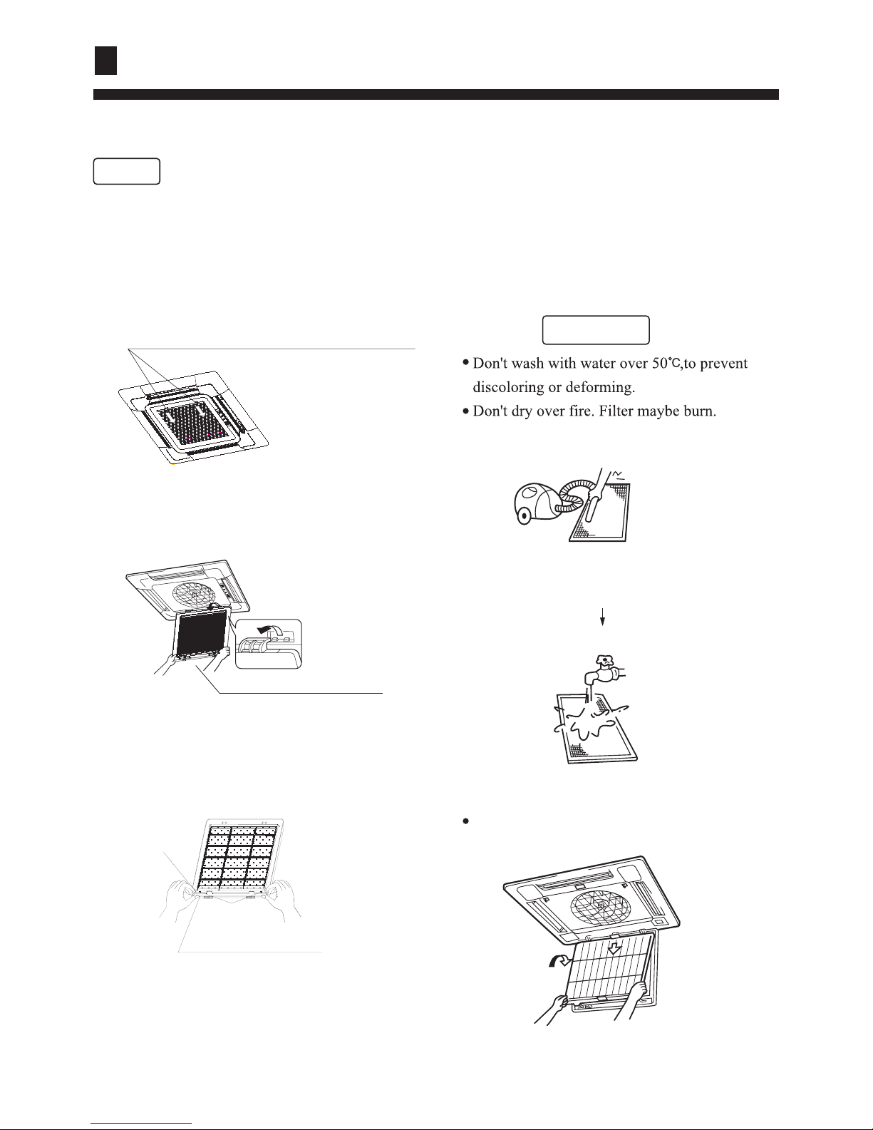
Maintenance
[Clean air filter]
NOTE
1. Open inlet grill
When having to clean, don't dismantle air-filter,otherwise may cause faults.
In the environment where there is too much dust, air filter should be cleaned for more times.
(about half a year one time)
(B) Wash with water.
With too much dust, use soft brush and neutral
detergent.
Swing off the water, and then place in cool place.
Pull the two handles at the same
time, slowly draw them out.
¢
¢
2. Dismantle air filter
clip cpening
bottom of filter
frame of air inlet grill
¢
CAUTION!
3. Clean
(A) Remove dust with vacuum filter.
¢
¢
4. Install air filter
Put filter into protruding parts at the top of the
inlet grill.
¢
7
remove the air inlet grill
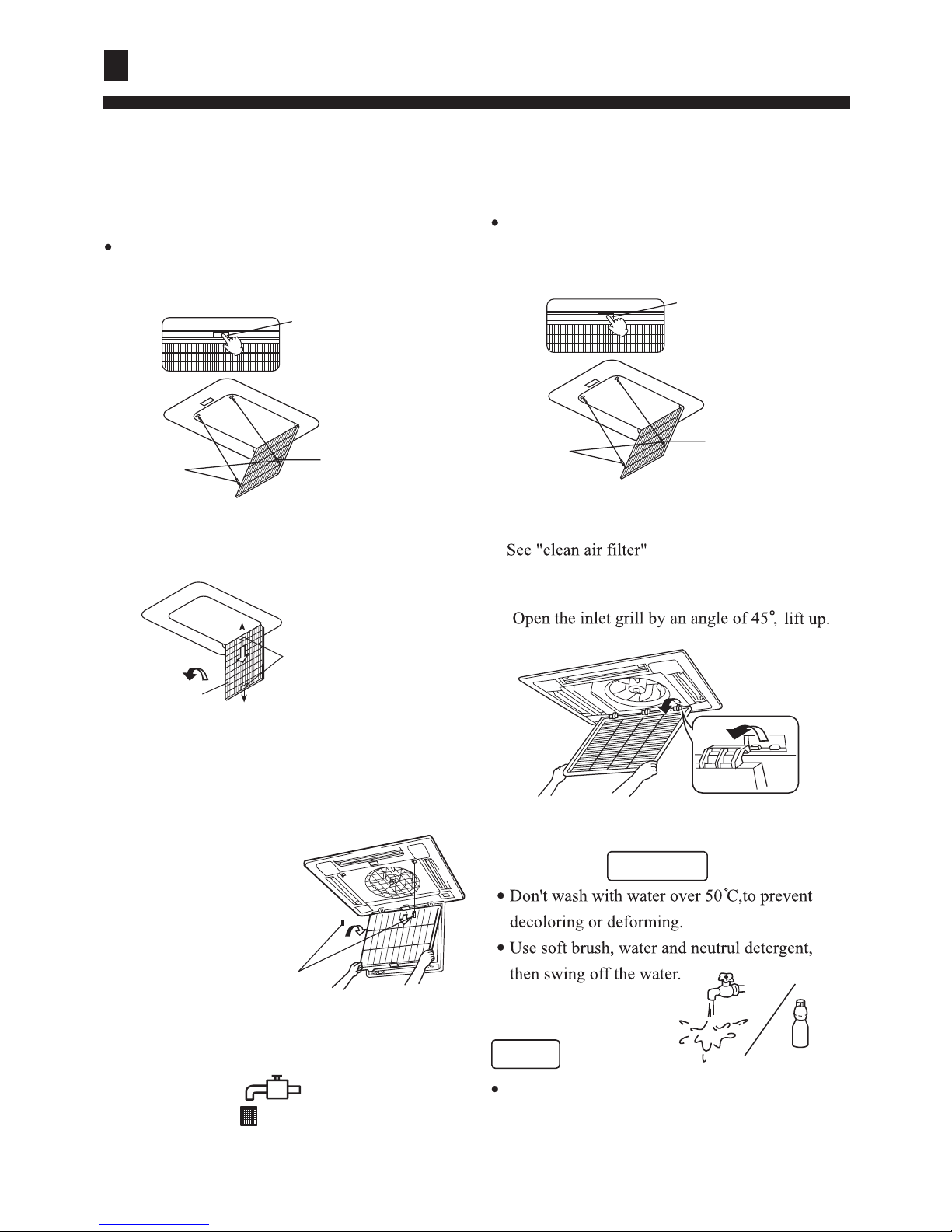
5. Close inlet grill
the reverse sequance of 1.
8. Dismantle air filter
9. Install air filter
(1) Put filter into protruding parts at the top ofthe
inlet grill.
(2) Connect the two pothooks with inlet grill. See 7.
Connet the two pothooks
with inlet grill
[Clean inlet grill]
1. Open inlet grill
10. Close inlet grill
11. Press the filter signal return key on the
controller.
See 6.
'' ''
Maintenance
6. Open inlet grill
Press the elliptical "PUSH" knob, the inlet grill will
automatically drop. (the inlet grill is catched with
two pothooks)
PUSH
Press the elliptical knob
the inlet grill will
automatically drop
Open two
pothooks
Pothook
3. Take of inlet grill
4. Clean
CAUTION!
NOTE
When the filter too much dust
To spray the special detergent for vent fan or
utensils.
2. Take off airfilter
7.Open two pothooks
8
Press the elliptical "PUSH" knob, the inlet grill
will automatically drop. (the inlet grill is catched
with two pothooks)
PUSH
Press the elliptical knob
the inlet grill will
automatically drop
Open two
pothooks
Pothook
Drag the knob of
the grill back lift
the filter and take
down.
Air filter
[Clean outlet and shell]
CAUTION!
Don't use gasoline, benzene, dilutant, polishing
powder, or liquid inseticide.
5. Install inlet grill
6. Install air filter
7. Close inlet grill
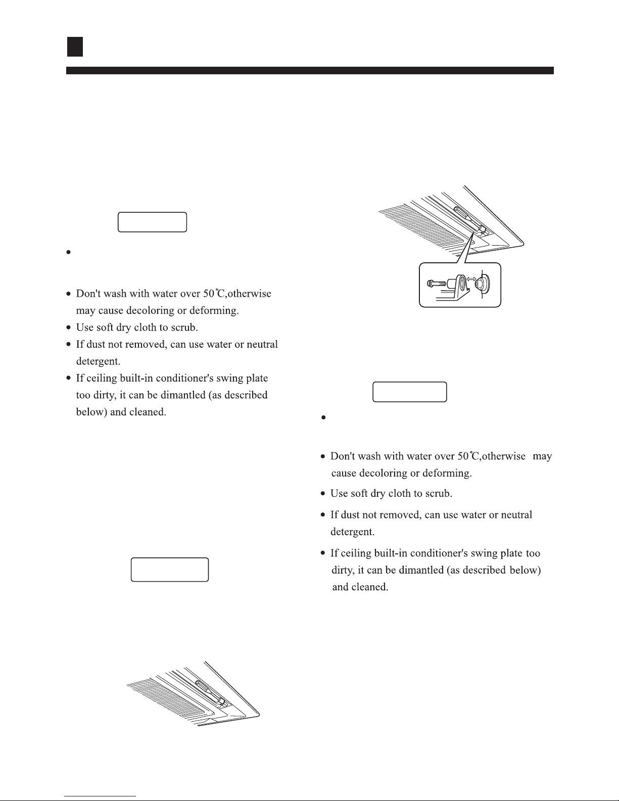
[Clean outlet and shell]
see 3
see "Clean air filter"
see 1
CAUTION!
Don't use gasoline, benzene, dilutant,
polishing powder, or liquid inseticide.
[Dismantle and install swing plate ]
1. Fix the swing plate at the bottom.
2. Dismantle the swing plate.
CAUTION!
Use water to clean the plate and don't heavily
scrub, otherwise the fine hair may fall off.
Unscrew the screw at both ends of the swing
plate.
[Dismantle and install swing plate ]
3. Install swing plate
Lightly rotate swing plate to insert the ridge
at both ends of the outlet into the groove
and then screw up.
Maintenance
9
NOTE
1. The inner part of indoor unit must be cleaned. Consult dealer, because clean must be done by
technician.
2. In cooling operation, discharging system discharge water in room.
Seasonal Reserve
Operate the unit with FAN mode on a fair day for about half
a day to dry the inside of the unit well.
Stop operation and turn off the power supply switch .Electric
power is consumed even the air conditioner is in stop.
Clean the air filter, indoor unit and outdoor unit,and cover
the unit with dustcoat.
Pre-season Care
See that there is no obstacles blocking the air
inlet and air outlet of both indoor and outdoor
unit to avoid reduce the working efficiency.
Be sure to install the air filter, ensure that the air filter is not dirty. Otherwise may result in
machine damages or cause malfunciton due th dust inside the unit
To prevent compressor when start in HEAT mode,
please cut in the power supply switch 12 hours
before starting run,furthermore, always keep the
power supply switch on during the using senson.
Post-season Care
Maintenance
10

The followings are not malfunction
Hua
Hua
Water flowing sound is heard When the air conditoner is started, when the
compressor starts or stops during operation
or when the air conditioner is stopped,it sometimes sounds "Bi- Bi-"or "Godo-Godo". It is
the flowing sound of the refrigerant , not a
malfunction.
Cracking sound is heard
It smells.
This is caused by heat expansion or contraction
of plastics.
Air blown out from the indoor unit sometimes
smells. The smell results from smells of
furniture, paint , tobacco absorbed by indoor
unit.
During operation, white fog comes out of
indoor unit.
When in COOL or DRY mode, a thin water
fog can be seen blown out of unit ,this is the
condensed fog because the suddenly cooled
indoor air is blown out.
Automatically switch into FAN mode during
cooling.
To prevent frost from being accumulated on the
indoor unit heat exchanger, it sometimes automatically switched into the FAN mode,but it will
soon back to the cooling mode.
The air conditioner cannot be restarted soon
after it stops.
Air conditioner does not start?
This is because of the self-protection function
of the system, therefore,it cannot be restarted
for about three minutes after it stops.
Please wait for
three minutes
11
Trouble Shooting
Trouble Shooting
**?
ON
OFF
Air does not blow or the fan speed cannot be
changed during drying.
In DRY mode, when room temperature
becomes 2 ¡ higher than temperature setting,
unit rill run intermittently at LO speed regardless
of FAN setting
During heating,indoor fan is still running even
unit is stopped.
To get ride of the excess heat, indoor fan will
continue running for a while after unit automatically stops.
Water or vapor generated from the outdoor
unit during heating.
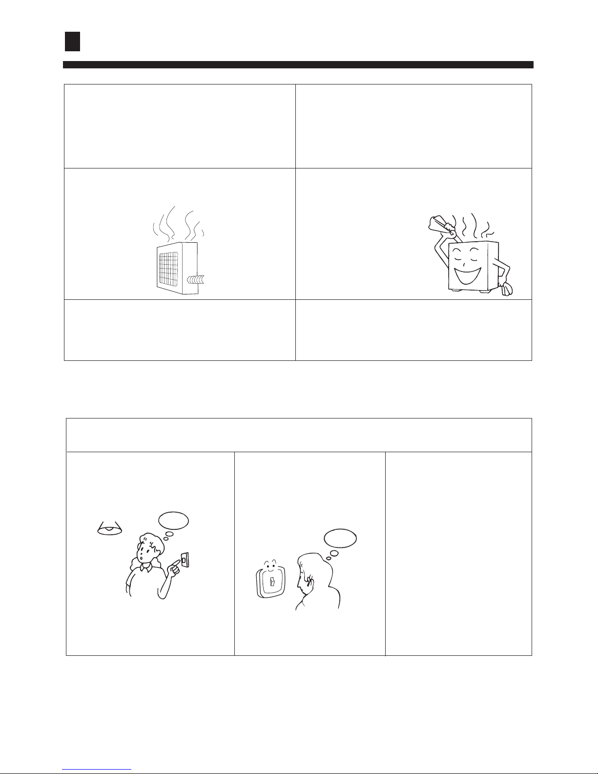
Please check the following things about your air conditioner before making a
service call.
Unit fails to start.
Is the power supply switch on ?
Power supply switch is not in
ON position.
Is city supply power normal ?
Is the earth leakage breaker
in action ?
Be sure to turn off the power
supply switch immediately and
contact the sales dealer.
This happens when the frost accumulated on
the outdoor unit is removed (during defrosting
operation).
Defrosting operation
12

When Trouble Happens
Insufficient cooling or heating
The operation controller
adjusted as required
Air filter too dirty ?
Horizontal swing louver
upward ? (in HEAT mode)
Any obstacle exists at the air
inlet or outlet?
Door or window left opened ?
Insufficient cooling
Any other heat sources in the
room?
Sunlight direct into the
room ?
Too crowed in the room ?
Cooled air blown out ( when heating)
When the air conditioner does not operate properly after
you have checked the above-mentioned items or when
following phenomenon is observed,stop the operation of
the air conditioner and contact your sales dealer.
1)The fuse or breaker often shuts down.
2)Water drops off during cooling or drying operation.
3)There is an irregularity in operation or abnormal sound that
is audible.
13

When Trouble Happens
Power lamp flash
times/LED on
PCB flash times
failure description Reasons
E0 10 Fault in drain system Float switch is open
E1
1
Indoor ambient
temp. sensor failure
Sensor broken down or short circuit for
more than 2m continuously
E2 2
Indoor pipe
temp. sensor failure
Sensor broken down or short circuit for more
than 2m continuously
E3 3
Outdoor ambient
temp. sensor failure
Sensor broken down or short circuit for more
than 2m continuously
E4 4
Outdoor pipe or
discharge temp. sensor
failure
Sensor broken down or short circuit for more than
2m continuously or outdoor discharge temp. over
120¡ for 3 times continuously in 30m
E5 5 overcurrent
Indicate phase failure when been electrified for
the first time, indicate overcurrent protection
during working procedure
E6
6
16
High pressure
malfunction
Outdoor high pressure switch acts
Low pressure
malfunction
Outdoor low pressure switch acts or the proctector
on the top of compressor breaks for protection
E8 8
Communication
failure between
indoor PCB and
panel or wired
controller
Communication abnormal for more than 4m
continuously
E9 9
Communication
failure between
indoor and
outdoor unit
Communication between indoor PCB and outdoor
PCB open for more than 4m
E7 13
Temperature cutoff
protection
System failure. System cooling or heating
function abnormal
14
Failure code list
Failure code
on wired
controller

Customer Need-to-know
15
Customer Need-to-know
Please install the air conditioner according to the requirements specified in this manual
to ensure the air conditioner work well.
Be careful not to scratch the surface of the case during moving the air conditioner.
Please keep the installation manual for future reference when maintenance and changing
installation place.
After installation ,please use the air conditioner according to the specification in the
operation manual.
Using Directions
Adjust suitable airflow direction
Avoid direct sunlight and airflow
Keep the proper indoor temperature.
Too cool or hot is not good for your health.
Furthermore,it will result in excessive
consumption of electric power.
Optimal
temperature
Effectively use timer.
Using TIMER mode, you can make the
room temperature reach a suitable
temperature when you wake up or go back
home.
ATTENTION: after finishing installation,confirm no refrigerant leakage.

16
Unit shall be grounded. But grounding shall not be connected to gas pipe water pipe,
telephone line. Poor grounding will cause electric shock.
Be sure to install a leakage breaker to avoid electric shock.
Arrange water drainage according to this Manual. Cover pipe with insulation materials in case dew may
occur. Unproper installation of water drainage will cause water leakage and wet your furniture.
To maintain good picture or reduce noise, keep at least 1 m from T.V. radio, when install indoor and outdoor
unit, connecting wire and power cable. (If the radio wave is relatively strong, 1 m is not enough to reduce
noise).
Don't install unit in following places:
(a) Oil mist or oil gas exists, such as kitchen, or, plastic parts may get aged, or water leakage.
(b) Where there is corrosive gas. Copper tube and welded part may be damaged due to corrosion,causing
leakage.
(c) Where there is strong radiation. This will affect unit's control system, causing malfunction of the unit.
(d) Where flamable gas, dirt, and volatile matter (thinner, gasoline) exist, These mattermight cause fire
accident.
Meanings of Warning and Cautions:
CAUTION!
Installation shall be done by professional people, don't install unit by yourself. Incorrect installation
will cause water leakage, electric shock or fire.
Install unit as per the Manual. Incorrect installation will cause water leakage, electric shock or fire
accident.
Be sure to use specified accessaries and parts. Otherwise, water leakage, electric shock, fire accident
or unit falling down may happen.
Unit should be placed on a place strong enough to hold the unit. Or, unit will fall down causing injuries.
When install the unit, take in consideration of storms, typhoom, earthquake. Incorrect installation
may cause unit to fall down.
All electric work shall be done by experienced people as per eocal code, regulations and this Manual.
Use exclusive wire for the unit. Incorrect installation or undersized electric wire may cause electric
shock or fire accident.
All the wires and circuit shall be safe. Use exclusive wire firmly fixed. Be sure that external force
will not affect terminal bolck and electric wire. Poor contact and installation may cause fire accident.
Arrange wire correctly when connectin indoor and outdoor power supply. Fix terminal cover firmly
to avoid overheat, electric shock or even fire accident.
In case retrigerant leakage occurred during unit installation, keep a good ventilation in the room.
Poisonous gas will occur when meet with fire.
Check the unit upon installation. Be sure there is no leakage. Refrigerant will induce poisonous gas
when meet heat source as heater, oven, etc.
Cut power supply before touching terminal bolck.
WARNING!
Earthing
Don't fail to show customers how to operate unit.
Refer to paper pattern when installing unit.
Cautions for the installation personnel
Warning! Serious injury or even death might happen,if it is not observed.
Caution! Injury to people of damages to machine might happen, if it is not observed.
To ensure proper installation,read
"
Cautions" carefully before working.After installation,start
the unit correctly and show customers how to operate and maintain the unit.
CAUTIONS:
Precaution For Installation

17
A
B
C
D
E
F
Installation tools
Standard accessories
1. Screw driver
2. Hacksaw
3. Drill with a diameter of 60mm
4. Inner hexagon spanner,shifting spanner
5. Spanner (14, 17, 19,24,27mm)
6. Pipe cutter
7. Pipe expander
8. Knife
9. Pincers
10. Leakage detector or soapy water
11. Band tape
12. Scraper
13. Refrigerant oil
The installation tools listed in the following sheet can be used as required.
The following parts mentioned in this manual are the installation accessories we prepared.
Symbol Parts Name
Adhesive tape
Pipe clamp
Connecting hose
Drainage hose
Non-hydroscopicheat insulating material
Gypsum powder
Installation Tools

18
(2) Ceiling height
Indoor unit can be installed on ceiling of 2.5-3m in height. (Refer to Field setting and Installation
Manual of ornament panel.)
(3) Install suspending bolt. Check if the installation place is strong enough to hold weight. Take
necessary measures in case it is not safe. (Distance between holes are marked on paper pattern.
Refer to paper pattern for place which need be reinforced)
Installation space
(1) Installation place shall meet the following and agreed by customers:
Place where proper air flow can be ensured.
No block to air flow.
Water drainage is smooth.
Place strong enough to support unit .
Place where inclination is not evident on ceiling.
Enough space for maintenance.
Indoor and outdoor unit piping length is within limit. (Refer to Installation Manual for outdoor
unit.)
Indoor and outdoor unit, power cable, inter unit cable are at least 1 m away fromT.V. radio.
This is helpful to avoid picture disturbance and noise. (Even if 1 m is kept, noise can still appear
if radio wave is strong)
<Don't discard any accessories until completed>
Determine the way to carry unit to installation place.
Don't remove packing until unit reaches installation place.
If unpacking is unavoidable, protect unit properly.
1
2
Before installation
Selection of installation place
Air inlet
Air outlet
2500 Over
Air outlet
1500 Over
1500 Over
HBU-18CA03T3(H=260)
HBU-24CA03T3(H=240)
H
Air inlet
Air outlet
1500 Over
HBU-36CA03T3
HBU-42CA03T3
HBU-50CA03T3
HBU-60CA03T3
1500 Over
Air outlet
310
2500 Over
indoor unit
Installation Procedure

19
Type H(mm)
300
370
3
Preparation for the installation
(1) Position of ceiling opening between unit and suspending bolt.
Overlap between ceiling and
ornament panel shall be 25mm
Suspending bolts
Ceiling
Ornament panel
150mm
320mm
60mm
Note:
Dimension of ceiling opening marked with * can
be as large as 910mm, but the matching part of
ceiling with ornament panel shall be over 20mm.
20mm Over
HBU-18CA03T3
HBU-60CA03T3
HBU-24CA03T3 HBU-36CA03T3
HBU-42CA03T3 HBU-50CA03T3
HBU-36CA03T3 HBU-42CA03T3
HBU-50CA03T3
HBU-24CA03T3
H
150mm
60mm
Ornament panel
25mm
Ceiling
Suspending bracket
1280mm(Ceiling opening)
1070mm
515mm
515mm
860mm(Ceiling opening)
780mm
(Distance between suspending bolts)
(Distance between suspending bolts)
indoor unit
Installation Procedure
Distance between
suspending bolts 790mm
Distance between
suspending bolts 690mm
840mm(Indoor unit)
890mm(Ceiling opening)
950mm(Ornament panel)
950mm(Ornament panel)
890mm(Ceiling opening)
840mm(Indoor unit)
Distance between
suspending bolts 535mm
Indoor unit 570mm
Ceiling opening 650mm
Ornament panel 700mm
Indoor unit 570mm
Ceiling opening 650mm
Ornament panel 700mm

20
(2) Cut an opening in ceiling for installation if necessary. (when ceiling already exists.)
(3) Install a suspending bolt.
(Use a M10 bolt)
To support the unit weight, anchor bolt shall be used in the case of already exists ceiling. For
new ceiling, use built-in type bolt or parts prepared in the field.
Before going on installing adjust space between ceiling.
<Installation example>
Note: All the above mentioned parts shall be prepared in field.
Ceiling
Refer to paper pattern for dimension of ceiling hole.
Connect all pipings (refrigerant, water drainage), wirings (inter unit cable) to indoor unit, before installation.
Cut a hole in ceiling, may be a frame should be used to ensure a smooth surface and to prevent vibration.
Contact your real estate dealer
Roof
Anchor bolt
Long nut
Suspending bolt
In the case of ceiling already exists
(1) Install unit temporarily
Put suspending bracket on the suspending bolt.
Be sure to use nut and washer at both ends
of the bracket. Fix the bracket firmly.
(2) Adjust the height and position of the unit.
(Refer to preparation for the installation (1) ).
(3) Proceed with (3) and (4) of "In the case of new ceiling".
Nut (Prepare in field)
Washer (Prepared in field)
Suspending bolts
Fasten (double nuts)
50~150
2
In the case of new ceiling
< After installation on the ceiling >
(3) Adjust unit to its right position. (Refer to preparation for the installation-(1))
(4) Check unit's horizontal level.
Watert pump and flating switch is installed inside indoor unit, check four corners of the unit for its level
using horizontal compartor or PVC tube with water. (If unit is tilting against the direction of water
drainage, problem may occur on floating switch, causing water leakage.)
(5) Remove the washer mounlting , and tighten the nut above.
(6) Remove the paper pattern.
As for the dimensions of ceiling hole, see paper pattern. Ask your real estate dealer for details.
Center of the hole is marked on the paper pattern.
Center of the unit is marked on the card in the unit and on the paper pattern.
Mount paper pattern onto unit using 3 screws . Fix the corner of the drain pan at piping outlet.
(1) Install unit temporarily
Put suspending bracket on the suspending bolt. Be sure to use nut and washer at both ends of the bracket.
Installation of indoor unit
4
(2)
5
6
2
indoor unit
Installation Procedure

21
(As for outdoor piping, please refer to installation Manual of outdoor unit.)
Outdoor is precharged with refrigerant.
Be sure to see the Fig.1, when connecting and removing piping from unit.
For the size of the flare nut, please refer to Table 1.
Apply refrigerant oil at both inside and outside of flare nut. Tighten it band tight 3-4 turns then tighten it.
Use torque specified in Table 1. (Too much force may damage flare nut, causing gas leakage).
Check piping joints for gas leakage. Insulate piping as shown in Fig. below.
Cover joint of gas piping and insulator with seal.
Refrigerant piping
5
Table 1
7
Apple refrigerant oil
Torque spanner
spanner
Piping joing
Flare nut
Pipe size Tighten torque A(mm) Flare shape
9.52mm
3270~3990N.cm (333~407kgf.cm)
6180~7540N.cm (630~770kgf.cm)
15.88mm
19.05mm
9720~11860N.cm (990~1210kgf.cm)
12.0~12.4
18.6~19.0
22.9~23.3
6.35mm
1420~1720N.cm (144~176kgf.cm)
8.3~8.7
R0.4 ~ 0.8
A
90
0.5
45
2
Clamp
Gas pipe
Liquid pipe
Insulator (accessory)
(For liquid pipe)
Insulator (accessory)
(For gas pipe)
(Cover the piping joint with seal pad.)
7
Medium size seal pad 11 (accessory)
8
12.7mm
4950~6030N.cm (502~617kgf.cm)
12.0~20.0
indoor unit
Insert
Washer fixing pad
(prepared in feild)
[ secure the washer firmly]
Screws at the piping outlet is fixed at the corner
of drain pan.
Center of ceiling hole Paper pattern
5
Paper pattern
Screw (accessory)
[Fix the paper pattern]
6
Screw (accessory)
6
Level
Polythene pipe
Installation Procedure

Check if water drainage is smooth after installation.
Charge, through air outlet or inspecting hole, 1200cc water to see water drainage.
22
(1) Install water drainage pipe
Pipe dia, shall be equal or larger than that of unit piping.(pipe of polyethylent; size: 25mm; O.D:32mm)
Drain pipe should be short, with a downward slope at least 1/100 to prevent air bag from happening.
If downward slope can't be made, take other measures to lift it up.
Keep a distance of 1-1.5m between suspending brackets, to make water hose straight.
Slope over 1/100
1-1.5m
If several water hoses join together, do as per following proceedures.
Specifieations of the water hoses shall meet the requirements for the unit running.
The slope of water drain hose (1) shall be within 75mm, don't apply too much force on it.
Installation of water drainage pipe
6
(Note)
Unit:mm
Connect water hoses with a T joint.
Use the self-provided stiff pipe and clamp 1 with unit. Insert water pipe into water plug until it reaches
the white tape. Tighten the clip until head of the screw is less than 4mm from hose.
Wind the drain hose to the clip using seal pad 9 .
Insulate drain hose in the room.
Over 100mm
<Cautions for the drain water lifting pipe>
75 below
Self-provided stiff pipe
(accessory)
500 below
300mm below
1~1.5m
280 below
500 below
220
Drain hose
(accessory)
drain water lifting pipe
Suspending bracket
Clamp
(accessory)
Installation height shall be less than 280mm.
There should be a right angle with unit, 300mm from unit.
4mm below
(accessory)
(accessory)
Large size seal pad
Clamp
9
Clamp
Tape (White)
Self-provided stiff pipe
1
indoor unit
Installation Procedure

23
Obscrve the following when connecting power supply
terminal block:
Don't connect wires of different specifications to
the same terminal block.
(Loose wire may cause overheating of circuit)
Connect wires of same specifications as shown in
right Fig.
Connect wires of the
same specifications
at two sides.
Don't connect wires of
the same specifications
at one side.
Don't connect wires
of the different
specifications.
<<
WARNING>>
All supplied parts. materials and wiring operation must in appliance with local code and regulations.Use
copper wire only.
When make wiring, please refer to wiring diagram also.All wiring work must be done by qualified electricians.
A circuit breaker must be installed, which can cut power supply to all system.
Connecting of unit
Remove cover of control box , connect wires of correct pole to the terminal block inside,please connect the
wires in right way.
Upon connecting, replace control box cover and inlet grill .
Note:remember to connect the blue terminal of indoor unit with the white terminal of outdoor unit properly using
the connecting wire in the accesory bag(For heat pump model).Otherwise the "Run" light on indoor remote
receiver will flash four times refer to Page.14.
Wiring
Wiring diagram
Outdoor unit terminal block
4
123
1(L) 2(N) 3
Y/G
Y/G
4
Outdoor unit terminal block
Indoor unit terminal block
Power supply
For HBU-18CA03T3
For HBU-24CA03T3
For HBU-42/50/60CA03T3
For HBU-36CA03T3
1
2
3
Power supply
Outdoor unit terminal block
Indoor unit terminal block
L N
1PH,220-230V~,50Hz
4
123
1 2 3
Y/G
Y/G
4
5
5
Power supply
Indoor unit terminal block
L N
1PH,220-
230V~,50Hz
Y/G
1 2 3
Power supply
Indoor unit terminal block
Outdoor unit terminal block
L N
1 2 3
Y/G
1PH,220-230V~,50Hz
R
S
T
N
1
2
3
1PH,220-240V~,50Hz
indoor unit
Installation Procedure

24
As for outdoor unit circuit, please see Installation Manual of outdoor unit.
Note: All electric wires have their own poles, poles must match that on terminal block.
INSTALLATION OF ORNAMENT PANEL
Be sure to show customers Operation Manual and guide them how to operate unit correctly. Before installation. read
also the Installation Manual of indoor unit.
With this ornament , 2 or 3 air flow direction is not available.
Suitable height is 3 m.
WIRING EXAMPLE
Cautions for the installation
Installation of ornament panel
Check if the indoor unit is horizontal with level apparatus,and also check if the size of ceiling opening is right.
Remember to take off the level apparatus before installation.
Fix the ornament panel onto the indoor unit temporarily with two screws,make sure that the height difference of the
indoor unit
'
s two sides should be no more than 5mm.
Screw other two screws and tighten all of the four screws to fix up the ornamnet panel.
WIRING
All supplied parts. materials and wiring operation must in appliance with local code and regulations.Use copper
wire only.
When make wiring, please refer to wiring diagram also.All wiring work must be done by qualified electricians.
A circuit breaker must be installed, which can cut power supply to all system.
Connecting of unit
(Take HBU-24CA03T3 For example).
Remove cover of switch box (1) , drag wires into rubber tube A, then, after proper wiring with other wires,
tighten clamp A. Connect wires of correct pole to the terminal block inside.
Wind seal
12 around wires. (Be sure to do that, or, dew may occur).
Upon connecting, replace control box cover (1) and (2).
7
As for outdoor unit circuit, please see Installation Manual of outdoor unit.
Note: All electric wires have their own poles, poles must match that on terminal block.
INSTALLATION OF ORNAMENT PANEL
1. Prepare ornament panel Handling of ornament panel
Ornament panel shall not be placed face down or against wall, neither on an uneven object.
Don' t bend carelessly the swing flap, or, problem may occur.
Pull the two handles at the same time,slowly draw them out.(Refer to Fig.1)
Lift it up for about 45 degree and remove it from ornament. Tear off adhesive tape fixing air filter on the back of
the air inlet grill. (Refer to Fig. 2)
Be sure to show customers Operation Manual and guide them how to operate unit correctly. Before installation. read
also the Installation Manual of indoor unit.
With this ornament , 2 or 3 air flow direction is not available.
Suitable height is 3 m.
2
WIRING EXAMPLE
Cautions for the installation
8
9
Moreover,connect the black terminal of indoor unit with the black terminal of outdoor unit properly using the
connecting wire which has both white terminals in the accesory bag,and connect the blue terminal of indoor
unit with the white terminal of out terminal as the same(For heat pump model).For cooling only unit,just connect
the black terminalof indoor unit with the black terminal
of outdoor unit properly. For HBU-42CA03T3
For HBU-18/24/36/42/50CA03T3,remove air inlet grill from ornament panel
1
indoor unit
Installation Procedure

25
As for outdoor unit circuit, please see Installation Manual of outdoor unit.
Note: All electric wires have their own poles, poles must match that on terminal block.
WIRING EXAMPLE
11
For HBU-60CA03T3. Remove air inlet grill from ornament panel
Push in the bar on inlet grill and lift it up. (Refer to Fig. 3)
Lift it up for about 45 degree and remove it from ornament. Tear off adhesive
tape fixing air filter on the back of the air inlet grill. (Refer to Fig. 4)
2
(2)
Remove cover plate at corner
Tear off the adhesive tape, and slide it off. (Refer to Fig. 5)
45
Fig. 4
Adbesive tape
Fig.1
Pull the two handles at the same
time, slowly draw them out.
7. WIRING
All supplied parts. materials and wiring operation must in appliance with local code and regulations.Use
copper wire only.
When make wiring, please refer to wiring diagram also.All wiring work must be done by qualified electricians.
A circuit breaker must be installed, which can cut power supply to all system.
Connecting of unit
(Take HBU-24CA03T3 For example).
Remove cover of switch box (1) , drag wires into rubber tube A, then, after proper wiring with other wires, tighten
clamp A. Connect wires of correct pole to the terminal block inside.
Wind seal
12 around wires. (Be sure to do that, or, dew may occur).
Upon connecting, replace control box cover (1) and (2).
Obscrve the following when connecting power supply
terminal block:
Don't connect wires of different specifications to the same
terminal block.
(Loose wire may cause overheating of circuit)
Connect wires of same specifications as shown in right Fig.
Connect wires of the
same specifications
at two sides.
Don't connect wires of
the same specifications
at one side.
Don't connect wires
of the different
specifications.
<<
WARNING>>
Moreover,connect the black terminal of indoor unit with the black terminal of outdoor unit properly using the
connecting wire which has both white terminals in the accesory bag,and connect the blue terminal of indoor
unit with the white terminal of out terminal as the same(For heat pump model).For cooling only unit,just connect
the black terminalof indoor unit with the black terminal
of outdoor unit properly.
Slide
Fig. 5
Terminal block
Clip A
Cover of control box(1)
Rubber tube A
Grounding lead
Cover of control box(2)
Out
In
Field wiring
Attach seal pad
Don't fail to seal it, or water may come in.
Rubber tube
Note: Have it sealed, leaving no space.
Seal pad (small size )
(Wind around wire)
*
12
1
Bar
Fig. 3
Fig.2
remove the air inlet grill
indoor unit
Installation Procedure

2. Mounting on high ceiling
(1) Ornament panel can be mounted on ceiling as high as 3 m.
(2) Please install pad as accessary.
Cut open the pad along cutting ling. Use part a only and discard part b . (Refer to Fig. 6)
Install part a of the pad on the place shown in Fig. 7. Refer to Fig. 8.
(3)Wiring on ornament panel
Connecting of wiring of the swing flap motor on ornament panel.
(Refer to Fig. 9 and Fig.10)
If connecting is not made, error code(A7) will appear on remote
controller. So,please make proper connecting.
Side of ornament panel
Fig. 9
Wiring diagram
Side of indoor unit
Fig. 6
50
Cutting line
100
a
b
Place it on the frame.
Part a of the pad
Leave no space.
Fig. 8
Part a of the pad
Swing flap motor
Fig. 7
Side of ornament panel
Side of indoor unit
Swing motor
Fig. 10
3. Install ornament panel on indoor unit (HBU-60CA03T3)
For indoor unit installation, please refer to Installation Manual.
Prepare ornament panel Handling of ornament panel
Ornament panel shall not be placed face down or against wall,
neither on an uneven object.
Don' t bend carelessly the swing flap, or, problem may occur.
(1) Remove air inlet grill from ornament panel
Push in the bar on inlet grill and lift it up. (Refer to Fig. 11)
Lift it up for about 45 degree and remove it from ornament. Tear off adhesive
tape fixing air filter on the back of the air inlet grill. (Refer to Fig. 12)
Be sure to show customers Operation Manual and guide them how to operate unit
correctly. Before installation. read also the Installation Manual of indoor unit.
With this ornament , 2 or 3 air flow direction is not available.
Suitable height is 3 m.
(2) Remove cover plate at corner
Tear off the adhesive tape, and slide it off. (Refer to Fig. 13)
Accessory
Pad
Pad
Slide
Fig. 13
26
HBU-60CA03T3
Bar
Fig. 11
1
2
45
Fig. 12
Adhesive tape
1
2
indoor unit
Installation Procedure

Fig. 15
(3) As shown in Fig.14, match the position of swing
flap motor with that of the indoor unit piping hole ,
so that ormament panel can be placed on to indoor
unit.
If indoor unit is at horizontal level and
water drainage is smooth, then, indoor
unit height can be adjusted throrgh holes
at corners of ornament panel.
If screws are not tighten tight,
problems in Fig.15 might occur.
Tighten screws properly.
If there are still space after tightening
of screws, please readjust the
heightof indoor unit.
(Refer to Fig. 16)
Gas leakage
from roof.
Contamination
Mist exists and drop down.
Hook
Holding ring
Piping hole position
Swing flap motor
Fig. 14
4. Installation of inlet grill and cover plate
(1) Installation of inlet grill
Install in reversed order of "Prepare ornament pandl".
Inlet grill can be adjusted into four directions by turning inlet grill. Inlet grill position can be adjusted as per customers
request.
(2) Install cover plate on the corner
As shown in Fig. 17 tie the cover plate
onto the bolt on ornament plate.
Install cover plate onto ornament plate.
(Refer to Fig. 18)
When installing inlet grill, take care not to twist wiring of swing flap motor.
Slide all five hold rings
to let them drop in holes
on ornament plate,
Fig. 18
Fig. 17
27
(4) Installation of ornament panel
Place the holding ring on swing flao motor side
teporarily on hooks of the indoor unit. (2 pcs)
Put the other two holding rings on the hooks at both
side of the indoor unit. (Care should be taken not to
push wiring of swing flap motor into seals).
Screw in all 4 screws under holding ring for about
15mm. (Pancl will rise).
Adjust the ornament panel as per Fig. 14 to cover
opening on the ceiling.
Tighten screws to redrce the thickness of seals
between ornament and indoor unit to 5-8mm.
HBU-60CA03T3
Caution
Seal
Indoor unit
Ceiling material
Ornament panel
5 _ 8mm
Fig. 16
Leave no space.
1
2
3
4
5
1
2
2
3
4
1
2
indoor unit
Installation Procedure

28
Tighten screws to redrce the thickness of seals
between ornament and indoor unit to 5-8mm.
For indoor unit installation, please refer to Installation Manual.
If connecting is not made, error code
(A7) appears on remote controller. So,
make proper connecting.
Electric control box
Check whether indoor unit is horizontal with leveler or polythene pipe filled with water , and check that the dimension of the
ceiling opening is correct. Take off the lever gauge before install the ornament panel.
Fasten the screws to make the height difference between the two sides of
indoor unit less than 5mm.
First fix it with screws temporally.
Fasten the two temporally fixing screws
and other two, and tighten the four screws.
Connect the wires of synchro-motor.
Connect the wire of signal.
If no response of remote controller,
check whether the wiring is correct,
restart remote controller 10 seconds
after shut off power supply.
where the swing motor locates in the figure of
panle just is the location of liquide pipe.
5. Install ornament panel on indoor unit (For HBU-18/24/36/42/50CA03T3).
Fig. 19
If indoor unit is at horizontal level and
water drainage is smooth, then, indoor
unit height can be adjusted throrgh holes at
corners of ornament panel.
If screws are not tighten tight,
problems in Fig.19 might occur.
Tighten screws properly.
If there are still space after tightening
of screws, please readjust the
heightof indoor unit.
(Refer to Fig. 20)
Gas leakage
from roof.
Contamination
Mist exists and drop down.
Caution
Fig. 20
Leave no space.
Seal
Indoor unit
Ceiling material
Ornament panel
5 _ 8mm
indoor unit
Installation Procedure

Item to the checked
Pay special care to the following and check after installation
Unproper installation may cause
Check
Is indoor unit firmly installed?
Is gas leakage check performed?
Is unit properly insulated?
Is water drainage smooth?
Is power voltage meet that stipulated on the nameplate?
Is wiring and piping correctly arranged?
Is unit safely grounded?
Is wire size correct?
Are there any obstacles on air inlet and outlet grill of
indoor and outdoor unit?
Is record made for piping length and refrigerant
charging amount?
Unit might fall down, make vibration or noise.
This may lead to gas shortage.
Dew or water drop may occur.
Dew or water drop may occur.
Problem may occur or parts got burned.
Problem may occur or parts got burned.
There might be a danger of electric shock.
Problem may occur or parts got burned.
This may cause poor cooling.
It is hard to control refrigerant charging
amount.
Connect the wires of swing flap motor on the
ornament panel.
Connect the signal wires.
Check if the remote controlling is avalible,
if not,please check if all the connecting of
wires is right.Turn off the power for ten
seconds,and then try it again.
29
indoor unit
Installation Procedure
remote receiver
Electrical box
Emergency switch

30
HBU-18CA03T3
HBU-24CA03T3
HBU-36CA03T3
HBU-42CA03T3
HBU-50CA03T3
HBU-60CA03T3
Name of Parts
Air inlet
Air outlet
(Inside of the unit)
Compressor
Air outlet
Air inlet
(Inside of the unit)
Compressor
Outdoor unit
Air outlet
Air inlet
(Inside of the unit)
Compressor

Safety Cautions
31
Below are listed three kinds of Safety Cautions and Suggestions.
WARNING!
CAUTION!
Incorrect operations may result in injuries or machine damages; in some cases
maycause serious consequences.
Incorrect operations may result in severe consequences of death or serious
injuries.
INSTRUCTIONS:
Be sure to conform with the following important Safety Cautions.
The Safety Cautions should be at hand so that they can be checked at any time
when needed.
If the conditioner is transferred to the new user, this manual should be as well transferred
to the new user.
Carefully read the following information in order to operate the air
conditioner correctly.
WARNING!
If any abnormal phenomena is
found (e. g.smell of firing), please
cut off the power supply
immediately, and contact the dealer
to find out the handling method.
Don't dismantle the outlet of the
outdoor unit.
The exposure of fan is very dangerous
whichmay harm human beings.
When need maintenance and
repairment, call dealer to handle it.
After a long time use of air
conditioner the base should be
checked for any damages.
If the damaged base is not repaired,
the unit may fall down and cause
accidents.
These information can ensure the correct operation of the machine.
switch
off
In such case, to continue using the
conditioner will damage the
conditioner, and may cause electrical
shock or fire hazard.
Incorrect maintenance and repairment
may cause water leak, electrical shock
and fire hazard.
Outdoor unit

Air conditioner can't be installed in
the environment with inflammable
gases because the inflammable gases
near to air conditioner may cause
fire hazard.
Connect earthing wire.
Use discharge pipe correctly to
ensure efficient discharge.
Earthing wire should not be connected
to the gas pipe, water pipe, lightning
rod or phone line, incorrect earthing
may cause shock.
Incorrect pipe use may cause water
leaking.
Earthing
WARNING!
Installed electrical-leaking circuit
breaker.
It easily cause electrical shock without
circuit breaker.
Please let the dealer be responsible
for installing the conditioner.
Incorrect installation may cause water
leak, electrical shock and fire hazard.
Call the dealer to take measures to
prevent the refrigerant from leaking.
If conditioner is installed in a small
room be sure to take every measure
in order to prevent suffocation accident
even in case of refrigerant leakage.
When conditioner is deinstalled or
reinstalleddealer should be
responsible for them.
Incorrect installation may cause water
leaking, electrical shock and fire hazard.
No goods or nobody is permitted to
placed on or stand on outdoor unit.
The falling of goods and people may
cause accidents.
Don't operate the air conditioner
with damp hands.
Otherwise will be shocked.
Only use correctly-typed fuse.
May not use wire or any other
materials replacing fuse, otherwise
may cause faults or fire accidents.
Safety Cautions
32
Outdoor unit

33
obstacle is
shorter than
outdoor
(1) Site for single unit
over 150
1000 over
unit: mm
back front back and side
over 150
over 200
over 150
over 300
front and back
obstacle at upside
over 150
over 500
over 150
over 1000
over 1000
Upside and the two sides should be open; obstacle at least on either of front side and back side should be
shorter than outdoor.
2. Selection of the place of installation
1. Accessories
"Edging" for protection of electric wires from an
opening edge.
Select the place of installation satisfying the following conditions and, at the same time,
obtain a consent from the client or user.
Edging
Place where air circulates.
Place free from heat radiation from other heat sources.
Place where drain water may be discharged.
Place where noise and hot air may not disturb the neighborhood.
Place where there is not heavy snowfall in the winter time.
Place where obstacles do not exist near the air inlet and air outlet .
Place where the air outlet may not be exposed to a strong wind.
Place surrounded at four sides are not suitable for installation. A 1m or more of overhead
space is needed for the unit.
Mount guide-louvers to place where short-circuit is a possibility.
When installing several units, secure sufficient suction space to avoid short circuiting.
Outdoor unit
Installation Procedure

(2) Site for multiple units
unit: mm
back and side
over 150 over 300
over 200
over 300 over 300
Obstacle is shorter than outdoor.
Standard layout for site of front and rear
over 1000
over 1500
over 2000
over 300 over 200
over 1000
over 200
over 300
over 300
Upside and the two sides should be open; obstacle at least on either of front side and back side should
be shorter than outdoor.
front and back
34
(3) Installation where the area with strong winds.
Install the unit so that the air outlet section of the unit must NOT be faced toward wind direction.
Outdoor unit
Installation Procedure

35
(b) Foundation anchor
(a) Concrete foundation
(a) Concrete foundation (b) Foundation anchor
Concrete
foundation
Unit
Anchor bolt
unit: mm
HBU-18CA03T3
580
288
315
810
680
3. Installation of outdoor unit
(1) Installation
Power Wiring Terminal
Power Wiring
Distribution Hole
Fix the unit in a proper way according to the condition of a place where it is installed
by referring to the following .
Install the unit so that the angle of inclination must be less than 3 degrees.
Note:
(1) Give enough room for the concrete
foundation to fix by anchor bolts.
Note:
(1) Place the concrete foundation deep
enough.
Unit
To fix by bolts
Anchor bolt
Concrete
foundation
Unit
Concrete
foundation
Anchor bolt
Anchor bolt
Concrete
foundation
Unit
To fix by bolts
Outdoor unit
(2) Installation sketch of outdoor unit
Installation Procedure

36
730
335
630
308
860
HBU-36CA03T3
HBU-24CA03T3
948
1250
25
HBU-42CA03T3 HBU-50CA03T3 HBU-60CA03T3
180
447
180
648
410
340
580
380
Power Wiring
Terminal
Power Wiring
Distribution
Hole
Outdoor unit
Power Wiring Terminal
Power Wiring
Distribution Hole
1008
830
25
Installation Procedure

37
4.Installation instruction for airconditioner connecting pipe
1.When hight gap between indoor and outdoor unit is zero,connecting pipe is installed according to
below figure.
2.When indoor unit is installed below outdoor unit,connecting pipe is installed as below figure.
(an oil return bending mut be set for gas pipe)
Requiments of setting oil return bending:
Set an oil returen bending every10m hight gap,if height
gap is less than 20m set an oil return between at the
midle position of the height gap.Detailed requiments
of setting oil return bending is as follows:
3.When indoor unit is installe above the outdoor unit,
installation of connecting pipe is as follows.
(an bending mut be set for gas pipe)
15.88
19.05
25.4
31.8
38.1
40
40
40
60
60
80
80
80
90
100
Dimeter of pipe
Minimum value
(mm) of R
L(mm)
L
R
R
Enlarged drawing of
oil return bending
Outdoor unit
Liquid pipe
indoor unit
Gas pipe
Oil return bending
Outdoor unit
Liquid pipe
150~300mm
oil return bending
indoor unit
Gas pipe
(applys to 15.88mm-38.1mm gas connecting pipe)
Note:
Please strictly act according to
this installation requirement
(mm)
Outdoor unit
Requirements of setting bending:
Set the bending on the gas pipe to avoid liquid refrigerant
flowing back to compressor directly from the evaporator
and destroy the compressor.
Pitch requiment of connecting pipe:
If the indoor unit and outdoor unit is almost
the same height,make sure the gas pipe rake
15mm by 5m (pitch outdoor unit side) to ensure
the compressor oil return.
Gas pipe
Liquid pipe
Outdoor unit
indoor unit
Installation Procedure

38
(1) Piping diagram
Outdoor
unit
Gas pipe
Liquid pipe
Flare connection
Indoor
unit
Stop valve
Stop valve
(2) Piping size
Install the removed flare nuts
to the pipes to be connected,
then flare the pipes.
9.52x0.8mm
9.52x0.8mm
19.05x1.0mm
12.7x0.8mm
9.52x0.8mm
15.88x1.0mm
(3) Limitations for one way piping length and vertical height difference.
Model
One way piping
length
Vertical height difference
(between indoor and outdoor)
less than 20 m
Precautions for refrigerant piping
Do not twist or crush piping.
Be sure that no dust is mixed in piping.
Bend piping with as wide angle as possible.
Keep insulating both gas and liquid piping.
Check flare-connected area for gas leakage.
Connecting method (indoor unit)
(4) Piping connection
Forced fastening without centering
may damage the threads and cause a
gas leakage.
Pipe dia Fastening torque
Gas pipe 15.88mm
Liquid pipe 9.52mm
Gas pipe 19.05mm
61.8-75.4N.m
32.7-39.9N.m
97.2-118.6N.m
Gas pipe 12.7mm
49.5-60.3N.m
HBU-18CA03T3
HBU-24CA03T3
HBU-36CA03T3 HBU-42CA03T3
HBU-50CA03T3 HBU-60CA03T3
HBU-18CA03T3 HBU-24CA03T3
HBU-42CA03T3 HBU-50CA03T3 HBU-60CA03T3
HBU-36CA03T3
Apply refrigerant oil at half union as large and flare nut.
To bend a pipe, give the roundness as possible not to crush the pipe.
When connecting pipe, hold the pipe centre to centre then screw nut on by hand, refer to Fig.
Be careful not to let foreign matters, such as sands enter the pipe.
less than 50 m less than 30 m
Liquid pipe
Gas pipe
Liquid pipe
Gas pipe
Liquid pipe
Gas pipe
5. Refrigerant piping
90+0.5
less than 30 m
less than 10 m
less than 15 m
Nut
Joint
Spanner
Spanner
Outdoor unit
Installation Procedure

39
In the first to third test steps, if the pressure drops, check the leakage in each joint use
sense of hearing, feeling and soap water, etc. methods to find the leaking point.
After confirming the leaking point, welding it again or tighten the nut tightly again.
Checking the leaking point
First step: 0.3MPa (3.0kg/cm2g)
pressurize over 3 minutes.
Second step: 1.5Mpa (15kg/cm
2
g)
pressurize over 3 minutes. Large
leakage will be found.
Third step: 3.0 MPa (30kg/cm
2
g)
pressurize about 24 hours. Little
leakage will be found.
After finishing connection of refrigerant pipe, it shall perform air tightness test.
The air tightness test adopts nitrogen tank to give pressure according to the pipe connection mode as
the following figure shown.
The gas and liquid valve are all in close state. In order to prevent the nitrogen entering the circulation
system of outdoor unit, tighten the valve rod before giving pressure (both gas and liquid valve rods).
(Gas side)
Outdoor
Completely tightened
Completely tightened
Flare part
Outdoor units
Manhole
Discharging valve
3-way valve totally
closed
Low pressure peizometer
High pressure peizometer
Meter separator
Dropping valve
2-way or 3-way valve totally closed
(Liquid side)
Nitrogen tank
VL VH
Indoor units
Indoor
Flare part
From pressurizing to 24 hours later, each 1 difference of ambient temperature will make
0.01MPa (0.1kg/cm
2
g) pressure change. It shall be corrected during test.
Check if the pressure drops
Air discharging method
Cylinder of nitrogen
Cylinder
pressure
gauge
Line pressure gauge
Tubing bring brazed
Service house
Large slip-on
connector
Sweat joint
The pressure does not drop-passed.
The pressure drops-check the leaking point.
Outdoor unit
Installation Procedure

40
It shall use the vacuum pump of (lower than -755mmHg)high vacuum degree and large air
discharging (over 40l/min).
The vacuumizing time depends on the length of the connecting pipe, generally is 1~2 hours.
When vacuumizing, it shall be confirmed both gas and liquid side valves are closed.
If after 2 hours vacuumizing, it cannot reach the vacuum degree below -755mmHg, it can be
vacuumized for other 1 hour.
If after 3 hours vacuumizing, it still cannot reach the vacuum degree below -755mmHg, check
if there is any leaking point and repair the them.
If after over 2 hours vacuumizing, the vacuum degree is below -755mmHg, close the V
L and
V
H on the meter separator and stop vacuumizing. 1 hour later to confirm if the vacuum degree
changes. If changes, it indicates there is leaking point in the system. Check the leaking point
and repair.
After finishing the above vacuumizing, change the vacuum pump into refrigerant pump to charge
the refrigerant.
Use vacuum pump to perform vacuumizing. It is strictly forbidden to use the refrigerant to remove
the air inside the system.
After air tightness test and discharging all the nitrogen, connect the vacuum pump as the following
figure shown.
Piping and indoor unit vacuumizing
Charging amount of refrigerant
2-wayor 3-way valve totally closed
(Liquid side)
Indoor units
Indoor
Outdoor
Completely tightened
Completely tightened
Outdoor units
Vacuum pump
Discharging valve
3-way valve totally closed
(Gas side)
Low pressure peizometer
High pressure peizometer
Meter separator
V LVH
Flare part
Flare part
P
When the total length (L) of the two units' connecting pipe is less than 5m, it is unnecessary to
charge additional refrigerant.
If the connecting pipe (L) exceeds 5m, it shall charge Mg additional refrigerant per meter.
That is: Refrigerant charging amount = (L-5)
¡`
M (g)
For HBU-18CA03T3£”M=30; HBU-24CA03T3¡¢HBU-36CA03T3£”M=65
HBU-42CA03T3¡¢HBU-50CA03T3¡¢HBU-60CA03T3£”M=65
Only in COOLING operation can charge the additional refrigerant.
When charging, the refrigerant shall be charged from the charging nozzle of low pressure vavle.
Be carefull when charging refrigerant, do not let the air mix into the system,and must charge the
additional refrigerant in liquid condition.
Outdoor unit
Installation Procedure

41
HBU-18CA03T3
HBU-24CA03T3
HBU-42CA03T3
HBU-50CA03T3
HBU-60CA03T3
HBU-36CA03T3
(2) Wiring connection
For the detailed wiring connection with the indoor units, see the corresponding indoor operation and
instruction manual.
Item
Model
Phase
Switch breaker
(A)
Circuit breaker
Overcurrent protector
rated capacity (A)
Power source
wire size
(minimum)
Switch
breaker
Earth leakage breaker
Leak
current
30mA
2
20
20
4.0mm
2
20
30mA
3
30
30 4.0mm
2
30
30mA
2
20 20 2.5mm
2
20
5. Electric wiring
DANGER OF BODILY INJURY OR DEATH
TURN OFF ELECTRIC POWER AT CIRCUIT BREAKER OR POWER SOURCE BEFORE
MAKING ANY ELECTRIC CONNECTIONS.
GROUND CONNECTIONS MUST BE COMPLETED BEFORE MAKING
LINE VOLTAGE CONNECTIONS.
(1) Selection of size of power supply and interconnecting wires.
Precautions for Electric wiring
Electric wiring work should be conducted only by authorized personnel.
Do not connect more than three wires to the terminal block. Always use round type
crimped terminal lugs with insulated grip on the ends of the wires.
Use copper conductor only.
Select wire sizes and circuit protection from table below. (This table shows 20m length
wires with less than 2% voltage drop.)
WARNING
(3) Wiring procedure
1) Remove set screws on the side before taking off the front panel toward the direction shown in figure.
2) Connect wires to the terminal block correctly and fix the wires with a wire clamp equipped nearby
the terminal block.
3) Route the wires in a proper way and penetrate the wires through the opening for electric wiring on
the side panel.
Electric wiring
Installation Procedure

42
(1) Before starting test run (for Heat pump models)
6. Test run
Confirm whether the power source breaker (main switch) of the unit has been
turned on for over 12 hrs to energize the crankcase heater in advance of operation.
(2) Test run
Run the unit continuously for about 30 minutes, and check the following.
Suction pressure at check joint of service valve for gas pipe.
Discharge pressure at check joint on the compressor discharge pipe.
Temperature difference between return air and supply air for indoor unit.
CAUTION
THIS UNIT WILL BE STARTED INSTANTLY WITHOUT "ON" OPERATION WHEN
ELECTRIC POWER IS SUPPLIED.BE SURE TO EXECUTE "OFF" OPERATION BEFORE
ELECTRIC POWER IS DISCONNECTED FOR SERVICING.
This unit has a function of automatic restart system after recovering power stoppage.
Outdoor unit
Installation Procedure
 Loading...