

Page 1

ENGLISH
SPANISH
POLSKI
PORTUGUÊS
DEUTSCH
БЪЛГАРСКИ
SERBIAN
INSTALLATION AND USER’S MANUAL
MANUAL DE INSTALACIÓN Y USO
INSTRUKCJA OBSŁUGI I INSTALACJI
MANUAL DE INSTALAÇÃO E UTILIZADOR
INSTALLATIONS- UND BEDIENUNGSANLEITUNG
РЪКОВОДСТВО ЗА МОНТАЖ И ЕКСПЛОАТАЦИЯ
INSTALACIJA I UPUTSTVO ZA UPOTREBU
Page 2

INSTALLATION AND USER’S MANUAL
2
CONTENT
INTRODUCTION
SAFETY PRECAUTION
ELECTRICAL INSTALLATION
SPECIFICATION
INSTALLATION (VENT OUTSIDE)
INSTALLATION (VENT INSIDE)
DESCRIPTION OF COMPONENTS
OPERATION
MAINTENANCE
TROBULESHOOTING
CONFORMITY WITH DIRECTIVES
ENVIRONMENTAL PROTECTION
03
03
05
06
07
11
16
17
19
20
20
21
Page 3

INTRODUCTION
3
Thank you for choosing this cooker hood.
This instruction manual is designed to provide you with all required
instructions related to the installation, use and maintenance of the appliance.
In order to operate the unit correctly and safety, please read this instruction
manual carefully before installation and usage.
The cooker hood uses high quality materials, and is made with a streamlined
design. Equipped with large power electric motor and centrifugal fan, it also
provides strong suction power, low noise operation, non-stick grease filter and
easy assembly installation.
By placing the
responsibility, compliance to all of European safety, health and environmental
requirements stated in the legislation for this product.
marking on this product, we declare, on our own
SAFETY PRECAUTION
� Never let the children operate the m achine.
� The cooker hood is for home use only, not suitable for barbecue, roast
shop and other commercial purpose.
� The cooker hood and its filter should be clean regularly in order to keep in
good working condition.
� Clean the cooker hood according to the instruction manual and keep the
unit from danger of burning.
� Forbid the direct baking from the gas cooker. Please keep the kitchen
room a good convection.
� Before connecting this appliance check that the power supply cord is not
damaged. A damage supply cord mu st be replaced by qualified service
personnel only.
� There shall be adequate ventilation of the room when the range hood is
used at the same time as appliances burning gas or other fuels;
� The air must not be discharged into a flue that is used for exhausting
fumes from appliances burning gas or other fuels;
� Regulations concerning the discharge of air have to be fulfilled.
� Children should be supervised to ensure that they do not play with the
appliance.
� Do not flambé under the range hood.
� The range hood is not intended to be installed over a hob having more
than four hob elements
Page 4

5IFTFTIBMMCFBEFRVBUFWFOUJMBUJPOPGUIFSPPNXIFOUIFSBOHF
4
IPPEJTVTFEBUUIFTBNF UJNFBTBQQMJBODFTCVSOJOHHBTPSPUIFS
GVFMTOPUBQQMJDBCMFUPBQQMJBODFTUIBUPOMZEJTDIBSHFUIFBJSCBDL
JOUPUIFSPPN
UIFEFUBJMTDPODFSOJOHUIFNFUIPEBOEGSFRVFODZPGDMFBOJOH
UIFSFJTBGJSFSJTLJGDMFBOJOHJTOPUDBSSJFEPVUJOBDDPSEBODFXJUIUIF
JOTUSVDUJPOT
EPOPUGMBNFVOEFSUIFSBOHFIPPE
$"65*0/"DDFTTJCMFQBSUTNBZCFDPNFIPUXIFOVTFEXJUI
DPPLJOHBQQMJBODFT
Electrical Shock Hazard
Only plug this unit into a properly earthed outlet. If in doubt seek advice
�
from a suitably qualified engineer.
�
Failure to follow these instructions can result in death, fire, or electrical
shock.
Page 5

5
Electrical Installation
All installation must
be carried out by a competent person or qualified
electrician. Before connecting the mains supply ensure that the mains
voltage corresponds to the voltage on the rating plate.
Direct Connection
The appliance must be connected directly to the mains using an omnipolar
circuit breaker with a minimum opening of 3mm bet ween the contacts.
The installer must ensure that the correct electrical connection has been
made and that it complies with the wiring diagram.
The cable must not be bent or compressed.
Regularly check the power plug and power cord for damage. If the supply
cord is damaged, it must be replaced by a special cord or assembly
available from the manufacturer or its servic e agent.
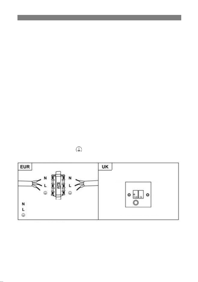
WARNING: This i
s a Class I appliance and MUST be earthed This
appliance is supplied with a 3 core mains cable colo ured as follows:
Brown = L or Live
Blue = N or Neutral
Green and Yellow = E or Earth
The fuse must be rated at 3 Amps.
Page 6

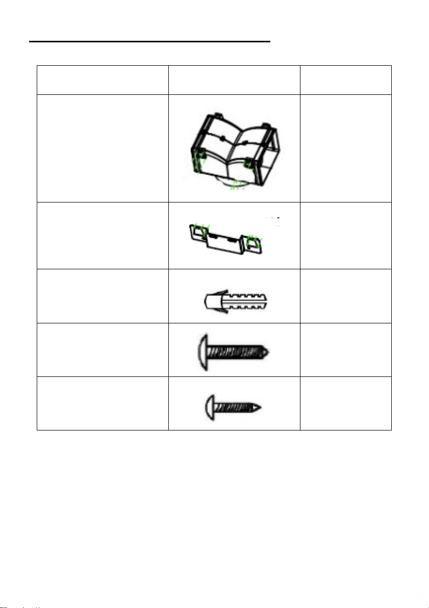
Standard Installation Accessories List
Spec.
Illustration Picture
Qty
6
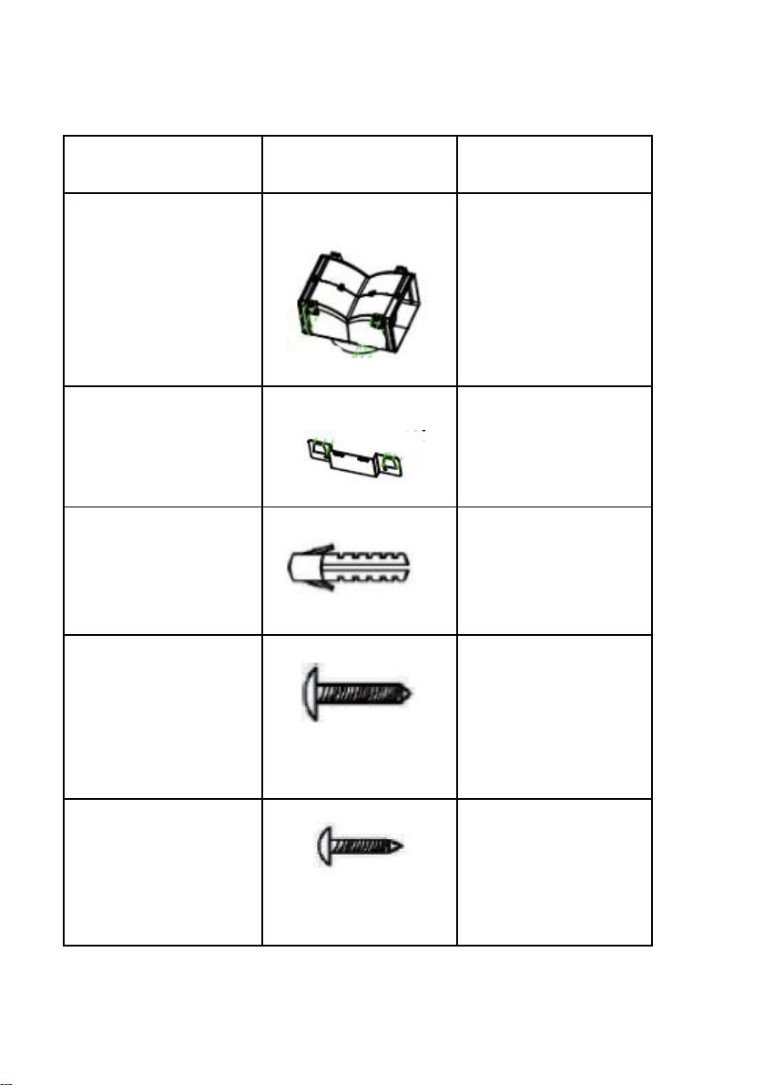
Hood body 1
Lower chimney
(500mm)
Upper chimney
(500mm)
Upper chimney
bracket
Lower chimney
bracket
Cooker hood bracket 1
φ8 rawl plugs φ8×φ6
white color
Screw (ST4 * 30 mm)
Screw (ST4 * 8 mm)
Air outlet
1
1
1
1
9
9
6
1
Carbon filter 2
Page 7

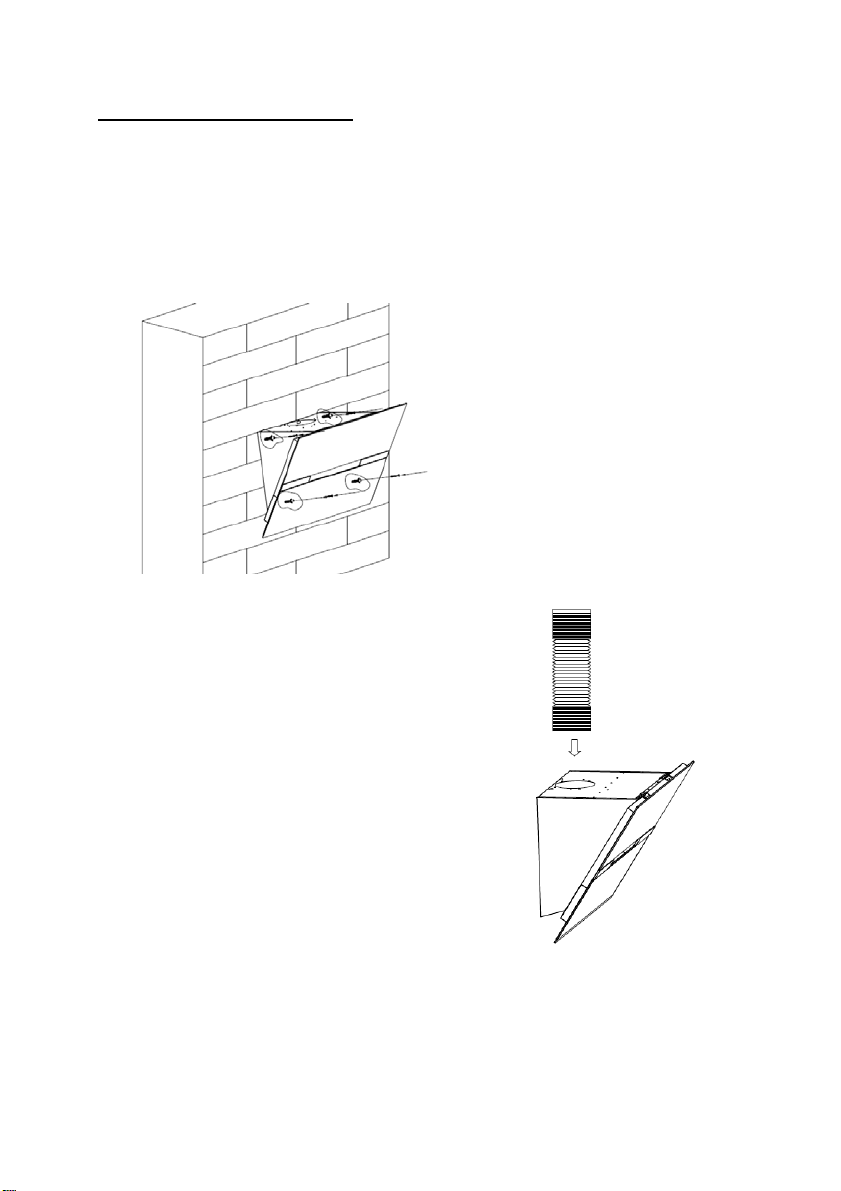
INSTALLATION (wall mounting)
7
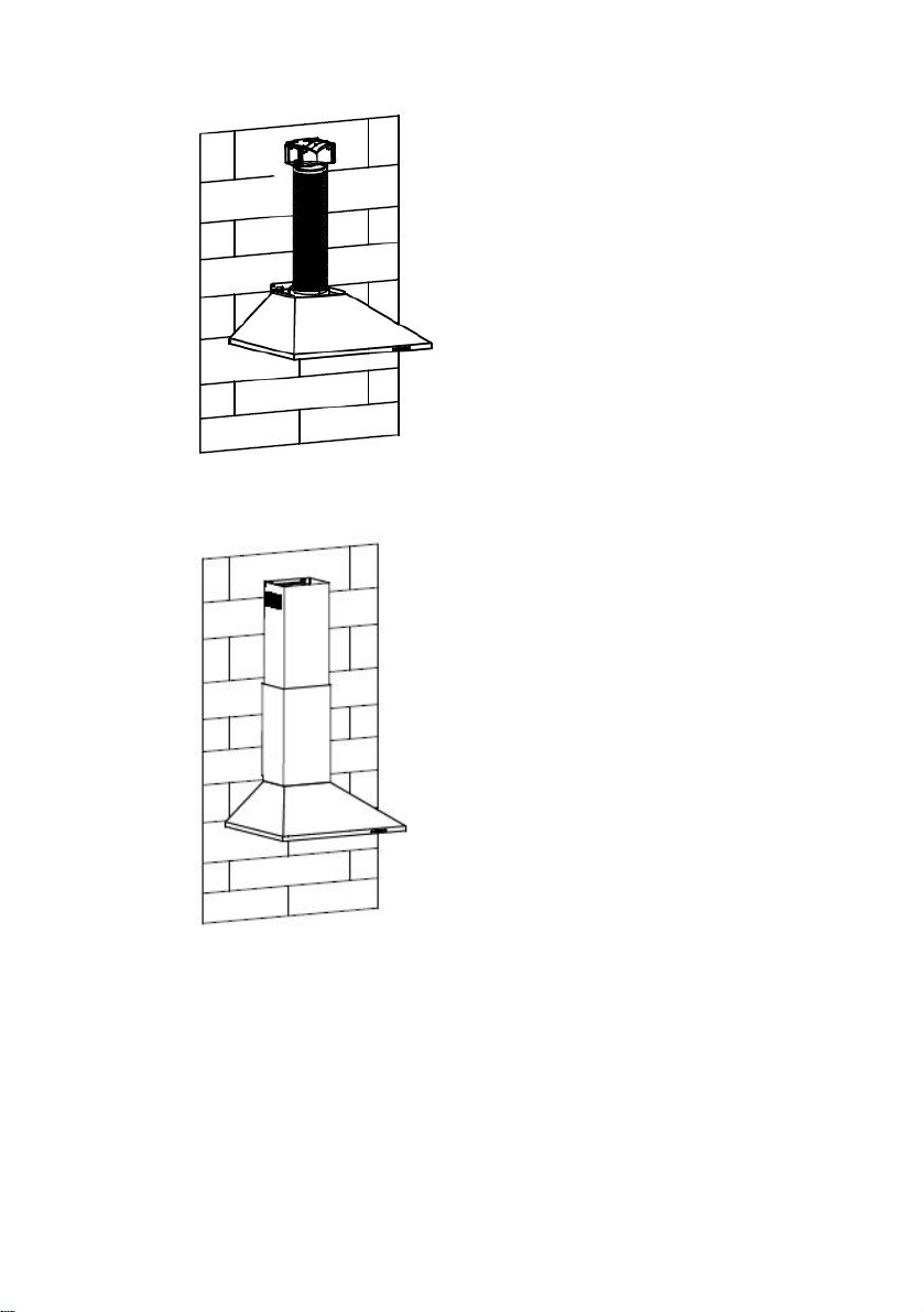
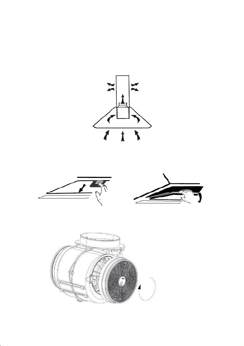
If you have an outlet to the outside, your cooker hood can be connected as
below picture by means of an extraction duct (enamel, aluminum, flexible pipe
non flammabe with an interior diameter of 150mm )
1. Before installation, turn the unit off and unplug it from the outlet.
2. The cooker hood should be placed at a distance of 65~75c
m above
the cooking plane for best effect.
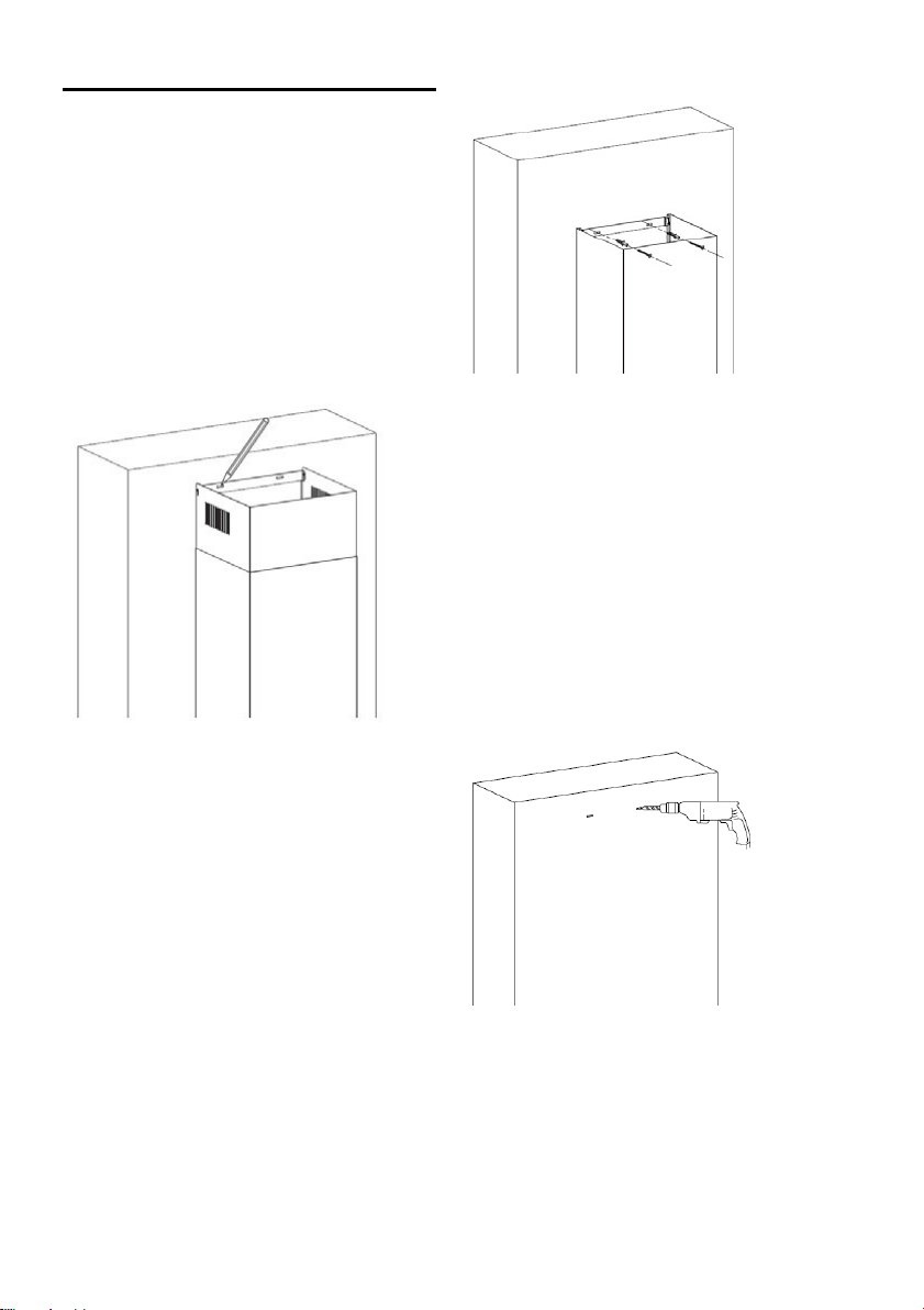
Page 8

INSTALLING THE HOOD
8
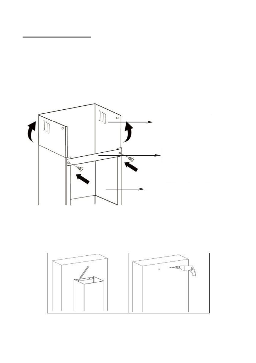
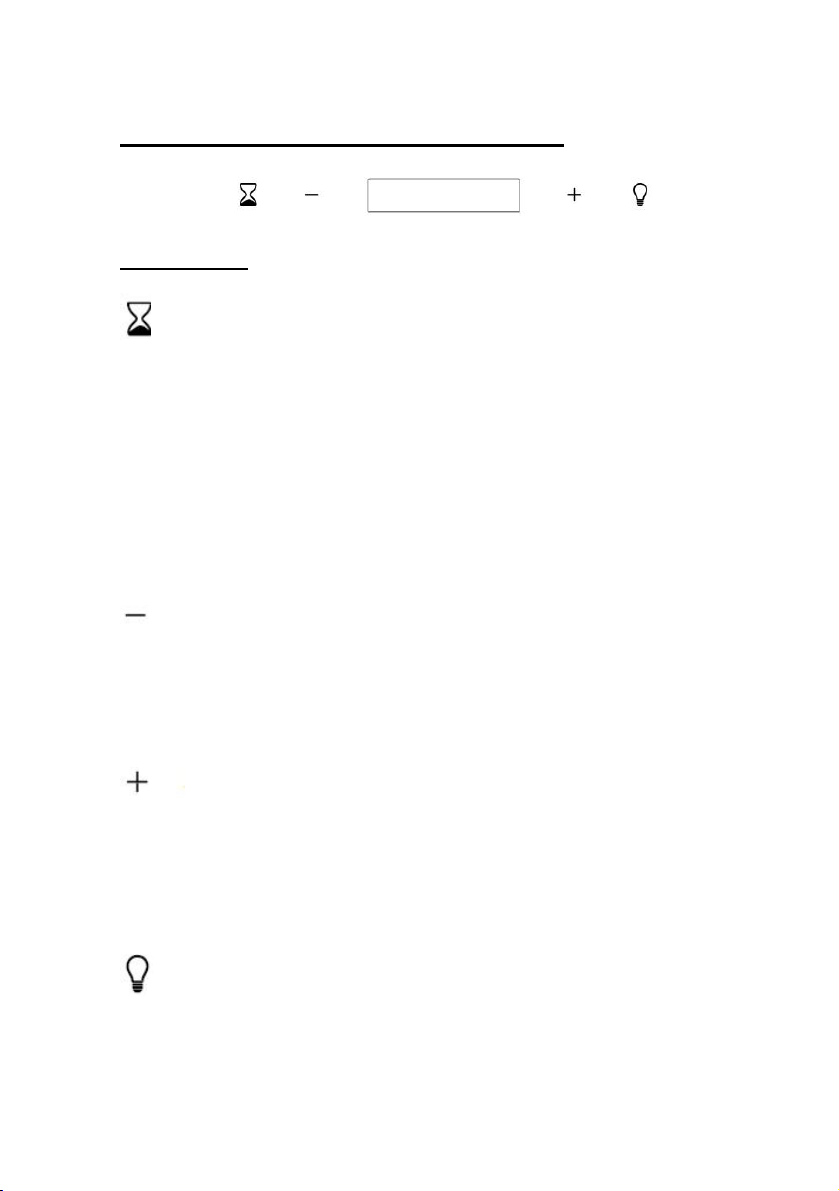
Position the hood at the desired hei
ght respecting the minimum height
above the hob.
Mark the location of the wall bracket.(Placed the holes between 700 and
800 mm above the worktop) Remove the hood and position the wall bracket
to mark the locations of the holes on the wall.
Drill the 3 holes in the wall to insert the appropriate fastening system (screw
ST4x30mm)..
Hang the hood in the notch
es of the wall
bracket.
Page 9
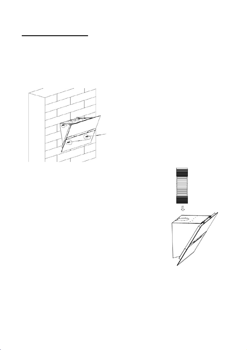
INSTALLING THE HOOD
9
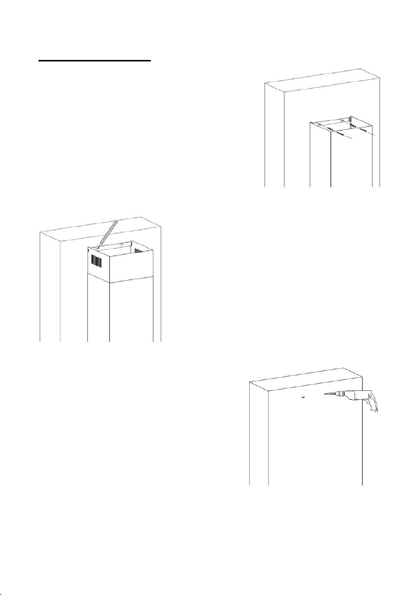
Once the hood is in place, locate the location of the 4 additi onal wall mount
screws as shown in the following diagram.
Remove the hood to puncture the wall and install wall plugs.
Secure the body of the hood with 4 screws of 4 mm in diamet er using
dowels adapted to your wall.
If the extraction mod
e is selected, place the
exhaust air duct on the air outlet as shown.
Page 10

INSTALLING THE HOOD
10
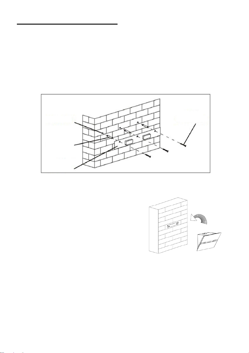
Attach the lower chimney support to the lower chimney as shown.
Use 2 screws ST4x8mm.
(Do not over tighten the screws, make sure the upper chimney can slide
easily into the lower chimney)
Insert the upper chimney into the lower chimney.
Position the bottom chi
mney in the appliance, then mark the holes on the
wall.
Remove the lower chimney, then drill holes in the wall: hole for screw
diameter Φ8 mm
Use the dowels adapted to your wall
Page 11

INSTALLING THE HOOD
11
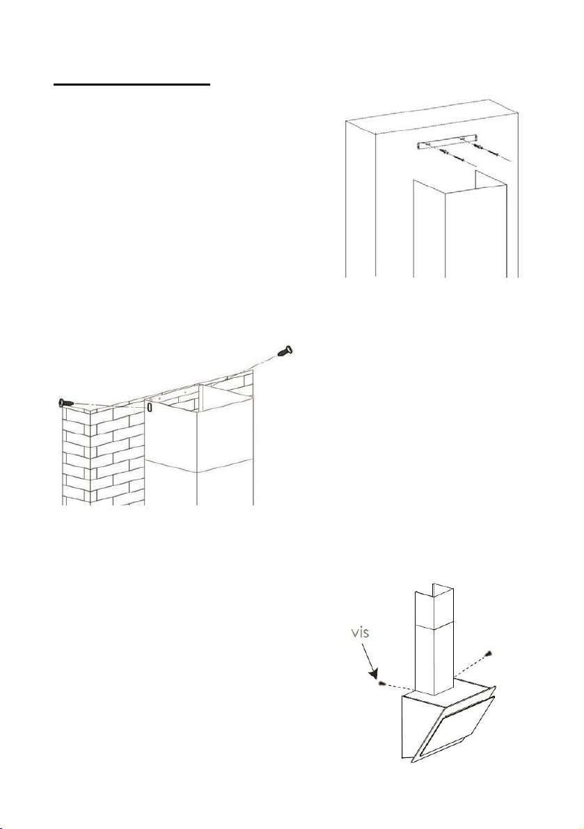
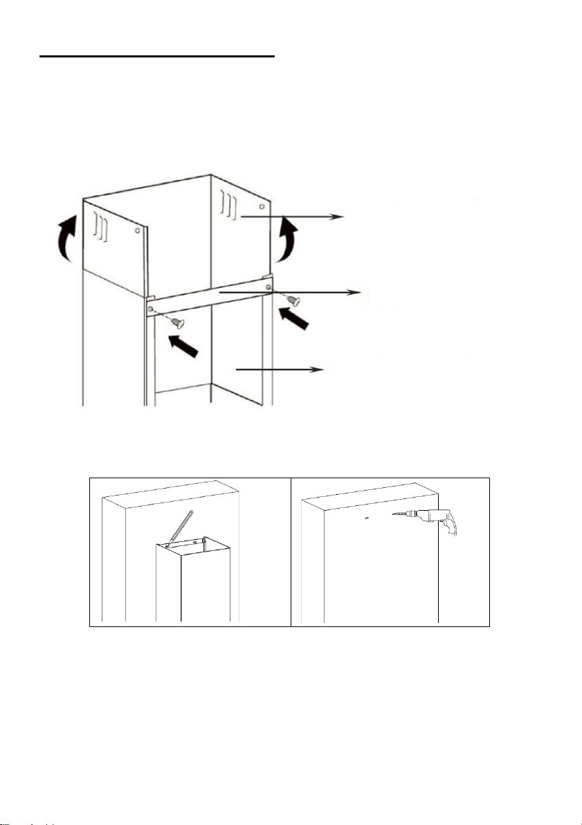
Install the lower chi
mney, then screw it to
the wall with 2 screws of diameter Φ 8 mm
Then pull the upper chimney upwards
to the desired height. Mark the
locations of the mounting holes of the
upper chimney support.
Lower the upper chimney
and then drill
holes in the wall.
Insert the dowels adapted to your wall
Page 12

INSTALLING THE HOOD
12
Secure the wall bracket of the upper
chimney to the wall using the selected
dowels (8 mm screws recommended).
Reassemble the upper
chimney and fix it to the wall
bracket with 2 screws
ST4x8mm
Fasten the lower chimney to the lugs of the
kitchen hood using 2 screws ST4x8mm.
Page 13

Standard Installation Accessories List
13
Spec. Illustration Picture Qty
Air Deflector
Bracket
φ8 rawl plugs
φ8×φ6 white color
1
1
2
Screws
Screws
ST4.0×30
ST3.5×12
2
2
Page 14

INSTALLATION(AIR DEFLECTOR FOR T-SHAPE,CURVED
14
GLASS,FLAT GLASS MODELS):
Air deflector is mentioned as included and not optional.
1. Fix the bracket to the T-shaped plastic o
screws provided as shown below:
2. Drill 2 holes on the wall to accommodate the wall plugs,then screw and
tighten the bracket onto the wall with 2pcs ST4x30mm screws provided.
utlet with 2pcs ST3.5x12mm
3. Attach the exhaust pipe onto the air o
below:
utlet of the cooker hood as shown
Page 15

4. Install the chimney to the unit and fix it.
15
o “Please kindly be noted: T-sha
ped plastic outlet and v-flaps can not
be use d at the same time. You can use them in two ways: 1) Add vflap on existing o utlet; 2) Use T-shaped plastic outlet, no add v-flap.”
o “Note: The product is prov
ided with v-flap accessory. This accessory
is not mandatory for installation, operation and use of the product.”
Page 16

INSTALLATION (VENT INSIDE)
16
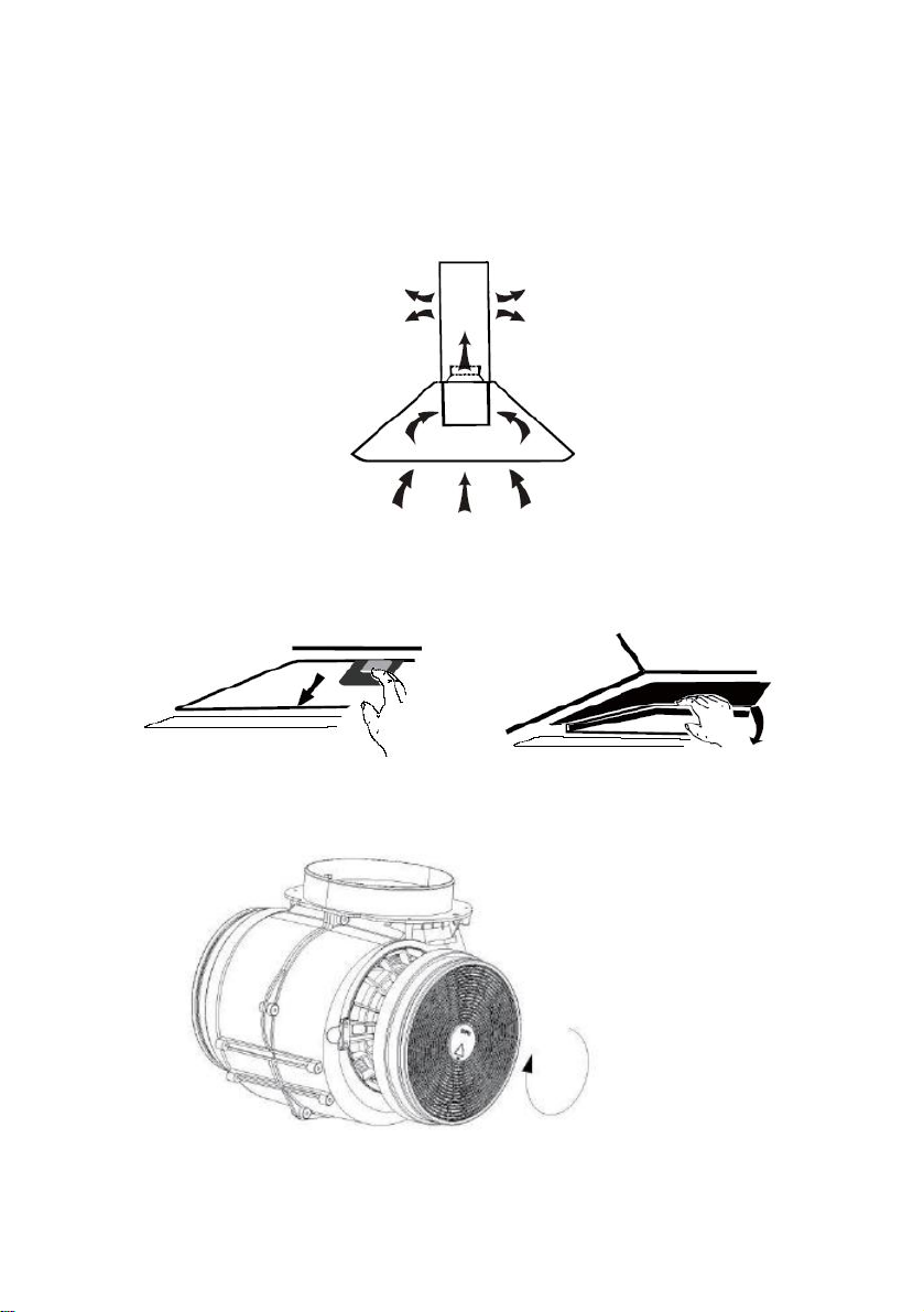
If you do not have an outlet to the outside, exhaust pipe is not required and
the installation is similar to the one show in section “INSTALLATION (VENT
OUTSIDE)”.
Activated carbon filter can
be used to trap odors.
In order to install the activated carbon filter, the grease filter should be
detached first. Press the lock and pull it downward.
Plug the activated carbon filter into the unit and turn it in clockwise direction.
Repeat the same on the other side.
NOTE:
o Make sure the filter is securely locked. Otherwise, it would loosen and
cause dangerous.
o When activated carbon filter attached, the suction power will be
lowere
Page 17
DESCRIPTION OF COMPONENTS
17
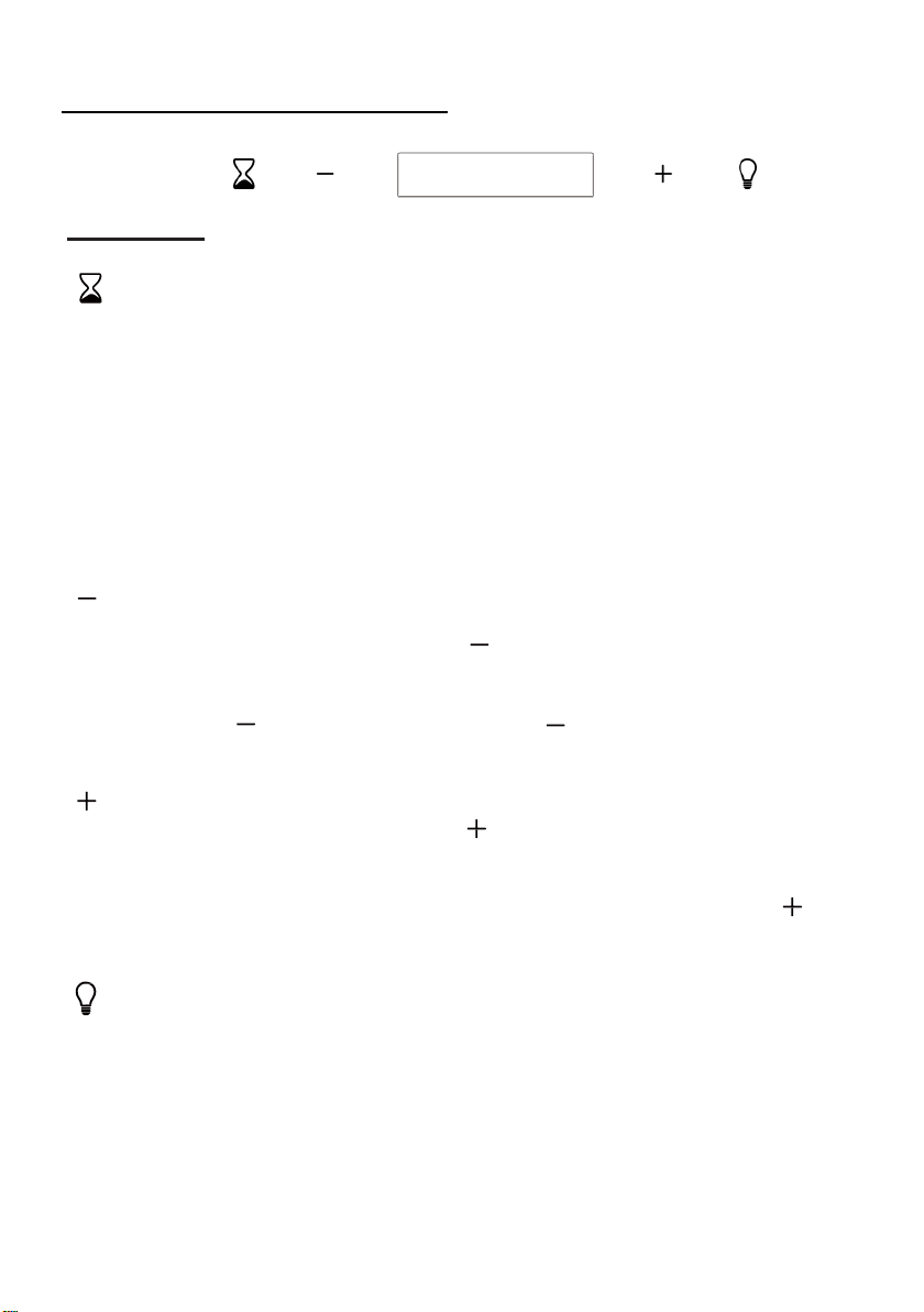
OPERATION
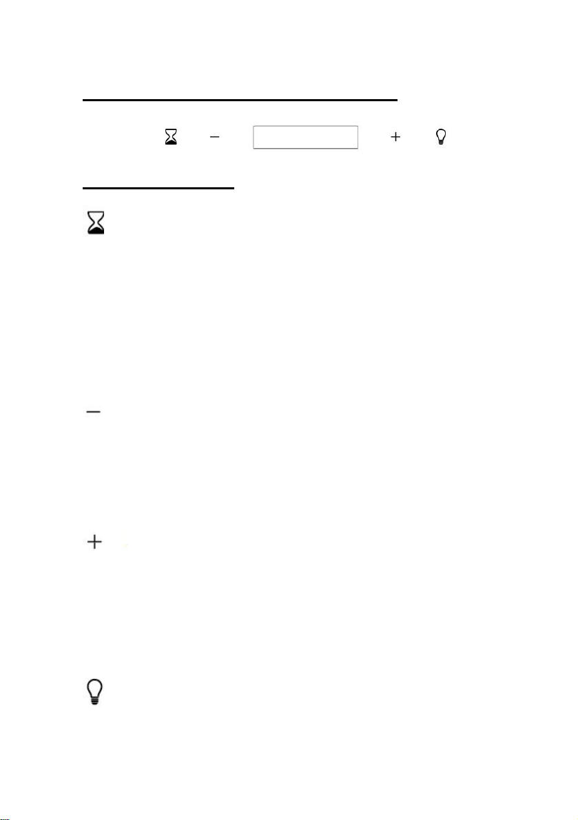
Timer button
1. Setting the time of the day
When hood in standby mode (motor not working), press the timer button to
enter the time setting.
Press the ‘Fan speed’ key to set the hour of the day and press the
‘Light ‘key to set the minute.
2. Setting the Timer
When the hood is in operation mode, press the timer button to
set the countdown.
Press the timer button one timer then the countdown will increase one
minute. The max countdown is 60 minutes.
Speed decrease button
The button is with indicate backlit, - for increasing the speed of the fan
or turn off the fan; when you press the button from speed 3 and the
backlit is on, the fan will be decreasing the speed from speed 3-2-1 by
press the - button, when you press the - button from speed 1, the
fan will be in standby mode. and the backlit will be turned off.
Speed plus button
The button is with indicate backlit, + for turn on the fan or increasing the
speed of the fan when you long press the button at standby mode, the
backlit will be turned on and the fan will be turned on at low speed. then
the fan will be increasing the speed from speed 1-2-3 by press the +
button
LIGHT Button
For lighting ON & OFF.
Page 18

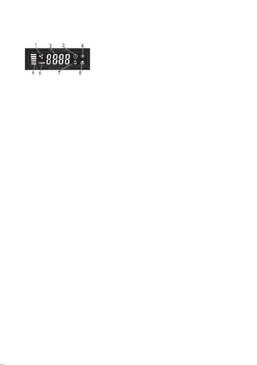
LCD display
18
1. Motor symbol, will rotate when the motor is
working;
2. Time display;
3. Timer symbol, will appear when timer is setting
and counting;
4. Light symbol;
5. Motor speed;
6. Turbo speed symbol, will appear when the speed
is highest setted;
7. Alarm symbol, will appear 5 seconds when the
counting down of timer is over.
8. Cleanning alarm, appear when total working time
up to 14 hours or at the first time using after
pluging.
Page 19
MAINTENANCE
19
Before cleaning switch the unit off and pull out the plug.
I. Regular Cleaning
Use a soft c
household cleaning detergent. Never use metal pads, chemical, abrasive
material or stiff brush to clean the unit.
loth moistened with hand-warm mildly soapy water or
II. Monthly Cleaning for Gr
ESSENTIAL: Clean the filter every month can prevent any risk of fire.
The filter collects grease, smoke and dus
affecting the efficiency of the cooker hood. If not cleaned, the grease
residue (potential flammable) will saturate on the filter. Clean it with
household cleaning detergent.
III. Annual Cleaning for Activated Carbon Filter
Apply SOLELY to unit that installed as a recirculation unit (not vented to
the outside). This filter traps odors and must be replaced at least once a
year
depending on how frequent the cooker hood used.
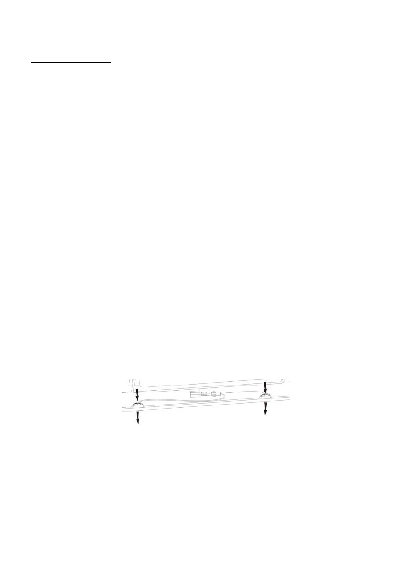
IV. Changing a light bulb
Remove the screws on the glass, take off the hood glass. Find the bulb
that requires replacement, you will find it located in the light fixture which
is inside the exposed section of the canopy.
ease Filter
t…... so the filter is directly
Disconnect the light wiring point and remove the bulb holders and
wiring from the hood. Important: It’s not possible to replace the
bulbs individually, it will be necessary to obtain the bulbs, bulb
holders and wiring as a complete part. (LED light: MAX 1.5W)
Fit the replacement bulbs, bulb holders and wiring in the same
manners as the originals. Then reconnect the light wiring point.
Page 20
Refit the hood glass and fasten the glass screws. Make sure the screws
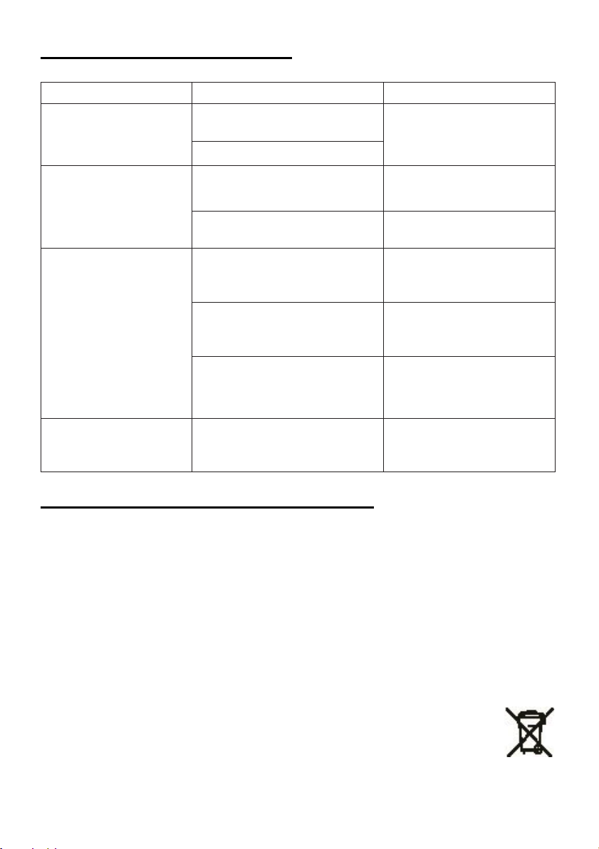
Fault
Cause
Solution
Light on, but
work
The fan blade is
jammed.
The motor is damaged.
Both light and
work
Replace the bulb with correct
rating.
Power cord looses.
Plug in to the power supply again.
The fan blade is
damaged.
Switch of the unit and repair by
qualified service personnel only.
The fan motor is not
fixed tightly.
Switch off the unit and repair by
qualified service personnel only.
Take down the unit and check
location.
Suction
not good
Too long distance
the cooking plane
20
are fully tightened.
TROBULESHOOTING
fan does not
fan do not
Serious
Vibration of
the unit
performance
Halogen light bulb burn.
The unit is not hung
properly on the bracket.
between the unit and
CUSTOMER ASSISTANCE SERVICE
If you cannot identify the cause of the operating anomaly, switch off the
appliance and contact the Assistance Service.
PRODUCT SERIAL NUMBER. Where can I find it?
It is important you to inform the Assistance Service of your product code
and its serial number (a 16 character code which begins with the number 3);
this can be found on the guarantee certificate or on the data plate located
on the appliance.
It will help to avoid wasted journeys to technicians, thereby (and most
significantly) saving the corresponding callout charges.
Switch off the unit and repair by
qualified service personnel only.
whether the bracket is in proper
Readjust the distance to 65-75cm
This appliance is marked acc
2012/19/EU on Waste Electrical and Electronic Equipment
(WEEE).
WEEE contains both polluting substances (which can cause
negative consequences for the environment) and basic components (which
can be re-used). It is important to have WEEE subjected to specific
ording to the European directive
Page 21

treatments, in order to remove and dispose properly all pollutants, and
21
recover and recycle all materials.
Individuals can play an important role in ensuring that WEEE does not
become an environmental issue; it is essential to follow some basic rules:
WEEE should not be treated as household waste;
WEEE should be handed over to the relevant collection points managed by
the municipality or by registered companies. In many countries, for large
WEEE, home collection could be present.
In many countries, when you buy a new appliance, the old one may be
returned to the retailer who has to collect it free of charge on a one-to-one
basis, as long as the equipment is of equivalent type and has the same
functions as the supplied equipment.
Page 22

MANUAL DE INSTALACIÓN Y USO
22
CONTENIDO
INTRODUCCIÓN
PRECAUCIÓN DE SEGURIDAD
INSTALACIÓN ELÉCTRICA
ESPECIFICACIÓN
INSTALACIÓN (VENTILACIÓN EXTERIOR)
INSTALACIÓN (VENTILACIÓN EN EL INTERIOR)
DESCRIPCIÓN DE LOS COMPONENTES
FUNCIONAMIENTO
MANTENIMIENTO
SOLUCIÓN DE PROBLEMAS
CONFORMIDAD CON LAS DIRECTIVAS
PROTECCIÓN DEL MEDIO AMBIENTE
23
23
25
26
27
36
37
37
39
40
40
41
Page 23

INTRODUCCIÓN
23
Gracias por elegir esta campana de cocina.
Este manual de instrucciones está diseñado para proporcionarle todo lo
necesario con instrucciones relacionadas con la instalación, el uso y el
mantenimiento del aparato. Con el fin de operar el aparato correctamente y con
seguridad, por favor lea este manual de instrucciones cuidadosamente antes de
la instalación y el uso.
La campana extractora utiliza materiales de alta calidad y está fabricada con un
diseño aerodinámico. Equipada con un motor eléctrico de gran potencia y un
ventilador centrífugo, también proporciona una fuerte potencia de succión, un
funcionamiento de bajo ruido, un filtro de grasa antiadherente y una instalación
de fácil montaje.
Declaramos, por nuestra cuenta responsabilidad, el cumplimiento de todos los
requisitos europeos de seguridad, salud y medio ambiente establecidos en la
legislación de este producto.
PRECAUCIÓN DE SEGURIDAD
Nunca dejes que los niños operen la máquina.
La campana extractora es sólo para uso doméstico, no es adecuada para
barbacoas, asadores y otros fines comerciales.
La campana extractora y su filtro deben ser limpiados regularmente para
mantenerlos en buenas condiciones de funcionamiento.
Limpie la campana extractora de acuerdo con el manual de instrucciones y
evite que el aparato se queme.
Prohíba el horneado directo de la cocina de gas. Por favor, mantenga una
buena convección en la cocina.
Antes de conectar el aparato, compruebe que el cable de alimentación no
esté dañado. Un cable de alimentación dañado sólo debe ser sustituido por
personal de servicio técnico cualificado.
La habitación deberá estar suficientemente ventilada cuando la campana
extractora se utilice al mismo tiempo que los aparatos de gas u otros
combustibles;
El aire no debe descargarse en una chimenea que se utilice para expulsar los
gases de los aparatos que queman gas u otros combustibles;
Deben cumplirse las normas relativas a la descarga de aire.
Los niños deben ser supervisados para asegurarse de que no jueguen con el
aparato.
No flamee bajo la campana extractora.
La campana extractora no está diseñada para ser instalada sobre una placa
de cocina que tenga más de cuatro elementos.
que haya una ventilación adecuada de la sala cuando la campana extractora
se utilice al mismo tiempo que los aparatos de gas u otros combustibles (no
aplicable a los aparatos que sólo devuelven el aire a la sala); los detalles
relativos al método y la frecuencia de la limpieza
Page 24

existe un riesgo de incendio si la limpieza no se realiza de acuerdo con las
24
instrucciones
no encienda fuego bajo la campana de la cocina
PRECAUCIÓN: Las partes accesibles pueden calentarse cuando se usan con
aparatos de cocina.
Peligro de choque eléctrico
Peligro de choque eléctrico
Enchufe esta unidad sólo en una toma de corriente con conexión a tierra. En
caso de duda, pida consejo a un ingeniero debidamente cualificado.
El incumplimiento de estas instrucciones puede provocar la muerte, un
incendio o una descarga eléctrica.
Page 25
Instalación eléctrica
(Azul)
(Marrón)
(Verde y amarillo)
DOBLE POLO CONMUTADO
BEZPIECZNIKIEM
CON SALIDA SPURFUSIBLE
25
Toda instalación debe ser realizada por una persona competente o un electricista
cualificado. Antes de conectar la alimentación de la red, asegúrese de que la
tensión de la red corresponda a la tensión que figura en la placa de
características.
Conexión directa
El aparato debe conectarse directamente a la red eléctrica mediante un interruptor
omnipolar con una apertura mínima de 3 mm entre los contactos.
El instalador debe asegurarse de que se ha realizado la conexión eléctrica
correcta y que ésta se ajusta al esquema de cableado.
El cable no debe estar doblado ni comprimido.
Compruebe regularmente que el enchufe y el cable de alimentación no estén
dañados. Si el cable de alimentación está dañado, debe ser sustituido por un
cable o conjunto especial disponible en el fabricante o su agente de servicio.
ADVERTENCIA: Este es un aparato de clase I y DEBE estar conectado a tierra
Este aparato se suministra con un cable de alimentación de 3 hilos del siguiente
color:
Marrón = L o Vivo
Azul = N o Neutro
Verde y amarillo = E o Tierra
El fusible debe tener una capacidad de 3 amperios.
Page 26

Lista de accesorios de instalación estándar
Espec.
Imagen
CANTIDAD
Cuerpo de la campana
1
Chimenea inferior (500mm)
1
Chimenea superior (500mm)
1
26
Soporte superior de la
chimenea
El soporte inferior de la
chimenea
Soporte de la campana de la
cocina
φ8 taco φ8×φ6 color blanco
Tornillo (ST4 * 8 mm)
Tornillo (ST4 * 30 mm)
Salida de aire
Filtro de carbono
1
1
1
9
9
6
1
2
Page 27

INSTALACIÓN (montaje en la pared)
27
Si tiene una salida al exterior, su campana extractora puede ser conectada como en
la foto de abajo por medio de un conducto de extracción (esmalte, aluminio, tubo
flexible no inflamable con un diámetro interior de 150mm)
1. Antes de la instalación, apague la unidad y desenchúfela de la toma de
corriente.
2. La campana extractora debe ser colocada a una distancia de 65~75cm sobre
el plano de cocción para un mejor resultado.
Page 28

INSTALACIÓN DE LA CAMPANA
Tornillo
(4mmx30mm)
28
Coloca la campana a la altura deseada respetando la altura mínima sobre la placa.
Marque la ubicación del soporte de pared. (Coloque los agujeros entre 700 y 800
mm por encima de la encimera) Retire la campana y coloque el soporte de pared
para marcar la ubicación de los agujeros en la pared. Perfore los 3 agujeros de la
pared para insertar el sistema de fijación adecuado (tornillo ST4x30mm).
agujeros en la
pared
enchufe de
pared
campana
extractora
Cuelgue la campana en las muescas del
soporte de la pared.
Page 29

INSTALANDO LA CAMPANA
29
Una vez que la campana esté en su lugar, localice la ubicación de los 4 tornillos
adicionales de montaje en la pared como se muestra en el siguiente diagrama.
Retire la campana para perforar la pared e instale los tacos de la pared. Asegure
el cuerpo de la campana con 4 tornillos de 4 mm de diámetro utilizando tacos
adaptados a su pared.
Si se selecciona el modo de extracción, coloque el
conducto de aire de salida en la salida de aire como se
muestra.
Page 30

INSTALANDO LA CAMPANA
30
Ate el soporte de la chimenea inferior a la chimenea inferior como se muestra.
Utilice 2 tornillos ST4x8mm. (No apriete demasiado los tornillos, asegúrese de
que la chimenea superior pueda deslizarse fácilmente en la chimenea inferior)
Inserte la chimenea superior en la chimenea inferior.
chimenea superior
(interior)
soporte de chimenea
inferior
chimenea inferior (exterior)
Coloca la chimenea inferior en el aparato y marca los agujeros en la pared.
Quitar la chimenea inferior, y luego perforar los agujeros en la pared: agujero para
el tornillo diámetro Φ8 mm
Use las clavijas adaptadas a su pared.
Page 31

INSTALANDO LA CAMPANA
31
Instalar la chimenea inferior, luego atornillarla a la
pared con 2 tornillos de diámetro Φ 8 mm.
Luego tire de la chimenea superior hacia arriba
hasta la altura deseada. Marque la ubicación de
los agujeros de montaje del soporte de la
chimenea superior.
Bajar la chimenea superior y luego hacer
agujeros en la pared.
Inserte las clavijas adaptadas a su pared.
Page 32

INSTALANDO LA CAMPANA
32
Asegure el soporte de la chimenea superior
a la pared con los tacos seleccionados (se
recomiendan tornillos de 8 mm).
Reensamblar la chimenea
superior y fijarla al soporte de la
pared con 2 tornillos ST4x8mm
Fijar la chimenea inferior a las lengüetas de
la campana de la cocina con 2 tornillos
ST4x8mm.
Page 33
Lista de accesorios de instalación estándar
Espec.
Imagen
CANTIDAD
Deflector de aire
1
Soporte
1
φ8 tacos φ8×φ6 color
blanco
2
Tornillos ST4.0×30
2
Tornillos ST3.5×12
2
33
Page 34

INSTALACIÓN (DEFLECTOR DE AIRE PARA MODELOS CON
34
FORMA DE T, VIDRIO CURVO, VIDRIO PLANO):
El deflector de aire se menciona como incluido y no como opcional.
Fijar el soporte a la salida de plástico en forma de T con 2pcs
1.
ST3.5x12mms tornillos proporcionados como se muestra a continuación:
2. Taladrar 2 agujeros en la pared para acomodar los tacos, luego atornillar y
apretar el soporte en la pared con 2 pcs de tornillos ST4x30mm provistos.
3. Coloque el tubo de extracción en la salida de aire de la campana extractora
como se muestra a continuación:
Page 35
4. Instala la chimenea a la unidad y arréglala.
35
"Por favor, tenga la amabilidad de tomar nota: La salida de plástico en
forma de T y las aletas en V no pueden ser usadas al mismo tiempo.
Puedes usarlas de dos maneras: 1) Agregar v-flap en la salida existente;
2) Usar la salida de plástico en forma de T, sin agregar v-flap."
"Nota: El producto se suministra con el accesorio v-flap. Este accesorio
no es obligatorio para la instalación, operación y uso del producto".
Page 36
INSTALACIÓN (VENTILACIÓN EN EL INTERIOR)
36
Si no tiene una salida al exterior, no se requiere un tubo de escape y la
instalación es similar a la que se muestra en la sección "INSTALACIÓN (SALIDA
AL EXTERIOR)".
El filtro de carbón activado puede utilizarse para atrapar olores. Para instalar el
filtro de carbón activado, primero hay que quitar el filtro de grasa. Presione el
bloqueo y tire de él hacia abajo.
Enchufe el filtro de carbón activado en la unidad y gírelo en el sentido de las
agujas del reloj. Repita lo mismo en el otro lado.
KIERUNEK ZAMYKANIA
NOTA:
o Asegúrate de que el filtro esté bien cerrado. De lo contrario, se aflojaría y
sería peligroso.
o Cuando el filtro de carbón activado está conectado, la potencia de succión
será menor.
Page 37
DESCRIPCIÓN DE LOS COMPONENTES
37
FUNCIONAMIENTO
Botón del temporizador
1. Ajustar la hora del día
Cuando la campana esté en modo de espera (el motor no funciona),
pulse el botón del temporizador para entrar en el ajuste de la hora.
Presione la tecla 'Fan speed' para ajustar la hora del día y presione la
tecla 'Light' para ajustar los minutos.
2. Ajuste del temporizador
Cuando la campana esté en modo de funcionamiento, pulse el botón
del temporizador para iniciar la cuenta atrás. La cuenta atrás máxima
es de 60 minutos.
Botón de disminución de la velocidad
El botón está con indicación de retroiluminación, — para aumentar la
velocidad del ventilador o apagar el ventilador; cuando presione el botón
desde la velocidad 3 y la retroiluminación esté encendida, el ventilador
estará disminuyendo la velocidad desde la velocidad 3-2-1 al presionar el
botón —, cuando presione el botón — desde la velocidad 1, el ventilador
estará en modo de espera. y la retroiluminación se apagará.
Botón de velocidad plus:
El botón está con indicación de retroiluminación, + para encender el
ventilador o aumentar la velocidad del ventilador cuando se pulsa durante
mucho tiempo el botón en el modo de espera, la retroiluminación se
encenderá y el ventilador se encenderá a baja velocidad. entonces el
ventilador aumentará la velocidad desde la velocidad 1-2-3 mediante la
pulsación del botón +.
Botón de luz
Botón de luz para encender y apagar la luz.
Page 38
DISPLAY LCD
38
1. El símbolo del motor, girará cuando el
motor esté funcionando;
2. Visualización de la hora;
3.El símbolo del temporizador, aparecerá
cuando el temporizador se esté ajustando
y contando;
4. Símbolo de la luz;
5. Velocidad del motor;
6. El símbolo de la velocidad del turbo,
aparecerá cuando la velocidad sea la más
alta establecida;
7. Símbolo de alarma, aparecerá 5
segundos cuando la cuenta atrás del
temporizador termine.
8. Alarma de limpieza, aparecerá cuando el
tiempo total de trabajo sea de hasta 14
horas o cuando se utilice por primera vez
después de enchufar.
Page 39

MANTENIMIENTO
39
Antes de la limpieza, apague la unidad y saque el enchufe.
I. Limpieza regular
Use un paño suave humedecido con agua jabonosa tibia o detergente de limpieza
para el hogar. Nunca use almohadillas metálicas, químicas, abrasivas material o un
cepillo rígido para limpiar la unidad.
II. Limpieza mensual del filtro de grasa
ESENCIAL: Limpiar el filtro cada mes puede prevenir cualquier riesgo de incendio.
El filtro recoge la grasa, el humo y el polvo... ...por lo que el filtro afecta
directamente a la eficiencia de la campana extractora. Si no se limpia, los residuos
de grasa (potencialmente inflamables) se saturarán en el filtro. Límpielo con un
detergente de limpieza doméstico.
III. Limpieza anual del filtro de carbón activado
Aplicar SOLAMENTE a la unidad que se instaló como unidad de recirculación (no
ventilada al exterior). Este filtro atrapa los olores y debe ser reemplazado al menos
una vez al año dependiendo de la frecuencia con la que la campana de la cocina
se utiliza.
IV. Cambiar una bombilla
Quita los tornillos del cristal, quita el cristal de la campana. Encuentra la bombilla
que requiere ser reemplazada, la encontrarás ubicada en la lámpara que está
dentro de la sección expuesta del capó.
Desconecte el punto de cableado de la luz y retire los soportes de la bombilla y
el cableado de la campana. Importante: No es posible reemplazar las bombillas
individualmente, será necesario obtener las bombillas, los portalámparas y el
cableado como una pieza completa. (Luz LED: MAX 1.5W)
Coloca las bombillas de repuesto, los portalámparas y el cableado de la misma
manera que los originales. Luego reconecte el punto de cableado de la luz.
Vuelva a colocar el vidrio de la campana y apriete los tornillos del vidrio.
Asegúrate de que los tornillos estén completamente apretados.
Page 40
SOLUCIONADOR DE PROBLEMAS
FALLO
CAUSA
SOLUCION
La luz se
enciende, pero el
ventilador no
funciona
La aspa del ventilador está
atascada.
Apague la unidad y repárela sólo por
personal de servicio calificado.
El motor está dañado.
Tanto la luz
como el
ventilador no
funcionan
Se queman las bombillas
halógenas.
Reemplaza la bombilla con la
clasificación correcta.
El cable de alimentación se
suelta.
Enchúfalo a la fuente de alimentación
de nuevo.
Vibración grave
de la unidad
La aspa del ventilador está
dañada.
Cambio de la unidad y reparación por
personal de servicio calificado
solamente.
El motor del ventilador no está
bien fijado.
Apague la unidad y repárela sólo por
personal de servicio calificado.
La unidad no está bien colgada
en el soporte.
Desmonta la unidad y comprueba si
el soporte está en su sitio.
El rendimiento de
la succión no es
bueno
Demasiada distancia entre la
unidad y el plano de cocción
Reajuste la distancia a 65-75cm
más importante) los correspondientes gastos de llamada.
Este aparato está marcado de acuerdo con la directiva
europea 2012/19/UE sobre residuos de aparatos eléctricos y
electrónicos (RAEE).
40
SERVICIO DE ASISTENCIA AL CLIENTE
Si no puede identificar la causa de la anomalía de funcionamiento, apague el
aparato y póngase en contacto con el Servicio de Asistencia.
NÚMERO DE SERIE DEL PRODUCTO. ¿Dónde puedo encontrarlo?
Es importante que comunique al Servicio de Asistencia el código del producto y
su número de serie (un código de 16 caracteres que comienza con el número
3); éste se encuentra en el certificado de garantía o en la placa de datos
situada en el aparato.
Esto ayudará a evitar viajes inútiles a los técnicos, ahorrando así (y lo que es
Los RAEE contienen ambas sustancias contaminantes (que pueden causar
consecuencias negativas para el medio ambiente) y componentes básicos (que
pueden ser reutilizados). Es importante que los RAEE se sometan a unapara
Page 41

eliminar y eliminar adecuadamente todos los contaminantes, y recuperar y
41
reciclar todos los materiales.
Los individuos pueden desempeñar un papel importante para asegurar que los
RAEE no se conviertan en un problema ambiental; es esencial seguir algunas
reglas básicas:
Los RAEE no deben tratarse como residuos domésticos;Los RAEE deben
entregarse en los puntos de recogida correspondientes gestionados por el
municipio o por empresas registradas. En muchos países, en el caso de los
RAEE de gran tamaño, la recogida domiciliaria podría estar presente.
En muchos países, cuando se compra un nuevo aparato, el antiguo puede
devolverse al minorista, que debe recogerlo gratuitamente en forma individual,
siempre que el aparato sea de tipo equivalente y tenga las mismas funciones
que el suministrado.
Page 42

INSTRUKCJA OBSŁUGI I INSTALACJI
42
SPIS TREŚCI
WPROWADZENIE…………………………………………………….... 43
ŚRODKI OSTROŻNOŚCI……………………………………………... .43
INSTALACJA ELEKTRYCZNA………………………………………… 45
SPECYFIKACJA TECHNICZNA……………………………………..... 46
INSTALACJA (OBIEG OTWARTY)………………………………...…. 47
INSTALACJA (OBIEG ZAMKNIĘTY)…………………………………..56
OPIS FUNKCJI PANELU STEROWANIA………………………… 57
DZIAŁANIE………………………………………………………………..57
KONSERWACJA…………………………………………………………59
ROZWIĄZYWANIE PROBLEMÓW…………………………………….60
ZGODNOŚĆ Z DYREKTYWAMI
OCHRONA ŚRODOWISKA……………………………………………. 61
60
Page 43

WPROWADZENIE
43
Dziękujemy za wybranie tego okapu kuchennego.
Niniejsza instrukcja obsługi zawiera wszystkie niezbędne wskazówki związane z
instalacją, użytkowaniem i konserwacją urządzenia.
W celu prawidłowej obsługi urządzenia i zapewnienia bezpieczeństwa, przed
instalacją i rozpoczęciem użytkowania należy uważnie przeczytać instrukcję
obsługi.
Okap kuchenny został wykonany z materiałów wysokiej jakości i posiada
minimalistyczny kształt. Został wyposażony w silnik elektryczny o dużej mocy
oraz wentylator promieniowy, które zapewniają dużą moc ssania i cichą pracę, a
także filtr przeciwtłuszczowy z nieprzywierającą powłoką. Jest łatwy w montażu.
Umieszczając oznakowanie na tym produkcie, oświadczamy na własną
odpowiedzialność, że produkt jest zgodny ze wszystkimi europejskimi
wymogami dotyczącymi bezpieczeństwa, zdrowia i ochrony środowiska,
określonymi w przepisach mających związek z produktem.
ZASADY BEZPIECZEŃSTWA
Nie wolno pozwalać dzieciom na obsługiwanie urządzenia.
Okap kuchenny jest przeznaczony wyłącznie do użytku domowego; nie nadaje
się do stosowania nad grillem, opiekaczem czy do celów komercyjnych.
Aby utrzymać okap kuchenny w dobrym stanie, obudowa i filtr powinny być
regularnie czyszczone.
Okap kuchenny należy czyścić zgodnie z instrukcją obsługi i zabezpieczyć go
przed działaniem płomieni.
Należy bezwzględnie chronić okap przedwysoką temperaturą płyty gazowej.
Należy zadbać o dobrą wentylację w pomieszczeniu kuchennym.
Przed podłączeniem urządzenia sprawdzić, czy przewód zasilający nie jest
uszkodzony. Uszkodzony przewód zasilający może wymienić wyłącznie
wykwalifikowany personel serwisu technicznego.
Należy zapewnić odpowiednią wentylację pomieszczenia, gdy w tym samym
czasie co okap kuchenny używane jest inne urządzenie spalające gaz lub inne
paliwo;
Wylot okapu nie może być podłączony do komina, który jest używany do
odprowadzania spalin z urządzeń spalających gaz lub inne paliwa;
Należy zapewnić zgodność z przepisami dotyczącymi odprowadzania powietrza.
Dzieci powinny znajdować się pod ciągłym nadzorem, aby mieć pewność, że
nie bawią się urządzeniem.
Pod okapem nie wolno flambirować potraw.
Okap kuchenny nie jest przeznaczony do montażu nad płytą kuchenną
posiadającą więcej niż cztery elementy grzewcze.
Page 44

W pomieszczeniu należy zapewnić odpowiednią wentylację, gdy okap
44
kuchenny jest używany w tymsamym czasie, co urządzenia spalające gaz lub
inne paliwa (nie dotyczy tylko okapów odprowadzających powietrze z
powrotem do pomieszczenia);
Należy przestrzegać instrukcji dotyczących metod i częstotliwości czyszczenia.
Nieprzestrzeganie instrukcji czyszczenia może doprowadzić do wybuchu
pożaru.
Nie używać otwartego ognia pod okapem.
ZACHOWAJ OSTROŻNOŚĆ: Dostępne części mogą się nagrzewać pod
wpływem działania innych urządzeń do gotowania.
Zagrożenie porażeniem prądem
Podłączać urządzenie tylko do prawidłowo uziemionego gniazdka. W razie
wątpliwości należy zasięgnąć porady fachowca z odpowiednimi
uprawnieniami.
Nieprzestrzeganie powyższych wskazówek może spowodować śmierć, pożar
lub porażenie prądem.
Page 45

Instalacja elektryczna
(niebieski)
(brązowy)
(zielony/żółty)
DWUBIEGUNOWE WYJŚCIE Z
BEZPIECZNIKIEM
UŻYWAJ BEZPIECZNIK W 3 A
45
Cała instalacja musi być wykonana przez kompetentną osobę lub
wykwalifikowanego elektryka. Przed podłączeniem zasilania sieciowego upewnij
się, że napięcie sieciowe odpowiada napięciu na tabliczce znamionowej.
Bezpośrednie podłączenie do zasilania
Urządzenie należy podłączyć bezpośrednio do zasilania za pomocą wyłącznika
wielobiegunowego z minimalnym odstępem 3 mm między stykami.
Instalator musi upewnić się, że połączenie elektryczne wykonano prawidłowo, i że
jest ono zgodne ze schematem elektrycznym.
Kabel nie może być zgięty ani przygnieciony.
Regularnie sprawdzaj wtyczkę i przewód zasilający pod kątem uszkodzeń. Jeśli
przewód zasilający jest uszkodzony, należy go wymienić na specjalny przewód lub
zestaw dostępny u producenta lub jego przedstawiciela serwisowego.
OSTRZEŻENIE: Urządzenie należy do Klasy I i MUSI być uziemione. Urządzenie
jest dostarczane z 3-żyłowym kablem zasilającym, z żyłami w następujących
kolorach:
Brązowy = L lub pod napięciem
Niebieski = N lub neutralny
Zielony i żółty = E lub uziemiający
Bezpiecznik musi mieć wartość znamionową 3 A.
Page 46

Lista standardowych akcesoriów instalacyjnych
Część
Ilustracja
Ilość
Obudowa okapu
1
Górny przewód kominowy
(500mm)
1
Dolny przewód kominowy
(500mm)
1
46
Wspornik górnego przewodu
kominowego
Wspornik dolnego przewodu
kominowego
Wspornik do okapu
Kołki rozporowe ø8/6 mm
białe
Wkręty (ST4.0 * 30 mm)
Wkręty (ST4.0 * 8 mm)
Wylot powietrza
Filtr węglowy
1
1
1
9
9
6
1
2
Page 47

INSTALACJA (montaż ścienny)
47
Jeśli posiadasz możliwość odprowadzenia powietrza na zewnątrz, okap kuchenny
można podłączyć w sposób pokazany poniżej, tj. za pomocą przewodu
wentylacyjnego (emaliowanego, z aluminium lub w formie elastycznej rury z
materiału niepalnego o średnicy wewnętrznej 150 mm).
1. Przed instalacją wyłącz urządzenie i wyjmij wtyczkę z gniazdka.
2. Aby uzyskać najlepszą skuteczność, okap kuchenny powinien być
umieszczony w odległości 65 ~ 75 cm nad płytą do gotowania.
Page 48

INSTALACJA OKAPU
48
Ustaw okap na żądanej wysokości z zachowaniem minimalnej wysokości nad
płytą kuchenną.
Zaznacz położenie wspornika ściennego. (Umieść otwory między 700 a 800 mm
nad blatem) Zdejmij okap i umieść wspornik ścienny, aby zaznaczyć położenie
otworów w ścianie.
Wywierć 3 otwory w ścianie, aby wprowadzić odpowiedni system mocowania
(śruba ST4x30mm).
Otwory w ścianie Śruba
Kołek rozporowy
Wspornik
do okapu
Zawieś okap na rowkach wspornika ściennego.
(4 mm x 30 mm)
Page 49
INSTALACJA OKAPU
49
Po założeniu okapu zlokalizuj położenie 4 dodatkowych śrub do montażu na
ścianie, jak pokazano na poniższym schemacie.
Zdejmij okap, aby wywiercić otwory w ścianie i zainstaluj kołki rozporowe.
Przymocuj korpus okapu 4 śrubami o średnicy 4 mm za pomocą kołków
dostosowanych do rodzaju ściany.
Jeśli wybrano podłączenie do systemu wentylacyjnego,
umieść przewód powietrza wywiewanego na wylocie
powietrza, jak pokazano na rysunku.
Page 50
INSTALACJA OKAPU
50
Przymocuj wspornik dolnego przewodu kominowego do dolnego przewodu
kominowego, jak pokazano na rysunku.
Użyj 2 śrub ST4x8mm.
(Nie dokręcaj zbyt mocno śrub, upewnij się, że górny przewód kominowy może
łatwo wsunąć się w dolny przewód kominowy).
Włóż górny przewód kominowy do dolnego przewodu kominowego.
Górny przewód kominowy
(wewnętrzny)
Wspornik dolnego
przewodu kominowego
Dolny przewód kominowy
(zewnętrzny)
Umieść dolny przewód kominowy w urządzeniu, a następnie zaznaczmiejsca
otwory na ścianie.
Zdejmij dolny przewód kominowy, a następnie wywierć otwory w ścianie: otwór na
śrubę o średnicy Φ8 mm
Użyj kołków dostosowanych do rodzaju ściany.
Page 51
INSTALACJA OKAPU
51
Zamontuj dolny przewód kominowy, a następnie
przykręć go do ściany 2 śrubami o średnicy Φ 8 mm.
Następnie pociągnij górny przewód kominowy
do góry na żądaną wysokość. Zaznacz
położenie otworów montażowych wspornika
górnego przewodu kominowego.
Opuść górny przewód kominowy, a
następnie wywierć otwory w ścianie.
Włóż kołki dostosowane do Twojej ściany
Page 52
INSTALACJA OKAPU
52
Przymocuj wspornik górnego przewodu
kominowego do ściany za pomocą
wybranych kołków (zalecane śruby 8 mm).
Zmontuj górny przewód
kominowy i przymocuj go do
wspornika ściennego za pomocą
2 śrub ST4x8mm
Dolny przewód kominowy przymocuj do
występów okapu za pomocą 2 śrub
ST4x8mm.
Lista standardowych akcesoriów instalacyjnych
Page 53

Część
Ilustracja
Ilość
Deflektor
1
Wspornik
1
Kołki rozporowe
ø8/6 mm
białe
2
Wkręty
ST4.0×30
2
Wkręty
ST3.5×12
2
53
Page 54
INSTALACJA (DEFLEKTOR DO MODELI T-SHAPE, CURVED
54
GLASS, FLAT GLASS)
Deflektor jest dołączony do urządzenia, a jego instalacja nie jest opcjonalna.
Zamocuj wspornik do plastikowego wylotu w kształcie litery T za pomocą 2
1.
dostarczonych śrub ST3,5x12mm jak pokazano poniżej.
2. Wywierć 2 otwory pod kołki rozporowe, a następnie przykręć i dokręć
wspornik do ściany za pomocą 2 dostarczonych śrub ST4x30mm
3. Zamocuj rurę na wylocie powietrza, jak pokazano poniżej:
Page 55

4. Zamontuj przewód kominowy na urządzeniu i zamocuj go.
55
Uwaga: Plastikowy wylot w kształcie litery T i klapy w kształcie litery V
nie mogą być zamontowane jednocześnie. Możesz użyć tych
elementów na dwa różne sposoby: 1) Zamontuj klapy w kształcie litery
V na istniejącym wylocie powietrza; 2) Użyj plastikowego wylotu w
kształcie litery T nie instalując klapy w kształcie litery V.
Uwaga: Produkt jest dostarczany z klapą w kształcie litery V. Element
ten nie musi być zainstalowany, aby urządzenie działało w prawidłowy
sposób.
Page 56
INSTALACJA (OBIEG ZAMKNIĘTY)
56
Jeśli nie posiadaszsystemu odprowadzania powietrza na zewnątrz
pomieszczenia, rura wentylacyjna nie jest potrzebna, choć montaż przebiega
podobnie do pokazanego w sekcji „INSTALACJA (WENTYLACJA NA
ZEWNĄTRZ)”.
Do wychwytywania zapachów może być wykorzystany filtr węglowy.
Aby zainstalować filtr zwierający węgiel aktywny, najpierw należy usunąć filtr
przeciwtłuszczowy. Naciśnij blokadę i pociągnij w dół.
Podłącz filtr węglowy do urządzenia i obróć go w kierunku zgodnym z ruchem
wskazówek zegara. Powtórz to samo po drugiej stronie.
KIERUNEK ZAMYKANIA
UWAGA:
o Upewnij się, że filtr został bezpiecznie zablokowany. W przeciwnym razie
może się poluzować i zagrozić bezpieczeństwu.
o Po podłączeniu filtra z węglem aktywnym moc zassania będzie niższa.
Page 57
OPIS FUNKCJI PANELU STEROWANIA
57
DZIAŁANIE
Przycisk przełącznika czasowego
1. Ustawienia czasu
Gdy okap jest w trybie czuwania (silnik nie działa), naciśnij przycisk
timera, aby wprowadzić ustawienie czasu.
Naciśnij przycisk „Prędkość wentylatora”, aby ustawić godzinę, i
przycisk „Oświetlenie”, aby ustawić minuty.
2. Ustawienia przełącznika czasowego
Gdy okap jest w trybie pracy, naciśnij przycisk przełącznika czasowego,
aby ustawić odliczanie.
Naciśnij jeden raz przycisk przełącznika czasowego, a ustawienia
wzrosną o jedną minutę. Maksymalny czas odliczania to 60 minut.
Przycisk zmniejszania prędkości
Podświetlony przycisk – służy do zmniejszania prędkości wentylatora lub
wyłączania wentylatora; po naciśnięciu przycisku przy prędkości 3 i
podświetleniu go, wentylator będzie zmniejszał prędkość w kolejności 3-2-1
po każdorazowym naciśnięciu przycisku – ;po naciśnięciu – przy prędkości
1 wentylator przejdzie w tryb czuwania, a podświetlenie zostanie wyłączone.
Przycisk zwiększania prędkości
Podświetlony przycisk+służy dowłączenia wentylatora lub zwiększenia jego
prędkości; po dłuższym naciśnięciu przycisku w trybie czuwania,
podświetlenie zostanie włączone, a wentylator zacznie pracować na niskich
obrotach. Następnie wentylator będzie zwiększał prędkość w kolejności 1-23 po każdorazowym naciśnięciu przycisku +.
Przycisk OŚWIETLENIA
Służy do włączania i wyłączania oświetlenia.
Page 58

Wyświetlacz LCD
1. Gdy silnik pracuje, symbol silnika będzie
się obracał;
2. Wyświetlanie czasu;
3. Symbol timera pojawi się podczas
ustawiania i odliczania timera;
4. Symbol oświetlenia;
5. Prędkość silnika;
6. Symbol prędkości turbo pojawi się, gdy
prędkość zostanie ustawiona na
najwyższą;
7. Symbol alarmu pojawi się na 5 sekund
po zakończeniu odliczania timera.
8. Alarm czyszczenia, pojawia się, gdy
upłynie 14 godzin pracy urządzenia oraz
przy pierwszym użyciu zaraz po
podłączeniu.
58
Page 59

KONSERWACJA
59
Przed czyszczeniem wyłącz urządzenie i wyciągnij wtyczkę z gniazdka.
I. Codzienne czyszczenie
Używaj miękkiej szmatki zwilżonej letnią wodą z niewielkim dodatkiem mydła lub
domowego środka czyszczącego. Nigdy nie używaj do czyszczenia urządzenia
metalowych gąbek, środków chemicznych i materiałów ściernych ani ostrych
szczotek.
II. Comiesięczne czyszczenie filtra przeciwtłuszczowego
WAŻNE: Czyść filtr co miesiąc, aby wyeliminować ryzyko pożaru.
Filtr zbiera tłuszcz, dym i kurz - ma więc bezpośredni wpływ na wydajność okapu
kuchennego. Jeśli nie zostanie oczyszczony, pozostałości tłuszczu (potencjalnie
łatwopalne) nagromadzą się na filtrze. Oczyść go za pomocą domowego
detergentu do czyszczenia.
III. Coroczne czyszczenie filtra węglowego
Dotyczy WYŁĄCZNIE urządzeń, które zostały zainstalowane jako urządzenie
recyrkulacyjne (nie odprowadzające powietrza na zewnątrz). Filtr ten zatrzymuje
zapachy i należy go wymieniać co najmniej raz w roku, w zależności od
częstotliwości używania okapu kuchennego.
IV. Wymiana żarówki
Odkręć śruby na szybie, zdejmij szybę z okapu. Znajdź żarówkę, która wymaga
wymiany, znajdziesz ją w oprawie, która znajduje się wewnątrz odsłoniętej części
daszka.
Odłącz punkt podłączenia kabla i wyjmij oprawki żarówek i przewody z maski.
Ważne: wymiana pojedynczych żarówek nie jest możliwa, konieczne będzie
zakupienie żarówek, oprawek i okablowania w zestawie. (Światło LED: MAX
1,5 W)
Zamontuj nowe żarówki, oprawki żarówek i okablowanie w taki sam sposób jak
oryginały. Następnie podłącz ponownie kabel.
Page 60

Ponownie załóż szybę okapu i przykręć śruby. Upewnij się, że śruby są dobrze
Usterka
Przyczyna
Rozwiązanie
Światło świeci,
ale wentylator nie
działa
Łopatka wentylatora jest
zablokowana.
Wyłącz urządzenia - naprawa może
być wykonana wyłącznie przez
wykwalifikowany personel serwisowy.
Silnik jest uszkodzony.
Zarówno światło,
jak i wentylator
nie działają
Żarówka jest przepalona
Wymień żarówkę na właściwą.
Przewód zasilający jest
poluzowany.
Podłącz ponownie do źródła
zasilania.
Poważne
wibracje
urządzenia
Łopatka wentylatora jest
uszkodzona.
Wyłącz urządzenia - naprawa może
być wykonana wyłącznie przez
wykwalifikowany personel serwisowy.
Silnik wentylatora nie jest
solidnie zamocowany.
Wyłącz urządzenia - naprawa może
być wykonana wyłącznie przez
wykwalifikowany personel serwisowy.
Urządzenie nie jest prawidłowo
zawieszone na wsporniku.
Zdejmij urządzenie i sprawdź, czy
wspornik znajduje się we właściwym
miejscu.
Wydajność
ssania nie jest
dobra
Zbyt duża odległość między
urządzeniem a płytą grzewczą
Ponownie ustaw odległość na 65-75
cm
Niniejsze urządzenie jest oznakowane zgodnie z europejską
dyrektywą 2012/19/UE w sprawie zużytego sprzętu
elektrycznego i elektronicznego (en. WEEE).
ZSEE obejmuje zarówno substancje zanieczyszczające (mogące
60
dokręcone.
ROZWIĄZYWANIE PROBLEMÓW
SERWIS TECHNICZNY DLA KLIENTA
Jeśli nie możesz zidentyfikować przyczyny nieprawidłowego działania
urządzenia, wyłącz je i skontaktuj się z serwisem technicznym.
NUMER SERYJNY PRODUKTU. Gdzie mogę to znaleźć?
Ważne jest, aby podać kodu produktu i jego numer seryjnego (16-cyfrowy kod
rozpoczynający się cyfrą 3) serwisowi technicznemu; można go znaleźć na
karcie gwarancyjnej lub na tabliczce znamionowej umieszczonej na urządzeniu.
Pomoże to uniknąć marnowania czasu na podróże techników i (co
najważniejsze) obniży opłaty za wezwanie.
powodować negatywne skutki dla środowiska), jak i podstawowe komponenty
(które mogą być ponownie wykorzystane). Ważne jest poddanie ZSEE
określonej obróbce w celu usunięcia i właściwej utylizacji wszystkich
zanieczyszczeń oraz odzyskania i recyklingu wszystkich materiałów.
Page 61

Osoby fizyczne mogą odegrać ważną rolę w zapewnieniu, że ZSEE nie stanie
61
się problemem środowiskowym; konieczne jest przestrzeganie kilku
podstawowych zasad:
ZSEE nie powinien być traktowany jako odpad z gospodarstwa domowego;
ZSEE należy przekazać do odpowiednich punktów zbiórki zarządzanych przez
gminę lub zarejestrowane firmy. W wielu krajach w przypadku ZSEE o dużych
gabarytach możliwy jest odbiór z domu.
W wielu krajach przy zakupie nowego urządzenia stare urządzenie można
zwrócić sprzedawcy, który musi je bezpłatnie odebrać na zasadzie odbioru
indywidualnego, o ile sprzęt jest tego samego typu i spełnia te same funkcje jak
dostarczony sprzęt.
Page 62

MANUAL DE INSTALAÇÃO E UTILIZADOR
62
CONTEÚDOS
APRESENTAÇÃO ................................................................................................ 63
PRECAUÇÃO DE SEGURANÇA ......................................................................... 63
Instalação Elétrica ................................................................................................. 65
INSTALAÇÃO (montagem mural) ......................................................................... 67
INSTALAÇÃO DO EXAUSTOR ............................................................................ 68
Lista de Acessórios de Instalação Padrão ............................................................ 73
INSTALAÇÃO (DEFLETOR DE AR PARA MODELOS EM T, VIDRO CURVO,
VIDRO PLANO): ................................................................................................... 74
INSTALAÇÃO (VENTILAÇÃO INTERNA) ............................................................ 76
DESCRIÇÃO DOS COMPONENTES .................................................................. 77
OPERAÇÃO .......................................................................................................... 77
MANUTENÇÃO .................................................................................................... 79
RESOLUÇÃO DE PROBLEMAS .......................................................................... 80
SERVIÇO DE ASSISTÊNCIA AO CLIENTE ........................................................ 80
Page 63

APRESENTAÇÃO
63
Obrigado por ter escolhido este exaustor.
Este manual de instruções foi desenhado para fornecer todas as instruções
necessárias relacionadas com a instalação, utilização e manutenção do aparelho.
Para operar a unidade corretamente e em segurança, leia este manual de
instruções atentamente antes da instalação e utilização.
O exaustor utiliza materiais de alta qualidade e é fabricado com um design
aerodinâmico. Equipado com motor elétrico de grande potência e ventilador
centrífugo, fornece grande potência de sucção, operação de baixo ruído, filtro de
gordura antiaderente e facilidade de montagem.
Ao colocar a marcação neste produto, confirmamos, sob nossa
responsabilidade,
a conformidade com todos os requisitos europeus de segurança, saúde e meio
ambiente estabelecidos na legislação para este produto
PRECAUÇÃO DE SEGURANÇA
Não deixe uma criança mexer na máquina.
O exaustor é apenas para uso doméstico, não é apropriado para
churrasqueiras, charcutarias ou outros usos comerciais.
O exaustor e o seu filtro de malha devem ser limpos regularmente para
manter o aparelho em boas condições de funcionamento.
Limpe o exaustor de acordo com o manual de instruções e evite assim o risco
de ocorrência de queimaduras.
Não cozinhe diretamente no fogão a gás. Mantenha uma boa convecção na
cozinha.
Antes de ligar este aparelho, verifique se o cabo de alimentação não está
danificado. Um cabo de alimentação danificado deve ser substituído apenas
por pessoal de serviço qualificado.
Deve existir ventilação adequada quando o exaustor for usado ao mesmo
tempo que os aparelhos que queimam gás ou outros combustíveis;
A descarga do ar não deve ser para um tubo usado para exaustão de fumo de
aparelhos que queimam gás ou outros combustíveis;
Os regulamentos relativos a descarga de ar devem ser cumpridos.
As crianças devem ser supervisionadas para garantir que não brincam com o
equipamento.
Não flamejar alimentos por baixo do exaustor.
Page 64

O exaustor não se destina a ser instalado sobre uma placa com mais de
64
quatro elementos de fogão
- Estes devem ter ventilação adequada da sala quando o exaustor é usado
ao mesmo tempo que aparelhos que queimam gás ou outros combustíveis
(não aplicável a aparelhos que apenas descarregam o ar de volta para a
sala);
- detalhes relativos ao método e à frequência da limpeza.
- existe risco de incêndio se a limpeza não for realizada de acordo com as
- instruções;
- não faça chamas debaixo do exaustor;
- CUIDADO: As peças acessíveis podem ficar quentes quando usadas com
aparelhos de cozinha.
Perigo de choque elétrico
Ligue esta unidade a uma tomada devidamente ligada à terra. Em caso de
dúvida, procure a ajuda de um engenheiro qualificado.
O não cumprimento destas instruções pode resultar em morte, incêndio ou
choque elétrico.
Page 65

Instalação Elétrica
Todo o trabalho de instalação deve ser realizado por um técnico ou por um
(Azul)
(Castanho)
(Verde / Amarelo)
USE UM FUSÍVEL
65
eletricista qualificado. Antes de fazer a ligação à corrente elétrica, deve assegurarse de que a tensão elétrica corresponde à tensão indicada na placa de
identificação.
Ligação Direta
O aparelho deve ser ligado diretamente à rede elétrica utilizando um disjuntor
omnipolar com uma abertura mínima de 3 mm entre os contactos.
O instalador deve garantir que foi efetuada uma ligação elétrica correta e em
conformidade com o esquema de cablagem.
O cabo não deve ser dobrado ou comprimido.
Verifique regularmente se a ficha e o cabo de alimentação apresentam danos. Se
o cabo de alimentação estiver danificado, deve ser substituído por um cabo
especial ou conjunto disponível no fabricante ou no seu agente de serviço.
AVISO: Este aparelho é de Classe I e DEVE ser ligado à terra. Este aparelho é
fornecido com um cabo de rede de 3 núcleos colorido da seguinte forma:
Castanho = L ou Vivo
Azul = N ou Neutro
Verde e Amarelo = E ou Terra
TOMADA DE ESPORÃO FUNDIDO
DE POLO DUPLO
O fusível deve ser classificado em 3 Amps.
Page 66

Lista de Acessórios de Instalação Padrão
Especif.
Imagem de Ilustração
Qtd.
Ø8 Buchas de Ø8× Ø6
de cor branca
Parafuso
(ST4 * 30 mm)
66
Corpo do capuz
Chaminé inferior
(500mm)
Chaminé superior
(500mm)
Tubo
Suporte superior da
chaminé
Suporte inferior da
chaminé
Suporte do exaustor
1
1
1
1
1
1
1
9
9
Parafuso (ST4 * 8 mm)
Saída de ar
Filtro de carbono
6
1
2
Page 67

INSTALAÇÃO (montagem mural)
67
Se tiver uma saída para o exterior, o exaustor pode ser ligado como na imagem
abaixo através de uma conduta de extração (esmalte, alumínio, tubo flexível não
inflamável com um diâmetro interno de 150 mm)
1. Antes da instalação, desligue a unidade da tomada.
2. O exaustor deve ser colocado a uma distância de 65~75cm acima da
superfície de cozedura para um funcionamento melhor.
Page 68
INSTALAÇÃO DO EXAUSTOR
Orifícios na
parede
Ficha mural
Suporte do
exaustor
68
Posicione o exaustor na altura desejada respeitando a altura mínima acima da
placa.
Marque a localização do suporte de parede.(Coloque os furos entre 700 e 800 mm
acima da bancada) Remova o exaustor e posicione o suporte de parede para
marcar os locais dos furos na parede.
Faça os 3 furos na parede para inserir o sistema de fixação apropriado (parafuso
ST4x30mm).
Parafuso
(4 mm x 30 mm)
Pendure o exaustor nos entalhes do
suporte de parede.
Page 69

INSTALAÇÃO DO EXAUSTOR
Se o modo de extração for selecionado, coloque a
69
Depois do exaustor estar no lugar, identifique a localização dos 4 parafusos de
fixação de parede adicionais, como mostrado no esquema seguinte.
Remova o exaustor para furar a parede e instale buchas de parede.
Fixe o corpo do exaustor com 4 parafusos de 4 mm de diâmetro usando buchas
adaptadas à sua parede.
conduta de ar de exaustão na saída de ar, como
mostrado.
Page 70
INSTALAÇÃO DO EXAUSTOR
Chaminé superior (interior)
Chaminé inferior (exterior)
Suporte inferior da chaminé
70
Ligue o suporte da chaminé inferior à chaminé inferior, como mostrado. Use 2
parafusos ST4x8mm.
(Não aperte demasiado os parafusos, certifique-se de que a chaminé superior
pode deslizar facilmente para a chaminé inferior)
Insira a chaminé superior na chaminé inferior.
Coloque a chaminé inferior no aparelho e, de seguida, marque os orifícios na
parede.
Remova a chaminé inferior e, de seguida, faça furos na parede: furo para
diâmetro do parafuso Ø8 mm
Use as cavilhas adaptadas à sua parede
Page 71
INSTALAÇÃO DO EXAUSTOR
71
Instale a chaminé inferior e, de
seguida, aparafuse na parede com 2
parafusos de diâmetro Φ 8 mm
De seguida, puxe a chaminé superior
para cima até a altura pretendida.
Marque os locais dos orifícios de
montagem do suporte da chaminé
superior.
Baixe a chaminé superior e, de
seguida, faça furos na parede.
Insira as cavilhas adaptadas à sua
parede
Page 72

INSTALAÇÃO DO EXAUSTOR
72
Fixe o suporte de parede da chaminé
superior à parede usando as buchas
selecionadas (parafusos de 8 mm
recomendados).
Volte a montar a chaminé
superior e fixe-a ao suporte de
parede com 2 parafusos
ST4x8mm
Aperte a chaminé inferior aos olhais do
exaustor da cozinha usando 2 parafusos
ST4x8mm.
Page 73
Lista de Acessórios de Instalação Padrão
73
Especif. Imagem de Ilustração Qtd.
Defletor de ar
Suporte
Ø8 Buchas de Ø8× Ø6 de
cor branca
Parafusos ST4.0×30
Parafusos ST3.5×12
1
1
2
2
2
Page 74

INSTALAÇÃO (DEFLETOR DE AR PARA MODELOS EM T,
74
VIDRO CURVO, VIDRO PLANO):
O defletor de ar está incluído e não é opcional.
1. Fixe o suporte na saída de plástico em forma de T com os 2 parafusos
ST3.5X12 mm fornecidos, como apresentado abaixo:
2. Faça 2 furos para acomodar as buchas de parede e, de seguida, aparafuse e
aperte o suporte na parede com os 2 parafusos ST 4x30 mm fornecidos.
Page 75

3. Ligue o tubo de exaustão na saída de ar do exaustor, conforme mostrado
75
abaixo:
4. Instale a chaminé na unidade e fixe-a.
o “Atenção: A saída de plástico em forma de T e as abas em V não podem ser
usadas ao mesmo tempo. Pode tentar usá-las de duas formas: 1) Adicione a
aba em V na saída existente; 2) Use a saída de plástico em forma de T, sem
adicionar a aba em V. ”
o “Nota: O produto é fornecido com acessório v-flap. Este acessório não é
obrigatório para instalação, operação e utilização do produto.”
Page 76

INSTALAÇÃO (VENTILAÇÃO INTERNA)
FECHAR
76
Se não tiver uma saída para o exterior, o tubo de exaustão não é necessário e a
instalação é semelhante à mostrada na secção “INSTALAÇÃO (VENTILAÇÃO
EXTERNA)”.
O filtro de carvão ativado pode ser usado para capturar odores.
Para instalar o filtro de carvão ativado, deve retirar primeiro o filtro de gordura.
Pressione o bloqueio e puxe-o para baixo.
Ligue o filtro de carvão ativado na unidade e rode-o para a direita. Repetir o
mesmo do outro lado.
NOTA:
o Verifique se o filtro está bem bloqueado. Caso contrário, pode soltar-se e ser
perigoso.
o Quando o filtro de carvão ativado estiver colocado, a potência de sucção será
inferior.
Page 77

DESCRIÇÃO DOS COMPONENTES
77
OPERAÇÃO
Botão de temporizador
1. Definir a hora do dia
Quando o exaustor estiver em modo de espera (o motor não está
funcionando), pressione o botão do temporizador para entrar na
configuração de tempo.
Pressione a tecla 'Velocidade do ventilador’ para definir a hora do dia e
pressione a tecla ‘Luz‘ para definir o minuto.
2. Ajuste do Temporizador
Quando o exaustor estiver no modo de operação, pressione o botão do
temporizador para definir a contagem regressiva.
Pressione o botão do temporizador e a contagem regressiva aumentará
um minuto. A contagem regressiva máxima é de 60 minutos.
Botão de diminuição de velocidade
O botão é com indicar retroiluminado, para aumentar a velocidade do
ventilador ou desligar o ventilador; quando você pressionar o botão da velocidade
3 e o retroiluminado estiver ligado, o ventilador estará diminuindo a velocidade da
velocidade 3-2-1 pressionando o botão, quando você pressionar o botão da
velocidade 1, o ventilador estará no modo de espera e o retroiluminado será
desligado.
Botão aumento de velocidade
O botão tem indicação retroiluminada, para ligar o ventilador ou aumentar a
velocidade quando pressionar o botão no modo standby, a retroiluminação será
ligada e o ventilador será ligado a baixa velocidade. em seguida, o ventilador
aumenta a velocidade de 1-2-3 pressionando o botão
Botão LÂMPADA
Para ligar e desligar a iluminação.
Page 78

Visor LCD
1. O símbolo do motor roda quando o motor
primeira utilização depois da ligação.
78
estiver a funcionar;
2. Apresentação das horas
3. O símbolo do temporizador aparece quando o
temporizador estiver a configurar e a contar;
4. Símbolo da lâmpada;
5. Velocidade do motor;
6. O símbolo de velocidade turbo, aparece
quando a velocidade mais alta for definida;
7. O símbolo de alarme, aparece durante 5
segundos quando a contagem regressiva do
temporizador termina.
8. Alarme de limpeza, aparece quando o tempo
total de trabalho é superior a 14 horas ou na
Page 79

MANUTENÇÃO
79
Antes de limpar, desligue a unidade da tomada elétrica.
I. Limpeza regular
Use um pano macio humedecido com água morna e sabão ou detergente de
limpeza doméstica. Nunca use peças metálicas, produtos químicos, materiais
abrasivos ou escovas rígidas para limpar a unidade.
II. Limpeza mensal do filtro de gordura
IMPORTANTE: Limpar o filtro todos os meses pode evitar o risco de incêndio.
O filtro recolhe gordura, fumo e poeira... por isso o filtro afeta diretamente
afetando a eficiência do exaustor. Se não for limpo, os resíduos de gordura
(potencial inflamável) saturam no filtro. Limpe-o com detergente doméstico.
III. Limpeza anual do filtro de carvão ativado
Aplica-se APENAS para unidades instaladas como unidades de recirculação (não
ventilada para o exterior). Este filtro retém odores e deve ser substituído pelo
menos uma vez por ano
dependendo da frequência de utilização do exaustor.
IV. Trocar uma lâmpada
Retire os parafusos do vidro, retire o vidro do exaustor. Encontre a lâmpada a
substituir na luminária que está no interior da secção exposta da cobertura.
Desligue o ponto de cablagem da luz e remova os suportes das lâmpadas
e
fiação do exaustor. Importante: Não é possível substituir as lâmpadas
individualmente, será necessário adquirir as lâmpadas, suportes de
lâmpadas e cablagem como uma parte completa. (Lâmpada LED:
MAX 1.5W)
Encaixe as lâmpadas, os suportes das lâmpadas e a cablagem da mesma
forma que as originais. Em seguida, volte a ligar o ponto de cablagem da
lâmpada.
Volte a colocar o vidro do exaustor e aperte os parafusos do vidro.
Certifique-se de que os parafusos estão totalmente apertados.
Page 80
RESOLUÇÃO DE PROBLEMAS
Falha
Causa
Solução
A pá do ventilador está
encravada.
pessoal qualificado.
O motor está danificado.
queimada.
Perdas do cabo de
alimentação.
Ligue novamente a fonte
de alimentação.
Desligar a unidade e
pessoal qualificado.
Desligar a unidade e
pessoal qualificado.
suporte.
Distância muito longa entre
cozedura
80
Luz acesa, mas o
ventilador não
funciona
A lâmpada e o
ventilador não
funcionam
Vibração séria da
unidade
O desempenho de
sucção não é bom
Lâmpada de halogéneo
A pá do ventilador está
danificada.
O motor do ventilador não
está bem apertado.
A unidade não está
pendurada corretamente no
a unidade e a superfície de
Desligar a unidade e
reparar apenas por
Substitua a lâmpada com
a classificação correta.
reparar apenas por
reparar apenas por
Retire a unidade e
verifique se o suporte
está no local correto.
Reajuste a distância para
65-75cm
SERVIÇO DE ASSISTÊNCIA AO CLIENTE
Se não conseguir identificar a causa da avaria de funcionamento, desligue o
aparelho e contacte o Serviço de Assistência.
NÚMERO DE SÉRIE DO PRODUTO Onde posso encontrá-lo?
É importante informar o Serviço de Assistência sobre o código de produto e do
número de série (um código de 16 carateres que começa com o número 3); isto
pode ser encontrado no certificado de garantia ou na chapa de características no
aparelho.
Isto ajudará a evitar visitas perdidas aos técnicos e desta forma (e de maneira
mais significativa) poupar as cobranças das chamadas correspondentes.
Este equipamento está marcado em conformidade com a Diretiva
Europeia 2012/19/UE sobre Resíduos Elétricos e Equipamento
Eletrónico (REEE).
REEE contém substâncias poluentes (que podem trazer
consequências negativas para o ambiente) e componentes básicos (que podem
Page 81

ser reutilizados). É importante que os REEE sejam submetidos a tratamentos
81
específicos, para remover e eliminar adequadamente todos os poluentes e
recuperar e reciclar todos os materiais.
As pessoas desempenham um papel importante para garantir que os REEE não
representam um problema ambiental; para isso, é essencial que sejam cumpridas
algumas regras básicas:
Os REEE não devem ser tratados como lixo doméstico;
Os REEE devem ser entregues nos pontos de recolha adequados administrados
pelo município ou por empresas registadas. Em muitos países, para grandes
REEE, pode estar disponível recolha doméstica.
Em muitos países, quando é comprado um aparelho novo, o antigo pode ser
devolvido ao retalhista, que deve proceder à recolha gratuitamente, desde que o
equipamento seja de tipo equivalente e tenha as mesmas funções do
equipamento fornecido.
Page 82

INSTALLATIONS- UND BEDIENUNGSANLEITUNG
INHALT
EINFÜHRUNG ........................................................................................ 83
SICHERHEITSVORKEHRUNGEN .......................................................... 83
ELEKTRISCHE EINRICHTUNG ............................................................. 85
INSTALLATION (Wandmontage) ............................................................ 87
MONTAGE DER HAUBE ........................................................................ 88
Liste der Standard-Installationszubehörteile ............................................ 93
INSTALLATION (LUFTFÜHRUNG FÜR T-FORM,
GEWÖLBTES GLAS, FLACHGLASMODELLE) ...................................... 94
INSTALLATION (ENTLÜFTUNG INNEN) ............................................... 96
BESCHREIBUNG DER BAUTEILE ......................................................... 97
BETRIEB ................................................................................................ 97
INSTANDHALTUNG ............................................................................... 99
FEHLERBEHEBUNG ............................................................................ 100
KUNDENDIENST .................................................................................. 100
82
Page 83
EINFÜHRUNG
Vielen Dank, dass Sie sich für diese Dunstabzugshaube entschieden haben.
Diese Bedienungsanleitung soll Ihnen alle notwendigen Anweisungen zur
Installation, Verwendung und Wartung des Gerätes geben. Um das Gerät
ordnungsgemäß und sicher zu betreiben, lesen Sie bitte diese
Bedienungsanleitung vor der Installation und Verwendung sorgfältig durch.
Die Dunstabzugshaube besteht aus hochwertigen Materialien und hat ein
modernes Design. Sie ist mit einem leistungsstarken Elektromotor und
Radialventilator ausgestattet, bietet zudem eine starke Saugleistung, einen
geräuscharmen Betrieb, einen Antihaft-Fettfilter, und lässt sich einfach montieren.
Mit der Verwendung des Kennzeichens auf diesem Produkt erklären wir auf
eigene Verantwortung, das sämtliche Sicherheits-, Gesundheits- und
Umweltvorschriften eingehalten werden, die für dieses Produkt in Europa
gesetzlich festgelegt sind.
SICHERHEITSVORKEHRUNGEN
• Lassen Sie niemals Kinder die Maschine bedienen.
• Die Dunstabzugshaube ist nur für den häuslichen
Gebrauch vorgesehen und nicht für andere Zwecke wie
Grillpartys, Feinkostgeschäfte oder eine gewerbliche
Nutzung geeignet.
• Die Dunstabzugshaube und ihr Filter müssen
regelmäßig gereinigt werden, um einen einwandfreien
Betrieb zu gewährleisten.
• Reinigen Sie die Dunstabzugshaube gemäß
Bedienungsanleitung, und schützen Sie das Gerät vor
einer Brandgefahr.
• Das Gerät ist nicht für den Betrieb mit einem Gasherd
vorgesehen. Bitte sorgen Sie für eine gute Belüftung in
der Küche.
• Vergewissern Sie sich vor dem Anschluss dieses
Gerätes, dass das Netzkabel nicht beschädigt ist. Ein
beschädigtes Netzkabel darf nur von qualifiziertem
Servicepersonal ausgetauscht werden.
• Es muss eine ausreichende Belüftung des Raumes
gewährleistet sein, wenn die Abzugshaube gleichzeitig
83
Page 84

mit Geräten zur Verbrennung von Gas oder anderen
Brennstoffen verwendet wird.
• Die Luft darf nicht in einen Rauchabzug geleitet werden,
der zur Absaugung von Rauch aus Geräten zur
Verbrennung von Gas oder anderen Brennstoffen
verwendet wird.
• Vorschriften bezüglich der Luftableitung müssen erfüllt
werden.
• Kinder müssen beaufsichtigt werden, um
sicherzugehen, dass sie nicht am Gerät herumspielen.
• Flambieren Sie nicht unter der Dunstabzugshaube.
• Die Dunstabzugshaube ist nicht für die Installation über
einem Kochfeld mit mehr als vier Kochstellen
vorgesehen.
• Diese müssen eine ausreichende Belüftung des Raums
gewährleisten, wenn die Dunstabzugshaube gleichzeitig
mit Geräten verwendet wird, die Gas oder andere
Brennstoffe verbrennen (gilt nicht für Geräte, die nur die
Luft zurück in den Raum leiten).
• Einzelheiten zur Art und Häufigkeit der Reinigung.
• Es besteht Brandgefahr, wenn die Reinigung nicht
vorschriftsmäßig durchgeführt wird.
• Flambieren Sie nicht unter der Dunstabzugshaube.
• ACHTUNG: Während des Betriebs können zugängliche
Teile des Kochgeräts heiß werden.
Stromschlaggefahr
- Schließen Sie dieses Gerät nur an eine
ordnungsgemäß geerdete Steckdose an. Lassen Sie
sich im Zweifelsfall von einem entsprechend
qualifizierten Ingenieur beraten.
- Bei Nichtbeachtung dieser Anweisung besteht die
Gefahr schwerer oder sogar tödlicher Verletzungen
oder eines Brandes.
84
Page 85
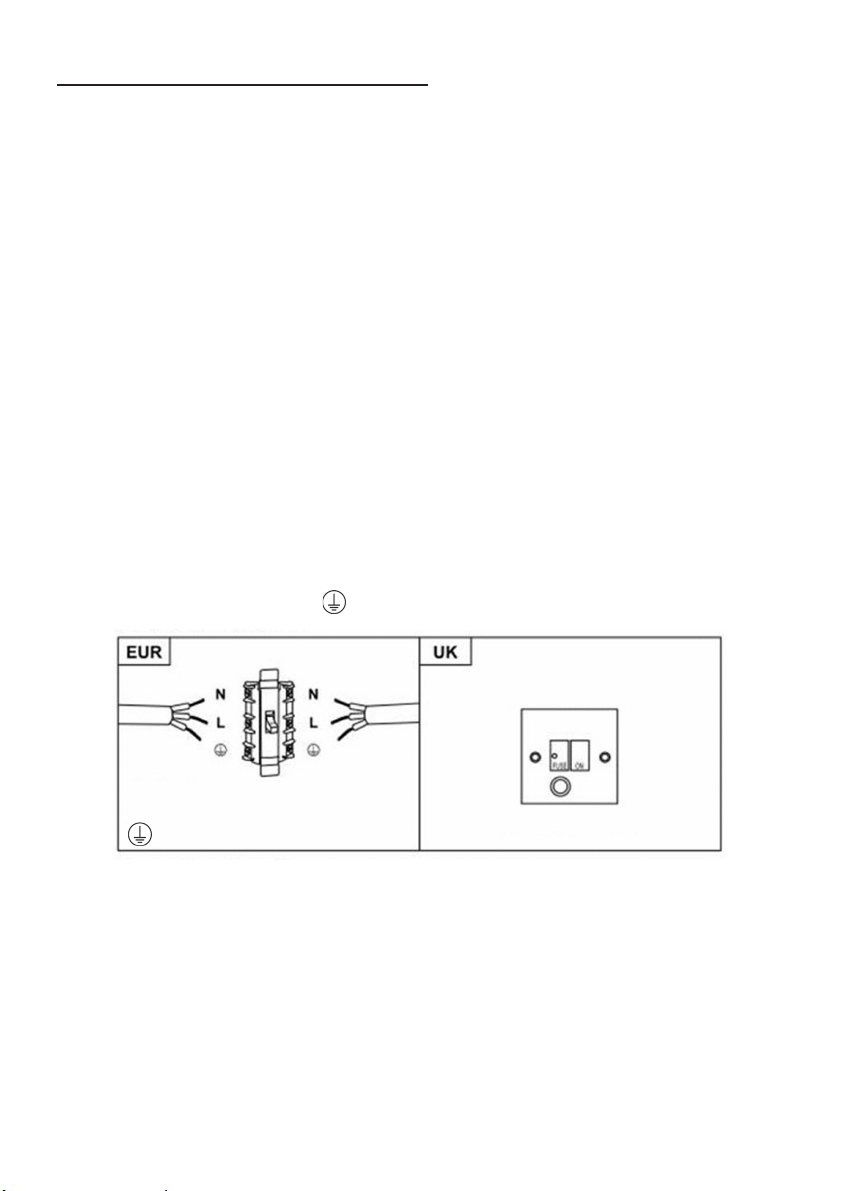
ELEKTRISCHE EINRICHTUNG
N (Blau)
L
EINE 3-AMPERE-SICHERUNG
VERWENDEN
2-POLIGER NETZANSCHLUSS
Alle Installationen müssen von einer kompetenten Person oder einem qualifizierten
Elektriker durchgeführt werden. Stellen Sie vor dem Anschluss des Netzteils sicher,
dass die Netzspannung der Spannung auf dem Typenschild entspricht.
Direkte Verbindung
Das Gerät muss mit einem allpoligen Trennschalter mit einer Mindestöffnung
von 3 mm zwischen den Kontakten direkt an das Netz angeschlossen werden.
Der Installateur muss sicherstellen, dass die korrekte elektrische Verbindung
hergestellt wurde und dem Schaltplan entspricht.
Das Kabel darf weder geknickt noch gequetscht werden.
Überprüfen Sie regelmäßig den Netzstecker und das Netzkabel auf
Beschädigungen. Ein beschädigtes Netzkabel darf nur durch ein Spezialkabel
ausgetauscht werden, das entweder beim Händler oder bei seinem technischen
Kundendienst erhältlich ist.
WARNUNG: Dies ist ein Gerät der Klasse I und MUSS geerdet werden.
Dieses Gerät wird mit einem 3-adrigen Netzkabel geliefert, das wie folgt gefärbt ist:
Braun = L oder Live (spannungsführend)
Blau = N oder Neutral
Grün und Gelb = E oder Erde
(Braun)
(Grün/Gelb)
Die Sicherung muss für 3 Ampere ausgelegt sein.
MIT SCHALTER UND SICHERUNG
85
Page 86
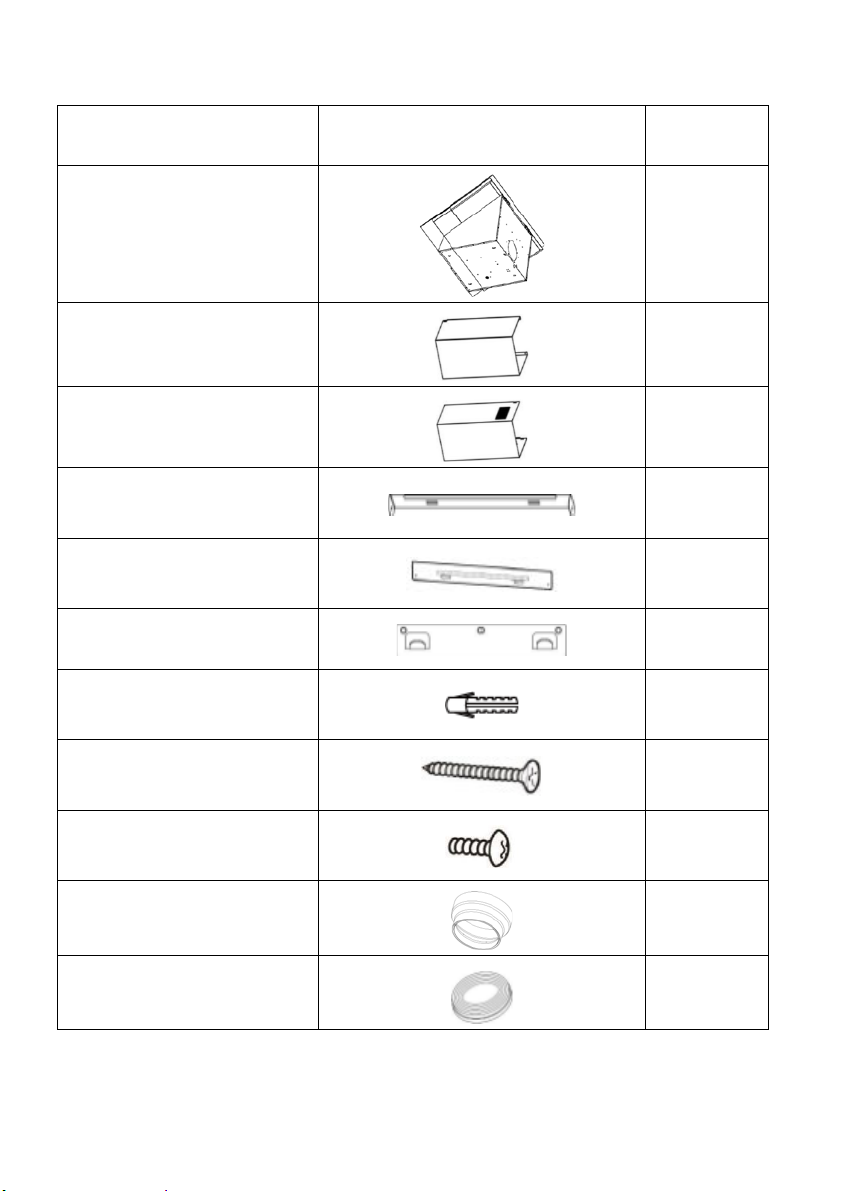
Liste der Standard-Installationszubehörteile
Obere
Abzugshalterung
Untere
Abzugshalterung
8 Dübel
Ø 8× Ø 6 weiß
Schraube
(ST4 * 30 mm)
Schraube
(ST4 * 8 mm)
Teil Darstellung Menge
Dunstabzugsgehäuse
Unterer Abzug
(500 mm)
Oberer Abzug
(500 mm)
Dunstabzugshalterung
Ø
1
1
1
1
1
1
9
9
Luftauslass
Aktivkohlefilter
6
1
2
86
Page 87
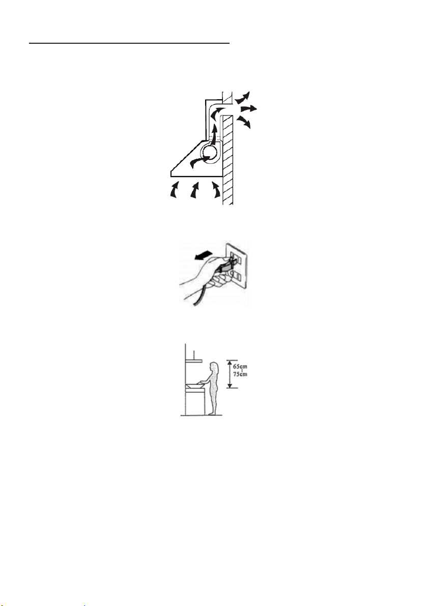
INSTALLATION (Wandmontage)
Wenn Sie einen Auslass nach außen haben, kann Ihre Abzugshaube wie unten
abgebildet über einen Absaugkanal (Emaille, Aluminium, Flexrohr oder feuerfestes
Material mit einem Innendurchmesser von 150 mm) angeschlossen werden.
1. Schalten Sie das Gerät vor der Installation aus und ziehen Sie den Stecker
aus der Steckdose.
2. Um eine optimale Wirkung zu erzielen, sollte die Abzugshaube in einem
Abstand von 65~75 cm von der Kochstelle montiert werden.
87
Page 88
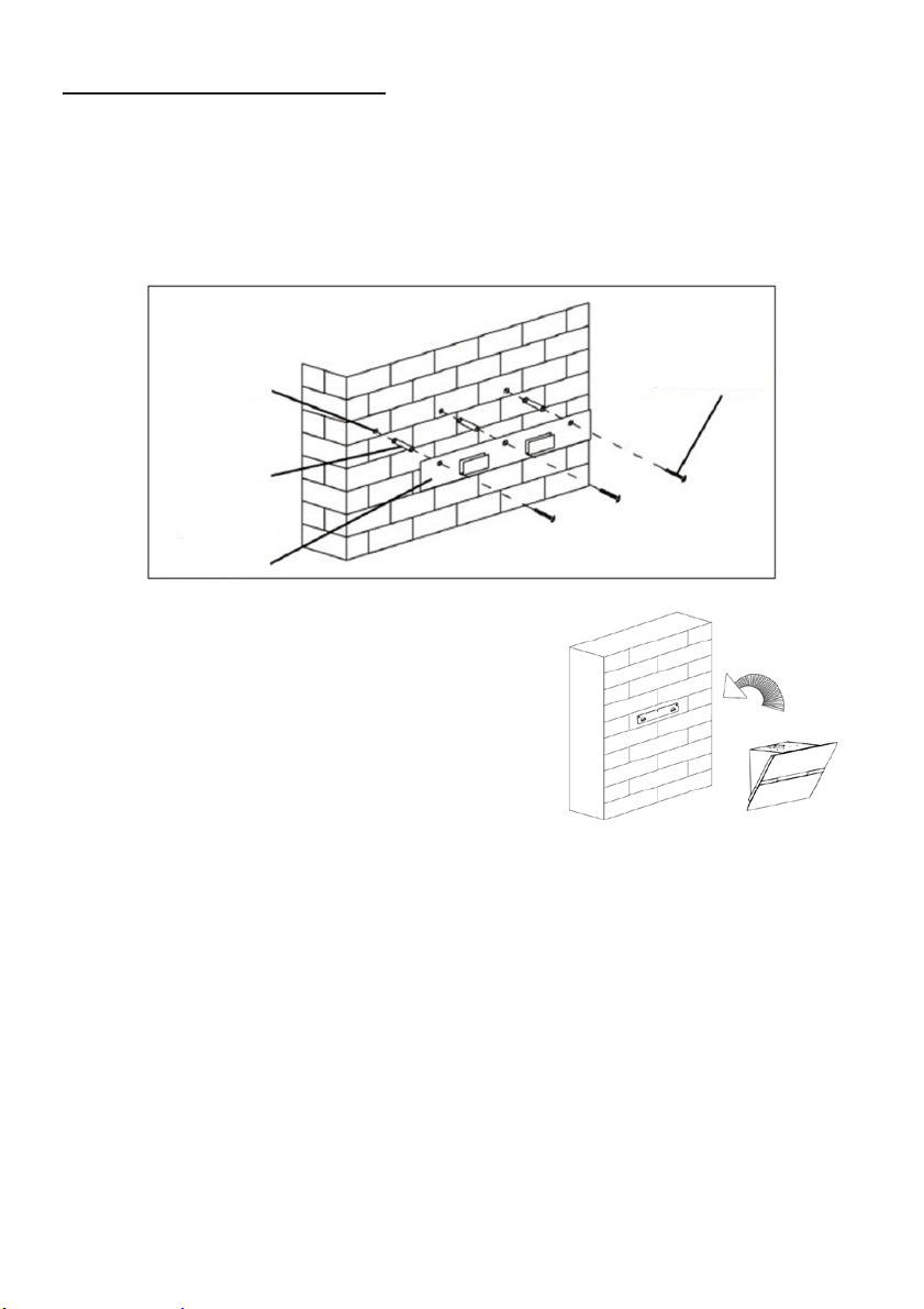
MONTAGE DER HAUBE
Löcher an
Wand
Dübel
Dunstabzugshalterung
Schraube
Positionieren Sie die Haube in der gewünschten Höhe unter Einhaltung der
Mindesthöhe über dem Kochfeld.
Markieren Sie die Position der Wandhalterung. (Setzen Sie die Löcher zwischen
700 und 800 mm über der Arbeitsplatte.) Entfernen Sie die Haube und positionieren
Sie die Wandhalterung, um die Lage der Löcher an der Wand zu markieren.
Bohren Sie die 3 Löcher in die Wand, um das entsprechende Befestigungssystem
anzubringen (Schraube ST4x30 mm).
(4 mm x 30 mm)
der
Hängen Sie die Haube in die Nuten der
Wandhalterung.
88
Page 89
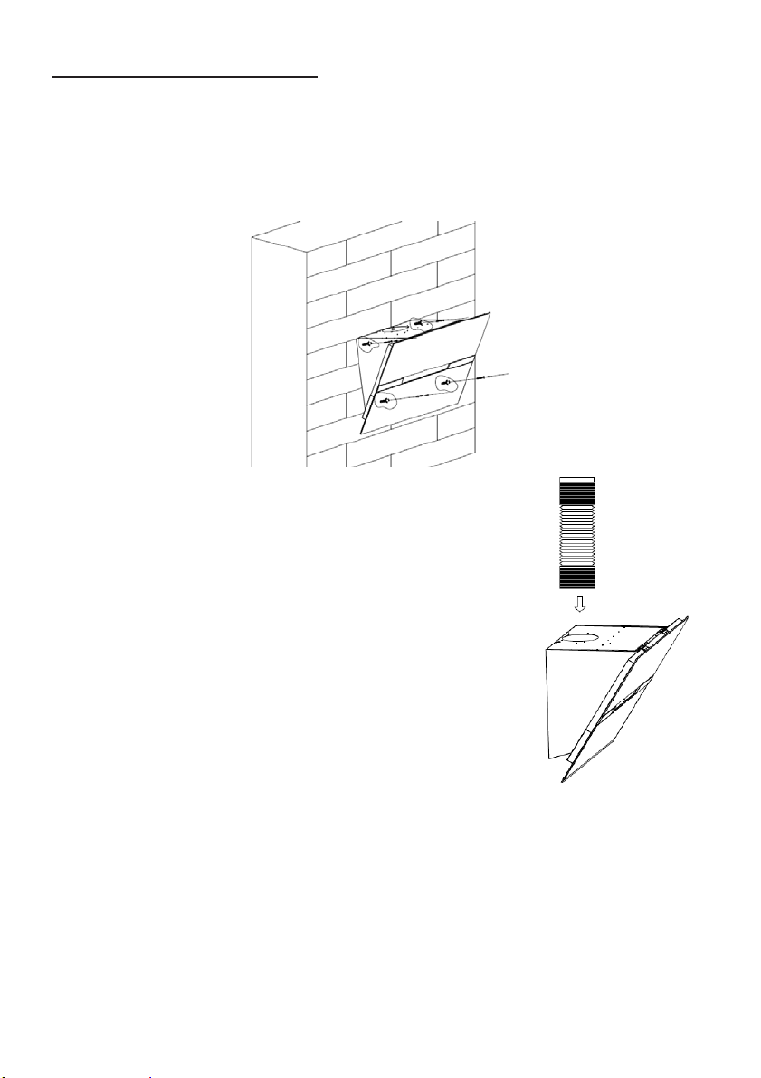
MONTAGE DER HAUBE
Wenn die Haube an ihrem Platz ist, legen Sie die Lage der 4 zusätzlichen
Wandbefestigungsschrauben fest, wie in der folgenden Abbildung gezeigt.
Entfernen Sie die Haube, um die Löcher in die Wand zu bohren, und setzen Sie
die Dübel ein.
Befestigen Sie das Haubengehäuse mit 4 Schrauben und den 4-mm-Dübeln an
der Wand.
Zur Benutzung der Absaugfunktion bringen Sie den
Abluftkanal wie gezeigt am Luftauslass an.
89
Page 90

MONTAGE DER HAUBE
Oberer Abzug (innen)
Untere
Abzugshalterung
Unterer Abzug (außen)
Befestigen Sie die untere Abzugshalterung wie abgebildet am unteren Abzug.
Verwenden Sie 2 Schrauben St4x8 mm.
(Schrauben nicht zu fest anziehen; der obere Abzug sollte leicht in den unteren
Abzug gleiten können)
Setzen Sie den oberen Abzug in den unteren Abzug ein.
Positionieren Sie den unteren Abzug im Gerät und markieren Sie dann die Löcher
an der Wand.
Entfernen Sie den unteren Abzug und bohren Sie dann Löcher in die Wand: Loch
für Schraubendurchmesser Ø 8 mm.
Benutzen Sie für Ihre Wand geeignete Dübel.
90
Page 91
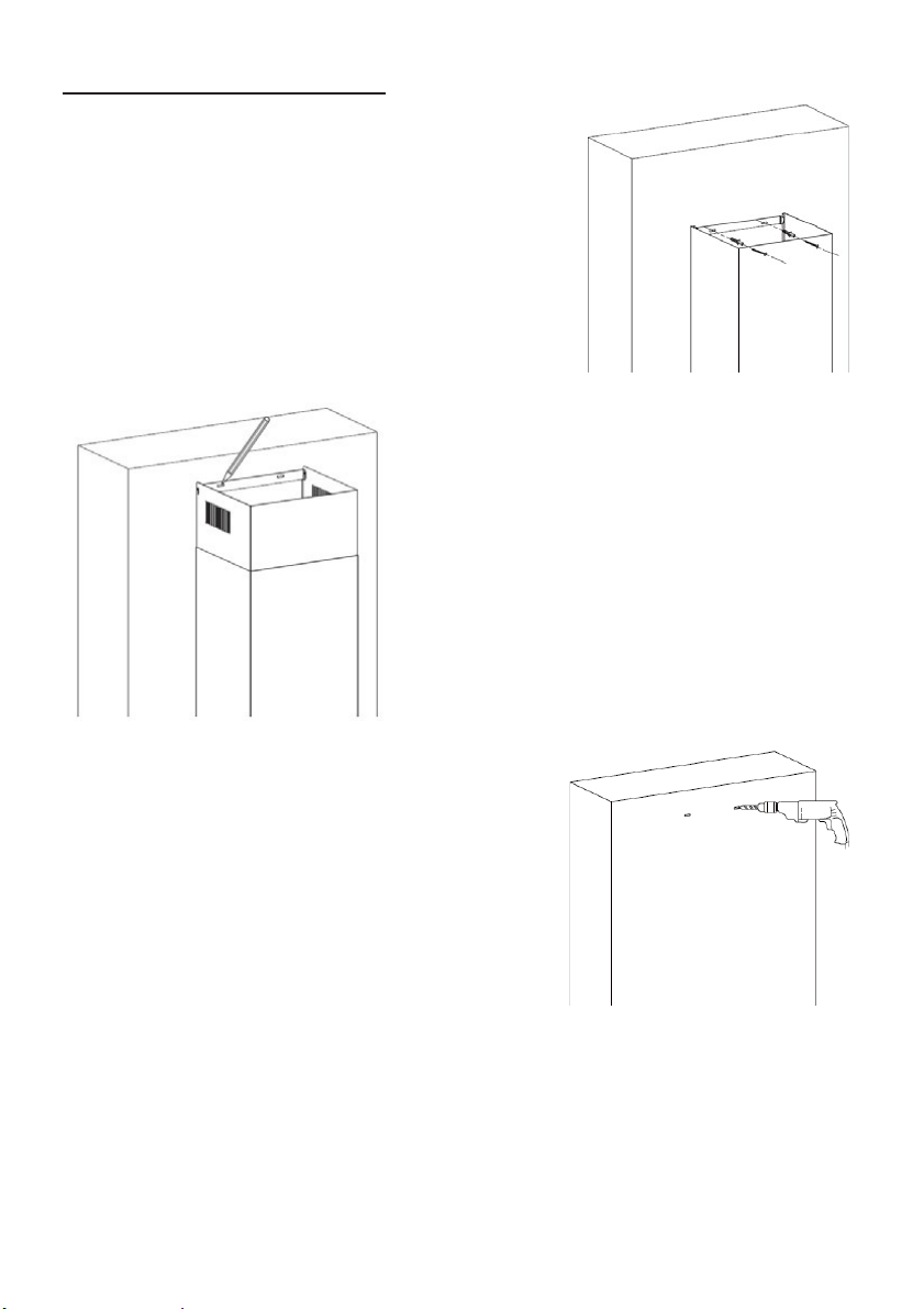
MONTAGE DER HAUBE
Installieren Sie den unteren Abzug, indem Sie ihn
mit 2 Schrauben mit einem Durchmesser von
Ø 8 mm an der Wand anbringen.
Ziehen Sie dann den oberen Abzug auf die
gewünschte Höhe nach oben. Markieren Sie
die Positionen der Montagelöcher der
oberen Abzugshalterung.
Senken Sie den oberen Abzug ab, und bohren
Sie dann Löcher in die Wand.
Setzen Sie die Dübel ein.
91
Page 92

MONTAGE DER HAUBE
Schraube
Befestigen Sie die Wandhalterung des oberen
Abzugs mit den gewählten Dübeln (8-mmSchrauben empfohlen) an der Wand.
Montieren Sie den oberen Abzug
wieder und befestigen Sie ihn mit
2 Schrauben ST4x8 mm an der
Wandhalterung
Befestigen Sie den unteren Abzug mit
2 Schrauben ST4x8mm an den Laschen
der Dunstabzugshaube.
92
Page 93

Liste der Standard-Installationszubehörteile
Teil Darstellung Menge
Luftleitblech
Halterung
Ø8 Dübel Ø8×Ø6 weiß
Schrauben ST4.0×30
Schrauben ST3.5×12
1
1
2
2
2
93
Page 94

INSTALLATION (LUFTFÜHRUNG FÜR T-FORM,
GEWÖLBTES GLAS, FLACHGLASMODELLE)
Die Luftführung ist im Lieferumfang enthalten und nicht optional.
1. Befestigen Sie die Halterung am T-förmigen Kunststoffauslass mit 2
ST3,5x12mm-Schrauben, wie unten gezeigt:
2. Bohren Sie 2 Löcher für die Dübel in die Wand. Befestigen Sie die Halterung
mit den 2 mitgelieferten ST4x30mm-Schrauben an der Wand fest.
94
Page 95

3. Befestigen Sie das Abluftrohr wie unten gezeigt am Luftauslass der
Dunstabzugshaube:
4. Bringen Sie den Abzug am Gerät an.
• Bitte beachten Sie: T-förmiger Kunststoffauslass und V-Klappen können nicht
gleichzeitig verwendet werden. Sie können sie auf zwei Arten verwenden: 1.
V-Klappe zum vorhandenen Auslass hinzufügen; 2. T-förmigen
Kunststoffauslass verwenden, keine V-Klappe hinzufügen.
• Hinweis: Das Produkt ist mit V-Klappen-Zubehör ausgestattet. Dieses Zubehör
ist für die Installation, den Betrieb und die Verwendung des Produkts nicht
zwingend erforderlich.
95
Page 96
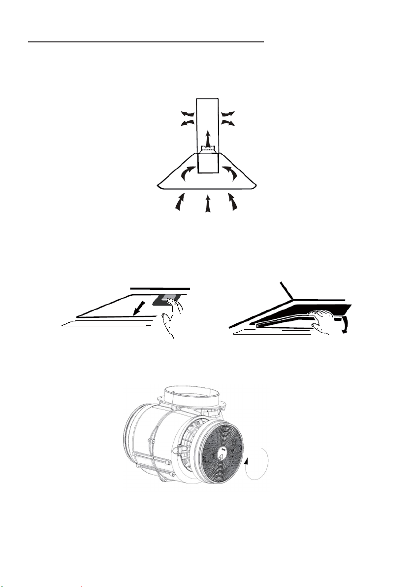
INSTALLATION (ENTLÜFTUNG INNEN)
Schließen
Wenn Sie keinen Auslass nach außen haben, ist kein Abluftrohr erforderlich. Die
Installation entspricht der im Abschnitt „INSTALLATION (ENTLÜFTUNG
AUSSEN)“ beschriebenen Vorgehensweise.
Ein Aktivkohlefilter kann zur Geruchsbindung eingesetzt werden.
Um den Aktivkohlefilter zu installieren, sollte zuerst der Fettfilter entfernt werden.
Drücken Sie auf die Verriegelung und ziehen Sie sie nach unten.
Setzen Sie den Aktivkohlefilter in das Gerät ein und drehen Sie ihn im
Uhrzeigersinn. Wiederholen Sie diesen Vorgang auf der anderen Seite.
HINWEIS:
o Vergewissern Sie sich, dass der Filter sicher verriegelt ist. Andernfalls könnte
er sich lösen und zu einer Gefahr werden.
o Bei angeschlossenem Aktivkohlefilter wird die Saugleistung reduziert
96
Page 97
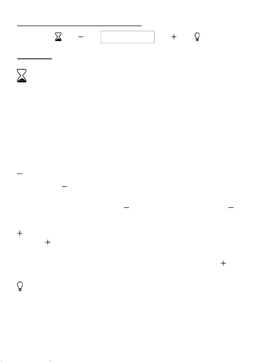
BESCHREIBUNG DER BAUTEILE
BETRIEB
Timer-Taste
1. Einstellen der Uhrzeit
Wenn sich die Motorhaube im Standby-Modus befindet (Motor funktioniert
nicht), drücken Sie die Timer-Taste, um die Zeiteinstellung aufzurufen.
Drücken Sie die Taste „Lüftergeschwindigkeit“, um die Tageszeit
einzustellen, und drücken Sie die Taste „Licht“, um die Minute einzustellen.
2. Timer einstellen
Wenn sich die Motorhaube im Betriebsmodus befindet, drücken Sie die
Timer-Taste, um den Countdown-Zähler einzustellen.
Wenn Sie die Timer-Taste einmal drücken, erhöht sich der CountdownZähler um eine Minute. Der maximale Countdown-Zeit beträgt 60 Minuten.
Taste zur Leistungsverringerung
Die Taste hat eine Hintergrundbeleuchtung und dient dazu, die Drehzahl
des Lüfters zu erhöhen oder den Lüfter auszuschalten. Wenn Sie die Taste
bei Stufe 3 drücken und die Beleuchtung an ist, verringert sich die
Lüfterleistung durch Drücken der Taste wie folgt: 3-2-1. Wenn Sie die
Taste bei Stufe 1 drücken, befindet sich der Lüfter im Standby-Modus und
die Hintergrundbeleuchtung wird ausgeschaltet.
Taste zur Leistungserhöhung
Die hat eine Hintergrundbeleuchtung und dient dazu, den Lüfter
einzuschalten oder die Lüfterleistung zu erhöhen. Wenn Sie die Taste im
Standby-Modus lange drücken, wird die Hintergrundbeleuchtung
eingeschaltet, und der Lüfter läuft mit geringer Leistung. Drücken der
Taste, erhöht sich die Lüfterleistung wie folgt: 1-2-3.
Beleuchtungstaste
Hiermit schalten Sie die Beleuchtung EIN und AUS.
97
Page 98
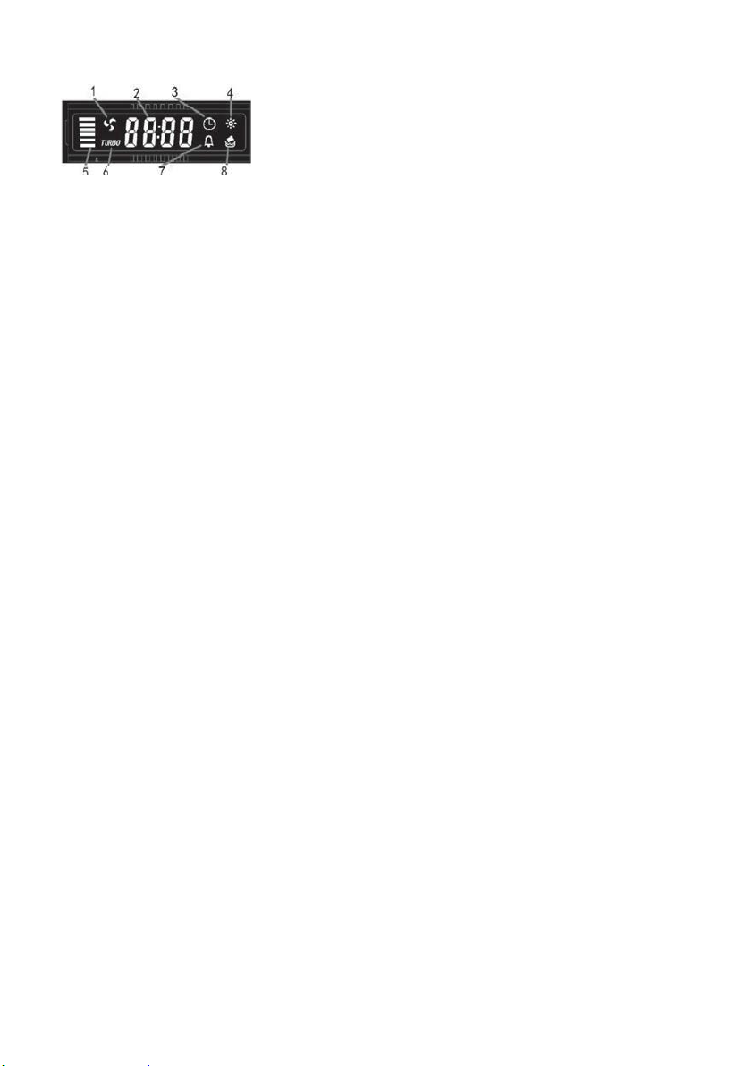
LCD-Display
1. Motorsymbol; dreht sich, wenn der Motor läuft
Erstinbetriebnahme
2. Zeitanzeige
3. Timer-Symbol; erscheint, wenn Timer eingestellt
ist und läuft
4. Licht-Symbol
5. Motorleistung
6. Turbo-Symbol; erscheint, wenn die maximale
Leistung eingestellt ist
7. Alarm-Symbol; erscheint für 5 Sekunden, wenn
der Timer-Countdown abgelaufen ist
8. Reinigungsalarm; erscheint nach einer
Betriebsdauer von 14 Stunden oder bei der
98
Page 99
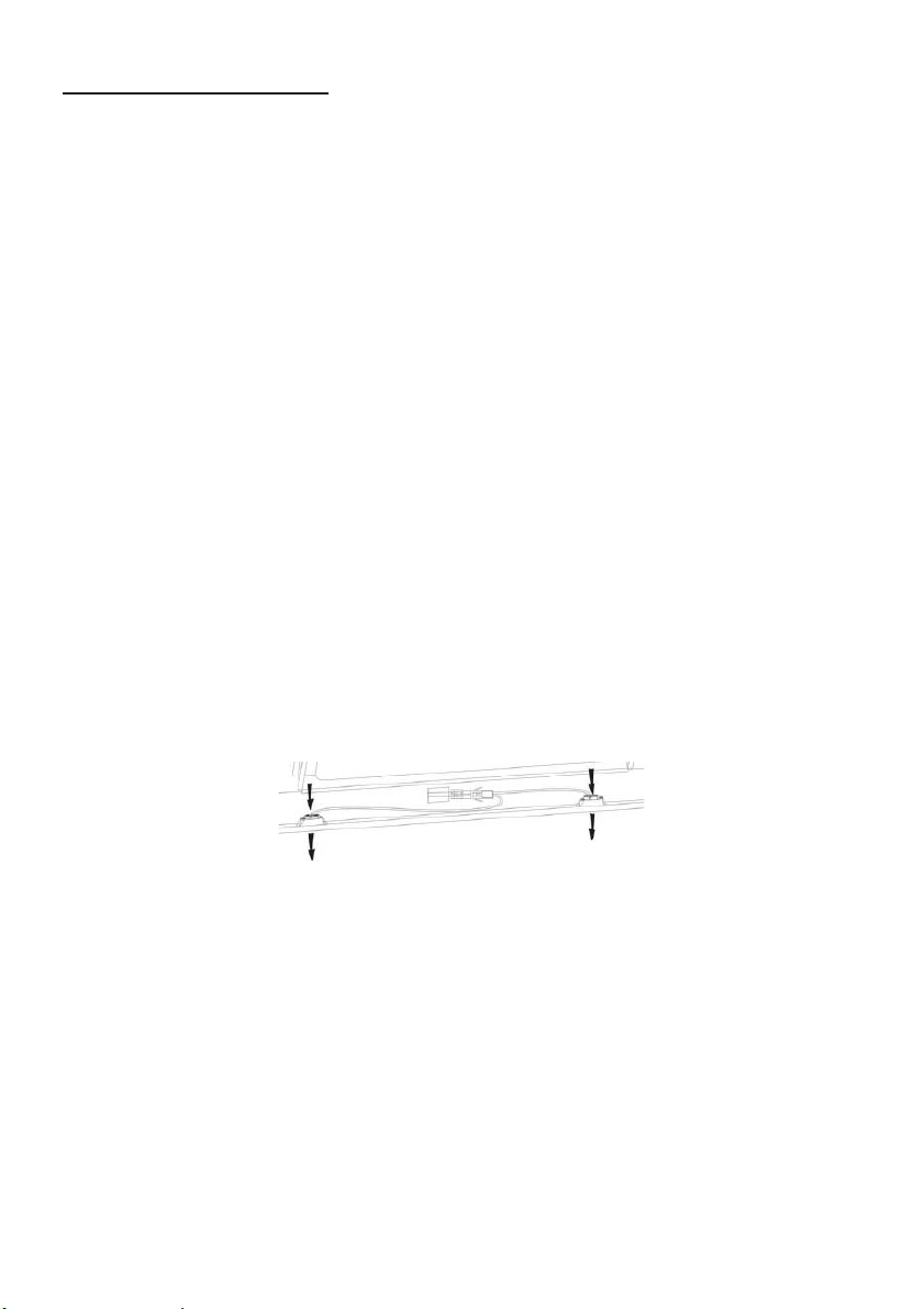
INSTANDHALTUNG
Schalten Sie vor dem Reinigen das Gerät aus und ziehen Sie den Netzstecker.
I. Regelmäßige Reinigung
Verwenden Sie ein weiches Tuch, das mit handwarmem, mildem Seifenwasser
oder Haushaltsreiniger befeuchtet ist. Verwenden Sie zur Reinigung des Geräts
niemals Metallpads, Chemikalien, scheuerndes Material oder harte Bürsten.
II. Monatliche Reinigung des Fettfilters
WICHTIG: Reinigen Sie den Filter jeden Monat, um eine Brandgefahr zu
vermeiden.
Im Filter sammeln sich Fett, Rauch und Staub... . somit hat der Filter direkten
Einfluss auf die Effizienz der Dunstabzugshaube. Wird der Filter nicht gereinigt,
lagern sich die (potenziell brennbaren) Fettrückstände im Filter ab. Reinigen Sie
den Filter mit einem Haushaltsreiniger.
III. Jährliche Reinigung des Aktivkohlefilters
Dies gilt ausschließlich für Geräte, die im Umluftmodus betrieben werden (keine
Abluft nach außen). Der Aktivkohlefilter fängt Gerüche ab und muss mindestens
einmal im Jahr ausgetauscht werden,
je nachdem, wie häufig die Dunstabzugshaube verwendet wird.
IV. Auswechseln des Leuchtmittels
Lösen Sie die Schrauben der Glasabdeckung und entfernen Sie diese.
Machen Sie die auszutauschende Glühbirne ausfindig, die sich im
Lampensockel im freiliegenden Teil der Abdeckung befindet.
Trennen Sie die Verkabelung und entfernen Sie den Lampensockel und
die Verdrahtung von der Abdeckung. Wichtig! Es ist nicht möglich, die
Glühbirnen einzeln auszutauschen. Die Glühbirnen, die Lampenfassungen
und die Verkabelung müssen als komplettes Bauteil ausgetauscht werden.
(LED-Licht: MAX 1,5 W)
Montieren Sie die Ersatzlampen, Lampenfassungen und Kabel
entsprechend des Original-Bauteils. Schließen Sie anschließend die
Verdrahtung erneut an.
Setzen Sie die Glashaube wieder auf, und ziehen Sie die Glasschrauben an.
Vergewissern Sie sich, dass die Schrauben vollständig angezogen sind.
99
Page 100

FEHLERBEHEBUNG
Störung
Ursache
Lösung
Die Leuchte geht
an, aber das
Gebläse läuft
Der Gebläseflügel ist
blockiert.
reparieren.
Der Motor ist defekt.
Sowohl Licht als
ist durchgebrannt.
Ersetzen Sie die Glühbirne durch
Das Netzkabel löst sich.
Stecken Sie das Netzkabel wieder
ein.
Starke
Der Gebläseflügel ist
Schalten Sie das Gerät aus und
reparieren.
Der Gebläsemotor ist
Schalten Sie das Gerät aus und
reparieren.
Nehmen Sie das Gerät ab und
befindet.
Die Saugleistung
ausreichend
Zu großer Abstand
Kochfeld
Passen Sie den Abstand auf 65-
nicht
Schalten Sie das Gerät aus und
lassen Sie es ausschließlich durch
qualifiziertes Servicepersonal
auch Gebläse
funktionieren
nicht.
Vibrationen des
Gerätes
ist nicht
Die Halogen-Glühbirne
beschädigt.
nicht korrekt befestigt.
Das Gerät ist nicht
ordnungsgemäß an der
Halterung aufgehängt.
zwischen Gerät und
eine mit entsprechender Leistung.
lassen Sie es ausschließlich durch
qualifiziertes Servicepersonal
lassen Sie es ausschließlich durch
qualifiziertes Servicepersonal
überprüfen Sie, ob sich die
Halterung an der richtigen Stelle
75 cm an.
KUNDENDIENST
Wenn Sie die Ursache der Betriebsstörung nicht feststellen können, schalten Sie
das Gerät aus und wenden Sie sich an den Kundendienst.
SERIENNUMMER DES PRODUKTS. Wo befindet sich die Seriennummer?
Es ist wichtig, dass Sie dem Kundendienst Ihren Produktcode und seine
Seriennummer (ein 16-stelliger Code, der mit der Nummer 3 beginnt) mitteilen;
diese finden Sie auf dem Garantiezertifikat oder auf dem Typenschild am Gerät.
Dies trägt dazu bei, unnötige Anfahrten für Techniker und damit (und
insbesondere) anfallende Kosten zu vermeiden.
100
 Loading...