

Page 1

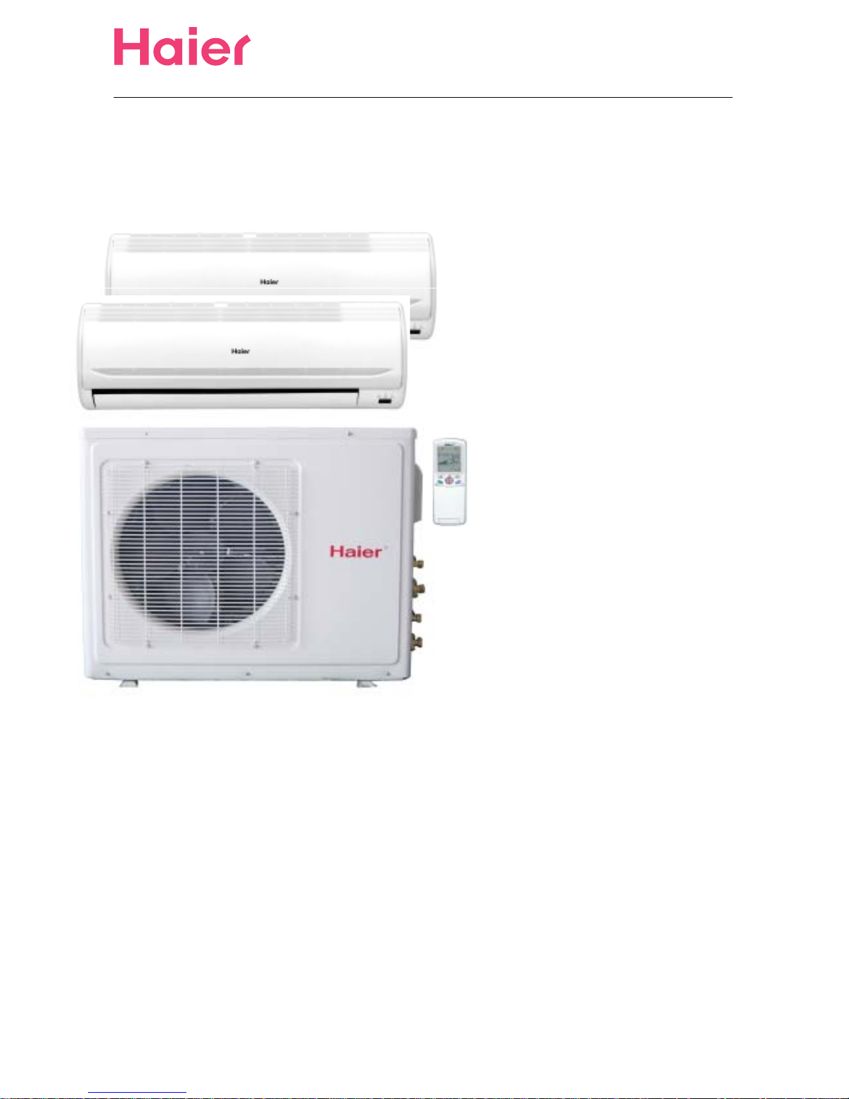
SERVICE MANUAL
Air Conditioners
CAUTION
READ THIS MANUAL CAREFULLY TO
DIAGNOSE TROUBLE CORRECTLY
BEFORE OFFERING SERVICE .
MODEL: H2SM-(9+12)H03/R2
THIS MANUAL IS USED BY
QUALIFIED APPLIANCE
TECHNICIANS ONLY. HAIER
DOES NOT ASSUME ANY
RESPONSIBILITY FOR PROPERTY
DAMAGE OR PERSONAL INJURY
FOR IMPROPER SERVICE
PROCEDURES DONE BY ONE
UNQUALIFIED PERSON.
Air Conditioner
Edition:2006/1/10
Page 2
Air Conditioner
Edition:2006/1/10
IMPORTANT INFORMATION
ƽҏFeatures
ƽҏComfortable: wide-angle airflow
ƽhealth air purifying
ƽquiet operation
ƽҏsuper energy efficient
ƽMain Specification
ƽCooling CapacityΚ 2900/3300/5800W
ƽRated Power/Current(cooling)Κ960/1020/2050W/4.6/4.8/9.0A
ƽEER: 3.02/3.23/2.82W/W
ƽHeating CapacityΚ 2800/3300/6000W
ƽRated Power/Current(heating): 900/980/1760W/4.5/4.6/8.0A
ƽCOP: 3.11/3.36/3.4
ƽAir Volume(Indoor): 400/500m
3
/h
ƽPower: 1PH 220-230V~ 50 Hz
MODEL: H2SM-(9+12)H03/R2
Page 3
Air Conditioner
Edition:2006/1/10
Safety Information
General Information
This Service Manual describes the operation,disassembly,troubleshooting,and repair of Haier Room Air
Conditioners,etc. It is intended for use by authorized servicers who troubleshoot and repair these units.
NOTE:It is assumed that users of this manual are familiar with the use of tools and e quipment used to
troubleshoot and repair electrical,mechanical,and refrigeration systems;and understand the terminology
used to describe and discuss them.
Haier urges you read and follow all safety precautions and warnings contained in this manual. Failure
to comply with safety information may result in severe personal injury or death.
Related Publications
This is a base service manual,covering a range of similar models.It is intended to be used in
conjunction with the Parts Manual and Technical Sheet c overing s pecific model being serviced.
General Precautions and Warnings
WARNING
To avoid risk of personal injury or death due to electrical shock,disconnect electrical power to unit
before attempting to service the unit.
WARNING
To avoid risk of personal injury or death due to electrical shock,DO NOT,under any circumstances,alter
the grounding plug .Air conditioner must be grounded at all times.Do not remove warning tag from power
cord.If a two-prong (non-grounding) wall receptacle is encountered,contact a qualified electrician and
have the receptacle replaced with a properly grounder wall receptacle in accordance with the National
Electrical Code.
WARNING
To avoid risk of personal injury or death due to electrical shock,grounding wires and wires colored like
groundi ng wires are NOT to be used as current carrying conductors.The standard accepted color coding
for ground wires is green or green with a yellow stripe.Electrical components such as the compressor
and fan motor are grounded through an individual wire attached to the electrical component and to
another part of the air conditioner.Groundi ng wires should not to be removed from individual components
while servicing,unless the component is to be removed and replaced.It is extremely important to replace
all removed grounding wires before completing service.
WARNING
To avoid risk of heat exposure,which may cause death or severe illness,air conditioner must be
monitored when malf unctions or shuts down.
Page 4

CONTENTS
1. SPECIFICATION....................................1
2. ELECTRICAL CONTROL..............................3
3
. TROUBLE SHOOTING.................................27
4
. INSTALLA TION....................................32
5
. CIRCUIT AND WIRING DIAGRAM.......................42
Air Conditioner
Edition:2006/1/10
Page 5

Air Conditioner
Edition:2006/1/10
SPECIFICATION
1
Page 6
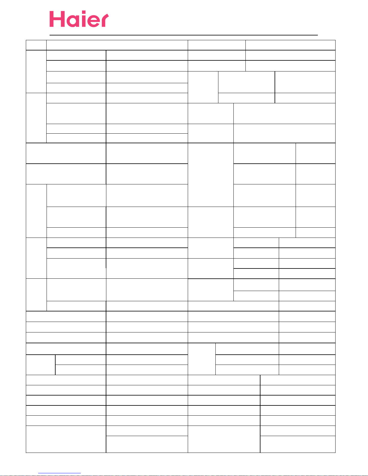
Model˖
H2SM-(9+12)H03/R2
Brand Mark˖
-----
Cooling Capacity˖
2900/3300/5800W
Frequency Range˖
50Hz
Rated Power/Current˖
960/1020/2050W/9.0A
Power
1PH 220-230V~ 50 Hz
Max Power/Current˖
2400W/12.4A
Cooling
EE
R 3.02/3.23/2.82W/W
Model×Sectional Area˖
--------
Heating Capacity˖
2800/3300/6000W
Power Cord
Refer. No.˖ --------
Rated Power/Current˖
900/980/1760W/8.0A
Compressor
manufacturer/Type
Max Power/Current˖ 2520W/
13.0A
Heating
COP 3.11/3.36/3.40
Compressor
Oilcharge
Power/Current of
Electric Heating˖
----- Type/NetCharge˖
R410A
Operating temp. range -7OC-43OC
Additional Charge for
exhausting air.
0g
H˖
1180 r/min
Refrigerant
Charge if over Standrad
Pipe Lenth
50g/m
M˖
1050 r/min
Lenth×Internal/External
Diametre
2.7*1.4
Indoor
Velocity
L˖
920 r/min
Capilary
Refer No.˖
H˖ 840 r/min Indoor˖ 1.30 mm
H˖ ---- r/min
Height of rising
radiator slice
Outdoor˖ 1.37 mm
H˖ ---- r/minNet˖
8.8kg
Outdoor
Velocity
Indoor Weight
Gross˖
10.6kg
Net˖
57kg
Indoor˖ 500(12) m3/h
Outdoor Weight
Gross˖
66kg
Air
Vol ume
(High)
Outdoor˖ ----- m
3
/hIndoor Dimension(L×W×H)˖ 795×265×182 mm
Capacitor of Fan Motor˖
……
Indoor Packaging Dimension(L×W×H) 865x272x330 mm
Class of electric Shock Protection
ĉ
Outdoor Dimension (L×W×H)˖
810×288×680 mm
Class of Water Proof˖ IP 24 Outdoor Packaging dimension(L×W×H) 960×405×760 mm
Moisture Removal˖
2.4×10
-3m3
/h
liquid /Gas pipe Diametre
ij6.35/9.52 mm
Model
: YR-
H10 standard Lenth
5m
Remote
Controller Refer. No.˖
0010401628
Refrigerant
Pipe
Max Lenth 15 m
Remote Controller Bracket˖ ----- Lenth/Diametre of Drain Hose ----
Appearance˖ ----- Max. pressure at warm side˖ 4.15 MPa
Climate Type˖ T1 Max.pressure at cool side˖ 4.15MPa
Installation Bracket Type˖ ----- Plug Type(spec.)˖ ---
Area available for clooling/heating
15-23 m
2
Ammeter spec.˖ ---
Dry/Wet ball(indoor)˖ 32℃/ 223 ćDry/Wet ball(indoor):27 /ć --ć
Max.running
temperature(cooling):
Dry/Wet ball(outdoor)˖ 43 / 26 ćć
temperature(heating):
Dry/Wet ball(outdoor):24℃/18℃
Air Conditioner
Edition:2006/1/10
2
Page 7

Air Conditioner Edition:2005/11/18
ELECTRICAL CONTROL
Page 8
One. Temperature Control Function
In temperature control function, the operation frequency of outdoor unit is determined based on room
temperature and the set temperature.
In automatic fan speed mode, indoor fan is controlled based on the need of temperature control
In heating mode, indoor fan is controlled based on the temperature of coil.
1-1-1.Specification of Indoor Ambient Temperature Sensor
In case of short circuit or open circuit, indicator lamp alarms and indoor fan stops. When normal condition is resumed,
fan will automatically restart and operate normally.
Short Circuit:
Temperature: over 126
o
C, Hexadecimal System: over F8H, Resistance: below 0.65K,Voltage: over 4.85V.
Normal Temperature:
Temperature: 25
o
C, Hexadecimal System: 40H, Resistance: 23K, Voltage: 2.33V.
Open Circuit:
Temperature: below -31
o
C, Hexadecimal System: below 08H, Resistance: below 620K Voltage: below
0.15V.
B Parameter = 4200 R (25
o
C) = 23K
1-1-2 Specification of Indoor Coil Temperature Sensor
B Constant Number = 3700 R (25
o
C) = 10KΩ
1-1-3 When heating operation starts and indoor fan stops or when within 30s of indoor fan starts after
heating operation starts, the resistant of indoor ambient temperature sensor is ignored. (to avoid the
impact of heat exchanger temperature over it.)
When forced operation ends after start-up, temperature zone control begins.
1-2. Set Temperature Correction
Set temperature is corrected according to unit model, operation mode, fan speed and whether it is in
power operation.
Fan speed correction is available only during low and mid heating operation.
1-3. Temperature Zone Control
1-3-1.Error
Temperature zone error is calculated as per the following formula
:
In Heating Mode: E = (Remote Control Set Temperature + Correction Value) – Indoor Temperature
In Cooling & Dehumidification Mode: E = Indoor Temperature - (Remote Control Set Temperature +
Correction Value)
1-3-2 Compressor Shutdown
E is negative and |E|>∆T
Heating Cooling
∆T TCHAHL 0.67 TCHACL 0.33
After change of ∆T TCHAHH 0.67 TCHACH 1
∆T Change Condition When operation starts E ≥ 3.0℃,
Compressor shuts down after continuous testing for 120s,
At the beginning of operation, with reference to the conditions given in above table, it operates based
on the parameters after change of ∆T until compressor shuts down for the first time. In the time period
between compressor shutdown and restart, it operates based on ∆T. (except in dehumidification mode)
Compressor starts at the beginning of operation or upon switch of operation mode (except standby ends)
or when E (error) > -∆T.
When compressor is operating, remote control set temperature is changing towards the direction of
compressor shutdown and when it is below –∆T, compressor will shut down.
1-3-3. Compressor Operation
Compressor restarts when E (error) > -△T+0.67℃ and when 3 mins standby is over.
Air ConditionerEdition:2006/1/10
Page 9
T
wo. Indoor Fan Control
2-1. Heating
2-1-1. Warm Start
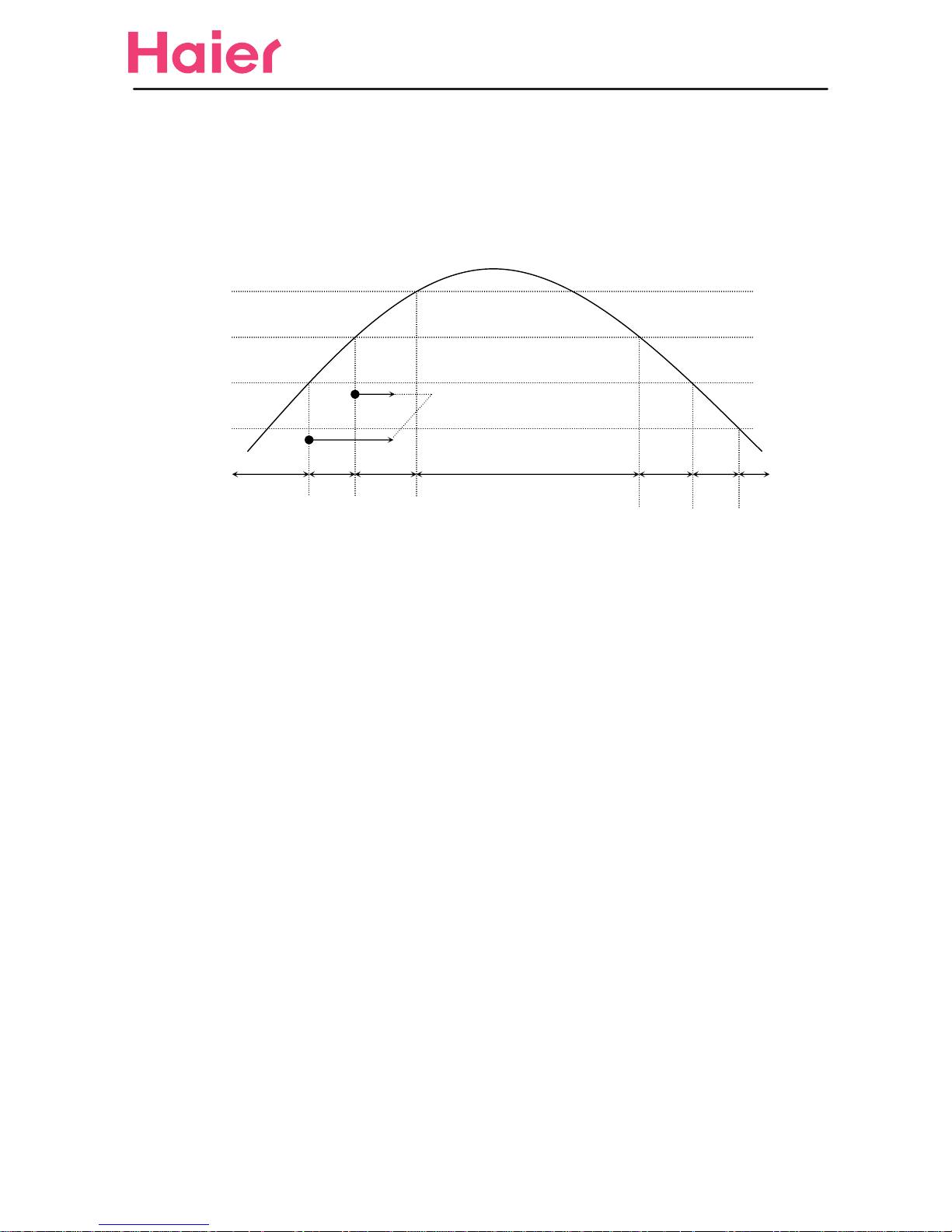
Cold Air Control in Heating Mode
Heat Exchange Temperature:
THHOT3
37.0℃
THHOT2
35.2℃
THHOT1
25.2℃ 4mins
THHOTR
16℃
Stop SLO LO Set LO SLO Stop
Conduct indoor fan control as per the above diagram and the heat exchange temperature.
1. Judge wind speed when heat exchange temperature is rising:
Fan is at super low level when heat exchange temperature is below 35.2℃.(Fan will stop upon
initially energized into heating mode or after defrosting, or when heat exchange temperature is lower
than 25.2℃. Fan is at super low level when temperature is higher than 25.2℃ but lower than
35.2℃.);
Fan is at low level when heat exchange temperature is between 35.2℃ and 37℃;
Fan will operate as per setting when heat exchange temperature is above 37℃.
2. Judge wind speed when heat exchange temperature is falling:
Fan is at low level when heat exchange temperature is below 35.2℃ but above 25.2℃;
Fan is at super low level and will maintain the mode when heat exchange temperature is lower than
25.2℃(Fan is at super low level upon initially energized into heating mode or after defrosting, or
heat exchange temperature is lower than 25.2℃ but higher than 16℃; Fan will stop when heat
exchange temperature falls below 16℃.)
3. Wind speed is at super low or low level when heat exchange temperature is rising. If heat exchange
temperature fails to enter the next temperature zone after 4 mins while wind speed rises to the next
stage, it is necessary to maintain the set wind speed for 4 mins before it is adjusted based on heat
exchange temperature.
4. When heat exchange temperature is falling, wind speed will return to set speed if low wind level is
maintained for over 4 mins.
2-1-2. 3 mins standby period when compressor shutdown.
1. When compressor shuts down(temperature sensor is off), airflow is low for the initial 20s then
reduced to super low (When in silent operation, it is SSLO);
2. Wind is maintained at super low level in the standby period in heating mode(Compressor stops during
mode switch.).
3. Remote control shut down and stop indoor fan.
2-1-3. Compressor Restart
When warm start, airflow is at remote control set level.
When in automatic airflow mode, airflow is determined based on temperature.
Refers to temperature zone control functions.
2-2 Cooling
Airflow is different when airflow is set at high, mid and low level.
When in automatic airflow mode, airflow is determined as per temperature. Refers to temperature control
functions. (Refers to 2-4-8)
2-3. Dehumidification
Air ConditionerEdition:2006/1/10
Page 10

2-3-1. Compressor is off and is in 3 mins standby.
Fan will stop if compressor stops
Fan is at super low level upon the end of 3 mins standby.
Compressor is on after 3 mins standby.
2-3-2. Compressor is on.
When airflow is set at high, mid or low level, fan will operate as per the setting.
When in automatic airflow mode, airflow is determined as per temperature.
Three. Air Refreshing
Up reception of remote control signal, negative ion generator will start operation to emit negative ion if
fan is operating.
If fan stops, negative ion generator is off.
When negative ion generator is off, if air-refreshing feature is set and fan restarts then negative ion
generator is on.
Four. Timed Operation
Time counting will start based on the difference of timer clock and current clock.
In timed operation, display panel timer lamp is on.
4-1. Timer Off
When timer off is set, panel timer lamp is on and unit will stop operation as per the timing.
4-2. Timer On
If timer on is set, when unit is off, panel timer lamp will be on and unit will resume operation as per the
timing and in set mode.
Execution sequence is based on the setting.
Five. Sleep Operation
When remote control set sleep mode, timer lamp is on.
5-1. In cooling/dehumidification mode, set temperature will rise 1
o
C after 1 hour operation and another
1
o
C after the second hour. The unit will stop after another 6 hours.
5-2. In heating mode, set temperature will fall 2
o
C after 1 hour and another 2 oC after the second hour
and will rise 1
o
C after another 3 hours and the unit will stop after another 3 hours.
5-3 If airflow of indoor fan is high before setting sleep mode, then it will turn into mid level after sleep
mode is set. If airflow of indoor fan is mid before setting, it will turn into low level after setting. If airflow of
indoor fan is low before setting, then it will not change after setting.
Six. Automatic Operation
Automatic operation consists of two features of automatic and full automatic, which can be realized
through EEPROM selection.
6-1. Automatic Operation Mode:
On entering this mode, main control unit will decide the corresponding operation mode as per room
temperature to maintain the set temperature(Set temperature is 23℃in heating mode and 26℃ in
cooling mode.).
Upon initial startup, the unit will enter heating mode if room inlet air temperature is equal to or lower
than 23℃ or it will enter cooling mode if temperature is higher than 23℃.
When entering heating mode, the unit will operate as per heating program(set temperature is 23℃)
Upon reaching temperature where compressor stops operation, compressor will stop and standby for 3
mins. In case it detects that inlet air temperature is higher than 27 15 mins after compressor stops, the ℃
unit will enter cooling mode. Otherwise, the unit will remain in heating mode.
When entering cooling mode, the unit will operate as per cooling program(set temperature is 26℃).
Temperature difference compensation is automatically cancelled. Upon reaching temperature where
compressor stops operation, compressor will stop and standby for 3 mins. In case it detects that inlet air
temperature is equal to or lower than 23℃ 15 mins after compressor stops, the unit will enter heating
mode. Otherwise, the unit will remain in cooling mode.
If the unit changes into automatic mode from any other mode and if the operation mode is changed
Air ConditionerEdition:2006/1/10
Page 11

(detect before operation), the unit will stop for 3 mins and it will operate based on inlet air temperature
after 3 mins.
Seven. Trial Operation
Trial operation will end after 30 mins, after which unit shuts down. In trial operation, the unit will quit trial
operation mode upon reception of signal.
Low load protection will not start.
Constant Frequency Multi-split Unit( Single, Double Compressors ) Low Load Protection
(Anti-freeze)Function:
Anti-freeze protection feature is available (Invalid in trial operation and heating mode):
Avoid freeze of indoor heat exchanger(in cooling and dehumidification mode)Compressor will stop
when temperature of indoor coil ≤ 0℃ and when compressor operates for over 5 mins. Compressor will
restart when temperature of indoor coil rises to over 7℃ (It must meet the needs of 3-min delay.).
In case high load protection is actuated twice within 30 mins, high load protection will alarm.
In case heat exchange temperature does not reach "THHEAT[2]", normal temperature zone control will
resume. .
Adopt the lower of either high load frequency or zone frequency as operation data.
Constant Frequency Multi-split Unit(single, double compressor)High Load Protection Control:
1. Fan Stop Protection: Indoor unit only sends A/D value to outdoor unit and outdoor unit exerts control;
2. Compressor Stop Protection:
Eight. Heating Low Temperature Treatment
In case it is unable to switch the four-way valve or in case the temperature of heat exchanger is below
"THHOTLTH"(-4.5℃)for "TMHOTLTH"(90s), compressor will stop and standby for 3 mins. Compressor
will restart when heat exchange temperature is above "THHOTLTH"(-4.5℃).
Fourteen. Communication
8-1 Communication between Indoor & Outdoor Unit
Note: This communication mode is compatible with three unit models of constant frequency
double-compressor multi-split, constant frequency single-compressor multi-split and inverter-controlled
multi-split.
8-1-1 Communication Sequence
Communication starts 2s after power is supplied. Indoor unit will send out signal first and transmission
will maintain at LO of 5ms then it starts to receive signal. In case, signal cannot be received within 2s,
another signal will be sent out. Upon reception of signal, another signal will be sent out after 10ms.
While indoor unit is waiting for signal input, its signal transmission is HI.
Error transmission occurs when indoor unit is unable to receive signal for 10 attempts (20s) after the
previous signal reception. In case of time reduction and shutdown, it is not considered as error
transmission.
Communication treatment will be engaged upon reception of correct HAD signal.
At the end of signal reception, communication data and reverse data will be compared and all the data
will be discarded in case of any error.
Outdoor unit will wait for signal from indoor HEADER HDR (81H) when power is supplied.
When sending signal, signal with header of C3H will be sent first.
During signal transmission, data"1" will output HI of 9MS and LO of 2MS, while data "0" outputs HI of
2MS and LO of 9MS.
Received signal is treated based on the majority of 5, 6 and 7MS.
Signal is only treated when correct HRD signal is received.
Nine. EEPROM Control
When outdoor unit is supplied with power, if there is any inconsistency between EEPROM parameter and
Air ConditionerEdition:2006/1/10
Page 12

checksum, EEPROM error.
When indoor unit receives EEPROM error signal from outdoor unit, it will display outdoor unit EEPROM error.
At this time, control and emergency operation are not acceptable.
It can only be cancelled through power off.
Ten. Error Record
There is no display when no error code record exists.
Error display mode automatically ends in 10s.
Only stop signal is accepted by remote control. Error record display mode ends corresponding to switch or
remote control stop signal.
For unit with EEPROM, record is saved when power is reset.
Eleven. Error Detect Method
1
1-1. Indoor Temperature Sensor Error
In operation, an error occurs if the temperature is above 126
o
C or below – 31oC.
Operation will resume automatically when temperature is outside the above range.
1
1-2. Heat Exchange Temperature Sensor Error
In operation, an error occurs if the temperature is above 196
o
C or below – 53oC.
Operation will resume automatically when temperature is outside the above range.
In error condition, low load protection is cancelled.
11-3. High Load
After high load and high limit is actuated, if the same operation recurs within 30 mins, a high load and high limit
error occurs.
11-4. Outdoor Temperature Sensor Error
On receiving error code of defrosting, air discharge temperature, base pane or outdoor temperature sensor,
indoor unit will display outdoor temperature sensor error.
Operation will resume automatically when receiving signal of removal of outdoor temperature sensor error.
In the error period, low load protection is cancelled.
1
1-5. Outdoor Unit Protection & Control Function
Indoor unit will display error when receives the following error codes:
Compressor Discharge Duct High Temperature Protection, DC Over Current, CT Disconnection, AC Over
Current, Power Module High Temperature Protection, Power Module Over Current Protection, Low Voltage
Protection, Outdoor Unit EEPROM Error, Compressor Operation Error.
Error conditions will be cancelled by stopping operation when outdoor unit receives 17654=0001,13=0 error
removal signal.
11-6. Transmission Error
Based on the condition of communication between indoor and outdoor unit, in case outdoor unit fails to
receive signal within 20s after indoor unit sends out signal, transmission is abnormal. (except in the period of
first 2 mins when power is supplied.). It is confirmed as transmission error when outdoor unit receive the error
signal.
Transmission error is removed by stopping operation.
Twelve. Special Function
1
2-1. Independent Operation of Indoor Unit
a. Entry Condition: First set remote control as heating high wind, 30
o
C, initial energization, press sleep key 6
times in 7s and there will be 6 sounds.
b. On entering independent operation of indoor unit, indoor unit will operate as per the following procedures:
Indoor unit will operate and communicate as per setting. Communication signal form outdoor unit will not be
treated by indoor unit while it will send signals to outdoor unit continuously.
c. Exit Condition: On receiving remote control or emergency shut down signal, it will exit independent
operation of indoor unit. Furthermore, it will exit independent operation of indoor unit after power off and power
on again. During independent operation of indoor unit, it may simulate outdoor unit and send the following
Air ConditionerEdition:2006/1/10
Page 13

signals to indoor unit:
1
2-2. Power-Off Compensation
a Entry Condition: Press sleep key 10 times in 7s and buzzer gives out 4 sounds and save the current status
into indoor unit EEPROM upon the entry.
b. On entering power-off compensation operation, indoor unit operates as per the following procedures:
Remote control emergency signal, and operates as per condition set by remote control and emergency setting
and save the current status into indoor unit EEPROM.
Main unit will operate as per condition set on panel board. And save the current status into indoor unit
EEPROM.
c. Exit Condition: Press sleep key 10 times in 7s and buzzer gives out 2 sounds
d. If timer and sleep features are set under power-off compensation condition, main unit memory is in a state
of shut-off if power is off and on again.
T
hirteen. Emergency Switch
When shutdown, press emergency switch down for less than 5s, the unit will start emergency operation.
When shutdown, press emergency switch down for more than 5s but less than 10s, the unit will start trial
operation.
When shutdown, press emergency switch down for more than 10s but less than 15s, it will demonstrate
the previous error.
When shutdown, press emergency switch down, the panel will display automatic operation.
When shutdown, press emergency switch down for less than 15s, or remove hand from emergency
switch, the unit will not accept remote control signal.
Unit enters shutdown condition after 15s.
Unit can receive remote control signal after 15s.
Press emergency switch during operation, air-conditioner will shut down.,
During operation, if error occurs, press emergency switch to shut down the unit to clear error condition.
During error presentation, press emergency switch and error presentation will end.
During operation, if emergency switch is pressed continuously (press and hold) in normal or abnormal
condition (such as tact switch short circuit) or in error presentation condition, the unit can also receive
remote control signal.
Error Record Presentation Mode:
When press and hold switch for 10s it gives out 3 sounds, release switch to enter error record
presentation mode. Press and hold switch for 15s, panel display is off and error record presentation
mode is cancelled.
Previous alarm information will be sent to display panel for status display.
Error record presentation mode is cleared after 10s. (Error record presentation mode is only displayed
for 10s.)
During the presentation, no remote control signal except shutdown signal is accepted.
There is no presentation when no error occurs, only buzzer utters sound.
Air ConditionerEdition:2006/1/10
Page 14
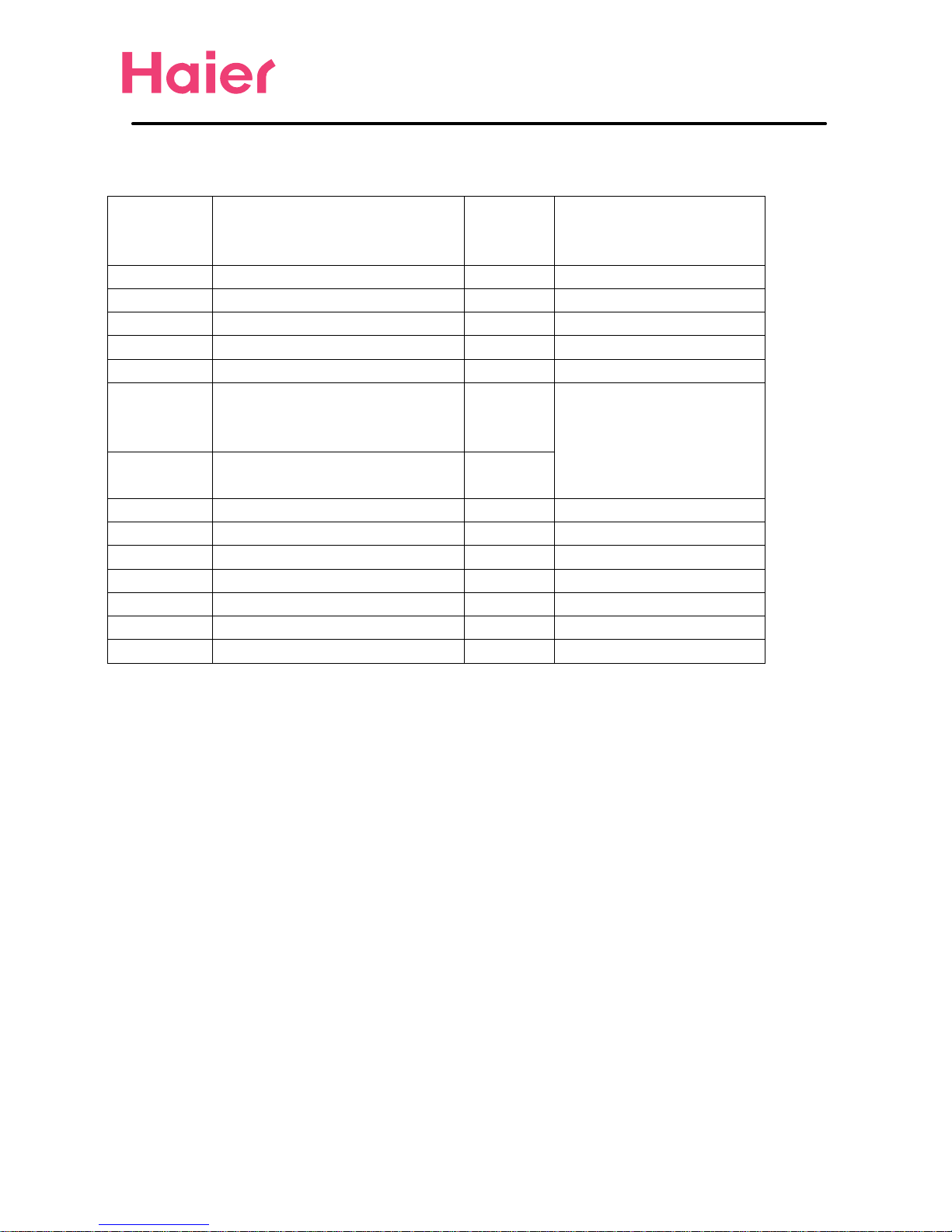
1. Definition of chip tubes’ pins
Chips are used in this manual and their pins are defined as follows:
Chip’s Pins Definition of Function Chip’s
Pins
Definition of Function
GND GND P37AIN5 CTA signal input
XIN XIN P36AIN4 CTB signal input
XOUT XOUT P35AIN3 tube temperature A
TEST GND P34AIN2 tube temperature B
VDD +5V P33 AIN1 Outdoor ambient temperature
P21 Alarm light
(to be connected with pull resistance)
reuse for self-checking/contracting
P32 AIN0
P22 Serial communication output
(to be connected with pull resistance)
P31
P32 P31 Model selection
0 0 Model 1
0 1 Model 2
1 0 Model 3
1 1 Model 4
RESET Reset P30 EEPROM--SCL
P20 4-way valve A P12 EEPROM--SDA
P00 4-way valve B P11 -INT1 Communication input A
P01 High air flowrate P10 -INTO Communication input B
P02 Mid air flowrate P07 Communication output A
P03 Low air flowrate P06 Communication output B
P04 Compressor B P05 Compressor A
2. Communication format
Note: This communication format is compatible with 3 models, i.e., double-compressor one-drive-two
without converter, single-compressor one-drive-two without converter and one-drive-two with
converter.
2.1. Sequence of communication
Communication begins 2 seconds after the power supply inputs. The indoor unit first gives out a
signal and outputs the LO which remains at 5 ms, then changes to receive signal. If it fails to
receive signal 2 seconds after the signal is given out, it will give out a signal once again. After the
signal is received, it will give out a signal once more 10 ms later. When the indoor unit is waiting
for the signal input, the signal output is HI. If the indoor unit fails to receive signals in normal
condition in times (20 seconds) after the previous signal has been received, the transmission is
abnormal. But time shortage and being halted are not of abnormal transmission. Communication is
carried out when a correct HDA signal is received. After the signal has been received, the
communication data is compared with the inverter data. When incorrect, all the data will be given
up. The outdoor unit waits to receive signal HEADER HDR(81H) from the indoor unit after the
power supply inputs. After the signal has been received, the communication data is compared with
the inverter data. When incorrect, all the data will be given up.
Air Conditioner
Edition:2006/1/10
Page 15
The outdoor unit waits to receive signal HEADER HDR(81H) from the indoor unit after the power
supply inputs. When transmitting signal, HEADER is C3H. When a signal is first transmitted at the
head, data "1" outputs HI of 9MS and LO of 2MS and data "0" outputs HI of 2MS and LO of 9MS.
When receiving signal, the signal reception is carried out depending on the majority of the 5th, 6th
and 7th 5,6,7MS.
The signal reception will not take place until a correct HDR signal is received.
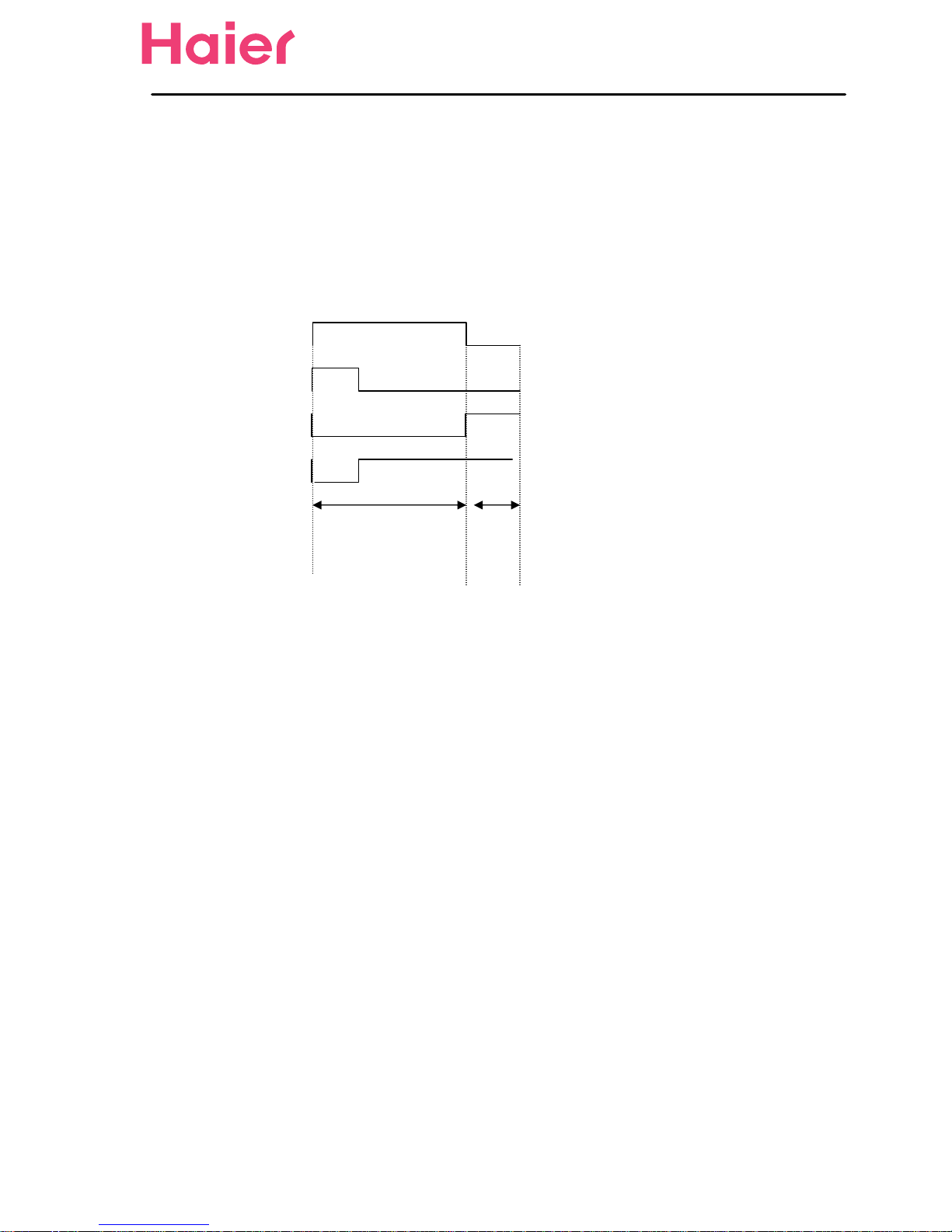
Output 1:
0:
Input 1:
0:
9ms 2ms
2.2. Checkout of errors
The signal reception does not take place until the outdoor unit receive signal HDR from the indoor
unit. At the completion of the signal reception, the data is compared with the inverter data. When
incorrect, all the data is given up. If it is incorrect in 20 seconds of comparison, the compressor,
4-way valve and outdoor fan turn off, giving the abnormal condition and sending out the
corresponding error codes for the abnormalcy of signal delivery and transmission.
2.3. Timer for communication data input /output
After the power supply inputs, the outdoor communication output is HI, waiting for the indoor unit
to send signal.
The timer counter is cleared 0 at the decline of communication, regarding 3 times of 5,6,7 ms.
The status of the communication input PORT determines input signals. When in the next decline of
communication, the timer counter is cleared one again.
HEADER 8 bits, the data and inverter data 48 bits, and the total is 56 bits. After the data has been
received, LO of 10 ms is ready to send signal. The 0 clearance of the timer counter during the
sending takes place in a 1 ms interruption.
HEADER 8 bits, the data and inverter data 48 bits, and the total is 56 bits. After the data has been
sent, Both output LO of 5 ms and output HI of 5ms are ready to receive signal 4 and
communications
Air Conditioner
Edition:2006/1/10
Page 16

A7-6 A5-3 A2-0 C7-0 E7 E6 E5 E4 E3 E2-0
Protocol
MSB
8 2 3 3 8 1 1 1 1 1 3 LSB
READER Oper
ation
mode
Not
in
use
Section Heat
excha
nge
temp.
Not
in
use
Trouble
record
Set
oper
ation
Capa
city
Time
short
age
Abnor
mal
informa
tion
HDR A B C D E F
10000001 00000000 11111111 00000000 11111111 00000000 11111111
HDR: READER indoor unit→outdoor unit 81H 10000001
Communic
ation
Letter
Communication Byte Communication Content Remark
A7, A6
00 stop 01 cooling
10 dehumidify 11 heating
Operation mode
A5
0: normal 1: trial
operation
A4
0: normal
1: timer on operation in
heating
A3
0 ordinary
1 timer on operation in
cooling
A
A2A1A0
000:0
001:1
~
110:6
111:7
Variable
frequency: [set
temp.- room
temp.] section
Fixed frequency:
000: Off
Other: On
C
C7-0
00000000: - infinite
00000001: -53℃
~
10000000: 54℃
11111111:368℃
Indoor unit heat
exchange
temperature
E7 Not in use
E6
0: normal
1: trouble record
indication
E5
0: normal
1: set operation
E
E4 Not in use
Air Conditioner
Edition:2006/1/10
Page 17

E3
0: normal
1: time shortage
operation
E2 E1
00 double-compressor
one-drive-two without
inverter
01 single-compressor
one-drive-two without
inverter
10 One-drive-two with
inverter
E0 Not in use Can not be used
B,D,F: inverter data of A,C and E respectively 8 Bits each
G7-0 I7-4 I3 I21 I0 K76 K54 K3-0
Protocol
MSB
8 8 4 1 2 2 2 4 LBS
HEADER Output
Frequency
Error
code
Err
or
ide
ndi
ty
3 minute
standby
Operation
mode
Oper
ation
sign
al
Moni
tor
signa
l
HDR G H I J K L
11000011 00000000 11111111 00000000 11111111 00000000 11111111
HDA: HEAD 8BIT outdoor unit→indoor unit C3H 11000011
Communi
cation
Letter
Communicat
ion Byte
Communication Content Remark
G G7-G0 00000000:OHZ
│
11111111:255HZ
Variable frequency: output
frequency
Air Conditioner
Edition:2006/1/10
Page 18

I I7-I4 0000: compressor operation abnormal
0001: normal
0010: discharge pipe temperature over-rise
protection
0011: DC wave crest current
0100: outdoor EEPROM abnormal
0101: AC wave crest current(AC current too
high)
0110: not in use
0111: communication abnormal
1000: CT disconnected
1001: undervoltage protection
1010: outdoor thermistor abnormal
1011: not in use
1100: outdoor base plate temperature
over-rise protection
1101: outdoor ambient temperature sensor in
trouble
1110: outdoor coil sensor
1111: not in use
Black indicates the trouble in the
unit with inverter
Red indicates the trouble in the
unit without inverter
Note:
1. Outdoor AC current too high,
i.e., original transformer
troubles A and B.
2. The troubles A and B in the
coil and transformer of previous
outdoor units are separate. Now
the troubles in the outdoor coil
and transformer are no longer
differentiated by A and B.
I3 0: normal
1: error identity
In case of 1, it indicates error.
I2,I1 00: data abnormal
01: normal
10: defrosting operation
11: not in use
In case of 10, the air blower
control operation during
defrosting takes place.
I0 0: normal
1: 3 minute standby
K7,K6 00: stop 01: cooling
10: dehumidifying 11: heating
K5, 0: not double-compressor heating 1:
double-compressor heating
K4 0: normal 1: rated operation
K3 0: normal 1: abnormal operation
K
K2-0 000: normal
1**: RC heating at the non-communication
side starts in the timer
*1*: RC cooling at the non-communication
side starts in the timer
**1: both units are in operation
H, J, L: inverter data of G, I and K respectively 8 bits each
Air Conditioner
Edition:2006/1/10
Page 19

3. Single-unit cooling operation
3.1. When the single unit’s indoor unit gives a cooling signal, the corresponding outdoor
compressor carries out cooling operation. During the operation, the outdoor fan operates 1
second before the compressor operates.
3.2. When changed from heating to cooling, the compressor stands by for 3 minutes, the outdoor
fan operates to blow off remaining heat and stops 30 seconds later.
3.3. When the outdoor ambient temperature T1≥38℃, the outdoor fan runs at the high speed.
There is a return difference of 2℃ for the change between high and medium speed.
When the outdoor ambient temperature T1≤26℃, the outdoor fan runs at the low speed. There
is a return difference of 2℃ for the change between low and medium speed.
When the outdoor ambient temperature T1≤8℃, the outdoor fan is in a cycle of 1 minute stop
and 3 minute run. There is a return difference of 2℃ for the change between low speed and run
and stop.
3.4. Once the fan operates in a mode, it must operate for more than 45 seconds.
There is a temperature cut-off protection: when the indoor coil temperature higher than T_CPS (68
℃) and maintains for 10 seconds, both the compressor and outdoor fan stop. The compressor will
not restart in 3 minutes until the coil temperature lower than T_CP R(50℃). The indoor fan is
controlled the same as the thermostat is OFF.
4. Double-unit cooling operation
4.1. When the indoor unit gives out a double unit cooling signal, outdoor compressor A starts
cooling operation. During the operation, the outdoor fan runs 1 second before compressor A
operates, 20 seconds later, outdoor compressor B starts cooling operation.
4.2. Once a compressor starts, the other compressor will not start in 20 seconds from the start.
4.3. When changed from heating to cooling, the compressor stands by for 3 minutes. When both
compressors are in the strand-by status, the outdoor fan stops. Otherwise, it operates. The status
of the fan depends on the number of the compressors that operate.
4.4. When the outdoor ambient temperature T1≥30℃, the outdoor fan runs at the high speed.
There is a return difference for the change between high and medium speed;
When the outdoor ambient temperature T1≤23℃, the outdoor fan runs at the low speed. There
is a return difference for the change between low and medium speed;
When the outdoor ambient temperature T1≤5℃, the outdoor fan is in a cycle of 1 minute stop
Air Conditioner
Edition:2006/1/10
Page 20

and 3 minute run. There is a return difference of 2℃ for the change between low speed and run
and stop.
4.5. Once the fan operates in a mode, it must operate for more than 45 seconds.
4.6. There is a temperature cut-off protection: when a indoor coil temperature higher than T_CPS
(68℃) and maintains for 10 seconds, the corresponding compressor stops. The compressor will
not restart in 3 minutes until the coil temperature lower than T_CP R(50℃). The indoor fan is
controlled the same as the thermostat is OFF.
4.7. In the case of double-unit cooling, one compressor stops and it changes to the single-unit
operation. The fan is controlled in the single-unit operation mode. It stops 30 after blowing off
the remaining heat only if both compressors turn off at the same time.
5. Single unit heating operation:
5.1. When the single unit’s indoor unit gives a heating signal, the corresponding outdoor
compressor carries out cooling operation. During the operation, the outdoor fan and 4-way valve
operate 1 second before the outdoor fan operates.
5.2. When changed from cooling to heating, the compressor stands by for 3 minutes, the outdoor
fan stops.
5.3. When the outdoor ambient temperature T1≤3℃, the outdoor fan runs at the high speed. There
is a return difference of 2℃ for the change between high and medium speed.
When the outdoor ambient temperature T1≥13℃, the outdoor fan runs at the low speed. There is a
return difference of 2℃ for the change between low and medium speed.
5.4. Once the fan operates in a mode, it must operate for more than 45 seconds.
5.5. There is a high temperature protection and a temperature cut-off protection.
High temperature protection: When the indoor coil temperature higher than T_OFS (56℃), the
outdoor fan stops; when the coil temperature falls to T_OFR (52℃), the outdoor fan restarts. The
outdoor fan stops for more than 45 seconds.
High temperature cut-off protection: When the indoor coil temperature higher than T_CPS (68℃)
and maintains for 10 seconds, both the compressor and outdoor fan stop, and the indoor fan operates
as the thermostat is Off. The compressor will not restart in 3 minutes until the coil temperature
lower than T_CP R(50℃).
6. Double-unit heating operation
6.1. When the double-unit’s indoor unit gives out a heating signal, outdoor compressor A starts
Air Conditioner
Edition:2006/1/10
Page 21

heating operation. During the operation, outdoor compressor A and the 4-way valve operate 1
second before the fan starts, 20 seconds later, outdoor compressor B starts heating operation.
6.2. Once an outdoor compressor starts, the other compressor will not start in 20 seconds from the
start.
6.3. When changed from cooling to heating, the compressor stands by for 3 minutes. When both
compressors are in the strand-by status, the outdoor fan stops. Otherwise, it operates. The status
of the fan depends on the number of the compressors that operate.
6.4. When the outdoor ambient temperature T1≤10℃, the outdoor fan runs at the high speed.
There is a return difference for the change between high and medium speed;
When the outdoor ambient temperature T1≥20℃, the outdoor fan runs at the low speed. There
is a return difference for the change between low and medium speed.
6.5. Once a fan operates in a mode, it must operate for more than 45 seconds.
7. Cooling and heating operations take place at the same time:
7.1. When one of the indoor units gives out a cooling signal and another unit gives out a heating
signal at the same time, the outdoor fan operates at the low speed.
7.2. When the indoor unit gives the value of coil temperature, the outdoor fan runs at the low speed if
the heating outdoor unit judges high load.
7.3. When outdoor ambient temperature T1≥28℃, there is no heating operation.
7.4. When outdoor ambient temperature T1≤7℃, there is no cooling operation.
7.5. Once a compressor starts, the other compressor will not start in 20 seconds from the start.
8. Single-unit heating operation with heat load:
8.1. In the single-unit heating operation, the indoor unit gives out the value of the coil temperature,
and the outdoor unit judges whether to start in the high load protection operation based on the
value of the coil temperature it has received. If the conditions for high load protection are met, the
outdoor fan stops immediately. It will restart 45 seconds later if the signal for the outdoor heat load
disappears. Otherwise, the outdoor fan will continue to stop until the signal for the outdoor heat
load disappears. The signal for heat load is as follows:
High temperature protection: When the indoor coil temperature higher than T_OFS (56℃), the
outdoor fan stops; when the coil temperature falls to T_OFR (52℃), the outdoor fan restarts. The
outdoor fan stops for more than 45 seconds.
Air Conditioner
Edition:2006/1/10
Page 22

High temperature cut-off protection: When the coil temperature higher than T_CPS (68℃) and
maintains for 10 seconds, both the compressor and outdoor fan stop, and the indoor fan operates as the
thermostat is Off. The compressor will not restart in 3 minutes until the coil temperature lower than
T_CP R(50℃).
8.2. In the single-unit heating operation, the current in the compressor is larger than 5.8A, and the
outdoor fan stops. 45 seconds later, the current in the compressor is less than 5.3A, and the outdoor fan
operates in normal condition(the compressor does not detect current within 30 seconds after its start),
the current in the compressor is larger than 5.3Aand less than 5.8A, and the outdoor fan does not
restore.
9. Double-unit heating operation with heat load
9.1. In the double-unit heating operation, the indoor unit gives out the value of the coil temperature,
and the outdoor unit judges whether to start in the high load protection operation based on the
value of the temperature it has received. If the conditions for high load protection are met, the
outdoor fan stops immediately. It will restart 45 seconds later if the signal for the outdoor heat load
disappears. Otherwise, the outdoor fan will continue to stop until the signal for the outdoor heat
load disappears. The signal for heat load is as follows:
High temperature protection: When the indoor coil temperature higher than T_OFS (56℃), the
outdoor fan stops; when the coil temperature falls to T_OFR (52℃), the outdoor fan restarts. The
outdoor fan stops for more than 45 seconds.
High temperature cut-off protection: When the coil temperature higher than T_CPS (68℃) and
maintains for 10 seconds, both the compressor and outdoor fan stop, and the indoor fan operates as
the thermostat is Off. The compressor will not restart in 3 minutes until the coil temperature lower
than T_CP R(50℃).
9.2. When the outdoor single-unit gives out the heat load signal, the outdoor fan stops immediately,
45 minutes later, the heat load signal disappears, and the outdoor fan operates.
9.3. In heating operation, any of the current in the compressor is larger than or equal to 5.8A , and
the outdoor fan stops. The current in the compressor is less than or equal to 5.3A, and the outdoor
fan restores (the compressor does not detect current within 30 seconds after its start), the current in
the compressor is larger than 5.3A and less than 5.8A, and the outdoor fan does not restore.
10. Current peak protection
Air Conditioner
Edition:2006/1/10
Page 23

10.1. The current in the compressor is larger than 10 Afor more than 5 seconds, The compressor which
has the highest current will stop(the compressor does not detect current within 10 seconds after its
start) and 3 minutes later it will continue to operate.
10.2. The compressor will no longer operate if overcurrent protection occurs 4 times in a row within
30 minutes, and the output transformer signal fails. In the double-unit operation, if one of the
compressors stops due to the current too high, the other system is a single system.
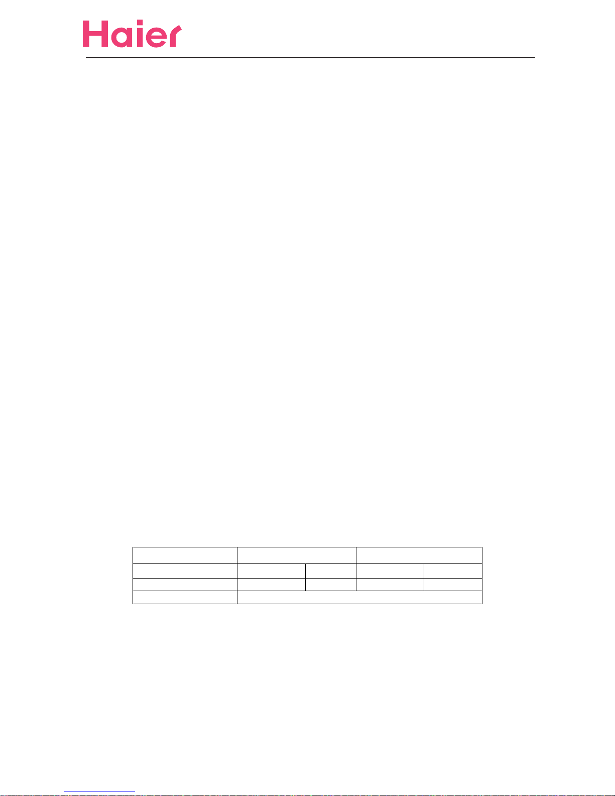
11. Single-unit defrosting operation (outdoor judgement)
Defrosting control
11.1. Conditions for starting in the defrosting operation
The heating compressor starts and operate continuously for 10 minutes. After the compressor has
been operating for 45 minutes in total (the defrosting operation ends, or when starting in the
cooling mode, the compressor totals the operating time for zero clearance), detecting the
defrosting sensor TE (detecting the frosting of the outdoor heat exchanger) and the outdoor
ambient temperature sensor TA for straight 2 minutes, provided the following conditions are met,
it will start for the defrosting operation: TE≤C×TA-α
Where,
C: T A <0℃
C=0.8
TA≥0℃
C=0.6
αcan be selected according to the data of EEPROM as follows:
Selection of
Jumper
L M H
α(℃) 10 8 6
In the place where it tends to frost, it is preferred to choose H. In the place where it does not intend to
frost, it is preferred to choose L. It is set M at delivery.
During the defrosting operation, the temperature control starts -15℃≤C×TA-α≤-2℃
Note: If the result of the calculation from C×TA-α is less than -15℃, -15℃ applies. If the result
of the calculation from C×TA-α is larger than -2℃, -2℃ applies.
11.2. Interval of defrosting
Air Conditioner
Edition:2006/1/10
Page 24

When the result of the calculation from C×TA-α falls in the range of -15℃≤C×TA-α, the
interval between two defrosting operations is 45 minutes.
When the result of the calculation from C×TA-α falls in the range of C×TA-α<-15℃, the
interval between two defrosting operations is 55 minutes.
11.3. Defrosting operation
At the beginning of defrosting, the compressor is halted for the first one minute, but the outdoor fan
operates, 50 seconds later, the 4-way valve is OFF.
During the defrosting operation, such protections as the compressor’s current protection are available.
The compressor may be interrupted for its protection or due to a trouble, and restore after 3 minutes. If
it remains in the defrosting period, it will still start to defrost. The start of the compressor is made by
the rules for the start of the defrosting compressor. (if it cannot restore 3 times in a row, it will be dealt
with as in trouble and cancel defrosting.)
11.4. Once starting to defrost, the compressor must be guaranteed at least 2 minutes of operation
before canceling defrosting. As for the conditions to cancel defrosting, it will restore to the heating
operation from the defrosting operation as long as any of the following conditions is met.
(1) . The outdoor heat exchanger temperature is above 7 degrees for consecutive 80 seconds.
(2) . The outdoor heat exchanger temperature is above 5 degrees for consecutive 12 seconds.
(3) . The defrosting operation has lasted 9 minutes.
11.5. After the conditions for cancellation of defrosting are met, the following operations will follow:
The compressor stops, the outdoor fan starts, 50 seconds later, the 4-way valve is engaged, and 60
seconds later, the compressor operates.
12. Double-unit defrosting operation (outdoor judgement)
After receiving the signal to stop the indoor unit during the defrosting period, the unit must not be
turned off until the outdoor defrosting lasts more than 2 minutes.
When the double units are activated for defrosting, the activation of compressor B is 20 minutes later
than that of compressor A.
Conditions for ending defrosting: It will restore to the heating operation from the defrosting operation
as long as any of the following conditions is met.
(1) . The temperatures on both outdoor heat exchangers are above 7 degrees for consecutive 80
seconds.
(2) . The temperatures on both outdoor heat exchangers are above 5 degrees for consecutive 12
Air Conditioner
Edition:2006/1/10
Page 25

seconds.
(3) . The defrosting operation has lasted 9 minutes.
The starting conditions and control process for the double-unit are same as that for single-unit
defrosting, the only difference is that the activation of compressor B lags that of compressor A.
13. Alarming operation
1. When the whole unit is in normal operation, the alarm light is always on, but does not flash.
2. When the outdoor temperature sensor short-circuited or disconnected, the outdoor fan always
operates at the medium speed and will restore automatically after the sensor comes to normal.
3. When the temperature sensors on the pipes A and B short-circuited or disconnected, the double
unit will not carry out defrosting operation. During heating, this signal is sent to the indoor unit,
but no sending for other operating conditions. When sent to the indoor unit, the whole unit stops.
The signal is sent to the indoor unit which coil is operating abnormally, and the corresponding
indoor unit indicates trouble.
4. When the temperature sensor short-circuited or disconnected or the current transformer fails, the
alarm light flashes in the following manner; when the current transformer fails, the signal is sent
to the indoor unit that operates abnormally, and the corresponding indoor unit indicates trouble:
Air Conditioner
Edition:2006/1/10
Page 26

H2SM-14/18C03/R2
22
Codes and Description
Code indication
indoor
Description
Outdoor led1
blinks times
Power timer operate
Operate heating cooling
★ ■ ■
Room temperature sensor failure --
★ □ □
Heat-exchange sensor failure --
★ □ ★
Indoor EEPROM error ---
■ □ ★
Indoor fan motor malfunction --
Indoor
Malfunction
■ ■ ★ Communication Error (between indoor and outdoor unit)
3 or 7
outdoor EEPROM error 1
★ □ ■ Outdoor Senistor Error
2
outdoor unit A’s coil sensor failure
5
Outdoor
Malfunction
outdoor unit B’s coil sensor failure
9
explanation □on★flash■off
Trouble Shooting
★ ■ ■: Room temperature sensor failure CN8
★ □ □: Heat-exchange sensor failure CN8
YES
NO
YES
whether terminal CN8 on
indoor PCB contact wellt?
Pull out the terminals on the indoor mainboard and
reinsert them
Pull the sensor out of the mainboard
1) Measure the value of resistance Between its two
jumpers
2) Measure the temperature at the room temperature
sensing head.
Check the value of the
sensor to see whether the
sensor is dama
ged or not?
NO
Sensor is broken,replace it with new sensor
The indoor PCB is broken, replace with new indoor PCB
Page 27

H2SM-14/18C03/R2
23
★ □ ★: Indoor EEPROM error: Replace the PCB of indoor unit
■ □ ★:Indoor fan motor malfunction
Ye s
Ye s
YES
NO
whether terminal CN7
and CN11 on indoor PCB
well inserted or not?
Pull out and reinsert the terminals
Electrify the machine again and turn it on in the cooling
operation, Measure voltage between the positions 1 ( red
wire)
and 5( black wire) of Terminal CN1 on the indoor PCB
NO
the indoor pcb is damaged and need replace
. the voltage is about
90-200vac
check whether motor
can run when
turn on the unit
the indoor motor is damaged and need
replace
NO
When motor is running Measure
whether there is voltage
pulse(0-5VDC) between the
positions 2 (middle wire) and
3(
black wire) of Terminal CN7
on the indoor PCB
the indoor motor is damaged and need
replace
the indoor pcb is damaged and need replace
NO
Page 28

H2SM-14/18C03/R2
24
LED1 of outdoor pcb flashes once: outdoor EEPROM error: Replace the PCB of outdoor unit,
★ □ ■
LED1of outdoor pcb flashes twice: Outdoor ambient Sensor failure CN1,
YES
NO
YES
whether terminal CN1 on
outdoor PCB contact well?
Pull out the terminals on the outdoor mainboard and
reinsert them
Pull the sensor out of the mainboard
3) Measure the value of resistance Between its two
jumpers
4) Measure the temperature of
Outdoor ambient
Check the value of the
sensor to see whether the
sensor is dama
ged or not?
NO
Sensor is broken,replace it with new sensor
The outdoor PCB is broken, replace a new one
Page 29

H2SM-14/18C03/R2
25
■ ■ ★ :Communication fault between indoor and outdoor system
Yes
NO
Yes
NO
YES
NO
YES
NO
NO YES
NO
YES NO
NO
YES
Check whether the linking cable
between the indoor and outdoor
is not well connected
Reconnect the linking cable;
If unit A have error , please turn
on A and B both,check whether B
is fine
please reverse the outdoor
connecting wires A(C) and B (C)
between unit A and B,
if A is error and B is fine, indoor
unit A PCB is damaged
if A is fine and B has error,the
outdoor unit main PCB is damaged
please check whether the
connecting of L or N is reversed of
the two units
reconnect the L and N wires
Check whether the LED1
on the outdoor pcb is on
the outdoor PCB is damaged
check whether the voltage of
CN7 in outdoor pcb is about
198-253VAC
check whether fuse of outdoor
pcb is broken
reaplace the fuse with
T3.15A 250V
check whether the voltage of
CN4
in outdoor pcb is about 12VAC
check whether the wire from
terminal block to out pcb is well
connected
Reconnect the linking
wire
the transformer is bad
the outdoor PCB is damaged
Page 30

H2SM-14/18C03/R2
26
LED1 of outdoor pcb flashes 5 or 9 times outdoor unit A or B’s coi sensor failure CN2
YES
NO
YES
whether terminal CN2 on
outdoor PCB contact well?
Pull out the terminals on the outdoor mainboard and
reinsert them
Pull the sensor out of the mainboard
5) Measure the value of resistance Between its two
jumpers
6) Measure the temperature of
outdoor unit A or
B’s coi
Check the value of the
sensor to see whether the
sensor is dama
ged or not?
NO
Sensor is broken,replace it with new sensor
The outdoor PCB is broken, replace a new one
Page 31

Air Conditioner Edition:2005/11/18
TROUBLE SHOOTING
27
Page 32

Air Conditioner
28
Trouble shooting
Before asking for service, check the following first.
Normal
Performance
inspection
Noise is heard
Phenomenon
Cause or check points
The system does not restart
immediately.
Smells are generated.
Mist or steam are blown out.
Multiple
check
Does not work at all.
Poor cooling
Application temp. range of air conditioner -7oC~43oC.
When unit is stopped, it won't restart
immediately until 3 minutes have elapsed
to protect the system.
When the electric plug is pulled out and
reinserted, the protection circuit will work
for 3 minutes to protect the air conditioner.
During unit operation or at stop, a swishing
or gurgling noise may be heard. At first 2-3
minutes after unit start, this noise is more
noticeable. (This noise is generated by
refrigerant flowing in the system.)
During unit operation, a cracking noise may
be heard. This noise is generated by the
casing expanding or shrinking because of
temperature changes
Should there be a big noise from air flow in
unit operation, air filter may be too dirty.
This is because the system circulates smells
from the interior air such as the smell of
furniture, cigarettes.
During COOL or DRY operation, indoor unit
may blow out mist. This is due to the sudden
cooling of indoor air.
Is power plug inserted?
Is there a power failure?
Is fuse blown out?
Is the air filter dirty? Normally it should be
cleaned every 15 days.
Are there any obstacles before inlet and outlet?
Is temperature set correctly?
Are there some doors or windows left open?
Is there any direct sunlight through the
curtain)
window during the cooling operation?(Use
Are there too much heat sources or too many
people in the room during cooling operation?
Page 33

Number
Trouble
phenomenon
Description
Parts that may appear problems
and the Cause
Prepared parts
and tools
Applicable
machine
1
Not work with
remote
controller
Use the
remote
controller to
boot
machine
and it
doesn’t
work
7805,transformer, piezo
resistance, fuse,remote controller,
receiver. If it can be booted by
using manual emergency switch,
that indicate the power cable and
wiring board are electriferousˈ
remote controller or receiver isn’t
well˗else check whether piezo
resistance ,fuse and 7805 are
wellDŽ
7805,transfor
mer, fuse,
piezo
resistance,
remote
controller,
receive,avome
ter
invariable
frequency
split unit
2
Outdoor fan
motor
doesn’t work
Outdoor
fan motor
doesn’t run
when
cooling or
heating
Optical SCR, indoor P.C. board.
Check the 2# and 4# terminal
block of indoor unit, if it has 220V
voltage, wiring board is normal,
then check whether the optical
SCR is good, replace it if it has
flaw˗else check whether there are
something wrong with connecting
lineˈoutdoor fan motor capacitor
and coil assemblyDŽ
Optical SCR,
indoor P.C.
board ,
outdoor fan
motor
capacitor,
outdoor fan
motor,avomet
er
invariable
frequency
split unit
3
Indoor fan
motor
doesn’t work
Indoor fan
motor
doesn’t run
when
cooling or
heating
Optical SCRˈindoor P.C. board DŽ
Check whether indoor fan motor
has 80-170V voltageˈif it hasˈ
wiring board is normal, then check
whether the optical SCR is good,
replace it if it has flaw˗else check
whether there are something
wrong with connecting lineˈindoor
fan motor capacitor and coil
assemblyDŽ
Optical SCRˈ
indoor P.C.
board , indoor
fan motor
capacitor,
indoor fan
motor,avomet
er
invariable
frequency
split unit
4 Not heating
Cooling but
not heating
Indoor P.C. board , four-way valve
coil, body of four-way valveˈCheck
the 2# and 3# terminal block of
indoor unit, if it has 220V voltage
when heating but no when cooling,
then P.C. board is abnormal; else
check whether four-way valve coil
and the body of four-way valve are
damagedDŽ
Indoor P.C.
board ,
four-way valve
coil, body of
four-way
valve,
avometer
invariable
frequency
split unit
Air Conditioner
Edition:2006/1/10
29
Abnormality Diagnosing
Page 34

5
Indoor unit
make water
Oriented
wind panel
or drain
pan makes
water when
used
Drain pan, drain hose. Check
whether the indoor unit is installed
horizontal, drain hose of indoor
unit is leveled off ,the hole is over
high ˈfilter and drain hose is dirty
and walled upǃdrain pipe is
underwaterDŽ
drain pan,
drain hose
invariable
frequency
split unit
6
Compressor
doesn’t work
running
indicator
lights upˈ
but
compressor
doesn’t
work
Indoor P.C. board , startup capacity
for compressor, overheat protector,
compressor. Check the 1# and 2#
terminal block of indoor unit
whether it has single AVˈif not then
examine the power relay of P.C.
board ˈelse check overheat
protector, startup capacity for
compressor and compressor itself
Indoor P.C.
board , startup
capacity for
compressor,
overheat
protector,
compressor,av
ometer
invariable
frequency
split unit
7
The outdoor
fan motor
and
compressor
don’t work
The
running
lamp of air
conditioner
lights but
the outdoor
fan motor
and
compressor
don’t run
Remote controller ǃelectrolytic
capacitor of 2500UFǃ7805ǃ
outdoor heat exchanger sensor
and ambient temperature sensor.
Use temperature key of remote
controller to watch how much
times the timing lamp glitters and
judge what’s the trouble .If there is
no glitter we should check the
terminal block to see if there is AC
voltage about 220V.Check the
electrolytic capacitor of 2500UF
and see if there is current about
310V.Examine the output of the
7805 and switch transformer
together with the resistance of the
sensor.
Remote
controller ,elec
trolytic
capacitor of
2500UFǃ
7805ǃ
outdoor heat
exchanger
sensor and
ambient
temperature
sensorǃ
avometer
Little split
unit of
frequency
conversion
8
The outdoor
fan motor
runs but the
compressor
doesn’t run
The running
lamp of air
conditioner
lights ,the
outdoor fan
motor works,
but the
compressor
doesn’t work
Power modelǃswitch transformerǃ
compressor. Check the temperature key
of remote controller to watch how many
times the timing lamp glitters and judge
what’s the trouble. Examine the two
ends of PN to see if there is DC voltage
about 310V.Four group DC power
resource of 15V.Check the triphase coil
assembly of the compressor and see if
they are the same.
Power modelǃ
switch
transformerǃ
compressorǃ
avometer
Little split
unit of
frequency
conversion
Air ConditionerEdition:2006/1/10
30
Page 35

9
Don’t make
heat
The air
conditioner
can
refrigerate
but can’t
make heat
Outdoor P.C. Boardǃ4 way valve
coilǃ 4 way valve body. Examine
the CN204 at Outdoor P.C. Board
and watch if there is 220V
voltage .If there doesn’t have we
can judge that the P.C. Board is
bad. If there has, we need to
connect and check the whether the
4 way valve coil and the 4way
valve body have been damaged .
Outdoor P.C.
Boardǃ4way
valve coilǃ 4
way valve
bodyǃ
avometer.
Little split
unit of
frequency
conversion
10 Show error
code E8
The
machine
doesn’t
work and
shows error
code E8
Multimeter negative generatorǃ
indoor P.C. board ǃconnecting and
inserting lines .Check if the
Multimeter negative generator is
plane and the grounding (CF) is
touching well, then examine not
only whether the indoor P.C. Board
and control board have been
damaged or not but also the
connecting lines are good.
Multimeter
negative
generatorǃ
indoor P.C.
Boardǃ
control
board ǃ
grounding
(CF)ǃ
avometer.
The series
of
frequency
fixed
cabinet
type
11 Can’t start
The air
conditioner
can’t start
Transformerǃindoor
microcomputer plateǃfuse. Check
if the transformer has been
burned. power wave filterǃ
LX102.Check whether the fuse
and indoor microcomputer plate
have been damaged.
Transformerǃ
power wave
filterǃindoor
microcompute
r plateǃfuseǃ
avometer.
The series
of
frequency
fixed
cabinet
type
12
Show error
code F11
When the
air
conditioner
has run
about
5minutes
the indoor
unit shows
the error
code F11.
The system pressureǃoutdoor P.C.
BoardǃPower source voltageǃ
power modelǃthe connecting lines
of compressor. The cause is that
protective action has been taken
when it runs with large burden,
there is more refrigerant than it
should be .Examine the outdoor
P.C. BoardǃPower source voltageǃ
power model and see whether they
have been damaged and the
connecting lines touch well, if not,
adjust it to be normal.
outdoor P.C.
BoardǃPower
source
voltageǃpower
model .
The
machine of
frequency
conversion
split unit
Air ConditionerEdition:2006/1/10
31
Page 36

Air Conditioner Edition:2005/11/18
INSTALLATION
32
Page 37

Air Conditioner
Edition:2006/1/10
12
12
C
8
D
15
E
Page 38

Air Conditioner
Edition:2006/1/10
3/8
Page 39

Air Conditioner
Edition:2006/1/10
Page 40

Air Conditioner
Edition:2006/1/10
Page 41

Air Conditioner
Edition:2006/1/10
Indoor unit A
Indoor unit B
YEL/GRN
RED
1 2 3
1 2 3
BLK
WHT
YEL/GRN
RED
BLK
WHT
WHT
BLK
WHT
BLK
RED
RED
POWER
YEL/GRN
YEL/GRN
BRN
BLU
{
YEL/GRN
1(L)
2(N)
3(R)
1(L)
2(N)
3(R)
1(L)
2(N)
Outdoor unit
5
Page 42

Air Conditioner
Edition:2006/1/10
Page 43

Air Conditioner
Edition:2006/1/10
3.The purging Method of the indoor unit B is the same as the indoor unit A.
The unit A and unit B are seperated and disconnected connected for the different compress.
9.52
9.52
3/8
3/8
Page 44

1.Cut pipe
3.Insert the flare nut
4.Flare pipe
2.Remove burs
0~0.5mm 1.0~1.5mm 1.5~2.0mm
Flare tool for R410A
Clutch-type
Conventional flare tool
clutch-type(Rigid-type)
Wing-nut type (Imperial-type)
Air Conditioner
Edition:2006/1/10
Page 45

Air Conditioner
Edition:2006/1/10
Page 46

Air Conditioner
Edition:2005/11/18
CIRCUIT AND WIRING DIAGRAM
Page 47

H2SM-14/18C03/R2
43
1 2 3 4 5 6 78
A
B
C
D
8
7654321
D
C
B
A
R17
10k
C12
102
C13
104
C16
102
12345
CN13
13
2
XT1
8M
R15
10k
R24
10K
R18
4.7k
R41
1K
R52
10K
+5
C5 102
R30
10K
R28 1K
R27 10K
+5
R29 10K
Q2
2SC2412
Q1
2SC2412
1
2
CN9
1
2
ZJ1
1
2
3
CN7
+5
C43
103
+5V
R50
51K
R14 1K
+5
IC10
TLP3526
1
2
3
CN1
C39
2UF 450V
+5V
R57
220
R42
3456
7
8 1
2
IC2
24C02
+5
E6
4.7UF/50V
E7 4.7UF/50V
1
2
3
4
CN8
R44 1K
R45 1K
R35 3.3K 1%
R34
20K 1%
+5
C2 104
R46
1K
C15
102
C10
102
C9
102
Q4
2SC2412
SDA
SCL
1234567
89
10111213141516
IC4
2003
C
D
B
A
+12
C4
104
+5
C6
103/50V
E5
100u/16v
C18
104/50V
+5
R65
10k
C36
103/50v
.
RL1
JQ1A-12V
+12
R20 10K
+5
R10 10K
1
2
3
4
CN6
R36
1K
R37
10K
+5V
R8
10K
+5V
R7
10K
C14
104
BUZ1
BEEP-PKM13EPY-4002
Q5
2SC2412
R11
10K
R49
100
R9
4.7K
R1
1M
R31
10K
+12V
C41
102
R2
10K
R3
1K
C1
102
+5V
02 IRQ
07
08
PTF4/TBCH0
PTF3/TBCH3
48
49
PTH1/KBD3
PTH1/KBD4
03
RST
21
VSS GND
GNDAVSS/VRE
45
60
PTC0
PTF7
10
13
PTE0/TXD
56
VSSA GND
14
PTE1/RXD
PTE2/TACH0
15
25
PTG2/KBD2
PTE3/TACH1
16
17
PTE4/SS
18
19
20
PTE5/MISO
PTE6/MOSI
PTE7/SPSCK
PTC4
01
26
PA0
27
PA1
28
PA2
29
PA3
30
PA4
31
PA5
32
PA6
33
PA7
38 PTB4
R32
10K
50 PTD4
34
PTB0/ATD0
35
PTB1/ATD1
39
40
41
42
43
46
PTB5/ATD5
PTD6/ATD6
PTB7/ATD7
PTD0
PTD1
PTD2
47PTD3
VDDAREF 44
06
05
PTF1/TACH3
PTF2/TBCH2
57
CGMXFC
54
55
VDDA
VREFH
5958OSC1
OSC2
51PTD5
PTD6/TACLK 52
53
62
63
64
PTD7
PTC2/MCLK
PTC3
PTC5
PTF0/TACH2 04
22
36
37
PTB3/ATD3
PTB2/ATD2
VDD
09
NC
61
23
24
PTC1
PTG1/KBD1
PTG0/KBD0
1
CON1(red)
C19
104
MC68HC908AB32
+12v
R13 10K R12
10K
R26
10K
5v
11
12
PTF5
PTF6
C7
104/50V
C3
103
C29
104/50v
R53 1K
SW1
220V-N
R59
4.7K
1
CON2(white)
220V-L
220V-N
R66 27
C25
102/50V
C27
102/50V
C26
102/50V
C47
104/50V
E13
100u/25v
R69 10K
R68 10K
R67 10K
R70 560
R71 560
R72 560
53
52
51
R88 560
C38
102/50V
61
R16
10k
+5
R21 10K
SW2
R73
10K
D6
1N4007
1
CON5
R81
330K 1/4W
R82
330 1/4W
C22
102
R85 2.2K 1/4W
R87
10K 1/4W
+5
R86
10K 1/4W
R80
2.2k 1/4W
IC12
TLP421
+5
R83
2.2K
1
N
C49
103/50V
R84
6.8K 2W
LED1
GREEN
+5
Q9
2SC2412
IC14
TLP371
+5
1
24
5
6
1
2
3
4
D8
1N4007
Q3
2SC2412
R4 4.7K
R38 10K
+5V
R39 4.7K
Q10
2SC2412
D7
RLS4148
R64 10K
R40
10K
+5V
R8922K
R91
4.7K
5v
SW3
R92
10K
R93
10K
Q11
2SC2412
D1-D4
IN4007
FUSE
3.15A
T1
D5
1N4007
E8
2200UF/25V
Z1
561K
C40
104/275V
CN4
B2P3-VH-A
IC9
7805
CN3
0-171825-3
CN2
RTB-1.5-2P
C35
104
+12+5
C17
104
R51
3.3K
Q8
2SB1197
R54
680
R43
3.3K
1
2
3
4
5
6
7
CN5
SJ20-07WX
R47 560 1/4W
R5
10K
C24
0.01u/275V120 1W
L1
125uH
+5
R58 10K
R25
10K
R6
10K
R97
10K
R95
10K
R96
10K
R98
10K
R33
10K
5v
+5V
+5V
E4
100u/16v
C28
104/50V
+5
E15
470UF/16V
C42
104/50V
+12
E9
100u/25v
Page 48

Air Conditioner
Edition:2006/1/10
Page 49

W:
Air Conditioner
Edition:2006/1/10
Page 50

Sincere Forever
Haier Group
Haier Industrial Park, No.1, Haier Road
266101, Qingdao, China
http://www.haier.com
Air Conditioner
Edition:2006/1/10
 Loading...