

Haier AS18ND1HRA-WHITE, HSU18VHGL-G, 1U18FE2ERA, HSU18VHGL-W, AS24BS4HRA Service Manual
...Page 1
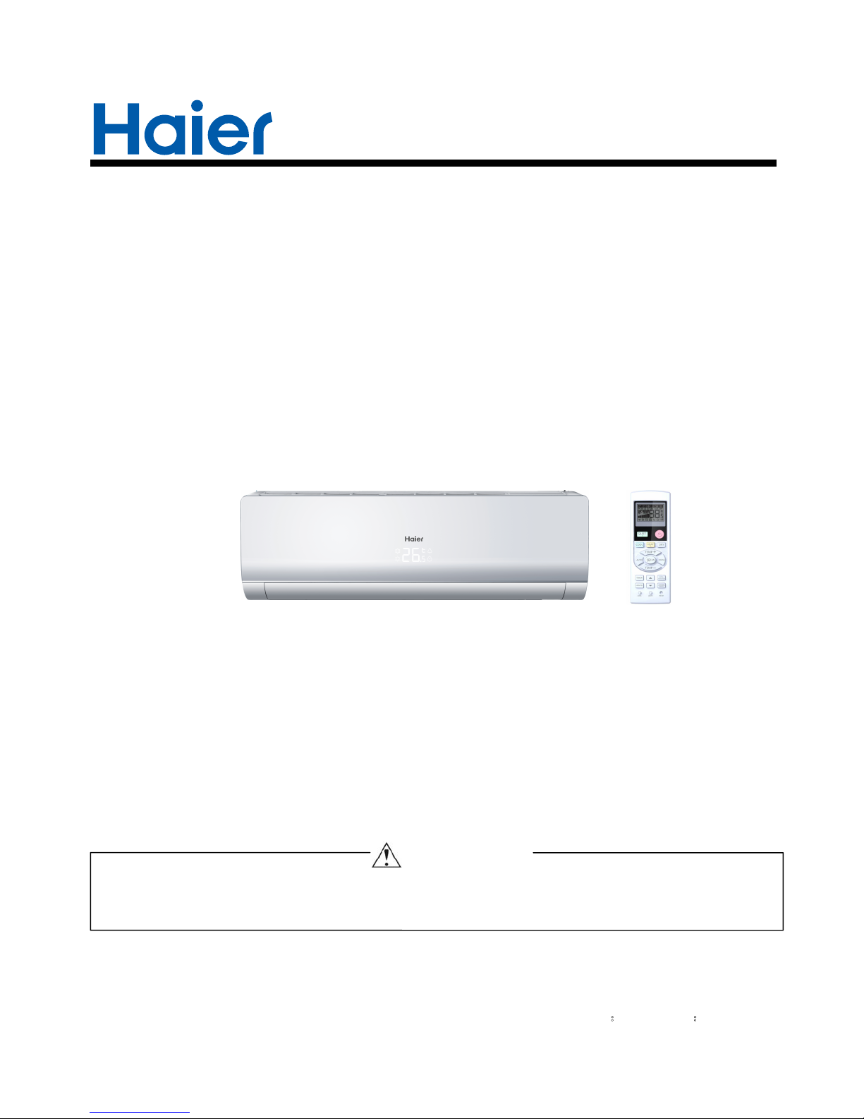
SERVICE MANAUL
Wall Mounted Type
DC Inverter FREE MATCH N-Series
AS18ND1HRA-WHITE
HSU18VHGL-G
Model No.
This service information is designed for experienced repair technicians only and is not designed for use by the general public.
It does not contain warnings or cautions to advise non-technical individuals of potential dangers in attempting to service a product.
Products powered by electricity should be serviced or repaired only by experienced professional technicians. Any attempt to service or
Repair the product or products dealt with in this service information by anyone else could result in serious injury or death
WARNING
2014 (Qingdao Haier Air Conditioner General corp. , Ltd)
All rights reserved. Unauthorized copying and distribution is a violation of law
Haier Group
Version:V1 Date:2014-05-25
Page 2
Table of contents
Domestic air conditioner
Contents
1. Introduction ............................................................................................ 1
2. Features ................................................................................................ 7
3. Specifications ........................................................................................ 8
4. Sensors list............................................................................................ 9
5. Piping diagrams .....................................................................................10
6. Printed Circuit Board Connector Wiring Diagram..................................11
7. Functions and Control ...........................................................................
8. System configuration.............................................................................
9. Dimensional drawings ...........................................................................
10. Conter of gravity..................................................................................
11. Service Diagnosis ................................................................................
12. Circuit diagrams
..................................................................................
14
59
43
42
42
25
Page 3
Introduction
Domestic air conditioner
1 Introduction
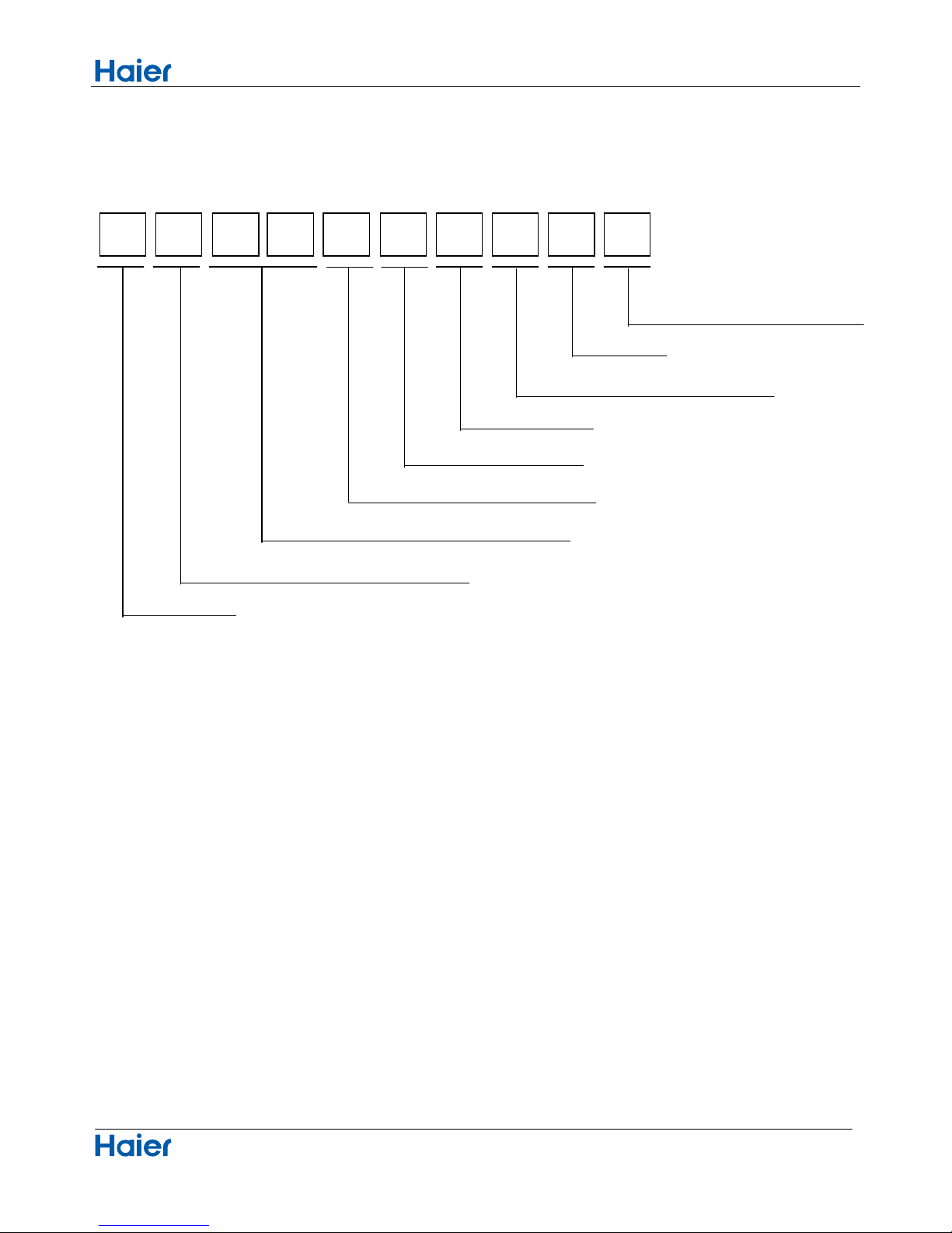
1.1 Model name explanation
A S 1 8 N D 1 H R A
Indoor unit
Type of indoor unit: S (wall-mounted)
Nominal cooling capacity (18000BTU/h)
Version number
Heat pump & R410A refrigerant
DC inverter
Apply toT1; 208~230V60HZ/1ph
1
Platform of indoor units: N (N platform)
50N Platform
Page 4

Intuoduction
Domestic air conditioner
1.2 Safety Cautions
Be sure to read the following safety cautions before conducting repair work.
The caution items are classified into “Warning” and “Caution”. The “Warning” items are especially important
since they can lead to death or serious injury if they are not followed closely. The “Caution” items can also lead
to serious accidents under some conditions if they are not followed. Therefore, be sure to observe all the safety
caution items described below.
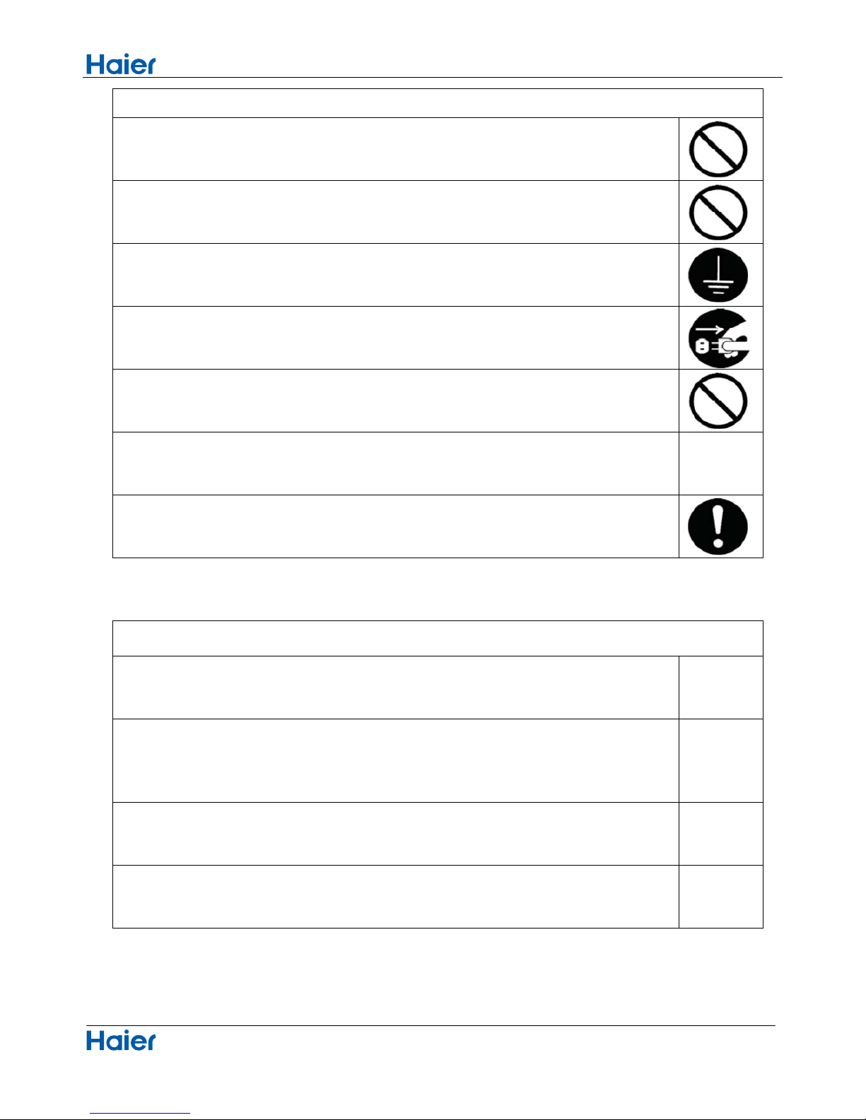
About the pictograms
△ This symbol indicates an item for which caution must be exercised.
The pictogram shows the item to which attention must be paid.
○ This symbol indicates a prohibited action.
The prohibited item or action is shown inside or near the symbol.
● This symbol indicates an action that must be taken, or an instruction.
The instruction is shown inside or near the symbol.
After the repair work is complete, be sure to conduct a test operation to ensure that the equipment operates
Normally, and explain the cautions for operating the product to the customer.
1.2.1 Caution in Repair
Warning
Be sure to disconnect the power cable plug from the plug socket before disassembling the equipment for
a repair.
Working on the equipment that is connected to a power supply can cause an electrical shook.
If it is necessary to supply power to the equipment to conduct the repair or inspecting the circuits, do not
touch any electrically charged sections of the equipment.
If the refrigerant gas discharges during the repair work, do not touch the discharging refrigerant gas .The
refrigerant gas can cause frostbite.
When disconnecting the suction or discharge pipe of the compressor at the welded section, release the
refrigerant gas completely at a well-ventilated place first.
If there is a gas remaining inside the compressor , the refrigerant gas or refrigerating machine oil
discharges when the pipe is disconnected, and it can cause injury.
If the refrigerant gas leaks during the repair work, ventilate the area. The refrigerant gas can generate
toxic gases when it contacts flames.
The step-up capacitor supplies high-voltage electricity to the electrical components of the outdoor unit.
Be sure to discharge the capacitor completely before conducting repair work . A charged capacitor can
cause an electrical shock.
Do not start or stop the air conditioner operation by plugging or unplugging the power cable plug.
Plugging or unplugging the power cable plug to operate the equipment can cause an electrical shock or
fire.
2
Page 5
Intuoduction
Domestic air conditioner
Warning
Do not repair the electrical components with wet hands . Working on the equipment with wet hands can
cause an electrical shock
Do not clean the air conditioner by splashing water. Washing the unit with water can cause an electrical
shock.
Be sure to provide the grounding when repairing the equipment in a humid or wet place, to avoid
electrical
shock.
Be sure to turn off the power switch and unplug the power cable when cleaning the equipment. The
internal fan rotates at a high speed, and cause injury.
Do not tilt the unit when removing it. The water inside the unit can spill and wet the furniture and floor.
Be sure to check that the refrigerating cycle section has cooled down sufficiently before conducting
repair
work. Working on the unit when the refrigerating cycle section is hot can cause burns.
Use the welder in a well-ventilated place. Using the welder in an enclosed room can cause oxygen
deficiency.
1.2.2 Cautions Regarding Products after Repair
Warning
Be sure to use parts listed in the service parts list of the applicable model and appropriate tools to
conduct repair work. Never attempt to modify the equipment. The use of inappropriate parts or tools can
cause an electrical shock, excessive heat generation or fire.
When relocating the equipment, make sure that the new installation site has sufficient strength to
withstand the weight of the equipment.
If the installation site does not have sufficient strength and if the installation work is not conducted
securely, the equipment can fall and cause injury.
Be sure to install the product correctly by using the provided standard installation frame.
Incorrect use of the installation frame and improper installation can cause the equipment to fall, resulting
in injury.
For
integral
units only
Be sure to install the product securely in the installation frame mounted on a window frame.
If the unit is not securely mounted, it can fall and cause injury.
For
integral
units only
3
Page 6
Intuoduction
Domestic air conditioner
Warning
Be sure to use an exclusive power circuit for the equipment, and follow the technical standards related to
the electrical equipment, the internal wiring regulations and the instruction manual for installation when
conducting electrical work.
Insufficient power circuit capacity and improper electrical work can cause an electrical shock or fire.
Be sure to use the specified cable to connect between the indoor and outdoor units. Make the
connections securely and route the cable properly so that there is no force pulling the cable at the
connection terminals.
Improper connections can cause excessive heat generation or fire.
When connecting the cable between the indoor and outdoor units, make sure that the terminal cover
does
not lift off or dismount because of the cable.
If the cover is not mounted properly, the terminal connection section can cause an electrical shock,
excessive heat generation or fire.
Do not damage or modify the power cable.
Damaged or modified power cable can cause an electrical shock or fire. Placing heavy items on the
power cable, and heating or pulling the power cable can damage the cable.
Do not mix air or gas other than the specified refrigerant (R-410A / R22) in the refrigerant system.
If air enters the refrigerating system, an excessively high pressure results, causing equipment damage
and injury.
If the refrigerant gas leaks, be sure to locate the leak and repair it before charging the refrigerant. After
charging refrigerant, make sure that there is no refrigerant leak.
If the leak cannot be located and the repair work must be stopped, be sure to perform pump-down and
close the service valve, to prevent the refrigerant gas from leaking into the room. The refrigerant gas
itself
is harmless, but it can generate toxic gases when it contacts flames, such as fan and other heaters,
stoves and ranges.
.
When replacing the coin battery in the remote controller, be sure to disposed of the old battery to prevent
children from swallowing it.
If a child swallows the coin battery, see a doctor immediately.
4
Page 7
Intuoduction
Domestic air conditioner
Caution
Installation of a leakage breaker is necessary in some cases depending on the conditions of the
installation site, to prevent electrical shocks.
Do not install the equipment in a place where there is a possibility of combustible gas leaks.
If a combustible gas leaks and remains around the unit, it can cause a fire.
Be sure to install the packing and seal on the installation frame properly. If the packing and seal are not
installed properly, water can enter the room and wet the furniture and floor.
1.2.3 Inspection after Repair
Warning
Check to make sure that the power cable plug is not dirty or loose, then insert the plug into a power outlet
all the way.
If the plug has dust or loose connection, it can cause an electrical shock or fire.
If the power cable and lead wires have scratches or deteriorated, be sure to replace them.
Damaged cable and wires can cause an electrical shock, excessive heat generation or fire.
Warning
Do not use a joined power cable or extension cable, or share the same power outlet with other electrical
appliances since it can cause an electrical shock, excessive heat generation or fire.
5
Page 8

Intuoduction
Domestic air conditioner
Caution
Check to see if the parts and wires are mounted and connected properly, and if the connections at the
soldered or crimped terminals are secure. Improper installation and connections can cause excessive
heat generation, fire or an electrical shock.
If the installation platform or frame has corroded, replace it. Corroded installation platform or frame can
cause the unit to fall, resulting in injury.
Check the grounding, and repair it if the equipment is not properly grounded. Improper grounding can
cause an electrical shock.
Be sure to measure the insulation resistance after the repair, and make sure that the resistance is 1 M
ohm or higher.
Faulty insulation can cause an electrical shock.
Be sure to check the drainage of the indoor unit after the repair.
Faulty drainage can cause the water to enter the room and wet the furniture and floor.
1.2.4 Using Icons
Icons are used to attract the attention of the reader to specific information. The meaning of each icon is described in
the table below:
1.2.5 Using Icons List
Icon Type of Information Description
Note
Note
A “note” provides information that is not indispensable, but may
nevertheless be valuable to the reader, such as tips and tricks.
Caution
Caution
A “caution” is used when there is danger that the reader, through
incorrect manipulation, may damage equipment, loose data, get
an
unexpected result or has to restart (part of) a procedure.
Warning
Warning
A “warning” is used when there is danger of personal injury.
Reference
A “reference” guides the reader to other places in this binder or in
this manual, where he/she will find additional information on a
specific topic.
6
Page 9
Specifications
Domestic air conditioner
2.Features
7
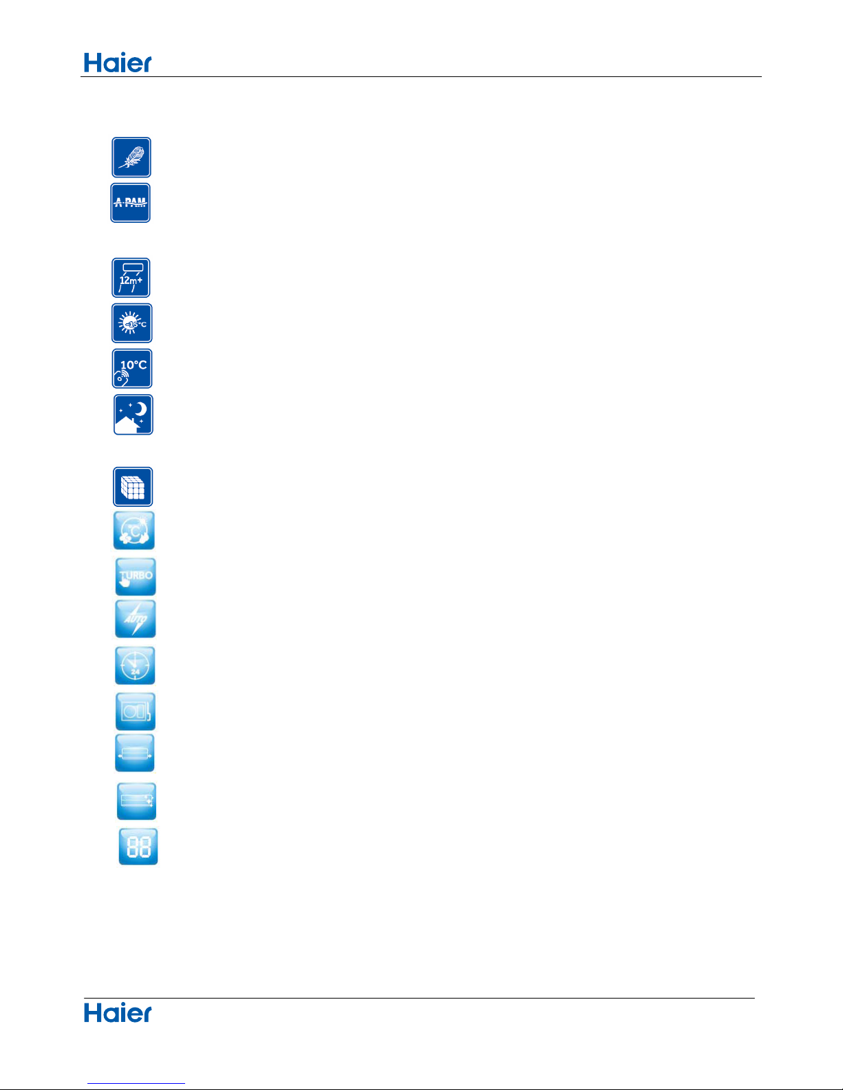
Super quiet: Lower noise operation condition
A-PAM DC inverter:With adoption of S-TYPE,S-PAM and PHASE control technology to works more
stably at low-frequency,and is more energy-saving,mor powerful at high frequency.
Long distance air supplying:
5 F° Heating: When 5 °F can still heating natural
50 °F heating maintenance:Heating Holding 50°F temperature
Confortable sleep:The setting temperature and the indoor noise can be adjusted to a more comfortable
level when you set the “sleep mode” during night sleep.
Super match:One outdoor unit can match two or more indoor unit.
DIY auto mode: Adjust the last fixed operation mode automatically.
Turbo mode: Quick cooling or heating
Auto restart: Automatic return to previous operation conditions after sudden power blackout
24 hours timer: Use the timer function to set on,or off,or from on to off,or from off to on.
Intergr
ative valve cover:The valve cover is Intergrative.
2-way piping design: The pipe can shoot out both from left or right side.
Easy clean design: The panel is easy to wash and the airflow vents can be detached easily
Double 8 display:The display is Double 8 mode.
Page 10
Specifications
Domestic air conditioner
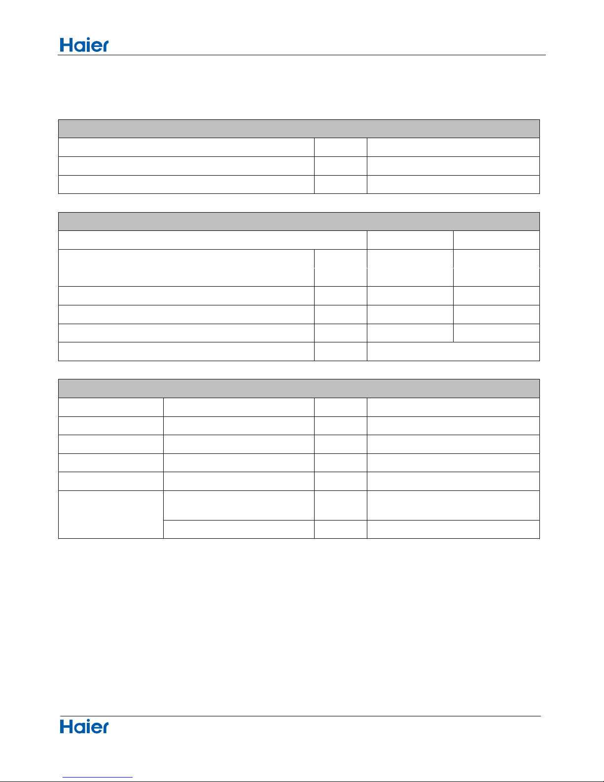
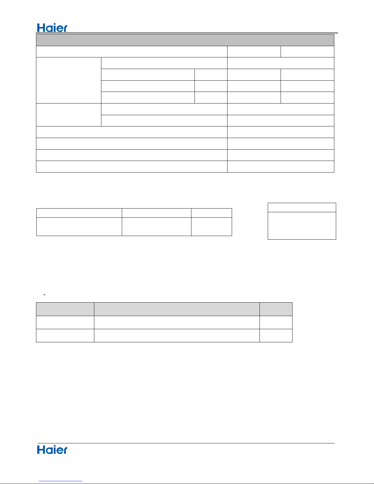
3 Specifications
NOMINAL DISTRIBUTION SYSTEM VOLTAGE
1/esahP
05zHycneuqerF
032VegatloV
NOMINAL CAPACITY and NOMINAL INPUT
cooling heating
Capacity rated
Btu/h
17000(4780-13300) 18000(5120-13990)
Power Consumption(Ra 50685222Btu)det
38/BtuBtuPOC/REE
hWKnoitpmusnocygrenelaunnA 999950 6252250
h/³inlavomeRerutsioM 70.62*10 ³
TECHNICAL SPECIFICATIONS
1.06×0.77×3.21inD*W*HsnoisnemiD
1.32×1.08×3.56inD*W*HsnoisnemiDdegakcaP
28.6lb/thgieW
35.2lb/thgiewssorG
etihW//roloC
Sound level
Sound
peessure(high/medium/low)
dB
Sound power(high) dB
8
-
57/54/51
38
/
Page 11
Specifications
Domestic air conditioner
TECHNICAL SPECIFICATIONS-PARTS
cooling heating
Fan
nafwolfssorCepyT
136.5WtuptuorotoM
Air flow rate(high) in³/h 31779 31779
Speed(high/middle/low) rpm 950/850/750 900/ 800/700
Heat exchanger
Type
ML fin-φ7HI-HX tube
4.1*81*3hctif*egats*tnemgeS
hgiRlortnocnoitceridriA t,Left,Horizontal,Downward
Air filter
Removable/Washable/Mildew Proof
Temperature control
Microcomputer Control
HD01-RYledomrellortnocetomeR
Note: the data are based on the conditions shown in the table below
htgnelgnipiPgnitaehgnilooc
16.4in
4.Sensors list
type Description Qty
1erutarepmetmoorgnitcetedrofdesustIrosnesmooR
Pipe sensor Its used for detecting temperature of evaporator 1
Conversation formulae
Kcal/h= KW×860
Btu/h= KW×3414
cfm=m³/min×35.3
9
136.5
Indoor:
80.6°
F
DB/66.2°
F
W B
Outdoor: 95°
F
DB/75.2°FW B
Indoor:68°
F
D B
Ou t doo r: 44.6°
F
D B / 42.8°
F
W B
Page 12
Piping diagrams
Domestic air conditioner
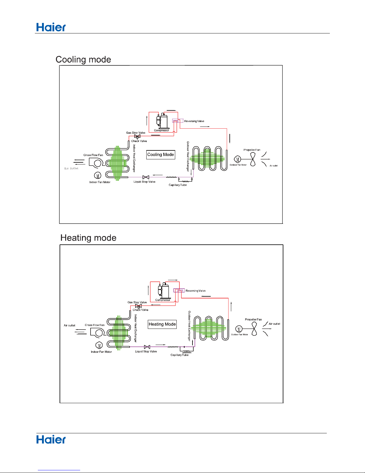
5.Pinping diagrams
10
Page 13
Connector Wiring diagrams
Domestic air conditioner
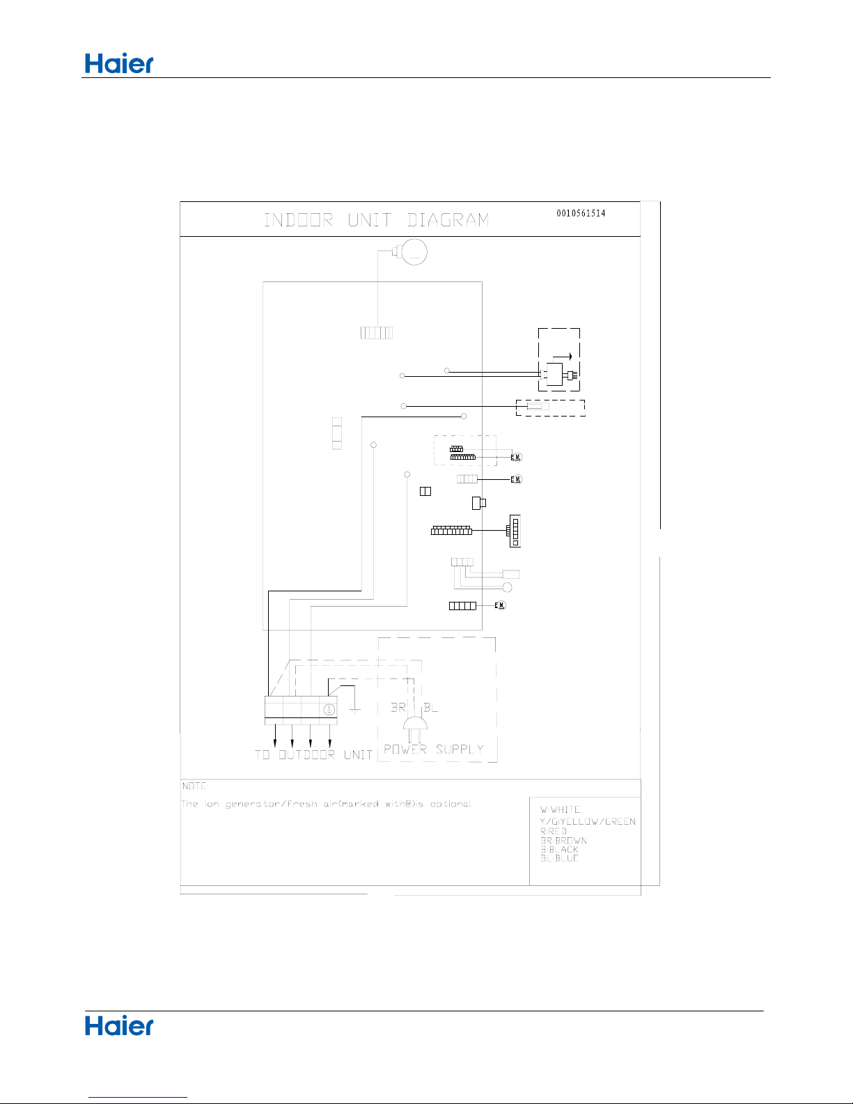
6. Printed Circuit Board Connector Wiring Diagram
11
Connectors
PCB(1) (Control PCB)
daolhtiwtcennoC
rotcennocBCPseires
1 CN9
Connector for fan motor
2 CN6
Connector for heat exchanger thermistor and Room temperature thermistor
3
CN5
Connector for UP&DOWN STEP motor
4 CN21
Connector for power N wire
5 CN52
Connector for power L
6 CN27
7 CN7
8 CN23 Connector for communicate between the indoor board and the outdoor board
9 CN34
Connector for power GRN
Connector for display board
Note: Other designations
PCB(1) (Indoor Control PCB)
1) CN14 Connector for Forced operation ON / OFF switch
2) SW2 1 Select remote code A or B,2 Select room card able or disable , 3-4 Select 23,26,33,or 35
3) RV1 Varistor
4) FUSE1 Fuse 3.15A/250VAC
Connector for long-range control
Page 14

Connector Wiring diagrams
Domestic air conditioner
12
PCB(1)
C23
CN21
CN7
CN14
CN6
CN52
CN34
CN9
CN5
CN27
Page 15
Connector Wiring diagrams
Domestic air conditioner
Wiring diagrams
13
up-down stepmoter
ION GENERATIOR
Y/G
C0N2
C0N3
DC FAN MOTOR
M
FUSE1
SW1
EMERGENCY SWITCH
RECEIVER
DISPLAY
CN7
T3.15A/250V AC
80
120
1
(N)
(C)
3
(L)
2
W
B
Y/G
Y/G
GND
CN14
AMBIENT TEMP SENSOR
PIPING TEMP SENSOR
CN6
CN10
Right stepmoter
left stepmoter
CN11
CN5
CN5-1 CN5-2
R
C0N1
BL
Fresh air
(L)
CN21
N
S
CN51
Room card
R
W
@
@
CN9
CN52
CN23
Page 16
Functions and Control
Domestic air conditioner
7.Funcitions and Control
7.1 Main functions and control specification
7.1.1 Automatic operation
When the running mode is turned to automation after starting the system, the system will first determine
the running mode according to the current room temperature and then will run according to the determined
mode. Tr in the following selection conditions means room temperature, Ts means setting temperature, Tp
means temperature of indoor coil pipe
Tr 73.4°F Choose Cooling Mode
Tr
Choose Heating Mode
After turning to the automation mode, the running mode can be switched between cooling mode, fan
mode and heating mode according to the change of the indoor ambient temperature. But the automatic
conversion between cooling mode and heating mode must be conducted after 15 minutes.
7.1.2 Cooling operation mode
Temperature control range: 60.8°F---86°F
Temperature difference: 33.8°F/30.2°F
* Control features: When Tr
input airflow >Ts set temperature °F, the compressor will be opened, the indoor
fan will operate at the set speed and the mode signal will be sent to the outdoor system. When Tr
input
airflow
Ts set temperature °F, the compressor will be opened, the indoor fan will operate at the set speed
and the mode signal will be sent to the outdoor system. The system will keep the original status if Tr= Ts.
Airflow speed control: (temperature difference 33.8°F)
Automatic: When Tr
Ts+37.4°F, high speed.
When Ts+33.8°F
Tr<Ts+37.4°F, medium speed
When Tr<Ts+33.8°F , low speed
When the sensor is off, low speed
When the airflow speed has no delay from the high to low switching, the speed should be delayed for 3
minutes (remain at high speed for 3 minutes.) before the next switch.
Manus: When the system is operating, you can set the high, medium or low speed manually. (When the
sensor is on or off, the system will change the speed 2 seconds after receiving the signal.)
*Airgate location control: the location for the airgate can be set according to your needs.
*Defrosting function: preventing the frosting on the indoor heat exchanger (when cooling or dehumidifying).
When the compressor works continuously for 1/6 minutes (adaptable in EEPROM) and the temperature of
the indoor coils has been below zero centigrade
for 10 seconds, the compressor will be stopped and the
malfunction will be recorded in the malfunction list. The indoor system will continue to run. When the
temperature of the indoor coil is raised to 46°F, the compressor will be restarted again (the requirement of 3
minutes’ delay should be satisfied.)
* timing system on/off function.
* Dormant control function.
14
73.4°F
Page 17
Functions and Control
Domestic air conditioner
7.1.3 Dehumidifying mode.
* temperature control range:
60.8---86 F
* temperature difference:
30.2/33.8°F
Control feature: send the dehumidifying signal to the outdoor system.
When Tr>Ts+35.6°F , the compressor will be turned on, the indoor fan will operate at the set speed.
When Tr is between the Ts and Ts+35.6°F , the outdoor system will operate at the high dehumidifying
frequency for 10 minutes and then at the low dehumidifying mode for six minutes. The indoor fan will
operate at low speed.
When Tr< Ts, the outsystem will be stopped, the indoor fan will be stopped for 3 minutes and then turned to
the low speed option.
All the frequency converses have a 30.2/33.8°F difference.
* Wind speed control: Automatic:
When Tr
Ts+41°F , high speed.
When Ts+37.4°F Tr< Ts+41°F , medium speed.
When Ts+35.6°F Tr< Ts+37.4°F, low speed.
When Tr<Ts+35.6°F, light speed.
If the outdoor fan stopped, the indoor fan will be paused for 3 minutes.
If the outdoor fan stopped for more than 3 minutes and the outdoor system still operates, the system will be
changed into light speed mode.
When the airflow speed has no delay from the high to low switching, the speed should be delayed for 3
minutes (remain at high speed for 3 minutes.) before the next switch.
Manual: When the sensor is off or Tr< Ts+37.4°F, the manual operation can not be made. (obligatory automatic
operation.)
*Airgate location control: the location for the airgate can be set according to your needs.
*Defrosting function: preventing the frosting on the indoor heat exchanger (when cooling or dehumidifying).
When the compressor works continuously for 1/6 minutes (adaptable in EEPROM) and the temperature of
the indoor coils has been below zero centigrade for 10 seconds, the compressor will be stopped and the
malfunction will be recorded in the malfunction list. The indoor system will continue to run. When the
temperature of the indoor coil is raised to 44.6°F, the compressor will be restarted again (the requirement of 3
minutes’ delay should be satisfied.)
* Coil protection (synchronic overheating protection) are installed for the four directions latch malfunctions
when dehumidifying.
* Timing system on/off function.
* Dormant control functio
n.
7.1.4 Heating operation mode.
*
temperature control range: 60.8---86 F
* temperature difference: 30.2/33.8°F
* control feature: the temperature compensation is automatically added and the system will send the heating
signals to the outdoor system.
If Tr
Ts, the outdoor compressor is turned on, the indoor fan will be at the cold air proof mode.
If Tr>Ts+35.6°F, the outdoor system is turned off, the indoor fan will be at the heat residue sending mode.
If Tr<Ts+35.6°F, the outdoor system will be turned on again, the indoor fan will be at the cold air proof mode.
15
<
<
Page 18
Functions and Control
Domestic air conditioner
*Indoor fan control
manual control: You can choose high, medium, low and automatic speed control.
Automatic: When Tr<Ts, high speed.
When Ts
Tr Ts+35.6°F, medium speed.
When Tr> Ts+35.6°F, low speed.
When the airflow speed has no delay from the high to low switching, the speed should be delayed for 3
minutes (remain at high speed for 3 minutes.) before the next switch.
*Airgate location control: the location for the airgate can be set according to your needs.
Coldair proof operation
1. The indoor operation within 4 minutes after the start up is as the following diagram, the air speed can be
raised only after the speed has reached a certain level.
2. 4 minutes after the start up of the indoor fan, the light airflow and the low airflow will be turned to the set
speed airflow.
3. In the cold air proof operation, the fan won’t stop after the start up.
4. During the cold air proof operation, the indoor system will continuously send ‘indoor high speed’ signals to
the outdoor system.
* Resi
due heat sending. The indoor fan will send the residue heat at a low speed for 12 seconds.
If other conditions are satisfied, when the compressor stops, the indoor system will operate at a light speed.
The indoor fan will stop when the coil temperature is below the ‘heat start temp 4’.
* Defrosting. When the system receives the defrosting signal from outdoors, the indoor fan will stop and the
indoor temperature display won’t change. At the time, any indoor coil malfunctions will be neglected. When
the outdoor defrosting finishes, the coil malfunction will still be neglected until the compressor has been
started up for 30 seconds. The indoor temperature display will not change and the system operates at the
cold air proof mode.
* Automatic heating temperature compensation: when the system enters the heating mode, the temperature
compensation (4) will be added. When the status is switched off, the compensation will be erased.
7.1.5 Strength operation
The system enters the mode after receiving the ‘strength signal’.
Send strength operation signal to the outdoor system.
The mode change finishes the strength operation.
Entering ‘mute’, you can have normal operation or signal control such as timing to finish the strength
operation.
When the system is at the automatic option with the strength/ mute function, if the system enters the cooling
Heat start temp 1
Heat start temp
2
Heat start temp
3
Heat start temp
4
Set speed
Low speed
Light speed
Fan/off
Fan/off
Keep the hig
h
speed. The fa
n
doesn’t stop
16
Page 19
Functions and Control
Domestic air conditioner
mode, the cooling strength/ mute function will be offered; if the system enters the heating mode, then the
heating strength/ mute function will be offered; if the system enters the airflow mode, there will be no
strength/ mute function.
7.1.6 Mute operation
The system enters the mode after receiving the ‘mute signal’.
a. Mute heating: the airflow speed is slight, the system sends the mute signal to the outdoor system.
b. mute cooling: the airflow speed is slight, the system sends the mute signal to the outdoor system.
When the compressor operates, the airflow speed is mute speed. EEPROM is adaptable.
Mute operation can not work under the dehumidifying and airflow-sending operation.
7.1.7 Air refreshing
After receiving the signal from the remote control, (HV series: the background light of the ‘health’ logo is
green. HS series: the ‘health’ indicator will be lighted). If the fan operates, the Nano-Aqua operates to realize
the ions sending function.
If the indoor fan stops, the Nano-Aqua is turned off.
When the Nano-Aqua is turned off, if the air refreshing system is turned on, the Nano-Aqua will be turned on
when the fan operates.
7.1.8 Timing
You can set 24 hours’ on/off timing accordingly. After the setting, the timing indicator will be lightened. Also,
the light will be turning off after the timing is finished. The followings are several timing methods.
1.system /on timing: The timing indicator will be lightened and the indoor system is under the waiting mode.
The light will be turned off when the timing is finished and the rest of the system will operate under a normal
condition. The timing starts since the last reception of the timing signal.
2.system /off timing: When the system is turned on, the timing indicator is lightened, the rest of the system
will operated under a normal condition. When set time comes, the indicator light will be turned off and the
system will be turned off. If you have set the dormant functions, the order of your settings will be operated
according to the timing settings.
3 .system /on and off timing: The settings will be completed according to the orders..
7.1.9 Dormant operation
The dormant timing is an eight hours unadaptable one. The timing signs are shown on the V series board.
(RC series show the dormant signal, the timing light is lighted on the 6 lights board).
2.1 Under the cooling/ dehumidifying operation, after the setting of the dormant operation, the set
temperature will be raised for 1 centigrade after 1 hour’s operation and will be raised for 1 centigrade 1 hour
later. The system will keep this status for 6 hours and then close.
2.2 Under the heating mode, after the setting of the dormant operation, the setting temperature will fall 2
centigrade after 1 hour’s operation and will fall 2 centigrade 1 hour later. 3 hours after the preceding
operations, the set temperature will be raised for 1 centigrade and the system will keep this status for 3 hours
and then close down.
2.3 During the dormant time, except the change of the system mode or a new press on the dormant setting
17
Page 20

Functions and Control
Domestic air conditioner
keys, the timing of the 8 hours dormancy will take the first timing as the start time, any presses on other keys
will not affect the original timing.
2.4 Indoor fan control under the dormant operation.
If the indoor fan is at the high speed before the dormant operation setting, the speed will be turned to medium
after the setting. If the fan is at the medium speed before the dormant setting, the speed will be turned to low
after the setting. If the fan is at the low speed before the dormant setting, the speed will not change.
7.1.10 Urgent on/off input
Press the urgency button the buzzer will ring. The system will enter the automatic mode if you don’t press the
button for more than 5 seconds.
Under the system off mode, if you press the urgency key for 5 to 10 seconds, the system will start the test
operation.
Under the system off mode, if you press the urgency key for 10 to 15 seconds, the
display screen will show
the resume of the last malfunction.
If the system is under operation, the press on the urgency key will stop it.
Under the system off mode, the display screen will show automatic running sign.
Under the system off mode, the system will not receive the remote control signal if the press on the urgency
key doesn’t last for 15 seconds or if the key is loosened.
Urgency operation: If you press the urgency key for less than 5 seconds, the buzzer will ring when you press
the on/off key. The system will enter the urgency operation when the urgency key is loosened. The urgency
operation is fully automatic.
Test operation.
The inlet temperature sensor doesn’t work, the indoor fan and the indoor air direction board motor works
synchronically. High speed airflow, cooling, outdoor system on, etc, will send the ambient temperature 30
centigrade and coil temp
erature 16 centigrade information to the outdoor system.
Test operation
The defrost protection of the evaporator doesn’t work.
The temperature control doesn’t work.
The test operation will be finished in 30 minutes.
The test operation can be stopped by the relative commands from the remote control.
7.1.11 Low load protection control
In order to prevent the frosting of the indoor heat interaction device, the outdoor system will be stopped if the
indoor heat interaction temperature is below zero centigrade for 5 minutes, but the fan will continue to
operate. The outdoor system will be started again when the heat interaction temperature is above 7
centigrade and the system has been stopped for 3 minutes. The malfunction will be stored in the malfunction
resume and will not be revealed.
7.1.12 High load protection control
The outdoor system will be stopped if the coil temperature is above 149°F for 2 minutes. The indoor fan will be
controlled by the thermostat. The outdoor system can be restarted when the coil temperature is below 107.6°F
and the system has been stopped for 3 minutes. The malfunction will be stored in the malfunction resume
18
Page 21

Functions and Control
Domestic air conditioner
and will not be revealed.
7.1.13 Abnormal operation of indoor system
When the outdoor system operates, if the indoor system operation differs from the outdoor system, the
abnormal operation malfunction will be reported. 10s after the report, the indoor system will be closed.
Outdoor system mode Indoor system mode conflicts
cooling heating yes
cooling cooling no
cooling airflow no
heating heating no
heating airflow yes
heating cooling yes
7.1.14 Malfunction list resume.
Nothing is presented if there is no code list.
The malfunction display will automatically finish in 10 seconds.
The remote control only receives the signals for stop. According to the signals, the malfunction resume
presentation finishes.
The resume restores after the power supply restores.
7.1.15 Abnormality confirmation approaches
1. indoor temperature sensor abnormality:
Under the operation, the normal temperature ranges from 248°F to -22°F. When the temperature
goes beyond this range, the
abnormality can be confirmed. If the temperature goes back into the range, the
system will automatically resume.
2 .indoor heat interaction sensor abnormality:
Under the operation, the normal temperature ranges from 248°F to -22°F. When the temperature
goes beyond this range, the abnormality can be confirmed. If the temperature goes back into the range, the
system will automatically resume.
3 .indoor malfunction:
Out door malfunction: When the indoor system receives the outdoor malfunction codes, it will store the code
into E2 for the malfunction list resume. The indoor system will continue to operate according to the original
status, the malfunction code will not be revealed or processed.
4. transmission abnormality:
If the indoor system can’t receive the outdoor system for 8 minutes, the communication abnormality can be
confirmed and reported and the outdoor system will be stopped.
7.1.16 Single indoor system operation
* Enter condition: First, set the high speed airflow and 86°F set temperature, then press the dormant
keys for 6
times within 7 seconds, the system will feedback with 6 rings.
* After the system enters the separate indoor system operation mode, the indoor system will operate
19
Page 22

Functions and Control
Domestic air conditioner
according to the set mode and neglect the communication signals of the outdoor system. However, it has to
send signals to the outdoor system.
* Quitting condition: This mode can be quitted after receiving the quitting signal from the remote control or
urgency system. The indoor system thus can quit the single operation mode.
7.1.17 Power cut compensation
* Entering condition: Press dormant button 10 times within 7 second, the buzzer will ring 4 times and the
present system status will be stored into the EEPROM of the indoor system.
* After entering the power cut compensation mode, the processing of the indoor system should be as the
followings:
Remote control urgency signal: operate according to the remote control and the urgent conditions, the
present status will be stored into the EEPROM of the indoor system.
* Quitting conditions: Press dormant button 10 times within 7 seconds and the buzzer will ring twice.
7.1.18 Fixed frequency operation
1. Fixed cooling: a. under G code condition: high speed cooling, set 60.8°F , press temperature ‘-‘ key and the
set key at the same time. The system will enter the fixed frequency operation after the buzzer rings twice.
b. The proceeding programs are as the follows:
Entering the fixed frequency operation, you can set the fixed strength location 1 and send the cooling signal
to the outdoor system. Meanwhile, you can fix the indoor system at high speed mode, the location of the
airflow direction board can be switched to the maximal position.
c. Quitting condition: The fixed frequency cooling can be quitted after receiving the remote signal, and the
system will enter the remote setting status.
2. Fixed heating: a. under G code condition: high speed heating, set 86°F, press temperature ‘+‘ key and the
set key at the same time. The system will enter the fixed frequency operation after the buzzer rings twice.
b. The proceeding p
rograms are as the follows:
Entering the fixed frequency operation, you can set the fixed strength location 1 and send the heating signal
to the outdoor system. Meanwhile, you can fix the indoor system at high speed mode, the location of the
airflow direction board can be switched to the maximal position.
c. Quitting condition: The fixed frequency heating can be quitted after receiving the remote signal, and the
system will enter the remote setting status.
7.1.19 Test program
First, connect the test program terminal on the mainboard. Then connect the system to the power circuit. The
test program will operate as follows.
HV series display: The buzzer rings for one time—the signal will be sent to outdoor system for 0.5 second—
the violet is sent for 0.5-- the background light turns to white—the back ground light turns to white—the
background light turns to white—the background li
ght is fully lighted for 0.5 second—LED screen lights for
0.5 second— the step-in motor fully output for 0.5 second—then the motor doesn’t output for 0.5
second—the motor fully output again for 0.5 second. The test program finishes.
20
Page 23
Functions and Control
Domestic air conditioner
7.1.20 Time cutting function:
Connect the test program terminal on the mainboard after connecting the system to the power circuit. The
CPU of the main control will be 60 times faster.
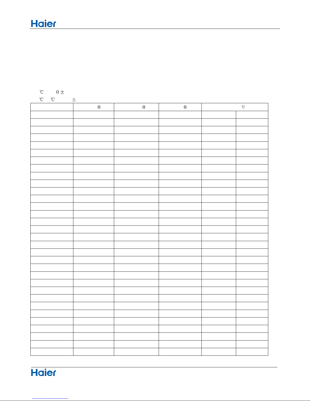
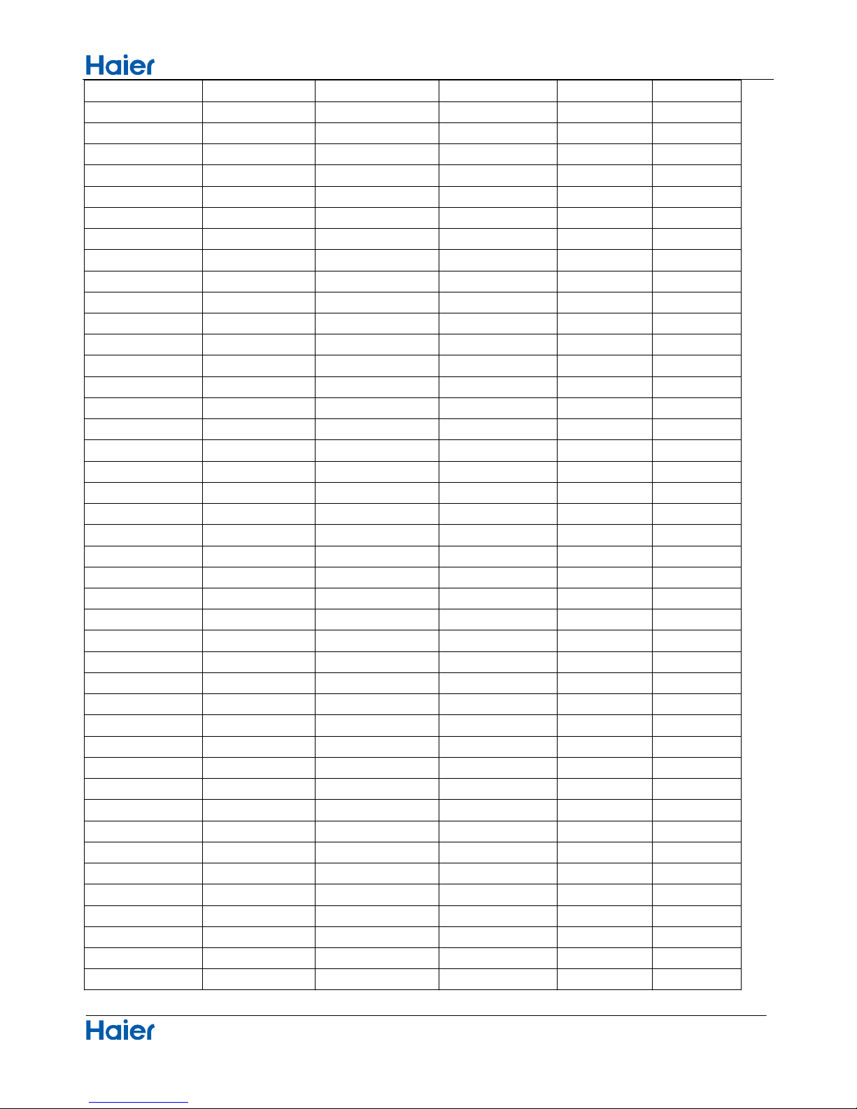
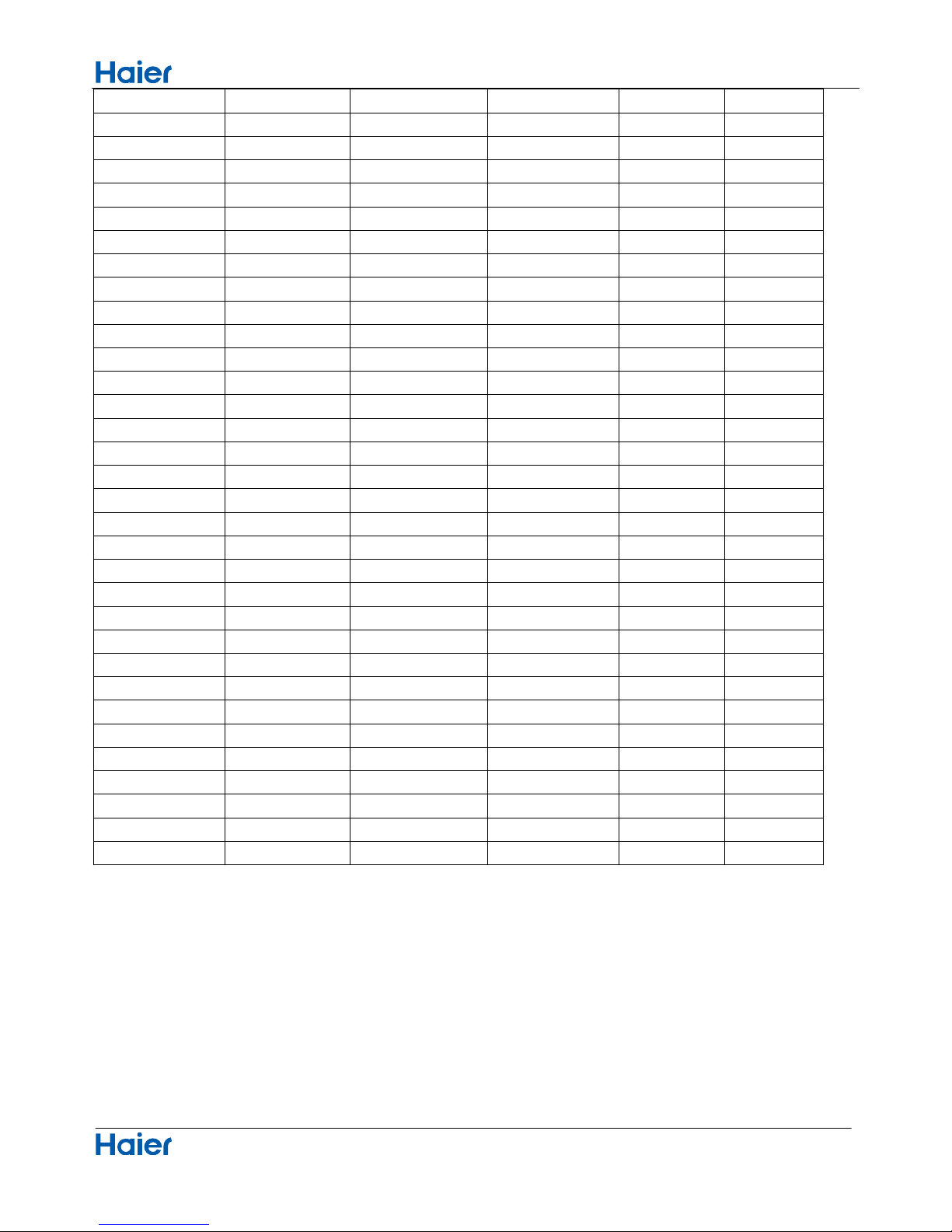
7.2 Value of thermistor
Room sensor and Pipe Sensor
R25 =10K 3%
B25
/50 =3700K 3%
Temp.(( °F ))
Max.(K
) Normal(K ) Min.(K )
Tolerance(
)
-22 165.2170 147.9497 132.3678 28.51 35.15
-20.2 155.5754 139.5600 125.0806 28.53 35.13
-18.4 146.5609 131.7022 118.2434 28.56 35.11
-16.6 138.1285 124.3392 111.8256 28.60 35.08
-14.8 130.2371 117.4366 105.7989 28.63 35.06
-13 122.8484 110.9627 100.1367 28.67 35.04
-11.2 115.9272 104.8882 94.8149 28.71 35.01
-9.4 109.4410 99.1858 89.8106 28.74 34.99
-7.6 103.3598 93.8305 85.1031 28.76 34.95
-5.8 97.6556 88.7989 80.6728 28.80 34.93
-4 92.3028 84.0695 76.5017 28.83 34.92
-2.2 87.2775 79.6222 72.5729 28.87 34.88
-0.4 82.5577 75.4384 68.8710 28.90 34.86
-1.4 78.1230 71.5010 65.3815 28.94 34.83
-3.2 73.9543 67.7939 62.0907 28.98 34.79
-5 70.0342 64.3023 58.9863 29.01 34.77
-6.8 66.3463 61.0123 56.0565 29.05 34.74
-8.6 62.8755 57.9110 53.2905 29.08 34.72
-10.4 59.6076 54.9866 50.6781 29.12 34.68
-12.2 56.5296 52.2278 48.2099 29.16 34.65
-14 53.6294 49.6244 45.8771 29.19 34.63
15.8 50.8956 47.1666 43.6714 29.23 34.59
17.6 48.3178 44.8454 41.5851 29.28 34.56
19.4 45.8860 42.6525 39.6112 29.32 34.52
21.2 43.5912 40.5800 37.7429 29.35 34.50
23 41.4249 38.6207 35.9739 29.39 34.47
24.8 39.3792 36.7676 34.2983 29.43 34.43
26.6 37.4465 35.0144 32.7108 29.46 34.39
28.4 35.6202 33.3552 31.2062 29.52 34.36
30.2 33.8936 31.7844 29.7796 29.55 34.32
32 32.2608 30.2968 28.4267 29.59 34.30
33.8 30.7162 28.8875 27.1431 29.62 34.27
21
Page 24

Functions and Control
Domestic air conditioner
35.6 29.2545 27.5519 25.9250 29.68 34.23
37.4 27.8708 26.2858 24.7686 29.71 34.20
39.2 26.5605 25.0851 23.6704 29.75 34.16
41 25.3193 23.9462 22.6273 29.79 34.12
42.8 24.1432 22.8656 21.6361 29.84 34.09
44.6 23.0284 21.8398 20.6939 29.88 34.05
46.4 21.9714 20.8659 19.7982 29.93 34.02
48.2 20.9688 19.9409 18.9463 29.97 33.96
50 20.0176 19.0621 18.1358 30.00 33.93
51.8 19.1149 18.2270 17.3646 30.06 33.89
53.6 18.2580 17.4331 16.6305 30.09 33.85
55.4 17.4442 16.6782 15.9315 30.15 33.82
57.2 16.6711 15.9601 15.2657 30.18 33.78
59 15.9366 15.2770 14.6315 30.24 33.73
60.8 15.2385 14.6268 14.0271 30.27 33.69
62.6 14.5748 14.0079 13.4510 30.33 33.66
64.4 13.9436 13.4185 12.9017 30.36 33.62
66.2 13.3431 12.8572 12.3778 30.42 33.57
68 12.7718 12.3223 11.8780 30.45 33.53
69.8 12.2280 11.8126 11.4011 30.51 33.49
71.6 11.7102 11.3267 10.9459 30.54 33.44
73.4 11.2172 10.8634 10.5114 30.60 33.40
75.2 10.7475 10.4216 10.0964 30.65 33.35
77 10.3000 10.0000 9.7000 30.65 33.35
78.8 9.8975 9.5974 9.2980 30.63 33.37
80.6 9.5129 9.2132 8.9148 30.56 33.34
82.4 9.1454 8.8465 8.5496 30.49 33.49
84.2 8.7942 8.4964 8.2013 30.43 33.55
86 8.4583 8.1621 7.8691 30.36 33.62
87.8 8.1371 7.8428 7.5522 30.29 33.67
89.6 7.8299 7.5377 7.2498 30.24 33.75
91.4 7.5359 7.2461 6.9611 30.16 33.80
93.2 7.2546 6.9673 6.6854 30.09 33.87
95 6.9852 6.7008 6.4222 30.02 33.93
96.8 6.7273 6.4459 6.1707 29.97 34.00
98.6 6.4803 6.2021 5.9304 29.89 34.05
100.4 6.2437 5.9687 5.7007 29.82 34.12
102.2 6.0170 5.7454 5.4812 29.75 34.20
104 5.7997 5.5316 5.2712 29.68 34.25
105.8 5.5914 5.3269 5.0704 29.61 34.32
107.6 5.3916 5.1308 4.8783 29.53 34.39
109.4 5.2001 4.9430 4.6944 29.46 34.45
111.2 5.0163 4.7630 4.5185 29.39 34.52
22
Page 25
Functions and Control
Domestic air conditioner
113 4.8400 4.5905 4.3500 29.32 34.59
114.8 4.6708 4.4252 4.1887 29.25 34.65
116.6 4.5083 4.2666 4.0342 29.17 34.72
118.4 4.3524 4.1145 3.8862 29.10 34.79
120.2 4.2026 3.9686 3.7443 29.03 34.86
122 4.0588 3.8287 3.6084 28.94 34.92
123.8 3.9206 3.6943 3.4780 28.87 34.99
125.6 3.7878 3.5654 3.3531 28.80 35.06
127.4 3.6601 3.4416 3.2332 28.72 35.13
129.2 3.5374 3.3227 3.1183 28.63 35.20
131 3.4195 3.2085 3.0079 28.56 35.28
132.8 3.3060 3.0989 2.9021 28.49 35.33
134.6 3.1969 2.9935 2.8005 28.40 35.40
136.4 3.0919 2.8922 2.7029 28.33 35.47
138.2 2.9909 2.7948 2.6092 28.26 35.55
140 2.8936 2.7012 2.5193 28.17 35.62
141.8 2.8000 2.6112 2.4328 28.09 35.69
143.6 2.7099 2.5246 2.3498 28.00 35.76
145.4 2.6232 2.4413 2.2700 27.93 35.83
147.2 2.5396 2.3611 2.1932 27.84 35.91
149 2.4591 2.2840 2.1195 27.75 35.98
150.8 2.3815 2.2098 2.0486 27.68 36.05
152.6 2.3068 2.1383 1.9803 27.59 36.12
154.4 2.2347 2.0695 1.9147 27.52 36.21
156.2 2.1652 2.0032 1.8516 27.43 36.28
158 2.0983 1.9393 1.7908 27.34 36.36
159.8 2.0337 1.8778 1.7324 27.27 36.43
161.6 1.9714 1.8186 1.6761 27.18 36.50
163.4 1.9113 1.7614 1.6219 27.09 36.57
165.2 1.8533 1.7064 1.5697 27.00 36.64
167 1.7974 1.6533 1.5194 26.91 36.73
168.8 1.7434 1.6021 1.4710 26.82 36.81
170.6 1.6913 1.5528 1.4243 26.74 36.88
172.4 1.6409 1.5051 1.3794 26.65 36.95
174.2 1.5923 1.4592 1.3360 26.56 37.04
176 1.5454 1.4149 1.2942 26.47 37.11
177.8 1.5000 1.3721 1.2540 26.38 37.18
179.6 1.4562 1.3308 1.2151 26.29 37.27
181.4 1.4139 1.2910 1.1776 26.20 37.35
183.2 1.3730 1.2525 1.1415 26.11 37.42
185 1.3335 1.2153 1.1066 26.02 37.51
186.8 1.2953 1.1794 1.0730 25.92 37.58
188.6 1.2583 1.1448 1.0405 25.83 37.67
23
Page 26
Functions and Control
Domestic air conditioner
190.4 1.2226 1.1113 1.0092 25.74 37.74
192.2 1.1880 1.0789 0.9789 25.65 37.83
194 1.1546 1.0476 0.9497 25.56 37.90
195.8 1.1223 1.0174 0.9215 25.45 37.99
197.6 1.0910 0.9882 0.8942 25.36 38.07
199.4 1.0607 0.9599 0.8679 25.27 38.16
201.2 1.0314 0.9326 0.8424 25.16 38.23
203 1.0030 0.9061 0.8179 25.07 38.32
204.8 0.9756 0.8806 0.7941 24.98 38.39
206.6 0.9490 0.8558 0.7711 24.87 38.48
208.4 0.9232 0.8319 0.7489 24.78 38.55
210.2 0.8983 0.8088 0.7275 24.67 38.64
212 0.8741 0.7863 0.7067 24.58 38.73
213.8 0.8507 0.7646 0.6867 24.48 38.80
215.6 0.8281 0.7436 0.6672 24.39 38.89
217.4 0.8061 0.7233 0.6484 24.28 38.98
219.2 0.7848 0.7036 0.6303 24.19 39.06
221 0.7641 0.6845 0.6127 24.08 39.15
222.8 0.7441 0.6661 0.5957 23.97 39.24
224.6 0.7247 0.6482 0.5792 23.88 39.33
226.4 0.7059 0.6308 0.5632 23.77 39.42
228.2 0.6877 0.6140 0.5478 23.67 39.49
230 0.6700 0.5977 0.5328 23.56 39.58
231.8 0.6528 0.5820 0.5183 23.47 39.67
233.6 0.6361 0.5667 0.5043 23.36 39.76
235.4 0.6200 0.5518 0.4907 23.25 39.85
237.2 0.6043 0.5374 0.4775 23.14 39.94
239 0.5891 0.5235 0.4648 23.04 40.01
240.8 0.5743 0.5100 0.4524 22.93 40.10
242.6 0.5600 0.4968 0.4404 22.82 40.19
244.4 0.5460 0.4841 0.4288 22.71 40.28
246.2 0.5325 0.4717 0.4175 22.60 40.37
248 0.5194 0.4597 0.4066 22.50 40.46
24
Page 27
System configuration
Domestic air conditioner
8 System configuration
8.1System configuration
After the installation and test operation of the room air conditioner have been completed, it should be
operated and handled as described below. Every user would like to know the correct method of operation
of the room air conditioner, to check if it is capable of cooling(or heating) well, and to know a clever method
of using it. In order to meet this expectation of the users, giving sufficient explanations taking enough time
can be said to reduce about 80% of the requests for servicing. However good the installation work is and
however good the functions are, the customer may blame either the room air conditioner or its installation
work because of improper handling. The installation work and handing over of the unit can only be
considered to have been completed when its handling has been explained to the user without using
technical terms but giving full knowledge of the equipment.
8.2 Instruction
25
Page 28
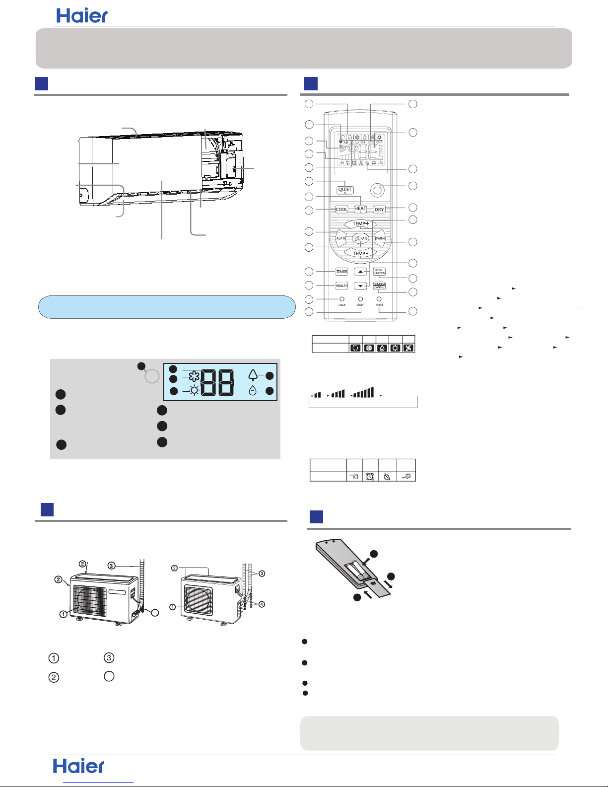
Display board
Signal receiver hole
COOL display
HEALTH display
4
2
3
1
5
DRY display
6
Ambient temp.display
When receiving the remote
control signal, display the set
temperature.
2
3
5
6
4
HEAT display
1
Outlet
Horizontal flap
Display board
(adjust up and down air flow
Don't adjust it manually)
(adjust left and
ow)
Vertical blade
Emergency
Switch
right air fl
Inlet
Air Purifying Filter
(inside)
Inlet grille
Anion generator
(inside)
(inside)
Actual inlet grille may vary from the one shown in the
manual according to the product purchased
The unit pictured above is for reference only.
Your product may appear different.
4
Outdoor Unit
4
Inserting the Battery
Parts and Functions
Indoor Unit
OUTLET
INLET
CONNECTING PIPING AND ELECTRICAL WIRING
DRAIN HOSE
Remote Control
Hint:
Remove the batteries if the unit won't be in use for a long period. If
there is any display after taking-out the batteries, just press reset key.
1. Mode display
2. Signal sending display
4. FAN SPEED display
5. LOCK display
6. TIMER OFF display
TIMER ON display
LO MED HI
7.TEMP display
16. LOCK button
Used to lock buttons and LCD display.
25. RESET button
If the remote is not functioning properly,
use a pen point or similar object to
depress the button to reset the remote
22. HOUR button
Operation mode
NAFOTUA COOL DRY
Remote controller
HEAT
1
2
3
4
5
9
10
11
12
13
14
15
16
17
22
23
24
25
19
20
21
8
18
7
6
Control the lightening and extinguishing
of the indoor LED display board.
3. SWING display
8
.
9. QUIET button
10. HEAT button
11. COOL button
12. AUTO button
13. FAN button
14. TIMER button
15. HEALTH button
17. LIGHT button
18. POWER ON/OFF button
19. DRY button
20. TEMP button
21. SWING button
23. EXTRA FUNCTION button
24.CANCEL/CONFIRM button
AUTO
Function: Setting and cancel to the
timer and other additional functions.
Display
circulated
Operation mode
Remote controller
QUITE
POWER
SLEEP
HEALTH
Additional functions display
Healthy function is not available for some units.
1
2
3
4
Remove the battery cover;
Insert the batteries as illustrated.
2 AAA batteries.
+ -.
Then put on the cover again.
Note:
1
2
3
Be sure battery polarity is
correct
The distance from the remote to the receiver should be less than
23 feet (7 meters) with no obstructions.
Fluorescent lights or cordless telephones will reduce the range
of the remote.
If the display is dim the remote batteries may need to be replaced.
Remote malfunctions can sometimes be corrected by removing
the batteries for a few minutes and then replacing them.
Function:Fan Mode— Healthy
airflow upwarder — Healthy airflow
downwarder— Reset the healthy
airflow position — Right & left airflow
setting— A-B yard— 50
°F
low
temperature heating— Sleep Mode—
Electrical Heating— Refresh Air—
Power — Fahrenheit/Celsius mode
shift on unit and remote
Remark:A-B yard, Right & left airflow
setting, 50
°F low temperature heating,
Electrical Heating, Refresh Air functions
are not available for this mini split series.
Installation
Domestic air conditioner
26
Page 29

Operation
Air Flow Direction Adjustment
Press FAN button. For each press, fan speed
follows:
Remote controller:
Press
button
Every time the button is pressed, temp.setting
increase 1
o
C / 2 F, if kept depressed, it will
increase rapidly
Every time the button is pressed, temp.setting
decrease 1
o
C / 2 F, if kept depressed, it will
decrease rapidly
Select a desired temperature.
4.Fan speed selection
3.Select temp.setting
The air conditioner will be running at the speed shown
in the display.
When FAN is set to AUTO, the air conditioner
automatically adjusts the fan speed according to room
temperature.
1. Unit start
Press ON/OFF on the remote controller, unit starts.
/
Basic Operation
at air outlet if all vertical louvers are
right.
Note:
changes as
COOL/DRY:
HEAT:
Initial state
o
Beep-Beep
stereoscopic air flow
Display
circulated
LOW
MED HI
AUTO
Remote controller
1.Status display of air flow
When restarting the unit after it has been turned off,
the unit will keep the swing position before it stops
working.
2.Left and right air flow adjustment
(manual)
Cautions:
When adjusting the louver by hand,turn off the unit.
When humidity is high,condensate water might occur
adjusted to left or
It is advisable not to keep horizontal louver at
downward position for a long time in COOL or DRY
mode ,otherwise, condensate water might occur.
Emergency Operation and Test Operation
Operation
Mode
Remote
Controller
Note
In DRY mode , when room temperature is 2 C/4 F degrees
o
less than the temperature set point, the unit will run
intermittently at LOW speed regardless of FAN setting.
Under the mode of auto operation, air conditioner will
automatically select Cool or Heat operation according to
room temperature. When FAN is set to AUTO the air
conditioner automatically adjusts the fan speed according
to room temperature.
In FAN operation mode , the unit will not operate in COOL or
HEAT mode but only in
FAN mode, AUTO is not available in
FAN mode. And temp. setting is disabled. In FAN mode,
sleep operation is not available.
Emergency Operation:
Use this operation only when the remote controller is defective
or lost, and with function of emergency running, air conditoner
can run automatically in few seconds.
When power switch is turned on for the first time and
emergency operation starts, the unit will run automatically in
the following modes:
Room
temperature
Designated
temperature
Timer
mode
Fan
speed
Operation
mode
Above 23℃/73℉ 26℃ / 79℉
Below 23℃/73℉ 23℃ / 73℉
No
AUTO
AUTO
COOL
HEAT
No
During emergency operation it is impossible to change the
settings of temp. and fan speed,It is also not possible to
operate in Timer or Dry mode.
the room
temperature is below 16
℃ / 60℉
,
Test Operation:
Use this switch in the test operation when
do not use it in the normal operation.
Test ope ration switch is the same as emergency switch.
Under this operation mode,the fan motor of indoor
unit will run in high speed.
1
4
3
3
2. Select operation mode
2
COOL button:Cooling mode
HEAT button: Heating mode
DRY button: Dehumidify mode
Beep
DRY
COOL
AUTO
HEAT
FAN
In HEAT mode, warm air will blow out after a short
period of the time due to cold-draft prevention function.
When FAN is set to AUTO, the air conditioner automatically
adjusts the fan speed according to room temperature.
When the emergency operation switch is pressed, the unit
beeps once, which starts the operation.
from the switch: the cooling operation
Continue to press the test operation
switch for more than 5 seconds.After
you hear two beeps, release your finger
starts with the air flow speed "HI".
Move the vertical louver by a knob on air
to adjust left and right direction to achieve
stereoscopic air flow as the figure below.
conditioner
o
o
Installation
Domestic air conditioner
27
Page 30
Operation
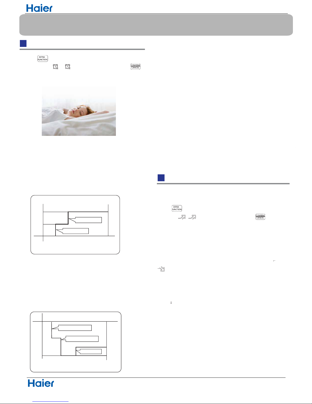
Sleep Operation
5.Fan Speed in Sleep Mode
When the unit is set to sleep mode, the fan speed
will be set to low speed and it cannot be changed.
Operation Mode
1. In COOL,DRY mode
SLEEP operation starts SLEEP operation stops
SLEEP
operation starts
SLEEP
operation stops
Approx.6hrs
1 hr
1 hr
1 hr
3 hrs
3 hrs
Rises 1OC/ 2 F
Rises 1
O
C/ 2 F
Rises 1OC/ 2 F
Temp.setting
Temp.setting
Unit stop
Unit stop
In COOL, DRY mode
In HEAT mode
Decreases 2OC/ 4 F
Decreases 2
O
C/ 4 F
1 hr
2.
3.
In HEAT mode
In AUTO mode
4. In FAN mode
It has no SLEEP function.
Note
When TIMER function is set, the sleep function can’t be
set up .After the sleep function is set up, if user set up
TIMER function, the sleep function will be cancelled; the
machine will be in the state of timing-on.
Power/Quiet Operation
1 hour after SLEEP mode starts,temp.will become
higher than temp.setting.After another 1 hour,temp.rises
by 1 / 2 F futher. The unit will run for an additional 6
hours then stops Temp. is higher than temp.setting so
that room temperature won’t be too low for your sleep.
1 hour after SLEEP mode starts,temp will become 2
4 F lower than temp.setting.After another 1 hour,temp
decrease by 2
C / 4 F futher.After more another 3 hours,
temp.
rises by 1 C / 2 F futher.The unit will run for an
additional 3 hours then stops.Temp.is lower than temp.
setting so that room temperature won’t be too high for
your sleep.
If the unit is running cooling, the sleep mode will follow
the function as in cool mode, while follow as in heat mode.
O
C
O
O
1
O
C/2 F
O
C /
Press button to enter additional options, cycle
the display to , will flash. And then press
enter for sleep function.
(1)
Power Operation
(2)
Quiet Operation
Note
When you need rapid heating or cooling, you can use this function.
You can use this function when silence is needed for rest or
Running the unit in QUIET mode for a long period may
cause the room temperature to not reach the set
temperature. If this occurs, cancel QUITE mode and set
the fan speed to a higher setting.
reading.Press QUIET button, the remote controller will show
, and then achieve to the quiet function. To cancel this
function, press the QUIET button.
Press button to enter additional options, cycle the
display to , will flash,and then press ,enter to
power function. To cancel this function, please select a
different option.
O
O
O
O
O
O
O
O
O
O
Installation
Domestic air conditioner
28
Page 31

Operation
1.After unit starts, select your desired operation mode.
2.Press TIMER button to change TIMER mode. Every
time the button is pressed, display changes as follows:
Remote controller:
BLANK
TIMER ON TIMER OFF TIMER ON-OFF
Then select your desired TIMER mode (TIMER ON or
TIMER OFF or TIMER ON-OFF). " "or " "will flash.
3.Press / button to set time.
It can be adjusted within 24 hours.
Hints:
After replacing batteries or a power failure happens, time
setting should be reset.
According to the Time setting sequence of TIMER ON or
TIMER OFF, either Start-Stop or Stop-Start can be achieved.
Timer On/Off On-Off Operation
Healthy Airflow Operation
1.Press to start
Setting for comfortable conditions.
2.The setting of healthy airflow function
Note:
1.After setting the healthy airflow function, the position
louver is fixed.
4.In cooling and dry, using the air conditioner for a long
time under the high air humidity, condensate water may
occur at the grille .
3.To cancel of the healthy airflow function
Notice: Do not direct the horizontal louver by hand. This
may cause the louver to run incorrectly and not match the
display. If the louver is not running correctly, stop the unit
for a minute and then restart and adjust remote
controller.
2.In heating, it is better to select the
3.In cooling, it is better to select the
mode.
mode.
TIMER OFF-ON
0.5h
0.5h 0.5h
0.5h
Press the button for each time, setting time in the first
12 hours increased by 0.5 hour every time, after 12
hours,increased by 1 hour every time.
Press the button for each time, setting time in the first
12 hours decreased by 0.5 hour every time, after 12
hours,decreased by 1 hour every time.
After adjusting the time,press button and confirm
the time the ON or OFF button will not flash any more.
4.Confirm timer setting
5.Cancel timer setting
Press the timer button until the time display eliminated.
Press button to enter additional options,Press this
button continuously, the louvers location will cycle between
the following three locations, to choose the swing location
what you want, then button to confirm.
Press button to enter additional options,Press this
button continuously, the louvers location will cycle between
the three locations again, then button to cancel.
Healthy
airflow
upwarder
Healthy
airflow
downwarder
Present
position
Domestic air conditioner
29
Installation
Page 32

Maintenance
Setting of proper room
temperature
Close doors and windows
during operation
If the unit is not to be used
for a long time, turn off the
power supply main switch.
Use the timer effectively
Use the louvers effectively
Do not block the air inlet
or outlet
Proper
temperature
During cooling operation
prevent the penetration
of
direct sunlight with
curtain or blind
OFF
Remote Controller Indoor Unit
1.Open the lnlet Grille
2.Detach the Standard Air Filter
3.Attach Air Purifying Filter
4.Attach the standard air filter
(Necessar
y installation)
5.Close the Inlet Grille
Close the inlet grille securely
Slide the knob slightly up
ward to
release the filter, then withdraw it.
Put air purifying filter into the
right and left filter frames.
NOTE:
The photocatalyst air purifying filter will be solarized in fixed
time. In normal use, it will be solarized every 6 months.
Prop up the inlet grille by using the
grille-support located an the right
ATTENTION:
Please keep the bacteria-killing medium air purifying filter
The bacteria-killing medium air purifying filter will be used
for a long time,no need for replacement. But in the period
of using them ,you should remove the dust frequently by
side of the indoor unit.
using vacuum cleaner or flapping them lightly,otherwise ,
its performance will be affected.
cool and dry. Avoid long term exposure to sunlight when not
in use as its ability to sterilize will be reduced.
For Smart Use of The Air Conditioner
Replacement of Air Purifying Filter
The white side of the photocatalyst air purifying filter
faces outside,and the black side faces the unit The green
side of the bacteria-killing medium air purifying filter faces
outside,and the white side faces the unit.
Do not use water, wipe the remote
with a dry cloth. Do not use glass
cleaner or a chemicals.
Wipe the air conditioner by using a
soft and dry cloth.For serious stains,
use a neutral detergent diluted with
water.Wring the water out of the
cloth before wiping,then wipe off the
detergent completely.
Air Filter Cleaning
Open the inlet grille by pulling it upward.
Remove the filter.
Clean the filter.
Attach the filter.
Close the inlet grille.
Push up the filter's center tab slightly until it is
from the stopper, and remove the filter do
wnw
ard.
Use a vacuum cleaner to remove dust, or wash the filter with
water.After washing, dry the filter completely before putting it back in
Attach the filter correctly so that the "FRONT" indication
facing to the front.Make sure that the filter is
fixed behind the stopper.If the right
attached correctly, that
Do not use the following for cleaning
Gasoline,benzine, thinner or cleanser
ay
damage the coating of the unit.
Hot water over 40
O
C(104OF) may
discoloring or deformation.
Once every
two weeks
m
cause
released
is
completely
and left filters are not
may cause defects.
Detach old Air Purifying Filter
the unit.
Installation
Domestic air conditioner
30
Page 33

the power supply cord.
2.
Do not install in the place where there is any
possibility of inflammable gas leakage around
the unit.
3.Do not get the unit exposed
to vapor or oil steam.
Cautions
Connect the earth
cable.
earthing
WARNING
If something abnormal occurs immediately
stop the operation button and contact service
technician.
OFF
Connect to a single
circuit outlet.
ENFORCEMENT
Connect power supply cord
to the outlet completely
Use the proper voltage
Do not use power supply
cord in a bundle.
Take care not to damage
the power supply cord.
1.Do not use extension cords or plug adapters.
STRICT
ENFORCEMENT
STRICT
STRICT
ENFORCEMENT
PROHIBITION
PROHIBITION
PROHIBITION
PROHIBITION
Do not start or stop the
operation by disconnecting
Do not channel the air flow directly
at people.
Do not attempt to repair the
unit. Call for an authorized
service technician.
Do not place or store any objects on the
indoor unit.
CAUTION
Take fresh air occasionally especially
when gas appliance is running at the
same time.
PROHIBITION
STRICT
ENFORCEMENT
Do not operate the switch with
wet hand.
PROHIBITION
PROHIBITION
PROHIBITION
PROHIBITION
PROHIBITION
Do not install the unit near a fireplace
or other heating apparatus.
Install the outdoor unit securely on a
base.
Do not pour water onto the unit
for cleaning
PROHIBITION
Do not place animals or plants in
the direct path of the air flow
Do not place any objects on or
climb on the outdoor unit.
Do not place flower vase or water
containers on the top of the unit.
Do not insert objects into the air inlet or outlet of
the outdoor unit..
PROHIBITION
PROHIBITION
PROHIBITION
STRICT
ENFORCEMENT
Check proper
installation of the
drainage securely
WARNING
Do not install the air conditioner by yourself improper installation may cause fire, water
This system must be installed by a qualified HVAC professional.
leakage, personal injury or death.
Domestic air conditioner
31
Installation
Page 34

Trouble shooting
Normal
performance
inspection
Noise is heard
Phenomenon
Cause or check points
The system
immediately.
Odors are present
Mist or steam are
Multiple
check
Poor cooling
When unit is stopped, it won't restart
elapsed to protect the system.
When the electric plug is pulled out
and reinserted, the protection circuit
During unit operation or at stop,
a swishing or gurgling noise may
(This noise is generated by
refrigerant flowing in the system.)
Should there be a big noise from
filter may be too dirty.
The system circulates any remaining
odors.
During COOL or DRY operation,
This is due to the sudden cooling
Is the power chord correctly position in
the outlet?
Is there a power failure?
Has a fuse or circuit breaker been
tripped?
Is the air filter dirty?
Are there any obstacles in front of
Is temperature set correctly?
Are there some doors or
Is there any direct sunlight
through the window during the
Are there too many heat sources or too
many people in the room during cooling?
In dry mode,
fan
speed can’t be
changed.
In DRY mode, when room temperature
setting+35.6
o
F,unit will run
regardless of FAN setting.
cooling operation?(Use curtain)
windows left open?
inlet and outlet?
Normally it should be cleaned
every 14 days.
intermittently at LOW speed
becomes lower than temp.
indoor unit may blow out mist.
of indoor air.
air flow in unit operation, air
be heard.At first 2-3 minutes after
unit start, this noise is more noticeable.
will work for 3 minutes to protect the
air conditioner.
immediately until 3 minutes have
Cautions
Do not obstruct or cover the ventilation
conditoner.Do not put fingers
inlet/outlet and
swing louver.
Do not allow children to play with the air
conditioner
case should children be
allowed to sit on the outdoor unit.
1.Applicable ambient temperature range:
Specifications
The machine is adaptive in following
situation
The power plug and connecting cable
acquired the local
2. If the power supply cord is damaged, it
must be replaced
manufacturer
3. All electrical wiring must be done to applicable local and state codes.
4. An electrical outlet must be within distance of the indoor unit.
5. When replacing batteries, the batteries removed should be disposed
of properly.
6. Assure that the proper outlet is being used with the power cord.
8. In order to protect the units,please turn off the unit first, wait 30
seconds and turn off the power.
7.
grille of the air
or any objects into the
.In no
or its service agent.
must have
Before calling for service, check the following
first.
blown out.
does not restart
by the
attestation.
The refrigerating circuit is a sealed system.
Cooling
Indoor
Maximum:D.B/W.B
Maximum:D.B/W.B
D.B
Maximum:D.B
D.B
Minimum:D.B/W.B
Maximum:D.B/W.B
Minimum:D.B/W.B
Outdoor
Indoor
Outdoor
Heating
89.6 /73.4
75 /65
115 /75
80.6
67 /57
Outdoor
Maximum:D.B/W.B
Minimum:D.B
5
(INVERTER)
32
Minimum:
Minimum:
67 /57
75 /65
19.4
Installation
Domestic air conditioner
32
Page 35

Drawing for the installation of indoor and outdoor units
Necessary Tools for Installation
●
Torque wrench
●
(0.67 in,0.87in ,1.02in)
Nipper
●
Reamer●
Hacksaw●
Pipe cutter●
Gas leakage detector or●
soap-and-water solution
Hole core drill●
Flaring tool●
Spanner(0.67,0.75 and 1.02in )●
Knife●
Measuring tape●
●
Selection of Installation Place
Power Source
Preparation
The above picture is for reference only. Your product may look different.
Read this manual before installation
Explain the operation of the unit to the user according to this manual
Installation Manual of Room Air Conditioner
F
A
C
E
D
Optional parts for piping
Non-adhesive tape
Adhesive tape
Saddle (L.S) with screws
Connecting electric cable
for indoor and outdoor
Drain hose
Insulating material
Piping hole cover
Floor fixing dimensions of the outdoor unit
Fixing of outdoor unit
Fix the unit to concrete or block●
with bolts
(10mm) securely.
When fitting the unit to wall
●
surface, roof or
rooftop, fix the unit securely in consideration
of
earthquake and strong wind.
If vibration may affect the
●
house, fix the unit
by attaching a
vibration-proof mat.
The marks from to
in the figure are the
name of the parts.
The distance between
the indoor unit and the
floor should be more
than 2m or 6 feet.
The models adopt HFC free refrigerant R410A
more than
10cm
more than 5cm
more than
more than10cm
more than 15cm
more than 60cm
A
G
●
●
A
F
C
E
D
G
B
Arrangement of piping
directions
Rear left
Left
Rear
right
Right
Below
G
Attention must be paid to
the pitch of drain hose
X Y X
Z
Dimensions(inches)
Model
x y z
Hammer
●
●
●
●
Place where the distance of more than lm from televisions, radios, wireless apparatuses
and fluorescent lamps 3 feet or approximately.
●
In the case of fixing the remote controller on a wall, place where the indoor unit can
receive signals when the fluorescent
●
lamps in the room are in use.
●
●
●
A distance marked
●
is available as illustrated in the below figure.
Indoor Unit - Select a location that is
Outdoor Unit - Select a location that is
Robust not causing vibration, where the unit can be supported s ufficiently.
Not affected by heat or steam generated in the vicinity, and where the inlet and outlet of
the unit are not disturbed.
Possible to drain easily, and where piping can be connected with the outdoor unit.
Where conditioned air can be spread in a room evenly.
Less affected by rain or direct sunlight and is sufficiently ventilated.
Strong enough to bear the unit, where vibration and noise are not increased.
Not causing a nuisance to neighbors due to discharged air or noise.
(Unit: inch)
5 1/2
19 2/3
10 1/16
(2 inches)
(4 inches)
(4 inches)
(4 inches)
more than10cm
(4 inches)
(5 7/8 inches)
(24 inches)
All wiring to the unit must be in accordance with the National Electric code
and local ordinances.
HSU12VHGL-W
System configuration
Domestic air conditioner
33
10cm
Page 36

Indoor unit
Make a hole of B mm / inches
in diameter, slightly descending
to outside the wall.
●
Install piping hole cover and seal it off with putty after installation
●
When the mounting plate is first fixed
1. Carry out, based on the wall studs or lintels, a
to be fixed against the wall, then temporarily fasten the plate with one nail.
2. Ensure
the proper level of the plate, by
hanging a thread with a
weight from the central top of the plate, then fasten the plate.
3. Find the wall hole location A using a measuring tape
1
Fitting of the Mounting Plate and
Positioning of the wall Hole
Lid for right
piping
Lid for under piping pipe
Fix with adhesive tape
Lid for left piping
Indoor/outdoor electric cable and drain hose must be bound with refrigerant
●
piping with adhesive.
[ Other direction piping ]
Cut away, with a nipper, the lid for piping according to the piping direction and
●
then bend the pipe according to theposition of wall hole. When bending, be
careful not to crush
pipes.
Make sure that the wires connecting the indoor and outdoor units are not covered
by the refrigeration piping insulation and are long enough to connect to the terminal
block on the indoor unit.
●
proper leveling for the plate
2
Making a Hole on the Wall and Fitting the Piping Hole Cover
Drawing of pipe
3
Installation of the Indoor Unit
[ Rear piping ]
Draw pipes and the drain hose, then fasten them with the adhesive tape
●
[ Left·Left-rear piping ]
In case of left side piping, cut away, with a nipper, the lid for left piping.
●
In case of left-rear piping, bend the pipes according to the piping direction to
●
the mark of hole for left-rear piping which is marked on insulation materials.
1. Insert the drain hose into the carity of heat insulation materials of indoor unit.
2. Insert the indoor/outdoor electric cable from backside of indoor
unit, and pull it
out o
n the front side, then connect them.
3. Coat the flaring seal face with refrigerant oil and connect pipes.
Cover the tubing connection with insulation materials closely, and with adhesive
tape.
Fixing the indoor unit body
Hang the unit body onto the upper notches of the
●
mounting plate. Move the body from side to side to verify
its
secure fixing.
In order to fix the body onto the mounting plate,hold up
●
the body from the underside and then put it down
perpendicularly.
mounting plate
When you unload the indoor unit,please use
lift the bottom of the body outward
slightly and lift the unit until
it leaves the mounting plate.
agraffe
mounting plate
Unloading of indoor unit body
●
your hand to raise the body , then
Remote controller (1)
AAA dry battery (2)
Mounting plate (1)
Drain hose (1)
Ø4X25 Screw
(4)
Plastic cap (4)
Drain-elbow (1)
Cushion (4)
Pipe supporting plate (1)
Accessory parts
NOTE:The thickness of the pipe must be 0.8mm(1/16”) at least.
Selection of pipe
Insulation
material
Drain hose
Piping
Pipe supporting
plate
Indoor/outdoor electric c able
Indoor side
Outdoor side
ØBmm
Wall hole
Thickness of wall
(Section of wall hole)
Piping hole pipe
G
Model Liquid pipe (Ø)
Gas pipe (Ø)
6.35mm (1/4")
12.7mm (1/2")
09k/12k : B= 60mm(2 3/8 inches)
18k/24k : B=70mm(2 3/4 inches)
Pitch downward for drainage
Pay attention to the following points before installation of machine:
1. Take out cushion blocks on
the left and right angle beads
as shown in the following
Figure.
2. Remove 2 gaskets under the
cross-flow fan.
3. Clean the burr on the surface of fracture to avoid the power
wire from being scratched after removing the virtual opening
of the outgoing line slot on the case by hands in indoor
power-on process.
HSU18VHGL-W
A=145mm
B= 60mm
30mm
A=145mm
B= 60mm
30mm
A=125mm
B= 70mm
30mm
Domestic air conditioner
34
Installation
Page 37

Outdoor unit
Indoor unit
A
B
Outdoor unit
Indoor unit
A
B
A
B
Outdoor unit
Indoor unit
Oil trap
Outdoor unit
Install according to the instructions on the 1st page of this manual
When bending the interconnect tubing, ensure the radius is at least 1 1/4" to 1 3/4",
30mm to 40mm to ensure against crushing the tubing.
●
Connecting the pipe of gas side first makes working easier.
●
Ensure the interconnecting tubing is approved for R410A.●
Installation of Outdoor Unit
Half union
Flare nut
Torque wrench
CAUTION
Spanner
Forced fastening without careful centering may
damage the threads and cause a leakage of gas.
1
Connection of pipes
2
1. If the supply cord is damaged, it must be replaced by the manufacturer or its
service agent or a similar qualified person. The type of connecting wire is
H05RN-F
or H07RN-F.
2. If the fuse on PC board is broken please change it with the
type of
3. The wiring method should be in line with the local wiring standard.
4. Use an HVACR circuit breaker or time delay fuse.
T.3.15A/250VAC (Indoor), T.25A/250VAC (Outdoor).
4
Connecting the indoor/outdoor Electric Cable
Removing the wiring cover
Remove terminal cover at right bottom corner of indoor unit, then take off●
wiring cover by removing its screws.
1. Insert the cable from the outside into the unit through the same
hole that has the interconnecting tubing.
2. Pull out the cable on the front side, and connect the cable
making a loop.
Note
When connecting the cable, confirm the terminal number of indoor and
outdoor units carefully. If wiring is not correct, the unit will not operate
When connecting the cable after installing the indoor unit
When connecting the cable before installing the indoor unit
{
Indoor unit
Outdoor unit
1
2
N
2
)
(
3
(C)
L
1
)
(
•
Max.Elevation: Amax
= 32.8ft / 10m (09k / 12k)
= 50ft / 15m (18k / 24k)
•
In case the elevation A is more
than 16.4ft / 5m, oil trap shoud be
installed every 5~7m(16.4ft-23ft)
•
Max. Length: Bmax
= 50ft / 15m (09k / 12k)
= 83.3ft / 25m (18k / 24k)
●
●
●
Insert the cord from the back side of the unit, then pull it out on the front side.
Fasten the unit wire harness to the conduit holder using the lock nut.
Position the conduit holder to its original state using screw.
Power cable:
3wire with ground 14AWG
Power
Wiring
4wire 14AWG
Control Wiring
Pipe Diameter(ǿ) Fastening torque
Liquid side6.35mm(1/4") 18N.m/13.3Ft.lbs
Liquid/Gas side9.52mm(3/8") 42 N.m/30.1Ft.lbs
Gas side 12.7mm(1/2") 55N.m/40.6Ft.lbs
Gas side 15.88mm(5/8") 60 N.m/44.3Ft.lbs
properly and could cause a defect.
Ensure that no dirt or debris enters the tubing. The standard tubing length is 25 ft/7.5M.
If a different length is required, adjust the refrigerant amount by 1/2 oz/ft, 50 g/M for the
9k, 12k and 18k models. For the 24k model, adjust by 1/2 oz/ft, 50 g/M.Before opening
the service valves, evacuate the interconnecting tubing and indoor unit. Follow the
instruction in section 5 on page 4.
Pipe cutting is carried out with a pipe cutter and burs must
●
be removed.
After inserting the flare nut, flaring work is carried out.
●
Cutting and Flaring Work of Piping
Flare tool for R410A Conventional flare tool
Clutch-type clutch-type(Rigid-type) Wing-nut type (Imperial-type)
A
0~0.5mm
1.0~1.5mm
1.5~2.0mm
0~1/51 inch
3/76 ~1/17 inch
1/17 ~1/8 inch
Flare tooling die
1.Cut pipe
2.Remove burs
3.Insert the flare nut
4.Flare pipe
Lean
Damage of flare Partial Too outside
Correct Incorrect
Crack
HSU18VHGL-W
(4G0.75mm )
Installation
Domestic air conditioner
35
Page 38

Detach the service port’s cap of
1.
3-way valve, and the valve cap for 2-way valve
and 3-way valve. Connect the service port to the low side of the gauge manifold
Open the handle on the low side of the gauge manifold and operate vacuum pump.
2.
Vacuum the tubing for at least 15 minutes. The vacuum level on the low side gauge
should be 29.9 in of Hg, 76 cm of Hg, 0.1 MPa. when vacuuming is complete, close
the valve on the manifold and turn off the vacuum pump. The vacuum level should
hold for 1-2 minutes. If the vacuum level does not hold, check the flared connections
and repeat this step.
3.
Purging Method:To use vacuum pump
5
Open
Open the 2-way valve 1/4 turn. After 5-6 seconds, close the valve and inspect for
leaks with a leak detector or soap solution.
4.
No gas leakage? Go to step 6.
5.
Detach the charge hose6.
from the service port,
open 2-way valve and 3-way
Gauge manifold
Gaugemanifold(for
R410A)
2-way valve Liquid Side
3-way valve Gas Side
Vacuum pump
Tube(for R410A)
Close
2-way valve
3-way valve
Open 90
O
2-way valve
3-way valve
2-way valve
3-way valve
2-way valve
3-way valve
Valve cap
Valve cap
Service port cap
After attaching the caps, check for leakage around the caps.
7.
8.
Step 1.
Step 2.
Step 3.
Step 7.
Step 6.
Step 4.
The power source must be exclusively used for air
●
conditioner.
In the case of installing an air conditioner in a moist place,
●
please install an ea-
For installation in other places, use an HVACR circuit breaker of time delay fuse.
●
If the refrigerant of the air conditioner leaks, it is necessary to discharge all the
●
according to the amount marked on the name plate.
Please do not let other cooling medium, except specified one (R410A), or air
●
enter into the cooling circulation system. This could cause high pressure and
1
Power Source Installation
CAUTION
rth leakage breaker.(GFCI)
2
On Drainage
It becomes
high midway.
The gap with the
ground is too small.
There is the bad
smell from a ditch
It waves.
The end is immersed in water.
Please install the drain hose and ensure downward flow.
Please don’t do the drainage as shown below.
●
●
Please pour water in the drain pan of the indoor unit, and
●
is proper.
In case that the attached drain hose is in a room, please
●
apply insulation
to
Less than
5cm
confirm that drainage
to the hose to prevent condensation.
Check Items for Test Run
Please kindly explain to our customers how to operate
through the instruction manual.
Check for Installation and Test Run
■
■
1
1+2=
kg
R410A
2
kg
2=
1=
B
C
D
F E
kg
A
This product contains fluorinated greenhouse gases covered by
the Kyoto Protocol. Do not vent into the atmosphere.
Refrigerant type:R410A
GWP* value:1975
GWP=global warming potential
Please fill in with indelible ink,
• 1 the factory refrigerant charge of the product
• 2 the additional refrigerant amount charged in the field and
• 1+2 the total refrigerant charge
on the refrigerant charge label supplied with the product.
The filled out label must be adhered in the proximity of the product
charging port (e.g. onto the inside of the stop value cover).
A contains fluorinated greenhouse gases covered by the Kyoto
Protocol
B factory refrigerant charge of the product: see unit name plate
C additional refrigerant amount charged in the field
D total refrigerant charge
E outdoor unit
F refrigerant cylinder and manifold for charging
Contains fluorinated greenhouse gases
covered by the Kyoto Protocol
Refrigerant charge label■
Put check mark
in boxes
To prevent the gas
leakage,
continues, remove the refrigerant used for the leakage check and flare
tubes again. Repeat vacuum and leak and if no leakage, proceed to step 6.
replace the service port and valve caps.
Gas leak from interconnecting tubing?
Installation is on the interconnecting tubing?
Are the connecting wirings of indoor and outdoor firmly
Is the connecting wiring of indoor and outdoor firmly fixed?
Is drainage securely carried out?
Is the ground wire securely connected?
Is the indoor unit securely fixed?
Is power source voltage the local codes?
Is there any noise?
Are the lights near the unit working normally?
Are cooling and heating (when in heat pump) performing
normally?
Is the operation of room temperature control normal?
inserted to the terminal block?
Loosen the screws on
●
terminal block and
insert the wires fully into terminal
block, then tighten the screws.
If wiring is not correct, the unit will not operate properly and it could cause a
●
Fix the cable with a clamp.●
Connection
3
If the drain-elbow is used,●
please attach as shown in figure.
(Note:
Only for heat pump unit.)
Attaching Drain-Elbow
4
defect in the unit.
and connect the vacuum pump to the center port of the manifold.
In case of a leak, try tightening the flare connections to fix the leak. If the
leak stops, go to step 6. If the leak continues, check the flare connections
and repair as needed, then go back to step 3. then proceed step 6. If leak
valve completely.
refrigerant. Repair the leak, vacuum the unit then charge the liquid refrigerant
into air conditioner
could cause a leak and lead to personal injuries.
Installation
Domestic air conditioner
36
Page 39

Seivice diagnosis
Domestic air conditioner
9.Dimensional drawings
10.Center of gravity
37
3.27
3.27
0.77
1.06
0.26
0.26
1.16
1.12
1.06
0.46
0.77
0.37
Page 40

Seivice diagnosis
Domestic air conditioner
11 Service Diagnosis
11.1 Caution for Diagnosis
The operation lamp flashes when any of the following errors is detected.
1. When a protection device of the indoor or outdoor unit is activated or when the thermistor malfunctions,
disabling equipment operation.
2. When a signal transmission error occurs between the indoor and outdoor units. In either case, conduct the
diagnostic procedure described in the following pages.
11.3 Problem Sympt oms and Measures
erusaeMfosliateDmetIkcehCmotpmyS
None of the units
operates
Check the power supply. Check to make sure that the rated voltage is supplied.
Check the indoor PCB. Check to make sure that the indoor PCB is broken.
Operation
sometimes stops
Check the power supply.
A power failure of 2 to 10 cycles can stop air conditioner
operation.
Equipment
operates but
does not cool, or
does not heat
(only for heat
pump)
Check for faulty operation
of the electronic
expansion valve.
Set the units to cooling operation, and compare the
temperatures of the liquid side connection pipes of the
connection section among rooms to check the opening and
closing operation of the electronic expansion valves of the
individual units.
Diagnosis by service port
pressure and operating
current.
Check for insufficient gas.
Large operating
noise and
vibrations
Check the installation
condition.
Check to make sure that the required spaces for
installation (specified in the Technical Guide, etc.) are
provided.
38
11.2 Parameter of primary electronic appliance
N O N a m e Pa ra m eter Picture
1 F a n m otor
R a te d vo ltag e :
DC310V
R a te d cu rr e nt:0 .17A
R a te d freq u en c y:
R e sis ta n ce :5 4 8Ω
-
Page 41

Seivice diagnosis
Domestic air conditioner
11.4 Error Codes and Description indoor display
Code indication
fault description
Reference
Page
Indoor
displaying
panel code
indication
Outdoor
(LED1 flash
times)
Indoor and
Outdoor
E7 15
Communication fault between indoor and
outdoor units
Page .
Indoor Malfunction
E1 -- Room temperature sensor failure Page .
E2 -- Heat-exchange sensor failure Page .
.egaProrreMORPEEroodnI--4E
E14 -- Indoor fan motor malfunction Page .
Outdoor
Malfunction
F12 1 Outdoor EEPROM error Page .
F1
2
.egaPMPIfonoitcetorpehT
F22
3
Overcurrent protection of AC electricity
for the outdoor model
Page .
F3 4
Communication fault between the IPM and
outdoor PCB
Page.
F19 6 Power voltage is too high or low Page .
F4 8
Overheat protection for Discharge
temperature
Page .
F8 9 Outdoor DC fan motor fault
F21 10 Defrost temperature sensor failure Page .
F7 11 Suction temperature sensor failure Page .
F6 12 Ambient temperature sensor failure Page .
F25 13 Discharge temperature sensor failure Page .
F11 18 deviate from the normal for the compressor Page .
F28 19 Loop of the station detect error Page .
F2 24 Overcurrent of the compressor Page .
F23 25
Overcurrent protection for single-phase of the
compressor
Page .
E9
21 High work-intense protection
39
50
40
40
41
42
41
45
46
47
48
49
44
Page .
40
40
40
40
52
52
46
46
Page .53
Page 42

Seivice diagnosis
Domestic air conditioner
11.4.1 Ther mistor or Related Abnormality
The temperatures detected by the thermistors are used to determine thermistor errors
when the thermistor input is more than 4.92V or less than 0.08V during compressor
operation.
Note: The values vary slightly in some models
■ Faulty connector connection
■ Faulty thermistor
■ Faulty PCB
* Caution Be sure to turn off power switch before connect or disconnect connector, or else
parts damage may be occurred.
Thermistor resistance check method:
Remove the connector of the thermistor on the PCB, and measure the resistance of thermistor using tester. The
relationship between normal temperature and resistance is shown in the value of indoor thermistor.
Method of
malfunction tection
Malfunction
detection conditions
*Thermistor
resistance check
Yes
Troubleshooting
E1: Room temperature sensor failure
E2: Heat-exchange sensor failure
LED1 flash 10 times:Defrost temperature sensor failure
LED1 flash 11 times:Suction temperature sensor failure
LED1 flash 12 times:Ambient temperature sensor failure
LED1 flash 13 times:Discharge temperature sensor failure
Indoor display
Outdoor display
40
Thermistor resistance check
Is it normal?
YES
NO
YES
Is it normal?
NO
Check the connector onnection
Replace the thermistor
Replace the indoor unit PCB
Correct the connection
Page 43

Seivice diagnosis
Domestic air conditioner
Indoor Display E4: indoor EEPROM error
outdoor display F12: Outdoor EEPROM error; Outdoor LED1 flash 1 times
Method of
malfunction
detection
Malfunction
detection
conditions
Supposed
causes
Troubleshooting
The Data detected by the EEPROM are used to determine MCU
when the data of EEPROM is error or the EEPROM is damaged
■Faulty EEPROM data
■Faulty EEPROM
■Faulty PCB
* Caution Be sure to turn off power switch before connect or disconnect connector,
or parts damage may be occurred.
Replace the indoor or outdoor mainboard
41
11.4.2 EEPROM abnormal
Page 44

Seivice diagnosis
Domestic air conditioner
11.4.3
Indoor fan motor malfunction
42
Indoor Display
E14
Method of
The rotation speed detected by the Hall IC during fan motor operation is used to determine
Malfunction
abnormal fan motor operation
Detection
Malfunction
when the detected rotation feedback singal don’t receiced in 2 minutes
Decision
Conditions
Supposed
■ Operation halt due to breaking of wire inside the fan motor .
Causes
■ Fan motor overheat protection
■ Operation halt due to breaking of the fan motor lead wires
■ Detection error due to faulty indoor unit PCB
Troubleshooting
* Caution
Be sure to turn off power switch before connect or disconnect connector, or
else parts damage may be occurred.
How to check Fan Motor (DC)
1. Check connector connection.
2. Check motor power supply voltage output (pins 1-4).
3. Check motor control voltage (pins 4-5).
4. Check rotation command voltage output (pins 4-6).
5. Check rotation pulse input (pins 4-7).
Notes: the a/c is electrifying, don’t pull out or insert the terminals of the
motor, else the motor would be damaged.
Page 45

Seivice diagnosis
Domestic air conditioner
43
YES
NO
YES
Is rotation number
command pulse
generated?
Is rotation number
command voltage
DC1~6V generated?
YES
YES
NO
NO
YES
Replace indoor unit PCB
Replace fan motor
Replace indoor
unit PCB
Replace indoor fan motor
PCB
NO
Replace indoor unit PCB
Is motor control power
voltage DC15V
g
enerated?
NO
Does fan rotate
smoothly?
NO
Turn power ON and operate fan
Does it rotate?
YES
Turn off power supply and disconnect fan
motor connector, then turn power ON
Check output of fan motor connector
Is motor powe r
voltage DC310V
g e n e r a t e d ?
Replace fan motor
Stop fan motor
Turn off power supply and rotate
fan by hand
Page 46

Seivice diagnosis
Domestic air conditioner
44
11.4.4 Outdoor DC fan motor fault
Check whether Terminal on the outdoor
mainboard is well inserted.
Is it normal?
YES
NO
Reinsert the terminals
Electrify the machine again and turn
it on in the Cool state with the remote
controller. check whether motor can
run?
YES
Measure the voltage between 3 and 6 of
the terminal about 0-5v.
Is it normal?
NO
the motor of the outdoor unit is damaged
and needs replacing.
Measure the voltage between 1 and 3 of the terminal of
fan motor on the mainboard about DC310V,Measure
the voltage between 3 and 4 of the terminal about
DC15V. Measure the voltage between 5 and 3 of the
terminal about 1-6v.
NO
Is it normal?
The mainboard of the outdoor unit is
damaged and needs replacing.
NO
YES
YES
Method of
m
alfunction detection
Malfunction detection
conditions
Troubleshooting
DC fan motor is detected by checking the fan running condition and so on
when the data of EEPROM is error or the EEPROM is damaged
■
DC fan motor protection dues to the DC fan motor faulty
■
DC fan motor protection dues to faulty PCB
Supposed causes
* Caution
Be sure to turn off power switch before connect or disconnect connector, or parts damage
ma
y be occurred.
LED1 flash 9 timesOutdoor diplay
Page 47

Seivice diagnosis
Domestic air conditioner
11.4.5 IPM protection
Electrify the machine again and turn it on
with the remote controller,If malfunctions
are reported before or upon the compresso
r
being started up,
IPM Module is damaged and
needs replacing.
1、The system may have been over or under charged with gas, which can be judged through the pressure of the
measuring system.
2、The shaft of compressor is seized and the compressor needs replacing.
YES
NO
The compressor is started normally, but
malfunctions are reported after it has run for some
time.
Malfunction unsolved
Method of
malfunction
detection
Malfunction
detection
conditions
Troubleshooting
IPM protection is detected by checking the compressor running condition and so on
■The system leads to IPM protection due to over current
■The compressor faulty leads to IPM protection
■circuit component of IPM is broken and led to IPM protection
■IPM protection dues to the compressor faulty
■IPM protection dues to faulty PCB of IPM module
■Com
p
ressor wiringdisconnected
Supposed
causes
* Caution
Be sure to turn off power switch before connect or disconnect connector, or else
parts damage may be occurred.
.
LED1 flash 2 times
Outdoor diplay
45
Page 48

Seivice diagnosis
Domestic air conditioner
11.4.6 Over-current of the compressor
Electrify the machine again and turn it on
with the remote controller, If malfunctions
are reported before or upon the compresso
r
being started up,
IPM Module is damaged and
needs replacing.
Repair the power supply
the system may have been over or under charged
with gas, which can be judged through the
pressure of the measuring system.
YES
NO
YES
NO
The compressor is started normally, but
malfunctions are reported after it has
run for some time. Check the powe
r
supply is too low or too high
NO
Method of
malfunction detection
Malfunction detection
conditions
Troubleshooting
he current of the compressor is too high
when the IPM Module is damaged or the compressor is damaged. power supply
voltage is too low or too high
Supposed causes
LED1 flash 3 or 24 or 25 times
Outdoor diplay
■
Faulty IPM Module
■
Faulty compressor
■
Fault
y p
ower suppl
y
* Caution
Be sure to turn off power switch before connect or disconnect connector, or parts
damage may be occurred..
.
46
Page 49

Seivice diagnosis
Domestic air conditioner
11.4.7 The communication fault between IPM and outdoor PCB
1) Check whether Terminal CN23 and CN24 on the outdoor mainboard
CN10 and CN11 on IPM module
2) Check whether the connected wire between IPM and outdoor
Are they good?
Electrify the machine again and turn it
on, Check whether the voltage between
1 and 2 of Terminal CN23 is about DC5V,
Check whether the voltage between2
and 3 of Terminal CN23 is about DC15V,
Replace the outdoor mainboard with a new one
Replace the outdoor IPM module
with a new one.
YES
NO
NO
YES
Malfunction unsolved
1) Pull out and reinsert the terminals.
2) Replace connected wire
Method of
malfunction detection
Malfunction detection
conditions
Troubleshooting
Communication is detected by checking the IPM module and the outdoor PCB
■The outdoor PCB broken leads to communication fault
■The IPM module broken leads to communication fault
■The outdoor PCB is broken
■The IPM module is broken
■Communication wirin
g
disconnected
Supposed causes
* Caution
Be sure to turn off power switch before connect or disconnect connector, or else
parts damage may be occurred
LED1 flash 4 times
Outdoor diplay
47
Page 50

Seivice diagnosis
Domestic air conditioner
11.4.8 Power Supply Over or under voltage faul t
Electrify the machine again and turn it on with
the remote controller. Check whether the
compressor is started normall
y
Is it ok?
YES
Maybe there is some disturbance
NO
NO
~230 is ok?
YES
YES
This question may be caused by the power. Repair
the power supply.
NO
Change the IPM module
Change the IPM module
Test the outdoor power supply
(+310VDC) with a multimeter.
check whether the power
is >150 V or <390V?
Method of
malfunction detection
Malfunction detection
conditions
Troubleshooting
An abnormal voltage rise or fall is detected by checking the specified voltage detection
An voltage signal is fed from the voltage detection circuit to the microcomputer
■Supply voltage not as specified.
■The IPM module is broken.
■The outdoor PCB is broken.
Supposed causes
* Caution
Be sure to turn off power switch before connect or disconnect connector, or else
parts damage may be occurred.
LED1 flash 6 times The power supply is over voltage
Outdoor diplay
48
Page 51

Seivice diagnosis
Domestic air conditioner
11.4.9 Overheat Protection For Discharge Temperature
Electrify the machine again and turn it on with the remote controller,
then measure the temperature at the exhaust temperature sensor of
the compressor on the outdoor unit
the temperature exceeds
shortly after the
machine starts u
p
?
1) The cryogen may have been leaked during
installation, or there may be leakage in the piping
system.
2) There may be other causes to make the exhaust
temperature too high.
Malfunctions occur after running for some time even
though the measured temperature is below 230°. Pull
out the exhaust sensor and measure its resistance at
standard temperatures according to the
resistance-temperature table
the results deviate
much?
The sensor is damaged. Replace the sensor
with a new one.
The outdoor mainboard is damaged and needs be
re
p
laced
YES
NO
NO
YES
Method of
malfunction detection
Malfunction detection
conditions
Troubleshooting
The Discharge temperature control is checked with the temperature being detected by
the Discharge pipe thermistor
when the compressor discharge temperature is above 230°
■Electronic expansion valve defective
■Faulty thermistor
■Faulty PCB
Supposed causes
* Caution
Be sure to turn off power switch before connect or disconnect connector, or else
parts damage may be occurred.
LED1 flash 8 times
Outdoor diplay
49
F
F
230°
F
Page 52

Seivice diagnosis
Domestic air conditioner
11.4.10 The communication fault between indoor and outdoor
NO
(A)
YES
NO
YES
NO
YES
Restart the a/c and it
becomes normally.
If starting up normally, but
malfunction occurs again after a
while
Check whether the linking cable
between the indoor and outdoor is well
connected or whether its core wires are
well insulated.
The outdoor mainboard needs
dehumidification.
The outdoor mainboard needs
dedust.
1. Reconnect the linking cable;
2. Replace the linking cable with new
one.
Method of
malfunction detection
Malfunction detection
conditions
Troubleshooting
Communication is detected by checking the indoor PCB and the outdoor PCB
■The outdoor PCB broken leads to communication fault
■The indoor PCB broken leads to communication fault
■
Communication wiring disconnected
■The indoor PCB is broken
■The outdoor PCB is broken
■The module PCB is broken
Supposed causes
* Caution
Be sure to turn off power switch before connect or disconnect connector, or else
parts damage may be occurred.
E7
LED1 flash 15 times
indoor diplay
Outdoor diplay
50
Page 53

Seivice diagnosis
Domestic air conditioner
(A)
NO
YES
YES
Check the indoor mainboard.
NO
If the voltage is of a constant
value of 0V DCto5V DC
YES
Measure the voltage between Jumpers 3 and
4 of IC1 on the indoor mainboard with a
multimeter.
NO
The outdoor mainboard is damaged;
Replace them with a new one.
Measure the AC voltage between positions 1
and 3 on the terminal of outdoor unit with a
multimeter.
If 230VAC is available but 310DC not,
the power module is damaged, replace it
with a new one.
Test the outdoor power supply (230VAC
and +310VDC) with a multimeter.
The outdoor mainboard is damaged; replace
it with a new one.
The indoor mainboard is damaged; replace
it with a new one.
If the value varies between 0 and 80 VAC, the
outdoor mainboard is damaged, replace it
with a new one.
If the value is constant at about 30V, the
indoor mainboard is damaged, replace it with
a new one.
If both 230VAC and 310DC are
available, measure +12V
(from7805) is available.
51
Page 54

Circuit diagrams
Domestic air conditioner
11.4.11 Loss of synchronism detection
Inverter side current detection is abnormal
Within 3 minutes after the machine is
supplied with power and turned on with
the remote controller, check whethe
r
the compressor can start up
1. The wiring of compressor is incorrect
or the connection is poor;
2. The compressor is damaged
At first, the compressor start up ,soon the
compressor stopped with the LED1 on the
outdoor PCB blinks(1Hz)19/18 times
IPM Module is damaged and needs
replacing.
the Malfunctions exist also, the
compressor is damaged replace a
new one
YES
NO
YES
Malfunction unsolved
Maybe there is some disturbance
Method of
malfunction detection
Malfunction detection
conditions
Troubleshooting
The position of the compressor rotor can not detected normally
when the wiring of compressor is wrong or the connection is poor; or the compressor
is damaged
■Faulty The wiring of compressor
■Faulty compressor
■Faulty PCB
Supposed causes
* Caution
Be sure to turn off power switch before connect or disconnect connector, or else
parts damage may be occurred.
LED1 flash 18 times
LED1 flash 19 times
Outdoor diplay
52
Page 55

Circuit diagrams
Domestic air conditioner
11.4.12 High work-intense protection
Electrify the machine again and turn it on with the
remote controller, check whether the wind
temperature is below 149°F
The malfunction is reported
after the machine has run
for some time?
1 、 Check room temperature and
pipe temperature sensor.
2、the temperature monitoring circuit
of the indoor mainboard
The indoor unit blows poorly
due to blocked filters or poor
condition of the fan?
1) Clean the filters
2) Reinstall the fan.
Use some tools to measure the pressure of system,
YES
NO
YES
NO
Method of
malfunction detection
Malfunction detection
conditions
Troubleshooting
High work-intense control is activated in the heating mode if the temperature being
sensed b
y
the heat exchanger thermistor exceeds the limit.
Activated when the temperature being sensed by the heat exchanger rises above
149°F twice in 30 minutes.
■Faulty electronic expansion valve
■Dirty heat exchanger
■Faulty heat-exchange sensor
■Insufficient gas
Supposed causes
* Caution
Be sure to turn off power switch before connect or disconnect connector, or else
parts damage may be occurred.
LED1 flash 21 times
Outdoor diplay
53
Page 56

Circuit diagrams
Domestic air conditioner
12. Circuit diagrams
54
+5V
+5V
SCL
SDA
EEPROM
+5V
RESET
+5V
IR
SRCK
RCK
SER
COM3
COM2
GND
+5V
+12V
A
B
C
D
+12V
BUZZER
+5V
SWITCH
+5V
SER
SRCK
GG
RCK
5V
GND
IR
ZJ/SS
DIGH
DIGL
DISPLAY-0011800161
DISPLAY-0011800184/0033
12V
MODE
DIGH
DIGL
SER
SRCK
RCK
LSTEP_A
LSTEP_B
LSTEP_C
LSTEP_D
BUZZ
CHECK/S_TIME
IR
SWITCH
LSTEP MOTOR
+5V
+5V
ONLINE
RST
MODE
DIG_MODE
+5V
LED1
φ3-RED
+5V
P1
2SA1037AK
1B
1
2B
2
3B
3
4B
4
5B
5
6B
6
7B
7
E8COM
9
7C
10
6C
11
5C
12
4C
13
3C
14
2C
15
1C
16
IC8
ULN2003A
MODE
+5V
HXF
TVS1
HTVSB7.0CA-7V-600W
HXF
RST
RST
XT1
FCR8.0MC5
+5V
+12V
FLZ
+12V
+12V
UP-DOWNSTEPMOTOR
1B
1
2B
2
3B
3
4B
4
5B
5
6B
6
7B
7
E
8
COM
9
7C
10
6C
11
5C
12
4C
13
3C
14
2C
15
1C
16
IC12
ULN2003A
USTEP_A
A
B
C
D
12V
A
B
C
D
12V
USTEP _B
USTEP _C
USTEP _D
DSTEP_A
DSTEP_B
DSTEP_C
DSTEP_D
+5V
RX
TX
GND
+5V
NETCOM
+5V
PG-FEEDBACK
+15V
VS
+15V
PG-OUT
IC7
TLP421
IC3 TLP421
+5V
+5V
FK
ROOM-CARD
N3
SS8050LT1
+12V
+5V
REMOTE_TX
REMOTE_RX
FAR
N1
SS8050LT1
N2
SS8050LT1
COMM_RX
COMM_TX
D15
RLS4148
D16
RLS4148
+5V
A/B
+5V
A/B
+5V
25/35
BM
+5V
PIPE
ROOM
ROOM
PIPE
+12V
A
B
C
D
12V
RSTEP MOTOR
1B
1
2B
2
3B
3
4B
4
5B
5
6B
6
7B
7
E8COM
9
7C
10
6C
11
5C
12
4C
13
3C
14
2C
15
1C
16
IC11
ULN2003A
+12V
HXF HXF1
FLZ1
FLZ1
1 2
J45
JX1
IR
1 2
J46
JX2
+5V
1
2
3
4
CN34
5267-04A
VREF
61
KI0/AN8/P10
49
AN7/P0050AN6/P01
51
AN5/P0252AN4/P0353AN3/P04
54
P6255P61
56
CLK1/AN2/P05
57
DA0/AN1/P06
58
VSS/AVS S
59
DA1/AN0/P07
60
VCC/AVCC
62
SSO/P 37
63
SSCK/SCL/P35
64
P33/SSI
1
P34/SDA/SCS
2
MODE
3
P43/XCIN
4
P44/XCOUT
5
RESET
6
P47/XOUT
7
VSS/AVSS
8
P46/XIN
9
VCC/AVCC
10
P54/TCIOD
11
P53/TCIOC
12
P52/TCIOB
13
P51/TCIOA/TCTRG
14
P50/TCCLK
15
P27/TDIOD1
16
(INT2)/P32
45
P15/RXD0/(TRIO)/(IN T1)26P14/TXD0
27
P8628P85/TFO1229P84/TFO11
30
P83/TFO10/TFI31P82/TFO02
32
TFO01/P81
33
TFO00/P80
34
TEO/P60
35
INT0/P45
36
TXD1/INT2/P66
37
RXD1/INT3/P67
38
(CLK1)/CLK2/P65
39
RXD2/P64
40
TXD2/P63
41
TBO/P31
42
TAO/P30
43
KI3/AN11/P13
46
KI2/AN10/P12
47
P26/TDIOC117P25/TDIOB118P24/TDIOA119P23/TDIOD0
20
P17/TAIO/INT1
24
P16/CLK0
25
KI1/AN9/P11
48
P20/TDIOA0/TDCLK
23
P21/TDIOB0
22
(INT1)/P36
44
P22/TDIOC0
21
IC2
R5F212A7SNFA
R3
2K
R11
2K
R10
10K
R23
10K
R63
10K
R54
10K
R85
10K
R94
10K
R29
10K
R30
10K
R33
560Ω
R102
10K
R103
20K
R37 10K
R8
10K
R96 10K
R7 2K
R69 2K
R104 2K
R42 10K
R109 10K
R86 1K
R49 1K
R70 1K
R87 1K
R45 1K
R44 1K
R41 1K
R46 1K
R24 1K
R25 1K
R27
4.7K±1%
R28
4.7K±1%
R6
100Ω
R16
100Ω
R53
100Ω
R18
100Ω
R17
100Ω
R21
100Ω
R31 1K
R93 10K
R62
10K
R40 10K
R34 1K
R73
10K
R106
10K
R38
10K
R43
27Ω
R35
10K
R66
10K
R56
4.7K
R92
2K
R99
2K
R100
2K
R95
10K
R101
10K
R1 10K
R4
1K
R97
100Ω
R98
100Ω
R88
10K
R61
390Ω
R64
10K
R68
10K
R57
10K
R59
10K
R58
2.7K
R36 10K
R39
1K
R84
1K
R48
1K
R52
1K
R60
1K
R65
1K
R67
1K
R75
1K
R51
10K
R55
10K
R110
10K
R8910K
R2
10K
R5 1K
R81 1K
R72
1K
R76
1K
R79
1K
R105
1K
R47
1K
R9
1M
R82
220Ω
R50
2K
R71 10K
C1
100nF
C2
100nF
C3
10nF
C29
10nF
C5
100nF
C24
10nF
C14
1nF
C17
100nF
C10
100nF
C16
100nF
C15 100nF
C6
100nF
C11
100nF
C18
100nF
C20
100nF
C28
100nF
C33
100nF
C19
1nF
C12
100nF
C27
100nF
C21
10nF
C37
1nF
E1
100uF-16V
E3
4.7uF-50V
E5
4.7uF-50V
E2
100uF-16V
E14
4.7uF-50V-105
℃
E15
47uF-50V-105
℃
BUZZ1
PKM13EPY-4002
1
2
3
4
5
6
7
8
9
10
CN5
B10B-PH-K-S
1
2
3
4
CN6
B4B-XH-A
1
2
3
4
5
6
7
8
CN7
B8B-PH-K-S
1
2
3
4
5
6
7
8
9
10
CN7'
B10B-PH-K-S
1
2
3
4
5
6
7
CN9
B5P7-XH-A
1
2
3
4
5
CN10
B5B-XH-A
1
2
3
4
5
CN11
B5B-PH-K
1
2
CN14
B2B-XH-A-R
1
2
3
CN36
B3B-XH-A
1
2
CN51
B2B-XH-A
A0
1
A1
2
A2
3
GND4SDA
5
SCL
6
WP
7
VCC
8
IC1
24C04
1
2
JP1
TJC8-02(
立式
)
1
2
3
4
JP3
TJC8-04
1
2
3
4
JP4
TJC8
-04
(立式)
SW1
TSVC-1
1
2
3
4 5
6
7
8
SW2
NDI-04H
E11
100uF-25V
R108
1K
1
2
3
4
5
CN5-1
B5B-PH-K-S
1
2
3
4
5
CN5-2
B
5B-PH-K-S-
红色-立式
220V_L
N
COMM
IN-OUTCOM
220V_L
L1
LB2271(32mH-0.35A)
BLACK
L
~220VAC
N
WHITE
+5V
COMM_RX
COMM_TX
COMM_TX
COMM_RX
220-L
220-N
N5
SS8050LT1
D11
1N4007
D12
1N4007
ZD4
1N4746A(18V-1W)
IC4
TLP851/PC851
IC6
TLP421
RED
WHITE
FLZ
+12V
220V_L
N
+12V
HXF
D14
RLS4148
D4
RLS4148
FLZ
HXF1
+15V
+310V
R206
270Ω-2W
R004
2.2K
R205
560Ω-0805
R203
100Ω-1206
R202
100Ω-1206
+12V
+15V
IC10
TLP421
R78
47K-2W
D206
FR106(1A-800V-500ns)
D6
1N5399
D8
1N5399
D7
1N5399
D9
1N5399
D20
FR
1
06
(
1A
-
8
0
0
V-
5
00
n
s)
D19
US1M( 1A-1000
V-75ns
)
D008
ER302(3A-200V-35ns)
ZD001
1
N
47
4
6A
(1
8
V
-1W
)
ZD202
1N4742A(12V-1W)
ZD003
1N4742A(12V-1W)
+5V
H-25*15HS1
R019
47Ω-1/2W
NTC1
SCK084R72
INPUT
1
G
N
D
2
OUTPUT
3
IC5
L
7805CV(1.5A-5V
)
15V -100mA
12V -900mA
R209
100Ω-1206
E7
1
00uF
-
45
0
V-105
℃
-
高频
C002
104-630VDC
C23
103-630VDC
C013
2.2nF-250VAC
C009
102-1000V
E204
1000uF-25V-105
℃
E207
47
0u
F
-
16V-
10
5
℃
CY1
2.2nF-250VAC
CY2
2.2nF-250VAC
E8
22u
F
-
5
0
V-105
℃
C004
1
0
p
F-
1
K
V
220-L
220-N
R161
1.5Ω-1/2W
S1B
R
2FB4
VC
C
5
NC
6
D/
S
T
7
D/
S
T
8
GN
D
3
IC9
A6059H
R77
1
0
Ω
-
1
20
6
R90
4.7K
R91
4.7K
R19
10K
R20
1K
R13
330Ω
R22
2K-1/4W
R26
2K-2W
R12
1
00
K
-
1/4W
R14
47K-3W
R15
47K-3W
C7
100nF
C22
100nF
C9
1nF
C8
100nF-50V
C4
100nF
C13
1nF
C010
1nF
CX1
470nF-275VAC
CX2
100nF-275VAC
CY4
2.2nF-250VAC
CY5
2.2nF-250VAC
CY3
2.2nF-250VAC
CY6
4.7nF-250V
E9
4
7
uF
-
50
V
-10
5
℃
E4
100uF-50V-105
℃
1
CN17
D250
1
CN23'
D250
1
CN23
1
CN21
1
CN52
1
CN21'
D250
1
CN27
1
CON1
1
CON2
1CON3
FUSE1
T3.15A/250VAC
3 4
1
2
K2
OJE-SS(H)-112L
(D)
3 4
1
2
K4
OJE-SS
(
H
)
-112L(D
)
N001
KTC8050
4
7
3
6
5
1
T1
BCK-6-FE1901H/ 19ES-X58
RV1
TVR14561*
R80
1.5K
Page 57

Circuit diagrams
Domestic air conditioner
Sincere Forever
Haier Group
Haier Industrial Park, No.1, Haier Road
266101, Qingdao, China_
Http://www.haier.com
Edited by :
Signed by :
Approved by:
Zou Na
Liu xiang
He shiquang
Wu Hongjin
Page 58

SERVICE MANAUL
Wall Mounted Type
DC Inverter FREE MATCH N-Series
1U18FE2ERA
HSU18VHGL-W
Model No.
This service information is designed for experienced repair technicians only and is not designed for use by the general public.
It does not contain warnings or cautions to advise non-technical individuals of potential dangers in attempting to service a product.
Products powered by electricity should be serviced or repaired only by experienced professional technicians. Any attempt to service or
Repair the product or products dealt with in this service information by anyone else could result in serious injury or death
WARNING
2014 (Qingdao Haier Air Conditioner General corp. , Ltd)
All rights reserved. Unauthorized copying and distribution is a violation of law
Haier Group
Version:V1 Date:2014-05-25
Page 59

Contents
Domestic air conditioner
Contents
1. Introduction ............................................................................................1
2. Specifications.........................................................................................7
3. Sensors list ............................................................................................8
4. Piping diagrams .....................................................................................9
5. Operation range....................................................................................10
6. Printed Circuit Board Connector Wiring Diagram .................................11
7. Functions and Control...........................................................................
8. Dimensional drawings...........................................................................
9. Conter of gravity ...................................................................................
10. Installations.........................................................................................
11. Service Diagnosis ...............................................................................
12. Performance and cerves diagrams.....................................................
13. Sound level .........................................................................................
14. Circuit diagrams..................................................................................
15
71
63
46
31
30
30
72
Page 60

Introduction
Domestic air conditioner
1 Introduction
1.1 Model name explanation
1 U 1 8 F E 2 E AR
The maximum combination number
Type of outdoor unit : U (normal type)
Nominal cooling capacity (18000BTU/h)
Platform of outdoor units: F (F platform)
Europe
Version number
Heat pump & R410A refrigerant
DC inverter
Apply toT1; 208~230V60HZ/1ph
1
Page 61

Introduction
Domestic air conditioner
1.2 Safety Cautions
Be sure to read the following safety cautions before conducting repair work.
The caution items are classified into “Warning” and “Caution”. The “Warning” items are especially important
since they can lead to death or serious injury if they are not followed closely. The “Caution” items can also
lead
to serious accidents under some conditions if they are not followed. Therefore, be sure to observe all the
safety
caution items described below.
About the pictograms
△ This symbol indicates an item for which caution must be exercised.
The pictogram shows the item to which attention must be paid.
○ This symbol indicates a prohibited action.
The prohibited item or action is shown inside or near the symbol.
● This symbol indicates an action that must be taken, or an instruction.
The instruction is shown inside or near the symbol.
After the repair work is complete, be sure to conduct a test operation to ensure that the equipment operates
Normally, and explain the cautions for operating the product to the customer.
1.2.1 Caution in Repair
Warning
Be sure to disconnect the power cable plug from the plug socket before disassembling the equipment for
a repair.
Working on the equipment that is connected to a power supply can cause an electrical shook.
If it is necessary to supply power to the equipment to conduct the repair or inspecting the circuits, do not
touch any electrically charged sections of the equipment.
If the refrigerant gas discharges during the repair work, do not touch the discharging refrigerant gas .The
refrigerant gas can cause frostbite.
When disconnecting the suction or discharge pipe of the compressor at the welded section, release the
refrigerant gas completely at a well-ventilated place first.
If there is a gas remaining inside the compressor , the refrigerant gas or cooling machine oil discharges
when the pipe is disconnected, and it can cause injury.
If the refrigerant gas leaks during the repair work, ventilate the area. The refrigerant gas can generate
toxic gases when it contacts flames.
The step-up capacitor supplies high-voltage electricity to the electrical components of the outdoor unit.
Be sure to discharge the capacitor completely before conducting repair work . A charged capacitor can
cause an electrical shock.
Do not start or stop the air conditioner operation by plugging or unplugging the power cable plug.
Plugging or unplugging the power cable plug to operate the equipment can cause an electrical shock or
fire.
2
Page 62

Introduction
Domestic air conditioner
Warning
Do not repair the electrical components with wet hands . Working on the equipment with wet hands can
cause an electrical shock
Do not clean the air conditioner by splashing water. Washing the unit with water can cause an electrical
shock.
Be sure to provide the grounding when repairing the equipment in a humid or wet place, to avoid
electrical
shock.
Be sure to turn off the power switch and unplug the power cable when cleaning the equipment. The
internal fan rotates at a high speed, and cause injury.
Do not tilt the unit when removing it. The water inside the unit can spill and wet the furniture and floor.
Be sure to check that the cooling cycle section has cooled down sufficiently before conducting repair
work. Working on the unit when the cooling cycle section is hot can cause burns.
Use the welder in a well-ventilated place. Using the welder in an enclosed room can cause oxygen
deficiency.
1.2.2 Cautions Regarding Products after Repair
Warning
Be sure to use parts listed in the service parts list of the applicable model and appropriate tools to
conduct repair work. Never attempt to modify the equipment. The use of inappropriate parts or tools can
cause an electrical shock, excessive heat generation or fire.
When relocating the equipment, make sure that the new installation site has sufficient strength to
withstand the weight of the equipment.
If the installation site does not have sufficient strength and if the installation work is not conducted
securely, the equipment can fall and cause injury.
Be sure to install the product correctly by using the provided standard installation frame.
Incorrect use of the installation frame and improper installation can cause the equipment to fall, resulting
in injury.
For
integral
units only
Be sure to install the product securely in the installation frame mounted on a window frame.
If the unit is not securely mounted, it can fall and cause injury.
For
integral
units only
3
Page 63

Introduction
Domestic air conditioner
Warning
Be sure to use an exclusive power circuit for the equipment, and follow the technical standards related to
the electrical equipment, the internal wiring regulations and the instruction manual for installation when
conducting electrical work.
Insufficient power circuit capacity and improper electrical work can cause an electrical shock or fire.
Be sure to use the specified cable to connect between the indoor and outdoor units. Make the
connections securely and route the cable properly so that there is no force pulling the cable at the
connection terminals.
Improper connections can cause excessive heat generation or fire.
When connecting the cable between the indoor and outdoor units, make sure that the terminal cover
does
not lift off or dismount because of the cable.
If the cover is not mounted properly, the terminal connection section can cause an electrical shock,
excessive heat generation or fire.
Do not damage or modify the power cable.
Damaged or modified power cable can cause an electrical shock or fire. Placing heavy items on the
power cable, and heating or pulling the power cable can damage the cable.
Do not mix air or gas other than the specified refrigerant (R-410A / R22) in the refrigerant system.
If air enters the cooling system, an excessively high pressure results, causing equipment damage
and injury.
If the refrigerant gas leaks, be sure to locate the leak and repair it before charging the refrigerant. After
charging refrigerant, make sure that there is no refrigerant leak.
If the leak cannot be located and the repair work must be stopped, be sure to perform pump-down and
close the service valve, to prevent the refrigerant gas from leaking into the room. The refrigerant gas
itself
is harmless, but it can generate toxic gases when it contacts flames, such as fan and other heaters,
stoves and ranges.
.
When replacing the coin battery in the remote controller, be sure to disposed of the old battery to prevent
children from swallowing it.
If a child swallows the coin battery, see a doctor immediately.
Caution
Installation of a leakage breaker is necessary in some cases depending on the conditions of the
installation site, to prevent electrical shocks.
4
Page 64

Introduction
Domestic air conditioner
Do not install the equipment in a place where there is a possibility of combustible gas leaks.
If a combustible gas leaks and remains around the unit, it can cause a fire.
Be sure to install the packing and seal on the installation frame properly. If the packing and seal are not
installed properly, water can enter the room and wet the furniture and floor.
1.2.3 Inspection after Repair
Warning
Check to make sure that the power cable plug is not dirty or loose, then insert the plug into a power outlet
all the way.
If the plug has dust or loose connection, it can cause an electrical shock or fire.
If the power cable and lead wires have scratches or deteriorated, be sure to replace them.
Damaged cable and wires can cause an electrical shock, excessive heat generation or fire.
Warning
Do not use a joined power cable or extension cable, or share the same power outlet with other electrical
appliances since it can cause an electrical shock, excessive heat generation or fire.
Caution
Check to see if the parts and wires are mounted and connected properly, and if the connections at the
soldered or crimped terminals are secure. Improper installation and connections can cause excessive
heat generation, fire or an electrical shock.
If the installation platform or frame has corroded, replace it. Corroded installation platform or frame can
cause the unit to fall, resulting in injury.
5
Page 65

Introduction
Domestic air conditioner
Check the grounding, and repair it if the equipment is not properly grounded. Improper grounding can
cause an electrical shock.
Be sure to measure the insulation resistance after the repair, and make sure that the resistance is 1 M
ohm or higher.
Faulty insulation can cause an electrical shock.
Be sure to check the drainage of the indoor unit after the repair.
Faulty drainage can cause the water to enter the room and wet the furniture and floor.
1.2.4 Using Icons
Icons are used to attract the attention of the reader to specific information. The meaning of each icon is described in
the table below:
1.2.5 Using Icons List
Icon Type of Information Description
Note
Note
A “note” provides information that is not indispensable, but may
nevertheless be valuable to the reader, such as tips and tricks.
Caution
Caution
A “caution” is used when there is danger that the reader, through
incorrect manipulation, may damage equipment, loose data, get
an
unexpected result or has to restart (part of) a procedure.
Warning
Warning
A “warning” is used when there is danger of personal injury.
Reference
A “reference” guides the reader to other places in this binder or in
this manual, where he/she will find additional information on a
specific topic.
6
Page 66

Specification
Domestic air conditioner
2 Specifications
NOMINAL DISTRIBUTION SYSTEM VOLTAGE
1/esahP
60HZ
032VegatloV
NOMINAL CAPACITY and NOMINAL INPUT
gnitaehgnilooc
Capacity rated
Btu/h
Power Consumption(Rated) Btu
38
Btu/BtuPOC/REE
Annual energy consumption Btuh
h/³inlavomeRerutsioM
TECHNICAL SPECIFICATIONS-UNIT
Dimensions H*W*D in 2.66×0.94×2.56
Packaged
Dimensions
H*W*D in 3.11×1.33x2.44
94.6lb/thgieW
94.6lb/thgiewssorG
Sound level
46BderusseepdnuoS
BdrewopdnuoS
ELECTRICAL SPECIFICATIONS
gnitaehgnilooc
46.665.6AtnerrucgninnurlanimoN
Maximum running current A 9.8 10.2
0.80.8AtnerrucgnitratS
TECHNICAL SPECIFICATIONS-PARTS
gnitaehgnilooc
Compressor
rosserpmoCyratoRepyT
ledoM
3072WtuptuorotoM
Oil type
11.0galemulovegrahcliO
Fan
naflaixAepyT
137WtuptuorotoM
77682h/³in)hgih(etarwolfriA
mpr)wol/hgih(deepS
Heat
exchanger
Type
ML fin-φ7HI-HX tube
4.1*30*1hctif*egats*woR
7
17000(4780-13300) 18000(5120-13990)
50685222
999950 6252250
SNB130FGYMC-L1
FV50S
950/300
Frequency
38
/
70.62*10 ³
-
Page 67

Specification
Domestic air conditioner
TECHNICAL SPECIFICATIONS-OTHERS
Refrigerant
circuit
Refrigerant type R410a
Refrigerant charge lb 2.86
Maximum allowable distance
between indoor an outdoor
in 82
Maximum allowable level difference in 49.2
Refrigerant control Capillary
Piping connections
(external diameter)
liquid in Φ0.02
gas in Φ0.04
drain in Φ0.05
Heat insulation type Both liquid and Gas pipes
Max. piping Length in 82
Max. Level Difference in 49.2
Chargeless in 32.8
Amount of Additional Charge of Refrigerant g/in 65.6
Note: the data are based on the conditions shown in the table below
htgnelgnipiPgnitaehgnilooc
16.4in
3.Sensors list
type Description Qty
Ambient sensor Its used for detecti 1edisroodtuofoerutarepmetgn
Suction sensor
Its used for detecting suction pipe temperature of compressor to
adjust gas flowing
1
Defrosting sensor Its used for controlling outdoor defrosting at heating mode 1
1taeh-revofoesacnirosserpmocrofdesustIrosnesgnigrahcseD
Conversation formulae
Kcal/h= KW×860
Btu/h= KW×3414
cfm=m³/min×35.3
8
International Protection degree
IP 24
Indoor: 80.6°FDB/66.2°FW B
Outdoor: 95°
F
DB/75.2°FWB
Indoor: 68°
F
D B
Ou t do o r : 44.6°
F
D B / 42.8°F WB
Page 68

Pinping diagrams
Domestic air conditioner
4.Pinping diagrams
9
Page 69

Operation range
Domestic air conditioner
5.Operation range
10
F
F
68
86
104
122
64.4
109.4
114.8
50
68
86
60.8 73.4 89.6
50
68
86
14
19.4
23
32
41
50
59
68
77
75.2
°F
°F
16.4in
in
Page 70

Wiring diagrams
Domestic air conditioner
6. Printed Circuit Board Connector Wiring Diagram
Connectors
PCB(1) (Control PCB)
PCB(2) (module PCB)
Note: Other Designations
PCB(1) (Control PCB)
1) FUSE 1, (25A,250VAC) FUSE 2(1A,250VAC)
2)LED 1 keep light representative normal ,if keep flash interval representative trouble Alarm
3)RV1,RV2,RV3 Varistor
11
daolhtiwtcennoCrotcennocBCPseires
1 CN1
Connector for power N and L
2 CN2
3 CN3
Connector for ground
16 CN24
5
CN23
6
CN9
7
CN10
8
CN22
10 CN17
Connector for thermistors
11 CN18
12
CN19
13 CN20
15 CN47
4 CN8
17 CN14
18
CN28
19
CN25
Connector to P and N of the module board
daolhtiwtcennoCrotcennocBCPseires
1
P (CN8)
Connector for capacitance board
2 N (CN9)
3
LO (CN4)
Connector for reactor
4 LI (CN3)
7 CN5
Connector for the U, V, W wire of the compressor
8
CN6
9 CN7
10
CN10
11
CN11
Connector for fan motor
Connector for communicate between the control board and the module board
Connector for DC POWER 15Vand 5V to the module board
Connector for CN9,CN8 on the module board
Connector for communicate between indoor and outdoor unit
9
CN11
CN11 Connector for four way valve coil
CN21
14
Connector for the DC power 5V and 15V form the control PCB
Connector for communicate between the control board and the module board
AC_L(CN1)
AC_N(CN2)
Connector for control board
6
5
Page 71

Connector Wiring Diagram
Domestic Air Conditioner
12
PCB(1)
CN36
CN17
CN28
CN23
CN18
CN16
CN9
CN8
CN10
CN3
CN11
CN15
CN24
CN25
CN19
CN20
CN21
CN1
CN2
CN47
CN49
CN45
CN11
Page 72

Connector Wiring Diagram
Domestic Air Conditioner
13
PCB(2)
CN8
CN5
CN6
CN7
CN9
CN4
CN3
CN10
CN11
CN1
CN2
Page 73

Functions and control
Domestic air conditioner
Wiring diagrams
14
AC-N OUT
CN9
CN10
AC-L OUT
CN11
4-WAY VALVE
M
CN22
CN15白
VALVE A
CN43
AC FAN
M
AC FAN
CN8
PE
POWER
W
Y/G
CN36
COMB
COMA
N
R
CN1
CN2
AC-N
AC-L
FUSE1
T25A 250VAC
CN24
CN23
MODULE COM
MODULE POWER
TO IN DOO R U NIT
CN3
CN10
B
BL
BL
OR
CN5
CN1
CN4
CN8
CN9
CN2
CN11
CN6
CN7
REACTOR
B
R(U)
S(V)
C(W)
B
W
R
DC FAN
OUTDOOR PCB
MOUDLE PCB
ELECTRIC
EXPANSION
Y/G
W
B
Y/G
1(N)
2(L)
3(C)
W
BL
U
V
W
P N
AC-LLIAC-N L0
CN25
N
P
CN28
2(N)
1(L)
W
W
B
CAP
M
VALVE
MOTOR
MOTOR
CAP
CAP
COMPRESSOR
CN7
CN6
AC-N OUT
AC-L OUT
W
B
A
A
CG-A
XG-A
PIPING
CN21
CN17
TC
TEMP.SENSOR
COMP.
DEFROST
TEMP.SENSOR
CS
CN18
AMBIENT
TEMP.SENSOR
HW
CN19
SUCTION
TEMP.SENSOR
QX
CN47
TEMP.SENSOR
~
Page 74

Functions and control
Domestic air conditioner
7. Functions and Control
7.1 Main functions and control specification
7.1.1 The operation frequency of outdoor unit and its control
7.1.1.1 The operation frequency control of compressor
The operation frequency scope of compressor:
Mode Minimun operation frequency Maximun operation frequency
zH 09 zH63 gnitaeH
zH 08 zH63 noitaregirfeR
7.1.1.2 The starting of compressor
When the compressor is started for the first time, it must be kept under the conditions of
58Hz,88Hz for one minute (the overheating protection of the outdoor unit air-blowing temperature,
immediately decrease the frequency when the compressor is overflowing and releasing the pressure),
then it can be operated towards the target frequency. When the machine runs normally, there’s no
such process. After starting the compressor for operation, the compressor should run according to the
calculated frequency, and every determined frequency for protection should be prior to the calculated
frequency.
7.1.1.3 The speeds of increasing or decreasing the frequency of the compressor
The speed of increasing or decreasing the frequency rapidly 1 -----------1HZ/second
The speed of increasing or decreasing the frequency slowly 2 -----------1HZ/10seconds
7.1.1.4 The calculation of the compressor’s frequency
1)The minimum/maximum frequency limitation
A.While cooling: F-MAX-r is the maximum operation frequency of the compressor; F-MIN-r is the
minimum operation frequency of the compressor.
B.While heating: F-MAX-d is the maximum operation frequency of the compressor; F-MIN-d is the
minimum operation frequency of the compressor.
2)The frequency limitation which is affected by the environment temperature.
(Wh_c= environment temperature)
Heating mode:
Serial No. Temperature scope Frequency
limitation
1 Wh_F<10.4 Max_hz8 90HZ
2 Wh_F<17.6 Max_hz7 90HZ
3 Wh_F<28.4 Max_hz4 90HZ
4 Wh_F<41 Max_hz5 85HZ
5 Wh_F<50 Max_hz1 80HZ
6 Wh_F<62.6 Max_hz2 70HZ
7 Wh_F<68 Max_hz6 55HZ
8
Wh_F≧68
Max_hz3 45HZ
Remarks: The above are the maximum frequency limitations of the complete appliance which are
affected by the environment, and they have nothing to do with the ability of the indoor unit.
15
Page 75

Functions and control
Domestic air conditioner
Cooling/dehumidification mode:
Serial No. Temperature scope Frequency limitation
1 Wh_F<82.4 Max_hz1 46HZ
2 Wh_F<89.6 Max_hz2 72HZ
3 Wh_F<104 Max_hz3 80HZ
4 Wh_F<118.4 Max_hz4 65HZ
5
Wh_F≧118.4
Max_hz5 46HZ
Remarks: the above are not only the maximum frequency limitations of the complete appliance
which are affected by the environment, but also the maximum ability limitation of the system. When the
starting ability is not the maximum, its maximum frequency limitation is calculated by the following
equations:
The frequency limitation which is affected by the temperature and under the condition of actual
ability=the actual running system ability*the maximum frequency which is limited by the temperature
and under the condition of maximum ability/the maximum designing ability of the system
ΔT=∑(ΔTi*Pi)/∑Pi (ΔTi=|Tst_i the setting temperature - Tnh_i the indoor environment
temperature|; Pi=i the ability of the indoor unit)
Cooling/dehumidification mode:
Heating mode:
K=∑(Ki*Pi)/∑Pi
The calculation of the actual output frequency:
when there is no healthy airflow: F= F-ED-*(rated frequency)×P×K
When the healthy airflow has been set: F =F-ED-*×P×K(airflow speed)×K(healthy airflow)
Notes:
When cooling, it is needed to satisfy
F-MIN-d(compressor’s Min_hz)< F<F-MAX-d(compressor’s Max_hz)
When heating, it is needed to satisfy
F-MIN-r (compressor’s Min_hz)< F<F-MAX-r (compressor’s Max_hz)
ΔT
<1
=1 =2 =3
>=4
The percentage of the
rated frequency P
50% 80% 120% 150% 160%
ΔT
<1
=1 =2 =3
>=4
The percentage of the
rated frequency P
50% 70% 120% 150% 170%
The indoor setting
airflow speed
Breeze Low Medium High Strong Quiet
Healthy
airflow
The percentage of the
rated frequency Ki
60%
75% 85% 100% 120% 60% 60%
16
Page 76

Functions and control
Domestic air conditioner
7.1.2 The outdoor fan control (Exchange fan)
When the fan is changed among every airflow speed (including stop blowing), in order to avoid the
airflow speed from skipping frequently, it must be kept under each mode for over 30 seconds, and then
it can be changed to another mode (when cooling, the time is changed to 15 seconds).
7.1.2.1 The outdoor fan control when cooling or dehumidifying
After the compressor is started for 5 seconds, the outdoor fan is started at the medium speed at
first, after 30 seconds, it begins to control the airflow speed according to the temperature conditions of
the outdoor environment.
7.1.2.2 The outdoor fan control when heating
The temperature of the outdoor air (Ta) Airflow speed
Ta≥71.6°F
Low
66.2°F ≤Ta<71.6°F
Keeping the speed
60.8°F≤Ta<71.6°F
Medium
57.2°F ≤Ta<60.8°F
Keeping the speed
Ta< 57.2°F
High
7.1.3 Four way control
For the details of defrosting four-way valve control, see the defrosting process.
Four way working in other ways:
Under the mode of heating, open the four-way valve, when the compressor is not started or
changed to non-heating mode, make sure the compressor is stoped for 2 minutes, and then close the
four-way valve.
7.1.4 Protection function
7.1.4.1 TTC high temperature-preventing protection
Once the machine is started, it can run TTC(air-blowing temp) overheating protection of
air-blowing, but air-blowing sensor malfunction must alarm after 4 minutes during which the
compressor is started (during the course of self-detection, there’s no such limitation)
Sensor detection methods: 100 times (one cycle of procedure run is one time, and about 5ms,
detection method for each time: continuously sampling for 8 times, then order them and take the mean
value of the middle 2 values), take the mean value.
The temperature of the
outdoor air(Ta)
The temperature of the outdoor
coil(Te)
Airflow speed
Ta≥86°F
hgiH ——
78.8°F≤Ta<86°F
—— Keeping the speed
75.2°F ≤Ta<78.8°F
muideM ——
73.4°F ≤Ta<75.2°F
—— Keeping the speed
50°F≤Ta<73.4°F
woL ——
41°F≤Ta<50°F
—— Keeping the speed
Ta<41°F 59°F ≤Te
Low
59°F>Te
Stop
17
Page 77

Functions and control
1 8
Domestic air conditioner
TTC(°F)
Abnormal stop
230
Decreasing the frequency rapidly(1HZ/second)
215.6
Decreasing the frequency slowly (1HZ/10seconds)
208.4
The frequency doesn’t change.
199.4
Increasing the frequency (1HZ/10second)
194
Increasing the frequency(1HZ/1second)
TTC>=230°F lasts for 20 seconds. Overheating protection of air-blowing, alarm malfunction to the
indoor, others
don’t last.
7.1.4.2 TC high temperature-preventing control of the indoor heating unit:
Tpg_indoor is the highest value of the effective indoor unit (start it and it is in accord with the
running state). TC=indoor coil temp.
The indoor heat exchanger sensor tests the temperature of the indoor heat exchanger. If the
temperature is higher than 131°F, decrease the rotate speed of the compressor and do the high
temperature-preventing protection of the indoor heat exchanger; if the temperature of the indoor heat
exchanger is lower than 116.6°F, recover to the normal control.
TC(°F) The compressor stops Fgh_t1 149°F
Fgh_t1-2
Fgh_t2-2 N Decreasing the frequency rapidly Fgh_t2 138.2°F
P Decreasing the frequency slowly Fgh_t3 131°
F
Fgh_t3-2
Fgh_t4—2 Q Prohibiting increasing the frequency Fgh_t4 123.8°F
R Increasing slowly Fgh_t5 116.6°F
Fgh_t5—2
Normal
N:Decreasing at the speed of 1HZ/1 second
P:Decreasing at the speed of 1Hz/10 seconds
Q:Continue to keep the last-time instruction cycle
R:Increasing at the speed of 1Hz/10seconds
Remarks: the outdoor unit
7.1.4.3 The control of preventing the over current of the compressor:
During the starting process of the compressor, if the current of the compressor is greater than 11A for
3 seconds, stop the compressor and alarm, after 3 minutes, start it again, if such state appears 3
times in 20 minutes, stop the compressor and
alarm, and confirm the malfunction. Then continue to
run it only after the power is off.
During the starting process of the compressor, if the AC current is greater than 8.5A, the frequency of
the compressor decreases at the speed of 1HZ/second.
During the starting process of the compressor, if the AC current is greater than 8A, the frequency of
the compressor decreases at the speed of 0.1HZ/second.
Page 78

Functions and control
Domestic air conditioner
During the starting process of the compressor, if the AC current is greater than 7A, the frequency of
the compressor increases at the prohibited speed.
During the starting process of the compressor, if the AC current is greater than 6.5A, the frequency of
the compressor increases at the speed of no faster than 0.1HZ/second.
7.1.4.4 The protection function of AC current:
During the starting process of the compressor, if the AC current is greater than 12A for 3 seconds,
stop the compressor and alarm, after 3 minutes, start it again, if such state appears 3 times in 20
minutes, stop the compressor and alarm, and confirm the malfunction. Then continue to run it only
after the the power is off.
During the starting process of the compressor, if the AC current is greater than 9A, the frequency of
the compressor decreases at the speed of 1HZ/second.
During the starting process of the compressor, if the AC current is greater than 8A, the frequency of
the compressor decreases at the speed of 0.1HZ/second.
During the starting process of the compressor, if the AC current is greater than 7A, the frequency of
the compressor increases at the prohibited speed.
During the starting process of the co
mpressor, if the AC current is greater than 6.5A, the frequency of
the compressor increases at the speed of no faster than 0.1HZ/second.
Remarks: when the outdoor temperature is high, there’s compensation for AC current protection.
(1) When the outdoor environment temperature is higher than 104°F, AC current protection value
decreases by 1A.
(2) When the outdoor environment temperature is higher than122°F, AC current protection value
decreases by 2.5A.
7.1.4.5 Anti-freezing protection of the indoor heat exchanger
When cooling/heating, prevent freezing.
Tpg_indoor is the minimum value of the effective indoor unit (start it and it is in accord with the running
state).
51.8°F //ice_temp_3+5
ice_temp_3+3 48.2°F
Increasing slowly
46.4°F //ice_temp_3+2
Keeping the frequency
ice_temp_3 44.6°F 44.6°F
ice_temp_2 41°F Decreasing slowly
ice_temp_1 °F Decreasing rapidly ice_temp_1
32°F Stop
When Tpg_indoor〈 ice_temp_33.8°F, the frequency of the compressor decreases at the speed of
1HZ/1second.
When Tpg_indoor〈 ice_temp_35.6°F , the frequency of the compressor decreases at the speed of
1HZ/10seconds.
When Tpg_indoor begins to rise again, and ice_temp_2≤Tpg_indoor≤ ice_temp_37.4°F, the frequency
of the compressor doesn’t change.
19
37.4
Page 79

Functions and control
Domestic air conditioner
When ice_temp_3〈Tpg_indoor〈ice_temp_3+37.4°F , the frequency of the compressor increases at the
speed of 1HZ/10seconds.
For example, Tpg_indoor≤32°F last for 2 minutes, and then the outdoor unit will stop, and report
underload malfunction, but don’t send malfunction report to the indoor.
The compressor stops for more than 3 minutes, Tpg_indoor> ice_temp_3+35.6°F, the compressor
recovers.
7.1.4.6 The frequency limitation of modification rate
In the field which is controlled by high frequency, if the modification rate is not high enough, the
control-driven chip will enter into weak magnetic control, this will help to relieve the problem of
modification rate. If during the course of weak magnetic control, the modification rate is still not high
enough, enter into the control of decreasing frequency until the alarm of modification rate is relieved.
7.1.4.7 Temperature protection of the outdoor cooling coil
When the defrosting temperature and the sensor’s temperature are higher than 149°F , the frequency of
the compressor decreases 1hz/10seconds. Keep the frequency until it decreases to the lowest
frequency. When the temperatures are lower than 149°F and higher than 140°F , keep the frequency of
the compressor. When the temperatures are lower than 140°F , relieve the defrosting temperature
protection.
7.1.5 The control of the outdoor Electronic expansion valve (EEV)
(09K series have no this function)
In cooling mode, the EEV opening range is 90~480 steps. The EEV opening is 5 steps when unit is off.
In heating mode, the EEV opening range is 60~480 steps. The EEV opening is 45 steps when unit is
off.
After outdoor unit is off, the EEV opening keep the current on for 5 s, then open the EEV completely for
2 minutes, then become 5 steps (cooling) or 45 steps (heating).
The EEV opening will increase if SH (superheat degree) >0 while decrease if SH<0.
Adjust frequency:
If |SH|=0, 60s/ 1 step
If |SH|≥3,and △SH=0, 10s/ 1 step.
If 3≥|SH|≥0, 30s/ 1 step.
△SH= current SH- last SH
SH= Ts (suction temp)-Tc1 (indoor coil temp)-Tsh (fixed data, depend on different models, -1~2)
20
Page 80

Functions and control
Domestic air conditioner
7.2 Value of Thermistor
Ambient Sensor, Defrosting Sensor, Pipe sensor
R77°F=10KΩ±3% B77°F/122°F=3700K±3%
21
Temp.(( °F ))
Max.(K
) Normal(K ) Min.(K )
Tolerance(
°
F
)
-22 165.2170 147.9497 132.3678 28.51 35.15
-20.2 155.5754 139.5600 125.0806 28.53 35.13
-18.4 146.5609 131.7022 118.2434 28.56 35.11
-16.6 138.1285 124.3392 111.8256 28.60 35.08
-14.8 130.2371 117.4366 105.7989 28.63 35.06
-13 122.8484 110.9627 100.1367 28.67 35.04
-11.2 115.9272 104.8882 94.8149 28.71 35.01
-9.4 109.4410 99.1858 89.8106 28.74 34.99
-7.6 103.3598 93.8305 85.1031 28.76 34.95
-5.8 97.6556 88.7989 80.6728 28.80 34.93
-4 92.3028 84.0695 76.5017 28.83 34.92
-2.2 87.2775 79.6222 72.5729 28.87 34.88
-0.4 82.5577 75.4384 68.8710 28.90 34.86
-1.4 78.1230 71.5010 65.3815 28.94 34.83
-3.2 73.9543 67.7939 62.0907 28.98 34.79
-5 70.0342 64.3023 58.9863 29.01 34.77
-6.8 66.3463 61.0123 56.0565 29.05 34.74
-8.6 62.8755 57.9110 53.2905 29.08 34.72
-10.4 59.6076 54.9866 50.6781 29.12 34.68
-12.2 56.5296 52.2278 48.2099 29.16 34.65
-14 53.6294 49.6244 45.8771 29.19 34.63
15.8 50.8956 47.1666 43.6714 29.23 34.59
17.6 48.3178 44.8454 41.5851 29.28 34.56
19.4 45.8860 42.6525 39.6112 29.32 34.52
21.2 43.5912 40.5800 37.7429 29.35 34.50
23 41.4249 38.6207 35.9739 29.39 34.47
24.8 39.3792 36.7676 34.2983 29.43 34.43
26.6 37.4465 35.0144 32.7108 29.46 34.39
28.4 35.6202 33.3552 31.2062 29.52 34.36
30.2 33.8936 31.7844 29.7796 29.55 34.32
32 32.2608 30.2968 28.4267 29.59 34.30
33.8 30.7162 28.8875 27.1431 29.62 34.27
Page 81

Functions and Control
Domestic air conditioner
35.6 29.2545 27.5519 25.9250 29.68 34.23
37.4 27.8708 26.2858 24.7686 29.71 34.20
39.2 26.5605 25.0851 23.6704 29.75 34.16
41 25.3193 23.9462 22.6273 29.79 34.12
42.8 24.1432 22.8656 21.6361 29.84 34.09
44.6 23.0284 21.8398 20.6939 29.88 34.05
46.4 21.9714 20.8659 19.7982 29.93 34.02
48.2 20.9688 19.9409 18.9463 29.97 33.96
50 20.0176 19.0621 18.1358 30.00 33.93
51.8 19.1149 18.2270 17.3646 30.06 33.89
53.6 18.2580 17.4331 16.6305 30.09 33.85
55.4 17.4442 16.6782 15.9315 30.15 33.82
57.2 16.6711 15.9601 15.2657 30.18 33.78
59 15.9366 15.2770 14.6315 30.24 33.73
60.8 15.2385 14.6268 14.0271 30.27 33.69
62.6 14.5748 14.0079 13.4510 30.33 33.66
64.4 13.9436 13.4185 12.9017 30.36 33.62
66.2 13.3431 12.8572 12.3778 30.42 33.57
68 12.7718 12.3223 11.8780 30.45 33.53
69.8 12.2280 11.8126 11.4011 30.51 33.49
71.6 11.7102 11.3267 10.9459 30.54 33.44
73.4 11.2172 10.8634 10.5114 30.60 33.40
75.2 10.7475 10.4216 10.0964 30.65 33.35
77 10.3000 10.0000 9.7000 30.65 33.35
78.8 9.8975 9.5974 9.2980 30.63 33.37
80.6 9.5129 9.2132 8.9148 30.56 33.34
82.4 9.1454 8.8465 8.5496 30.49 33.49
84.2 8.7942 8.4964 8.2013 30.43 33.55
86 8.4583 8.1621 7.8691 30.36 33.62
87.8 8.1371 7.8428 7.5522 30.29 33.67
89.6 7.8299 7.5377 7.2498 30.24 33.75
91.4 7.5359 7.2461 6.9611 30.16 33.80
93.2 7.2546 6.9673 6.6854 30.09 33.87
95 6.9852 6.7008 6.4222 30.02 33.93
96.8 6.7273 6.4459 6.1707 29.97 34.00
98.6 6.4803 6.2021 5.9304 29.89 34.05
100.4 6.2437 5.9687 5.7007 29.82 34.12
102.2 6.0170 5.7454 5.4812 29.75 34.20
104 5.7997 5.5316 5.2712 29.68 34.25
105.8 5.5914 5.3269 5.0704 29.61 34.32
107.6 5.3916 5.1308 4.8783 29.53 34.39
109.4 5.2001 4.9430 4.6944 29.46 34.45
111.2 5.0163 4.7630 4.5185 29.39 34.52
22
Page 82

Functions and Control
Domestic air conditioner
113 4.8400 4.5905 4.3500 29.32 34.59
114.8 4.6708 4.4252 4.1887 29.25 34.65
116.6 4.5083 4.2666 4.0342 29.17 34.72
118.4 4.3524 4.1145 3.8862 29.10 34.79
120.2 4.2026 3.9686 3.7443 29.03 34.86
122 4.0588 3.8287 3.6084 28.94 34.92
123.8 3.9206 3.6943 3.4780 28.87 34.99
125.6 3.7878 3.5654 3.3531 28.80 35.06
127.4 3.6601 3.4416 3.2332 28.72 35.13
129.2 3.5374 3.3227 3.1183 28.63 35.20
131 3.4195 3.2085 3.0079 28.56 35.28
132.8 3.3060 3.0989 2.9021 28.49 35.33
134.6 3.1969 2.9935 2.8005 28.40 35.40
136.4 3.0919 2.8922 2.7029 28.33 35.47
138.2 2.9909 2.7948 2.6092 28.26 35.55
140 2.8936 2.7012 2.5193 28.17 35.62
141.8 2.8000 2.6112 2.4328 28.09 35.69
143.6 2.7099 2.5246 2.3498 28.00 35.76
145.4 2.6232 2.4413 2.2700 27.93 35.83
147.2 2.5396 2.3611 2.1932 27.84 35.91
149 2.4591 2.2840 2.1195 27.75 35.98
150.8 2.3815 2.2098 2.0486 27.68 36.05
152.6 2.3068 2.1383 1.9803 27.59 36.12
154.4 2.2347 2.0695 1.9147 27.52 36.21
156.2 2.1652 2.0032 1.8516 27.43 36.28
158 2.0983 1.9393 1.7908 27.34 36.36
159.8 2.0337 1.8778 1.7324 27.27 36.43
161.6 1.9714 1.8186 1.6761 27.18 36.50
163.4 1.9113 1.7614 1.6219 27.09 36.57
165.2 1.8533 1.7064 1.5697 27.00 36.64
167 1.7974 1.6533 1.5194 26.91 36.73
168.8 1.7434 1.6021 1.4710 26.82 36.81
170.6 1.6913 1.5528 1.4243 26.74 36.88
172.4 1.6409 1.5051 1.3794 26.65 36.95
174.2 1.5923 1.4592 1.3360 26.56 37.04
176 1.5454 1.4149 1.2942 26.47 37.11
177.8 1.5000 1.3721 1.2540 26.38 37.18
179.6 1.4562 1.3308 1.2151 26.29 37.27
181.4 1.4139 1.2910 1.1776 26.20 37.35
183.2 1.3730 1.2525 1.1415 26.11 37.42
185 1.3335 1.2153 1.1066 26.02 37.51
186.8 1.2953 1.1794 1.0730 25.92 37.58
188.6 1.2583 1.1448 1.0405 25.83 37.67
23
Page 83

Functions and Control
Domestic air conditioner
190.4 1.2226 1.1113 1.0092 25.74 37.74
192.2 1.1880 1.0789 0.9789 25.65 37.83
194 1.1546 1.0476 0.9497 25.56 37.90
195.8 1.1223 1.0174 0.9215 25.45 37.99
197.6 1.0910 0.9882 0.8942 25.36 38.07
199.4 1.0607 0.9599 0.8679 25.27 38.16
201.2 1.0314 0.9326 0.8424 25.16 38.23
203 1.0030 0.9061 0.8179 25.07 38.32
204.8 0.9756 0.8806 0.7941 24.98 38.39
206.6 0.9490 0.8558 0.7711 24.87 38.48
208.4 0.9232 0.8319 0.7489 24.78 38.55
210.2 0.8983 0.8088 0.7275 24.67 38.64
212 0.8741 0.7863 0.7067 24.58 38.73
213.8 0.8507 0.7646 0.6867 24.48 38.80
215.6 0.8281 0.7436 0.6672 24.39 38.89
217.4 0.8061 0.7233 0.6484 24.28 38.98
219.2 0.7848 0.7036 0.6303 24.19 39.06
221 0.7641 0.6845 0.6127 24.08 39.15
222.8 0.7441 0.6661 0.5957 23.97 39.24
224.6 0.7247 0.6482 0.5792 23.88 39.33
226.4 0.7059 0.6308 0.5632 23.77 39.42
228.2 0.6877 0.6140 0.5478 23.67 39.49
230 0.6700 0.5977 0.5328 23.56 39.58
231.8 0.6528 0.5820 0.5183 23.47 39.67
233.6 0.6361 0.5667 0.5043 23.36 39.76
235.4 0.6200 0.5518 0.4907 23.25 39.85
237.2 0.6043 0.5374 0.4775 23.14 39.94
239 0.5891 0.5235 0.4648 23.04 40.01
240.8 0.5743 0.5100 0.4524 22.93 40.10
242.6 0.5600 0.4968 0.4404 22.82 40.19
244.4 0.5460 0.4841 0.4288 22.71 40.28
246.2 0.5325 0.4717 0.4175 22.60 40.37
248 0.5194 0.4597 0.4066 22.50 40.46
24
Page 84

Functions and control
Domestic air conditioner
Discharging Sensor
R176 F°=50KΩ±3%
B77/176°F=4450K±3%
Temp.(( °F))
Max.(KΩ) Normal(KΩ) Min.(KΩ)
Tolerance( )
-22 14646.0505 12061.7438 9924.4999 26.67 36.41
-20.2 13654.1707 11267.8730 9290.2526 26.69 36.39
-18.4 12735.8378 10531.3695 8700.6388 26.73 36.39
-16.6 11885.1336 9847.7240 8152.2338 26.74 36.37
-14.8 11096.6531 9212.8101 7641.8972 26.76 36.36
-13 10365.4565 8622.8491 7166.7474 26.78 36.36
-11.2 9687.0270 8074.3787 6724.1389 26.82 36.34
-9.4 9057.2314 7564.2244 6311.6413 26.83 36.34
-7.6 8472.2852 7089.4741 5927.0206 26.85 36.32
-5.8 7928.7217 6647.4547 5568.2222 26.89 36.30
-4 7423.3626 6235.7109 5233.3554 26.90 36.30
-2.2 6953.2930 5851.9864 4920.6791 26.92 36.28
-0.4 6515.8375 5494.2064 4628.5894 26.96 36.27
-1.4 6108.5393 5160.4621 4355.6078 26.98 36.27
-3.2 5729.1413 4848.9963 4100.3708 27.01 36.25
-5 5375.5683 4558.1906 3861.6201 27.03 36.23
-6.8 5045.9114 4286.5535 3638.1938 27.05 36.21
-8.6 4738.4141 4032.7098 3429.0191 27.09 36.21
-10.4 4451.4586 3795.3910 3233.1039 27.10 36.19
-12.2 4183.5548 3573.4260 3049.5312 27.14 36.18
-14 3933.3289 3365.7336 2877.4527 27.16 36.16
15.8 3699.5139 3171.3148 2716.0828 27.19 36.14
17.6 3480.9407 2989.2460 2564.6945 27.21 36.12
19.4 3276.5302 2818.6731 2422.6139 27.25 36.10
21.2 3085.2854 2658.8058 2289.2164 27.27 36.10
23 2906.2851 2508.9126 2163.9230 27.30 36.09
24.8 2738.6777 2368.3158 2046.1961 27.32 36.06
26.6 2581.6752 2236.3876 1935.5371 27.36 36.05
28.4 2434.5487 2112.5459 1831.4826 27.39 36.03
30.2 2296.6230 1996.2509 1733.6024 27.41 36.01
32 2167.2730 1887.0018 1641.4966 27.45 36.00
33.8 2045.9191 1784.3336 1554.7931 27.46 35.98
35.6 1932.0242 1687.8144 1473.1460 27.50 35.96
37.4 1825.0899 1597.0431 1396.2333 27.54 35.94
39.2 1724.6540 1511.6468 1323.7551 27.55 35.91
41 1630.2870 1431.2787 1255.4324 27.59 35.89
42.8 1541.5904 1355.6163 1191.0048 27.63 35.87
44.6 1458.1938 1284.3593 1130.2298 27.66 35.85
46.4 1379.7528 1217.2282 1072.8813 27.68 35.83
48.2 1305.9472 1153.9626 1018.7481 27.72 35.82
25
°F
Page 85

Functions and control
Domestic air conditioner
50 1236.4792 1094.3200 967.6334 27.75 35.80
51.8 1171.0715 1038.0743 919.3533 27.77 35.76
53.6 1109.4661 985.0146 873.7359 27.81 35.74
55.4 1051.4226 934.9440 830.6210 27.84 35.73
57.2 996.7169 887.6792 789.8583 27.88 35.71
59 945.1404 843.0486 751.3077 27.91 35.67
60.8 896.4981 800.8922 714.8380 27.93 35.65
62.6 850.6086 761.0603 680.3265 27.97 35.64
64.4 807.3024 723.4134 647.6580 28.00 35.60
66.2 766.4212 687.8205 616.7252 28.04 35.58
68 727.8172 654.1596 587.4271 28.08 35.56
69.8 691.3524 622.3161 559.6694 28.11 35.53
71.6 656.8979 592.1831 533.3634 28.15 35.51
73.4 624.3328 563.6604 508.4261 28.18 35.47
75.2 593.5446 536.6540 484.7796 28.22 35.46
77 564.4275 511.0760 462.3510 28.24 35.42
78.8 536.9865 486.9352 441.1516 28.27 35.40
80.6 511.0105 464.0500 421.0258 28.31 35.37
82.4 486.4151 442.3499 401.9146 28.35 35.35
84.2 463.1208 421.7683 383.7626 28.38 35.31
86 441.0535 402.2430 366.5175 28.42 35.29
87.8 420.1431 383.7151 350.1301 28.45 35.26
89.6 400.3242 366.1295 334.5542 28.49 35.24
91.4 381.5350 349.4341 319.7460 28.53 35.20
93.2 363.7176 333.5801 305.6645 28.58 35.17
95 346.8176 318.5216 292.2709 28.62 35.15
96.8 330.7839 304.2151 279.5286 28.65 35.11
98.6 315.5682 290.6199 267.4031 28.69 35.08
100.4 301.1254 277.6976 255.8620 28.72 35.06
102.2 287.4128 265.4119 244.8745 28.76 35.02
104 274.3905 253.7288 234.4118 28.80 34.99
105.8 262.0206 242.6161 224.4465 28.83 34.95
107.6 250.2676 232.0436 214.9529 28.87 34.93
109.4 239.0983 221.9825 205.9065 28.92 34.90
111.2 228.4809 212.4060 197.2844 28.96 34.86
113 218.3860 203.2887 189.0648 28.99 34.83
114.8 208.7855 194.6066 181.2273 29.03 34.79
116.6 199.6531 186.3369 173.7524 29.07 34.77
118.4 190.9639 178.4584 166.6217 29.12 34.74
120.2 182.6945 170.9508 159.8181 29.16 34.70
122 174.8228 163.7951 153.3249 29.19 34.66
123.8 167.3280 156.9733 147.1268 29.25 34.63
125.6 160.1904 150.4683 141.2090 29.28 34.59
127.4 153.3914 144.2641 135.5577 29.32 34.56
129.2 146.9136 138.3454 130.1598 29.35 34.52
26
Page 86

Functions and control
Domestic air conditioner
131 140.7403 132.6980 125.0027 29.41 34.48
132.8 134.8559 127.3081 120.0746 29.44 34.45
134.6 129.2457 122.1630 115.3645 29.48 34.41
136.4 123.8956 117.2504 110.8618 29.53 34.38
138.2 118.7926 112.5589 106.5564 29.57 34.34
140 113.9241 108.0776 102.4388 29.62 34.30
141.8 109.2784 103.7961 98.5000 29.66 34.27
143.6 104.8443 99.7046 94.7315 29.70 34.21
145.4 100.6112 95.7939 91.1253 29.75 34.18
147.2 96.5692 92.0553 87.6735 29.79 34.14
149 92.7088 88.4805 84.3690 29.84 34.12
150.8 89.0211 85.0614 81.2048 29.88 34.07
152.6 85.4976 81.7908 78.1744 29.93 34.02
154.4 82.1303 78.6615 75.2715 29.97 33.98
156.2 78.9116 75.6668 72.4902 30.02 33.94
158 75.8343 72.8004 69.8249 30.06 33.91
159.8 72.8916 70.0561 67.2703 30.11 33.85
161.6 70.0770 67.4283 64.8213 30.15 33.82
163.4 67.3844 64.9115 62.4731 30.20 33.78
165.2 64.8080 62.5006 60.2211 30.24 33.73
167 62.3423 60.1906 58.0609 30.29 33.69
168.8 59.9821 57.9770 55.9885 30.34 33.66
170.6 57.7223 55.8552 53.9998 30.38 33.60
172.4 55.5583 53.8210 52.0912 30.43 33.57
174.2 53.4856 51.8706 50.2591 30.47 33.51
176 51.5000 50.0000 48.5000 30.47 33.51
177.8 49.7063 48.2057 46.7083 30.47 33.53
179.6 47.9835 46.4842 44.9911 30.40 33.60
181.4 46.3286 44.8323 43.3452 30.33 33.62
183.2 44.7385 43.2468 41.7672 30.27 33.71
185 43.2105 41.7248 40.2540 30.20 33.78
186.8 41.7386 40.2604 38.7996 30.15 33.84
188.6 40.3241 38.8545 37.4048 30.07 33.91
190.4 38.9643 37.5045 36.0668 30.00 33.96
192.2 37.6569 36.2078 34.7831 29.95 34.03
194 36.3996 34.9622 33.5513 29.88 34.09
195.8 35.1903 33.7653 32.3689 29.80 34.14
197.6 34.0269 32.6151 31.2338 29.73 34.21
199.4 32.9075 31.5096 30.1438 29.66 34.29
201.2 31.8302 30.4467 29.0970 29.61 34.34
203 30.7933 29.4246 28.0915 29.53 34.41
204.8 29.7950 28.4417 27.1254 29.46 34.47
206.6 28.8337 27.4961 26.1970 29.39 34.54
208.4 27.9078 26.5864 25.3048 29.32 34.59
210.2 27.0160 25.7110 24.4470 29.25 34.66
27
Page 87

Functions and control
Domestic air conditioner
212 26.1569 24.8685 23.6222 29.17 34.74
213.8 25.3290 24.0574 22.8291 29.10 34.79
215.6 24.5311 23.2765 22.0662 29.03 34.86
217.4 23.7620 22.5245 21.3323 28.96 34.93
219.2 23.0205 21.8002 20.6261 28.89 34.99
221 22.3055 21.1025 19.9465 28.81 35.06
222.8 21.6159 20.4303 19.2924 28.74 35.13
224.6 20.9508 19.7825 18.6626 28.67 35.19
226.4 20.3091 19.1582 18.0563 28.60 35.26
228.2 19.6899 18.5564 17.4723 28.53 35.33
230 19.0924 17.9761 16.9098 28.44 35.40
231.8 18.5157 17.4166 16.3680 28.36 35.47
233.6 17.9590 16.8769 15.8458 28.29 35.53
235.4 17.4214 16.3564 15.3427 28.22 35.60
237.2 16.9023 15.8542 14.8577 28.13 35.67
239 16.4010 15.3696 14.3902 28.06 35.74
240.8 15.9167 14.9020 13.9394 27.99 35.82
242.6 15.4489 14.4506 13.5047 27.91 35.89
244.4 14.9968 14.0149 13.0855 27.82 35.94
246.2 14.5599 13.5942 12.6811 27.75 36.01
248 14.1376 13.1879 12.2909 27.66 36.09
249.8 13.7294 12.7955 11.9144 27.59 36.16
251.6 13.3347 12.4165 11.5510 27.50 36.23
253.4 12.9531 12.0503 11.2003 27.43 36.30
255.2 12.5840 11.6965 10.8617 27.36 36.37
257 12.2270 11.3545 10.5348 27.27 36.45
258.8 11.8817 11.0240 10.2191 27.18 36.52
260.6 11.5475 10.7046 9.9142 27.10 36.59
262.4 11.2242 10.3957 9.6197 27.01 36.66
264.2 10.9112 10.0970 9.3352 26.94 36.73
266 10.6084 9.8082 9.0602 26.85 36.81
267.8 10.3151 9.5288 8.7945 26.76 36.88
269.6 10.0312 9.2586 8.5378 26.69 36.95
271.4 9.7563 8.9971 8.2895 26.60 37.04
273.2 9.4901 8.7441 8.0495 26.51 37.11
275 9.2322 8.4993 7.8175 26.44 37.18
276.8 8.9824 8.2623 7.5931 26.35 37.26
278.6 8.7404 8.0329 7.3760 26.26 37.33
280.4 8.5059 7.8108 7.1660 26.17 37.40
282.2 8.2787 7.5958 6.9629 26.08 37.47
284 8.0584 7.3875 6.7664 26.01 37.56
28
Page 88

Dimensinal drawings
Domestic air conditioner
8.Dimensional drawings
9.Center of gravity
29
2.66
2.85
2.56
0.94
0.94
2.66
12.7
3/4
2.66
0.94
2.26
0.24
0.18
0.22
0.84
1.00
0.39
Page 89

Drawing for the installation of indoor and outdoor units
Necessary Tools for Installation
●
Torque wrench
●
(0.67 in,0.87in ,1.02in)
Nipper
●
Reamer●
Hacksaw●
Pipe cutter●
Gas leakage detector or●
soap-and-water solution
Hole core drill●
Flaring tool●
Spanner(0.67,0.75 and 1.02in )●
Knife●
Measuring tape●
●
Selection of Installation Place
Power Source
Preparation
The above picture is for reference only. Your product may look different.
Read this manual before installation
Explain the operation of the unit to the user according to this manual
Installation Manual of Room Air Conditioner
F
A
C
E
D
Optional parts for piping
Non-adhesive tape
Adhesive tape
Saddle (L.S) with screws
Connecting electric cable
for indoor and outdoor
Drain hose
Insulating material
Piping hole cover
Floor fixing dimensions of the outdoor unit
Fixing of outdoor unit
Fix the unit to concrete or block●
with bolts
(10mm) securely.
When fitting the unit to wall
●
surface, roof or
rooftop, fix the unit securely in consideration
of
earthquake and strong wind.
If vibration may affect the
●
house, fix the unit
by attaching a
vibration-proof mat.
The marks from to
in the figure are the
name of the parts.
The distance between
the indoor unit and the
floor should be more
than 2m or 6 feet.
The models adopt HFC free refrigerant R410A
more than
10cm
more than 5cm
more than
more than10cm
more than 15cm
more than 60cm
A
G
●
●
A
F
C
E
D
G
B
Arrangement of piping
directions
Rear left
Left
Rear
right
Right
Below
G
Attention must be paid to
the pitch of drain hose
X Y X
Z
Dimensions(inches)
Model
x y z
Hammer
●
●
●
●
Place where the distance of more than lm from televisions, radios, wireless apparatuses
and fluorescent lamps 3 feet or approximately.
●
In the case of fixing the remote controller on a wall, place where the indoor unit can
receive signals when the fluorescent
●
lamps in the room are in use.
●
●
●
A distance marked
●
is available as illustrated in the below figure.
Indoor Unit - Select a location that is
Outdoor Unit - Select a location that is
Robust not causing vibration, where the unit can be supported s ufficiently.
Not affected by heat or steam generated in the vicinity, and where the inlet and outlet of
the unit are not disturbed.
Possible to drain easily, and where piping can be connected with the outdoor unit.
Where conditioned air can be spread in a room evenly.
Less affected by rain or direct sunlight and is sufficiently ventilated.
Strong enough to bear the unit, where vibration and noise are not increased.
Not causing a nuisance to neighbors due to discharged air or noise.
(Unit: inch)
5 1/2
19 2/3
10 1/16
(2 inches)
(4 inches)
(4 inches)
(4 inches)
more than10cm
(4 inches)
(5 7/8 inches)
(24 inches)
All wiring to the unit must be in accordance with the National Electric code
and local ordinances.
HSU12VHGL-W
System configuration
Domestic air conditioner
30
10cm
Page 90

Indoor unit
Make a hole of B mm / inches
in diameter, slightly descending
to outside the wall.
●
Install piping hole cover and seal it off with putty after installation
●
When the mounting plate is first fixed
1. Carry out, based on the wall studs or lintels, a
to be fixed against the wall, then temporarily fasten the plate with one nail.
2. Ensure
the proper level of the plate, by
hanging a thread with a
weight from the central top of the plate, then fasten the plate.
3. Find the wall hole location A using a measuring tape
1
Fitting of the Mounting Plate and
Positioning of the wall Hole
Lid for right
piping
Lid for under piping pipe
Fix with adhesive tape
Lid for left piping
Indoor/outdoor electric cable and drain hose must be bound with refrigerant
●
piping with adhesive.
[ Other direction piping ]
Cut away, with a nipper, the lid for piping according to the piping direction and
●
then bend the pipe according to theposition of wall hole. When bending, be
careful not to crush
pipes.
Make sure that the wires connecting the indoor and outdoor units are not covered
by the refrigeration piping insulation and are long enough to connect to the terminal
block on the indoor unit.
●
proper leveling for the plate
2
Making a Hole on the Wall and Fitting the Piping Hole Cover
Drawing of pipe
3
Installation of the Indoor Unit
[ Rear piping ]
Draw pipes and the drain hose, then fasten them with the adhesive tape
●
[ Left·Left-rear piping ]
In case of left side piping, cut away, with a nipper, the lid for left piping.
●
In case of left-rear piping, bend the pipes according to the piping direction to
●
the mark of hole for left-rear piping which is marked on insulation materials.
1. Insert the drain hose into the carity of heat insulation materials of indoor unit.
2. Insert the indoor/outdoor electric cable from backside of indoor
unit, and pull it
out o
n the front side, then connect them.
3. Coat the flaring seal face with refrigerant oil and connect pipes.
Cover the tubing connection with insulation materials closely, and with adhesive
tape.
Fixing the indoor unit body
Hang the unit body onto the upper notches of the
●
mounting plate. Move the body from side to side to verify
its
secure fixing.
In order to fix the body onto the mounting plate,hold up
●
the body from the underside and then put it down
perpendicularly.
mounting plate
When you unload the indoor unit,please use
lift the bottom of the body outward
slightly and lift the unit until
it leaves the mounting plate.
agraffe
mounting plate
Unloading of indoor unit body
●
your hand to raise the body , then
Remote controller (1)
AAA dry battery (2)
Mounting plate (1)
Drain hose (1)
Ø4X25 Screw
(4)
Plastic cap (4)
Drain-elbow (1)
Cushion (4)
Pipe supporting plate (1)
Accessory parts
NOTE:The thickness of the pipe must be 0.8mm(1/16”) at least.
Selection of pipe
Insulation
material
Drain hose
Piping
Pipe supporting
plate
Indoor/outdoor electric c able
Indoor side
Outdoor side
ØBmm
Wall hole
Thickness of wall
(Section of wall hole)
Piping hole pipe
G
Model Liquid pipe (Ø)
Gas pipe (Ø)
6.35mm (1/4")
12.7mm (1/2")
09k/12k : B= 60mm(2 3/8 inches)
18k/24k : B=70mm(2 3/4 inches)
Pitch downward for drainage
Pay attention to the following points before installation of machine:
1. Take out cushion blocks on
the left and right angle beads
as shown in the following
Figure.
2. Remove 2 gaskets under the
cross-flow fan.
3. Clean the burr on the surface of fracture to avoid the power
wire from being scratched after removing the virtual opening
of the outgoing line slot on the case by hands in indoor
power-on process.
HSU18VHGL-W
A=145mm
B= 60mm
30mm
A=145mm
B= 60mm
30mm
A=125mm
B= 70mm
30mm
Domestic air conditioner
31
Installation
Page 91

Outdoor unit
Indoor unit
A
B
Outdoor unit
Indoor unit
A
B
A
B
Outdoor unit
Indoor unit
Oil trap
Outdoor unit
Install according to the instructions on the 1st page of this manual
When bending the interconnect tubing, ensure the radius is at least 1 1/4" to 1 3/4",
30mm to 40mm to ensure against crushing the tubing.
●
Connecting the pipe of gas side first makes working easier.
●
Ensure the interconnecting tubing is approved for R410A.●
Installation of Outdoor Unit
Half union
Flare nut
Torque wrench
CAUTION
Spanner
Forced fastening without careful centering may
damage the threads and cause a leakage of gas.
1
Connection of pipes
2
1. If the supply cord is damaged, it must be replaced by the manufacturer or its
service agent or a similar qualified person. The type of connecting wire is
H05RN-F
or H07RN-F.
2. If the fuse on PC board is broken please change it with the
type of
3. The wiring method should be in line with the local wiring standard.
4. Use an HVACR circuit breaker or time delay fuse.
T.3.15A/250VAC (Indoor), T.25A/250VAC (Outdoor).
4
Connecting the indoor/outdoor Electric Cable
Removing the wiring cover
Remove terminal cover at right bottom corner of indoor unit, then take off●
wiring cover by removing its screws.
1. Insert the cable from the outside into the unit through the same
hole that has the interconnecting tubing.
2. Pull out the cable on the front side, and connect the cable
making a loop.
Note
When connecting the cable, confirm the terminal number of indoor and
outdoor units carefully. If wiring is not correct, the unit will not operate
When connecting the cable after installing the indoor unit
When connecting the cable before installing the indoor unit
{
Indoor unit
Outdoor unit
1
2
N
2
)
(
3
(C)
L
1
)
(
•
Max.Elevation: Amax
= 32.8ft / 10m (09k / 12k)
= 50ft / 15m (18k / 24k)
•
In case the elevation A is more
than 16.4ft / 5m, oil trap shoud be
installed every 5~7m(16.4ft-23ft)
•
Max. Length: Bmax
= 50ft / 15m (09k / 12k)
= 83.3ft / 25m (18k / 24k)
●
●
●
Insert the cord from the back side of the unit, then pull it out on the front side.
Fasten the unit wire harness to the conduit holder using the lock nut.
Position the conduit holder to its original state using screw.
Power cable:
3wire with ground 14AWG
Power
Wiring
4wire 14AWG
Control Wiring
Pipe Diameter(ǿ) Fastening torque
Liquid side6.35mm(1/4") 18N.m/13.3Ft.lbs
Liquid/Gas side9.52mm(3/8") 42 N.m/30.1Ft.lbs
Gas side 12.7mm(1/2") 55N.m/40.6Ft.lbs
Gas side 15.88mm(5/8") 60 N.m/44.3Ft.lbs
properly and could cause a defect.
Ensure that no dirt or debris enters the tubing. The standard tubing length is 25 ft/7.5M.
If a different length is required, adjust the refrigerant amount by 1/2 oz/ft, 50 g/M for the
9k, 12k and 18k models. For the 24k model, adjust by 1/2 oz/ft, 50 g/M.Before opening
the service valves, evacuate the interconnecting tubing and indoor unit. Follow the
instruction in section 5 on page 4.
Pipe cutting is carried out with a pipe cutter and burs must
●
be removed.
After inserting the flare nut, flaring work is carried out.
●
Cutting and Flaring Work of Piping
Flare tool for R410A Conventional flare tool
Clutch-type clutch-type(Rigid-type) Wing-nut type (Imperial-type)
A
0~0.5mm
1.0~1.5mm
1.5~2.0mm
0~1/51 inch
3/76 ~1/17 inch
1/17 ~1/8 inch
Flare tooling die
1.Cut pipe
2.Remove burs
3.Insert the flare nut
4.Flare pipe
Lean
Damage of flare Partial Too outside
Correct Incorrect
Crack
HSU18VHGL-W
(4G0.75mm )
Installation
Domestic air conditioner
32
Page 92

Detach the service port’s cap of
1.
3-way valve, and the valve cap for 2-way valve
and 3-way valve. Connect the service port to the low side of the gauge manifold
Open the handle on the low side of the gauge manifold and operate vacuum pump.
2.
Vacuum the tubing for at least 15 minutes. The vacuum level on the low side gauge
should be 29.9 in of Hg, 76 cm of Hg, 0.1 MPa. when vacuuming is complete, close
the valve on the manifold and turn off the vacuum pump. The vacuum level should
hold for 1-2 minutes. If the vacuum level does not hold, check the flared connections
and repeat this step.
3.
Purging Method:To use vacuum pump
5
Open
Open the 2-way valve 1/4 turn. After 5-6 seconds, close the valve and inspect for
leaks with a leak detector or soap solution.
4.
No gas leakage? Go to step 6.
5.
Detach the charge hose6.
from the service port,
open 2-way valve and 3-way
Gauge manifold
Gaugemanifold(for
R410A)
2-way valve Liquid Side
3-way valve Gas Side
Vacuum pump
Tube(for R410A)
Close
2-way valve
3-way valve
Open 90
O
2-way valve
3-way valve
2-way valve
3-way valve
2-way valve
3-way valve
Valve cap
Valve cap
Service port cap
After attaching the caps, check for leakage around the caps.
7.
8.
Step 1.
Step 2.
Step 3.
Step 7.
Step 6.
Step 4.
The power source must be exclusively used for air
●
conditioner.
In the case of installing an air conditioner in a moist place,
●
please install an ea-
For installation in other places, use an HVACR circuit breaker of time delay fuse.
●
If the refrigerant of the air conditioner leaks, it is necessary to discharge all the
●
according to the amount marked on the name plate.
Please do not let other cooling medium, except specified one (R410A), or air
●
enter into the cooling circulation system. This could cause high pressure and
1
Power Source Installation
CAUTION
rth leakage breaker.(GFCI)
2
On Drainage
It becomes
high midway.
The gap with the
ground is too small.
There is the bad
smell from a ditch
It waves.
The end is immersed in water.
Please install the drain hose and ensure downward flow.
Please don’t do the drainage as shown below.
●
●
Please pour water in the drain pan of the indoor unit, and
●
is proper.
In case that the attached drain hose is in a room, please
●
apply insulation
to
Less than
5cm
confirm that drainage
to the hose to prevent condensation.
Check Items for Test Run
Please kindly explain to our customers how to operate
through the instruction manual.
Check for Installation and Test Run
■
■
1
1+2=
kg
R410A
2
kg
2=
1=
B
C
D
F E
kg
A
This product contains fluorinated greenhouse gases covered by
the Kyoto Protocol. Do not vent into the atmosphere.
Refrigerant type:R410A
GWP* value:1975
GWP=global warming potential
Please fill in with indelible ink,
• 1 the factory refrigerant charge of the product
• 2 the additional refrigerant amount charged in the field and
• 1+2 the total refrigerant charge
on the refrigerant charge label supplied with the product.
The filled out label must be adhered in the proximity of the product
charging port (e.g. onto the inside of the stop value cover).
A contains fluorinated greenhouse gases covered by the Kyoto
Protocol
B factory refrigerant charge of the product: see unit name plate
C additional refrigerant amount charged in the field
D total refrigerant charge
E outdoor unit
F refrigerant cylinder and manifold for charging
Contains fluorinated greenhouse gases
covered by the Kyoto Protocol
Refrigerant charge label■
Put check mark
in boxes
To prevent the gas
leakage,
continues, remove the refrigerant used for the leakage check and flare
tubes again. Repeat vacuum and leak and if no leakage, proceed to step 6.
replace the service port and valve caps.
Gas leak from interconnecting tubing?
Installation is on the interconnecting tubing?
Are the connecting wirings of indoor and outdoor firmly
Is the connecting wiring of indoor and outdoor firmly fixed?
Is drainage securely carried out?
Is the ground wire securely connected?
Is the indoor unit securely fixed?
Is power source voltage the local codes?
Is there any noise?
Are the lights near the unit working normally?
Are cooling and heating (when in heat pump) performing
normally?
Is the operation of room temperature control normal?
inserted to the terminal block?
Loosen the screws on
●
terminal block and
insert the wires fully into terminal
block, then tighten the screws.
If wiring is not correct, the unit will not operate properly and it could cause a
●
Fix the cable with a clamp.●
Connection
3
If the drain-elbow is used,●
please attach as shown in figure.
(Note:
Only for heat pump unit.)
Attaching Drain-Elbow
4
defect in the unit.
and connect the vacuum pump to the center port of the manifold.
In case of a leak, try tightening the flare connections to fix the leak. If the
leak stops, go to step 6. If the leak continues, check the flare connections
and repair as needed, then go back to step 3. then proceed step 6. If leak
valve completely.
refrigerant. Repair the leak, vacuum the unit then charge the liquid refrigerant
into air conditioner
could cause a leak and lead to personal injuries.
Installation
Domestic air conditioner
33
Page 93

Connector Wiring Diagram
Domestic Air Conditioner
11.Service Diagnosis
11.1 Caution for Diagnosis
The operation lamp flashes when any of the following errors is detected.
1.When a protection device of the indoor or outdoor unit is activated or when the thermistor malfunctions,
disabling equipment operation.
2.When a signal transmission error occurs between the indoor and outdoor units.In either case, conduct the
diagnostic procedure described in the following pages.
34
11.2 Parameter of primary electronic appliance
N O Na m e Pa ra m e te r Pictu r e
1 C o m pres sor
R ate d vo lta g e:2 20- 2 30 V
R ate d cu rr e nt:8 .4 A
R ate d freq ue n c y :5 0/60 H z
R esista n ce :0 .9 3Ω
2 Fa n m oto r
R ate d vo lta g e:2 20- 2 30 V
R ate d cu rr e nt:0 .2 A
R ate d freq ue n c y :5 0/60 H z
R esista n ce :1 4.5 Ω
3 R e ac to r
R ate d vo lta g e:2 9.4V ±1 0 %
R ate d cu rr e nt:1 8 .0 A
R ate d freq ue n c y :5 0H z
R ate d du cta n ce :5 .2 m H ±10 %
4 4 -w ay va lv e
R ate d vo lta g e:2 30 V
R ate d cu rr e nt:0 .1 A
R ate d freq ue n c y :5 0H z
R ate d ind u cta nce :2 .1 K Ω
Page 94

Connector Wiring Diagram
Domestic Air Conditioner
11.3.Problem Symptoms and Measures
Symptom
Check Item Details of Measure
Check the power supply. Check to make sure that the rated voltage is supplied.None of the units
operates
Check the indoor PCB Check to make sure that the indoor PCB is broken
Operation
sometimes stops.
Check the power supply. A power failure of 2 to 10 cycles can stop air conditioner
operation.
Check for faulty operation
of the electronic
expansion valve.
Set the units to cooling operation, and compare the
temperatures of the liquid side connection pipes of the
connection section among rooms to check the opening and
closing operation of the electronic expansion valves of the
individual units.
Equipment
operates but does
not cool, or does
not heat (only for
heat pump)
Diagnosis by service port
pressure and operating
current.
Check for insufficient gas.
Large operating
noise and
vibrations
Check the installation
condition.
Check to make sure that the required spaces for
installation (specified in the Technical Guide, etc.) are
provided.
35
Page 95

Seivice diagnosis
Domestic air conditioner
11.4 Error Codes and Description indoor display
Code indication
fault description
Reference
Page
Indoor
displaying
panel code
indication
Outdoor
(LED1 flash
times)
Indoor and
Outdoor
E7 15
Communication fault between indoor and
outdoor units
Page .
Indoor Malfunction
E1 -- Room temperature sensor failure Page .
E2 -- Heat-exchange sensor failure Page .
.egaProrreMORPEEroodnI--4E
E14 -- Indoor fan motor malfunction Page .
Outdoor
Malfunction
F12 1 Outdoor EEPROM error Page .
F1
2
.egaPMPIfonoitcetorpehT
F22
3 Overcurrent protection of AC electricity
for the outdoor model
Page .
F3 4
Communication fault between the IPM and
outdoor PCB
Page.
F19 6 Power voltage is too high or low Page .
F4 8
Overheat protection for Discharge
temperature
Page .
F8 9 Outdoor DC fan motor fault
F21 10 Defrost temperature sensor failure Page .
F7 11 Suction temperature sensor failure Page .
F6 12 Ambient temperature sensor failure Page .
F25 13 Discharge temperature sensor failure Page .
F11 18 deviate from the normal for the compressor Page .
F28 19 Loop of the station detect error Page .
F2 24 Overcurrent of the compressor Page .
F23 25
Overcurrent protection for single-phase of the
compressor
Page .
E9
21 High work-intense protection
48
38
38
39
40
50
39
43
44
45
46
47
Page .
42
38
38
38
50
50
44
44
Page .51
36
Page 96

Seivice diagnosis
Domestic air conditioner
11.4.1 Thermistor or Related Abnormality
The temperatures detected by the thermistors are used to determine thermistor errors
when the thermistor input is more than 4.92V or less than 0.08V during compressor
operation.
Note: The values vary slightly in some models
■ Faulty connector connection
■ Faulty thermistor
■ Faulty PCB
* Caution Be sure to turn off power switch before connect or disconnect connector, or else
parts damage may be occurred.
Thermistor resistance check method:
Remove the connector of the thermistor on the PCB, and measure the resistance of thermistor using tester. The
relationship between normal temperature and resistance is shown in the value of indoor thermistor.
Method of
malfunction tection
Malfunction
detection conditions
*Thermistor
resistance check
Yes
Troubleshooting
E1: Room temperature sensor failure
E2: Heat-exchange sensor failure
LED1 flash 10 times:Defrost temperature sensor failure
LED1 flash 11 times:Suction temperature sensor failure
LED1 flash 12 times:Ambient temperature sensor failure
LED1 flash 13 times:Discharge temperature sensor failure
Indoor display
Outdoor display
Thermistor resistance check
Is it normal?
NO
YES
Is it normal?
NO
Check the connector onnection
Replace the thermistor
Replace the indoor unit PCB
Correct the connection
37
YES
Page 97

Seivice diagnosis
Domestic air conditioner
Indoor Display E4: indoor EEPROM error
outdoor display F12: Outdoor EEPROM error; Outdoor LED1 flash 1 times
Method of
malfunction
detection
Malfunction
detection
conditions
Supposed
causes
Troubleshooting
The Data detected by the EEPROM are used to determine MCU
when the data of EEPROM is error or the EEPROM is damaged
■Faulty EEPROM data
■Faulty EEPROM
■Faulty PCB
* Caution Be sure to turn off power switch before connect or disconnect connector,
or parts damage may be occurred.
Replace the indoor or outdoor mainboard
11.4.2 EEPROM abnormal
38
Page 98

Seivice diagnosis
Domestic air conditioner
11.4.3
Indoor fan motor malfunction
Indoor Display
E14
Method of
The rotation speed detected by the Hall IC during fan motor operation is used to determine
Malfunction
abnormal fan motor operation
Detection
Malfunction
when the detected rotation feedback singal don’t receiced in 2 minutes
Decision
Conditions
Supposed
■ Operation halt due to breaking of wire inside the fan motor .
Causes
■ Fan motor overheat protection
■ Operation halt due to breaking of the fan motor lead wires
■ Detection error due to faulty indoor unit PCB
Troubleshooting
* Caution
Be sure to turn off power switch before connect or disconnect connector, or
else parts damage may be occurred.
How to check Fan Motor (DC)
1. Check connector connection.
2. Check motor power supply voltage output (pins 1-4).
3. Check motor control voltage (pins 4-5).
4. Check rotation command voltage output (pins 4-6).
5. Check rotation pulse input (pins 4-7).
Notes: the a/c is electrifying, don’t pull out or insert the terminals of the
motor, else the motor would be damaged.
39
Page 99

Seivice diagnosis
Domestic air conditioner
YES
NO
YES
Is rotation number
command pulse
generated?
Is rotation number
command voltage
DC1~6V generated?
YES
YES
NO
NO
YES
Replace indoor unit PCB
Replace fan motor
Replace indoor
unit PCB
Replace indoor fan motor
PCB
NO
Replace indoor unit PCB
Is motor control power
voltage DC15V
g
enerated?
NO
Does fan rotate
smoothly?
NO
Turn power ON and operate fan
Does it rotate?
YES
Turn off power supply and disconnect fan
motor connector, then turn power ON
Check output of fan motor connector
Is motor powe r
voltage DC310V
g e n e r a t e d ?
Replace fan motor
Stop fan motor
Turn off power supply and rotate
fan by hand
40
Page 100

Seivice diagnosis
Domestic air conditioner
11.4.4 Outdoor DC fan motor fault
Check whether Terminal on the outdoor
mainboard is well inserted.
Is it normal?
YES
NO
Reinsert the terminals
Electrify the machine again and turn
it on in the Cool state with the remote
controller. check whether motor can
run?
YES
Measure the voltage between 3 and 6 of
the terminal about 0-5v.
Is it normal?
NO
the motor of the outdoor unit is damaged
and needs replacing.
Measure the voltage between 1 and 3 of the terminal of
fan motor on the mainboard about DC310V,Measure
the voltage between 3 and 4 of the terminal about
DC15V. Measure the voltage between 5 and 3 of the
terminal about 1-6v.
NO
Is it normal?
The mainboard of the outdoor unit is
damaged and needs replacing.
NO
YES
YES
Method of
m
alfunctiondetectio
n
Malfunction detection
conditions
Troubleshooting
DC fan motor is detected by checking the fan running condition and so on
when the data of EEPROM is error or the EEPROM is damaged
■
DC fan motor protection dues to the DC fan motor faulty
■
DC fan motor protection dues to faulty PCB
Supposed causes
* Caution
Be sure to turn off power switch before connect or disconnect connector, or parts damage
ma
y
be occurred.
LED1 flash 9 timesOutdoor diplay
41
 Loading...