

Page 1

HWR18VC5, HWR24VC5, ESA3156
ESAX3186, ESA3245,ESA3185
0010555512
(ESA3156/ESAX3186/
ESA3245/ESA3185 Only)
Page 2
123
Page 3
Page 4

6-7
8-12
8-12
13-20
14
14
15-20
1
1
2
4
4
5
5
8
21-22
22-23
24
Page 5
Important:
4
Test power plug before each use:
1. Press “reset “button.
2 . Press “test “button, unit should trip.
3. Press “reset” button again for use .
Do not use if above test fail.
In the event this device trips , the cause of the malfunction is to
be corrected before further use of the device .
Page 6
5
Page 7
side vent
louvers
easy-access
filters
vent
controller
electronic
touch pad
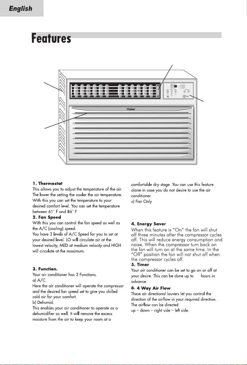
You can run the fan only on not so hot days. The
fan can be set to run at 3 speeds (HIGH fan, MED
fan, LOW fan)as desired by you.
You have 3 levels of Fan Speed to set at your
desired comfort level. HIGH, MED and LOW.
24
6
Page 8
The Fresh Air Vent allows the air conditioner to
recirculate inside air, draw fresh air into the room
and exhaust stale air to the outside .
12. Electrostatic Filter (not all models)
Being constructed of high efficiency purifying
substance, active carbon fabric, electrostatic fabric,
electrostatic active carbon net and other materials
it purifies the air effectively. Its wavy structure
increases the capability to filter dust and smoke
effectively. Due to the retention of the active carbon
it has a high purifying speed capable of
strong airflow.
13. How The Unit Drains
7
Page 9

Remote control and control panel operations
ON/OFF
MODE SPEED TIMER
TEMP/TIME
8
Page 10

Having set the temperature you will set the function of the air conditioner.
ON/OFF
MODE SPEED TIMER
TEMP/TIME
Every time you press the MODE button, it will change between FAN , COOL, ENERGY
SAVER and DEHUM. (See Fig. # 3)
9
Page 11

ON/OFF
MODE SPEED TIMER
TEMP/TIME
Once the function mode is decided you will have to set the fan speed.(See fig. #4)
Every time you press the SPEED button, fan speed will change between LOW,
HIGH,MED.
1) If you choose the COOL mode you can run the fan in one of the 3 speeds HIGH,
MED, LOW.
2) For cool days you may want to run the "FAN" function.
The fan can be set to run at
3 speeds (HIGH fan, MED fan, LOW fan)as desired by you.
3) If you choose to use the Dehumid function. This will remove excess moisture
from the air on excessively humid days.
Tr: temperature inside the room.
Ts: the set temperature.
1 ) When Tr>Ts+3 oF, the compressor will run continuously the fan at the
selected speed.
2)When Ts-1 oF*Tr*Ts+3 oF the compressor will cycle for 10 minutes on
and 6 minutes off.
3)When Tr<Ts-1 oF, the compressor will shut off.
The dehumidification process takes place between the set temperature -1
and 3 oF above the set temperature.
4)Energy Saver : The unit runs the same as COOL setting in the ENERGY SAVER
mode. But the fan will be off 3 minutes after the compressor cycle off.
10
Page 12

ON/OFF
MODE SPEED TIMER
TEMP/TIME
Timer on or Timer off mode is used to pre-start or shut off your unit in
advance. You can program this up to 24 hours in advance. You can use
the Timer in 4 functions i.e. COOL, Energy saver, Dehumid or Fan .
Timer on (See Fig. # 5)
Unit must be on to set the timer. Unit will shut down automatically after it
accepts the settings in 5 seconds. Use this mode to pre-set the start time of
the unit 24 hours in advance.
a) Press TIMER ON, LED display will show "XX" (time set last time) when power
is connected first time, LED display will show "01".
b) Set desired number of hours by pressing the ( ) pad of the Temp/Time
buttons, one for each hour. If you passed the desired time use the ( ) pad
key to lower the selection.
c) After set TIMER ON, LED display will show the time. This time displayed:
unit will starts after X hours.
Timer off (See Fig. # 5)
Unit must be running to set the timer off. Use this to preset the time you
would like the unit to shut off.
a) Press TIMER OFF, LED display will show "XX" (time set last time) when power
is connected first time, LED display will show "01".
b) Set desired number by pressing the ( ) pad of the Temp/Time buttons.
One for each hour. If you passed the desired time, use the ( ) pad key to
lower the selection.
c) After set TIMER OFF, LED display will show the room temperature about 5 seconds
later.
When using the timer the unit will use/revert to the last COOL and fan
settings when activated. The timer must be reset every time you choose to
use it.
11
Page 13

Fig. # 5
ON/OFF
MODE SPEED TIMER
TEMP/TIME
Adjusting the Air Flow Direction
Airflow can be adjusted by changing the direction of the air conditioner's louvers.
This can also increase the cooling efficiency of the air conditioner.
12
Adjusting Horizontal Air Flow
Direction
Adjusting the vertical louvers left and
right will change horizontal airflow.
Adjusting Horizontal Air Flow
Adjusting Vertical Air Flow Direction
Adjusting the Horizontal vane up and down will
change vertical airflow. The vane can be adjusted
by nudging the back or up and down of the vane.
Adjusting Vertical Air Flow
Recommended orientation of louvers
Adjust louvers to face upwards when cooling to maximize cooling efficiency.
Page 14

13
Page 15

Parts
Parts Supplied
window seal
gasket
curtain
attachment
screws 13/32"
wood screws 31/32"
19/32"long
basepan angle
installation bracket
(left and right)
Model:
HWR18VC5, HWR24VC5, ESA3156,ESAX3186, ESA3245,ESA3185
screw and
locknut
Remote
control
“CR2025“ battery
1/2
2
" long flat
head bolt and
locknut
top rail
left and right
curtains
side
14
Page 16

Installing Unit into A Window
Window Opening Requirements
The air conditioner is designed to fit into double or single hung sash type windows. Each of the
units comes with an installation kit that provides adjustable mounting louvers, to fill the gaps
between the sides of the unit, and the window frame. The chart below reflects the dimensions of
the units with, and without installation kits. Measure your window opening width and compare
it to the chart below to ensure that it meets the minimum and maximum window width requirements.
B
C
D
2
11
"
5
3
18
"
5
3
18
"
5
5
42
"
16
1
30
"
8
21
"
18
32
9
"
26
16
13
24
"
32
Model
Dimension
A(inch)
B(inch)
C(inch)
D(inch) Max
D(inch) Min
Case High
Case Width
Case Depth
A
HWR18VC5, HWR24VC5, ESA3156,ESAX3186, ESA3245,ESA3185
HWR18VC5,HWR24VC5,ESA3156,ESAX3186,ESA3245,ESA3185
Unpack unit on floor next to installation
location.
Remove two front attachment screws.
Separate the outer case from the front
with a putty knife at the catch points
designated by the arrows.
Remove the two screws on top of the
outer case.
Using the basepan handle, slowly and
evenly pull chassis out from outer case.
Note: Cover putty knife blade with
masking tape to guard against damage
of the unit finish.
Caution: Never expose plastic
front or grille to extreme
temperatures.
15
Page 17

ASSEMBLE
2
CURTAINS/TOP
RAIL
Install top rail with four screws.
Slide left-hand curtain assembly
into left end of top and bottom
rails. Repeat for right-hand curtain
assembly. Fasten curtain retainer
strips to sides of outer case with
six13/32" screws.
13/32"
PREPARE
3
WINDOW FOR
INSTALLATION
Inspect window track, sash, and sill
for its ability to support the weight of
air conditioner.
Measure width between window
moldings to ensure Instant Mount
will fit window frame. Instant Mount
models are designed for windows
wide (the detail see page 15)
Instant Mount kit supplied with unit
is designed for mounting in most
double-hungwindows without
storm windows.For installation in
window frame with storm window,
modify sill by adding wood strips(not
included)
to
inner and outer sills. This
unit and eliminates interference
raises
of
storm window frame.
Storm window installation
If storm window frame does not allow
adequate clearance below sill (1/2"
required), remove storm window
frame or create clearance by adding a
wood strip (at least 1 1/2" wide) along
entire width of sill. Fasten wood strip
to sill with at least three countersunk
wood screws (not supplied with kit).
This provides a smooth surface for
mounting air conditioner.
1/2"
1 1/2"
Minimum
Wood
SILL
I
N
D
O
O
R
Storm Window
Frame
Strip
Minimum
O
U
T
D
O
O
R
Mobile home window installation
Add wood strip (at least 1 1/2" wide)
along entire width of window sill.
Thickness of wood strip should match
height of front lip on window frame.
Fasten wood strip to sill with a
minimum of three countersunk wood
screws (not supplied with kit). This
provides a smooth surface for
mounting air conditioner.
Must be a minimum
of 1/2" to clear
bottom rail on unit
1 1/2"
Minimum
I
N
D
O
O
R
Wood
Strip
Window
Frame
O
U
T
D
O
O
R
16
Page 18

INSTALL OUTER
4
CASE IN WINDOW
Place outer case in window. Lower
sash until it rests behind front flange
of top rail. Bottom rail must rest
behind window sill.
T op rail
Bottom rail
Curtain assembly cut
away for clarity.
Use two wood screws 31/32" to fix the case to
windows sash. Install left & right installation bracket
and as shown in fig. Install bolt(2 1/2" long flat head
bolt and locknut) to the installation bracket and adjust
them to proper length ,then use 4 (19/32")screws to fix
the bracket on the case.
About
5°
Expand both curtains to contact the
window frame. Install four wood
screws 31/32". Two in each upper right and
left of the curtains.
Install three wood screws 31/32" top mounting rail
screws.
NOTE: To make screws easier to
drive, drill a pilot hole into sash
through clearance hole in curtains.
17
Page 19

INSTALL SASH BRACKET
5
& SEAL GASKET
Install sash bracket on top of indoor window sash
with one wood screw 31/32" to prevent raising of
window from the outside. Screw anchor directly into
side of window frame. For hard wood or metal window
frames, drill a pilot hole to start screw.
Important:Be careful not to drill pilot hole too deep.
Add a piece of tape to the drill bit as a depth gauge.
Also stay clear of glass. Be careful not to damage the
function of the window.
Cut window seal gasket to width of window. Stuff window
seal strip between outdoor window glass and top of
indoor sash. This will stop air leakage which reduces
efficiency.
6
Caution:
For security purpose, reinstall
screws at cabinet's sides, removed
in step one.
18
Page 20

Remove the 2 shipping screws on the top of the air conditioner
that hold the chassis to the outer shell casing.
19
Page 21

20
Page 22

Always unplug your air conditioner before cleaning.
The air filter behind the inlet grille should be checked and cleaned at least
once every 2 weeks (or as necessary) to maintain optimal performance of
the air conditioner.
How to remove the air filter
1. The grille may be opened from the top for easy maintenance after installation.
2. Open the inlet grille by pulling off the exposed door on the top of the
unit(based on the installation).
3. Pull the tab slightly to release the filter. Pull the filter in the same direction
as the opening.
4. Clean the filter with warm, soapy water. The water should be below
40oC(104oF).
5. Rinse off and gently shake off excess water from the filter. Let it dry before
replacing it.
DO NOT use your air conditioner without the air filter in place.
To clean the front panels or the cabinet DO NOT use harsh
chemicals, abrasives, ammonia, chlorine, bleach, concentrated
detergents, solvents or metal scouring pads.
Always use a soft cloth dampened with water or mild soap
and water solution to wipe the front if the cabinet.
21
Page 23

22
Page 24

(See page 8)
(See page 17)
23
Page 25

24
 Loading...