

Haier HDE5000AW, HDE5300AW, HDG5000AW, HDG5300AW, CHDE5000AW User Manual And Installation Instructions
...Page 1

User Manual and Installation Instructions
Gas & Electric Dryer
Sécheuses à chargement frontal à gaz et
électrique
Manual para el usuario e instrucciones
de instalación. Secadora a gas y eléctrica
Model #/ Modéle #/ Para Modelo de #
HDE/HDG5000AW ; HDE/HDG5300AW
Quality■Innovation■Style
(Picture for illustration purposes only. Actual model may vary per model purchased.)
Front Load Dryers
CHDE/HDG5000AW ; CHDE/HDG5300AW
Page 2

1
English
PAGE
IMPORTANT SAFETY INSTRUCTIONS.......................................2-4
INSTALLATION INSTRUCTIONS..............................................5-24
Tools and Materials Required............................................................ 5
Electrical Requirements ..................................................................5-6
Unpacking Your Dryer ..................................................................... 6
Exhaust System Requirements ........................................................7-8
Gas Supply Requirements ................................................................ 9
Location of Your Dryer ...................................................................10
Location of Your Dryer in a Closet.................................................... 11
Manufactured (Mobile) Home Instruction ......................................... 12
Procedure for Reversing the Door............................................... 13-17
Changing the Drum Light ................................................................18
Electrical Installation ...................................................................... 19
3-Wire Cord Connections ..............................................................20
4-Wire Cord Connections ..............................................................21
Gas Connections ..........................................................................22
Replacement Parts .........................................................................24
OPERATING INSTRUCTIONS ............................................... 25-38
Understanding the Control Panel
(HDE/HDG5300AW,CHDE/HDG5300AW)
....... 25-27
Understanding the Control Panel 27-29
Preparations before Drying .............................................................30
Load clothes into Dryer ................................................................... 31
Auto Dry Cycle
..........................
32-33
Auto Dry Cycle 34
Manual Dry Cycle 35
Manual Dry Cycle 36
Other Features............................................................................... 37
Normal Operating Sounds.............................................................. 38
CARE AND CLEANING GUIDE
.......................................................38
TROUBLESHOOTING.................................................................. 39
LIMITED WARRANTY .................................................................40
TABLE OF CONTENTS
(HDE/HDG5000AW,CHDE/CHDG5000AW)
.......
(HDE/HDG5300AW,CHDE/CHDG5300AW)
(HDE/HDG5000AW,CHDE/CHDG5000AW)
(HDE/HDG5300AW,CHDE/CHDG5300AW)
(HDE/HDG5300AW,CHDE/HDG5000AW)
..................................
..............................
..............................
Page 3

Page 4

English
WARNING - To reduce the risk of fire, electric shock, or
injury to persons when using your appliance, follow the
basic precautions, including the following:
1. Read all of the instructions before using this appliance.
2. Don’t dry articles that have been previously cleaned in, washed in,
soaked in, or spotted with gasoline, dry clean solvents or other
flammable explosive sub stains as they give off vapors which could
ignite or explode.
3. Do not allow children to play on or in the appliance. Close
supervision of children is necessary when the appliance is used near
children.
4. Before the appliance is removed from service or discarded, remove
the door to the drying compartment.
5. Do not reach into the appliance if the drum is moving.
6. Do not install or store this appliance where it will be exposed to
water and/or to the weather.
7. Do not tamper with controls.
8. Do not repair or replace any part of the appliance or attempt any
servicing unless specifically recommended in the user-repair
instructions that you understand and have skills to carry out.
9. Do not use fabric softeners or products to eliminate static unless
recommended by the manufacturers of the fabric softener or
product.
10. Do not use heat to dry articles or products to eliminate static unless
recommended by the manufacturers of the fabric softener or
product.
11. Clean lint screen before or after each load.
12. Keep area around the exhaust opening and adjacent surrounding
areas free from the accumulation of lint, dust and dirt.
13. Keep the dryer area clear and free from items that would obstruct
the flow of combustion and ventilation air through the louvered panel
located on the rear of the dryer.
14. The interior of the appliance and the exhaust duct should be cleaned
periodically by qualified service personnel.
3
IMPORTANT SAFETY
INSTRUCTIONS
Page 5

English
4
Thank you for using our Haier
product. This easy-to-use manual
will guide you in getting the best
use of your dryer.
Remember to record the model and
serial number. They are on a label
in back of the dryer.
Model number
Serial number
Date of purchase
Staple your receipt to your manual.
You will need it to obtain warranty service.
15. Do not place items exposed to cooking oils in your dryer. Items
contaminated with cooking oil may contribute to a chemical reaction
than could cause a load to catch fire.
16. If material has been used with any flammable liquids or solids, it
should not used in the dryer until all traces of flammable liquids and
its fumes have been removed.
17. This dryer must be properly installed in accordance with the
installation instructions before it is used. See grounding instructions in
the installations sections.
18. Proper grounding must be ensured to reduce the risk of electric shock
and force. Check with a qualified electrician or service personnel if
you are in doubt as to whether the dryer is properly grounded.
19. Use the dryer only for its intended purpose: drying clothes.
20. Always disconnect dryer from electrical supply before attempting any
service. Disconnect power cord by grasping the plug, not the cord.
21. Replace worn power cord and/or loose plugs.
22. To reduce the risk of electric shock or fire, do not use extension cords
or adapters to connect dryer electrical power source.
Risk of child entrapment. Before you throw away your old dryer,
take off the door so that children may not get trapped inside.
SAVE THESE
INSTRUCTIONS
DANGER
Page 6

5
WARNING
Risk of Fire:
Tools and materials required
• Phillips-Head and flathead screwdrivers
• Channel-lock adjustable pilers
• 1/2-inch open-end wrench
• Carpenter’s level
• Measuring tape (12ft. min.)
• Duct tape
• Pipe thread sealer (Gas)
• Rigid or flexible metal 4 inch (102cm) duct
• Vent hood
Safety Warning:
1. Before starting installation, make sure that the gas shut off valve is in the
off position.
2. All old gas connectors and gas piping should be discarded.
ELECTRICAL REQUIREMENTS
Electric Dryer:
(CHDE/HDE5000AW
and
CHDE/HDE5300AW)
Circuit
Individual 30 Amp branch circuit fused with 30 Amp time-delay fuses or circuit
breakers. Use seperately fused circuits for washers and dryers, and DO NOT
operate a washer and dryer on the same circuit.
INSTALLATION INSTRUCTIONS
English
1.Clothes dryer installation must be performed by a qualified installer.
2.Install the clothes dryer according to the manufacturer’s instructions
and local codes.
3.Do not install a clothes dryer with flexible plastic venting materials.
If flexible metal (foil type) duct is installed,it must be of a specific
type identified by the appliance manufacturer as suitable for use
with clothes dryers. Flexible venting materials are known to collapse,
be easily crushed,and trap lint.These conditions will obstruct clothes
dryer airflow and increase the risk of fire.
4.To reduce the risk of severe injury or death, follow all installation
instructions.
SAVE THESE INSTRUCTIONS
Page 7

English
6
Power Supply
3 or 4 wire, 120/240 Volt, 1 Phase, 60Hz, AC
(Canada - 120/240 Volt, 1 Phase, 60 Hz, AC)
Power Supply Cord Kit
(Not supplied when sold in US. Must be purchased to meet local electrical
codes.) The dryer MUST employ a 3-conductor power supply cord NEMA 10-30
Type SRDT rated at 240 Volt AC minimum, 30 Amp, with 3 open end spade lug
connectors with upturned ends or closed loop connectors and marked for use
with clothes dryers.
(When sold in Canada - 4-wire power supply cord provided and
attached on dryer)
Dryers being installed in a manufactured (mobile) home MUST employ a
4-wire power supply cord NEMA 14-30 type SRDT or ST (as required) rated
to 240 Volt AC minimum, 30 Amp, with 4 open-end spade lug connectors
with upturned ends or closed loop connectors and marked for use with clothes
dryers. See Electrical Connections for more information on a 4-wire system.
Outlet Receptacle
NEMA 10-30R receptacle should be located so the power supply cord is
accessible when the dryer is in the installed position. (Canada - NEMA 14-30R
receptacle)
ELECTRICAL REQUIREMENTS
Gas Dryer: (CHDG/HDG5000AW and CHDG/HDG5300AW)
Circuit
Individual 15 Amp branch circuit fused with 15-Amp maximum time delay fuse
or circuit breakers.
Power Supply
3 wire, 120 Volt, 1 Phase, 60Hz, AC
Power Supply Cord
The dryer is equipped with a 120 Volt 3-wire power supply cord.
NOTE: This dryer is equipped with a three-prong grounding plug for your
protection against shock hazard and should be plugged into a properly
grounded three-prong receptacle. Do not under any circumstance cut or
remove grounding prong from plug.
Unpacking Your Dryer
1. Remove all packaging material. This includes the foam base and all adhesive
tape holding the dryer accessories inside and outside.
2. Inspect and remove any remains of packaging, tape or printed materials
before using the dryer.
Page 8

The following are specific requirements for
proper and safe operation of your dryer. Failure
to follow these instructions can create excessive
drying times and fire hazards.
1. Do not use plastic flexible duct to exhaust the dryer. Excessive lint can build up
inside exhaust system and create a fire hazard and restrict air flow. Restricted
air flow will increase drying time. If your present system is made up of plastic
duct or metal foil duct, replace it with a rigid or flexible metal duct. Ensure
present duct is free of any lint prior to installing dryer duct.
2.
The dryer shall not be exhausted into a chimney, a wall, a ceiling, an attic, a
crawl space, or a concealed space of a building;
The dryer exhaust system
MUST be
exhausted to the outdoors. If the dryer is not exhausted
outdoors, some
fine lint will be expelled into the laundry area. An accumulation
of lint in any
area of the home can create a health and fire hazard.
3. Exceeding the length of duct pipe or number of elbows allowed in the
“Maximum Length” chart can cause an accumulation of lint in the exhaust
system. Plugging the system could create a fire hazard, as well as increase
drying times.
4. Do not screen the exhaust ends of the vent system. Lint can become caught in
the screen, increasing drying time. Use an approved vent hood to terminate the
duct outdoors, and seal all joints with duct tape.
5. All male duct pipe fittings must be installed downstream with the flow of air.
6. The duct shall not be assembled with screws or other fastening means that extend
into the duct and catch lint.
7. Do not allow combustible material (clothing, draperies/curtains, paper, etc.) to
come in contact with exhaust system.
Explosion hazard:
Do not install the dryer where gasoline or other flammables are kept or
stored. If the dryer is installed in a garage, it must be a minimum of 18
inches (45.7cm) above the floor. Failure to do so can result in death,
explosion, fire or burns.
Exhaust Requirements:
Use only rigid or flexible metal duct and
approved vent hood which has a
swing-out
damper hat open when the dryer is
in operation. When the dryer
stops, the dampers automatically close to prevent
drafts
and the entrance of
insects and rodents. To avoid restricting the outlet,
WARNING
EXHAUST SYSTEM REQUIREMENTS
English
7
maintain a minimum of
Page 9
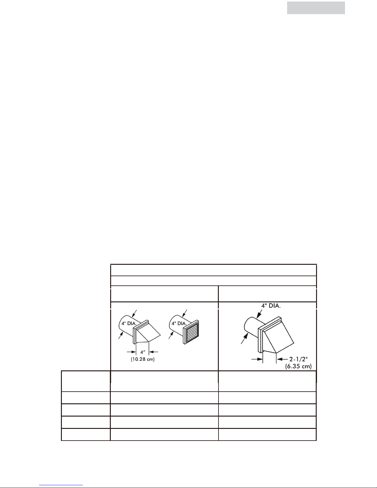
clearance between the vent hood
and the ground or
any other obstruction. The vent flap should be able to move
freely, although
vertical orientation of the exhaust system is acceptable. Certain
extenuating
circumstances could affect the performance of the dryer:
1. Only rigid or flexible metal duct work should be used.
2. Venting vertically through a roof may expose the exhaust
system to down
drafts causing an increase in vent restriction.
3. Running the exhaust system through an uninsulatedarea may
cause
condensation and faster accumulation of lint.
4. Compression of crimping of the exhaust system will cause
an increase in
vent restriction.
The exhaust system should be inspected and cleaned a minimum of every 12
months with normal usage. The more the dryer is used the more often you
should check the exhaust system and vent hood for proper operation.
Side and Bottom Exhaust
For your convenience, your dryer can be exhausted through the side or the
bottom. If you need to change the exhaust on the dryer to the side or the
bottom of the cabinet, you will need to order the exhaust kit from your Haier
dealer or call 1- 800-313-8495
English
RECOMMENDED MAXIMUMM
Exhaust Hood Types
Recommended
Use only for short
run installations
No. of 90º
elbows
Rigid Metal Rigid Metal
0 90 ft. 60 ft.
1 60 ft. 45 ft.
2 45 ft. 35 ft.
3 35 ft. 25 ft.
12 inches (30.5cm)
The total length of flexible metal duct shall not exceed 2.4 m.
5. In Canada, that only those foil-type flexible ducts, if any, specifically identified
for use with the appliance by the manufacturer shall be used. In the United
States, that only those foil-type flexible ducts, if any, specifically identified for
use with the appliance by the manufacturer and that comply with the UL Outline
for Clothes Dryer Transition Duct, Subject 2158A (2006), shall be used.
6. In Canada, that the exhaust duct shall be 102 mm in diameter. In the United
States, the required exhaust duct diameter.
8
Page 10

GAS SUPPLY REQUIREMENTS
English English
9
ADVERTENCIA
ADVERTISSMENT
Replace copper connecting pipe that is not plastic
coated. Stainless steel or plastic-coated brass
MUST be used.
1. Installation MUST conform with local codes. In the absence of local codes,
installation must conform with the National Fuel Gas Code, ANSI Z223.1 (latest
edition) or in Canada, the current CAN/CGA B149.1
2.
The gas supply line should be 1/2 inch (1.27cm) pipe.
3.
If codes allow, flexible metal tubing may be used to connect your dryer to the
gas supply line. The tubing MUST be constructed of stainless steel or plasticcoated brass.
4.
The gas supply line MUST have an individual manual shutoff valve installed
within 6 feet (183cm) of the dryer in accordance with the National Fuel Gas
Code, ANSI Z223.1/NFPA 54.
In Canada, an individual manual shut-off valve MUST be installed in
accordance with the B149.1, Natural Gas and Propane Installation Code.
5. A 1/8 inch (0.32cm) N.P.T. plugged tapping, accessible for test gauge
connection, MUST be installed immediately upstream of the gas supply
connection to the dryer.
6. The dryer MUST be disconnected from the gas supply piping system during
any pressure testing of the gas supply piping system at test pressures in excess
of 1/2 psig (3.45kPa).
7.
The dryer MUST be isolated from the gas supply piping system during any
pressure testing of the gas supply piping system at test pressures equal to or
less than 1/2 psig (3.45 kPa).
Page 11

English
10
Do Not Install Your Dryer:
1. In an area exposed to dripping water or outside weather conditions.
2. In an area where it will come in contact with curtains, thick carpet, or anything
that will obstruct the flow of combustion and ventilation air.
3. On carpet, floor must be solid with a maximum slope of 1inch (2.54 cm). Any
floor unevenness should be corrected with leveling legs located on the bottom
of the dryer.
Installation in Alcove or Closet:
1. DO NOT install your dryer in a closet with a solid door.
2. A dryer installed in a bedroom, bathroom, alcove or closet MUST be
exhausted outdoors.
3. No other fuel burning appliance shall be installed in the same closet as the
gas dryer.
4. Refer to the images on this page to ensure the installation provides the
minimum amount of clearance required for ventilation.
5. When installing the dryer in a closet with a door, a minimum of 120 square
inches (774.2 square cm) of ventilation in the door is required. Openings must
be equally divided at the top and bottom of the door and airflow must be
unobstructed. A louvered door with equivalent air openings for the length of
the door is acceptable.
LOCATION OF YOUR DRYER
8
2
5
m
m
6
8
6
m
m
1010mm
1295mm(51”)
960mm(37-13/16“)
39-3/4”
2
7
”
3
2
-
1
/
2
”
Page 12

English
Following are instructions concerning and the minimum clearances required for
any closet, recessed area, or customized under-counter installation:
• Additional distances facilitate installation and servicing.
• Addtional clearances might be required for wall, door and floor moldings.
• Additional distances of 1 in. (25.4mm) on all sides of the dryer is
recommended to reduce noise transfer.
• For closet installation with a door, minimum ventilation openings in the top
and bottom of the door are required. Louvered doors with equivalent ventilation
openings are acceptable. Companion appliance spacing should be
considered.
LOCATION OF YOUR DRYER IN A CLOSET OR RECESSED AREA
11
32.5"
1 5 "
1
"
0
"
( 5. 4m m )
2
( 0 mm )(8 25m m)
( 3
8
.1
mm)
3"
(76m m )
3"
(76m m )
60"
2
( )
387. 1 c m
2
60"
2
( )
387. 1 c m
2
Page 13

English
12
1. Dryer MUST be exhausted outside (outdoors, not beneath the manufactured
home) using metal ducting that will not support combustion. Metal ducting must
be 4 inch (10.16 cm) in diameter with no obstructions. Rigid metal duct
is preferred.
2. If dryer is exhausted through the floor and area beneath the manufactured
home is enclosed, the exhaust system MUST terminate outside the enclosure
with the termination securely fastened to the mobile home structure.
3. When installing a gas dryer into a manufactured home, a provision must be
made for outside make up air. This provision is to be not less than twice the
area of the dryer exhaust outlet.
4. This dryer MUST be fastened to the floor using P/N 0030807899
Manufactured Home Installation Kit. Follow the instructions supplied with
the kit.
5. Refer to previous sections for other important venting requirements.
6. Installation must conform to current Manufactured Home Construction & Safety
Standard (which is a Federal Regulation Title 24 CFR-Part 32-80) or when
such standard is not applicable, with American National Standard for Mobile
Homes. In Canada, the CSA Z240 is applicable.
MANUFACTURED (MOBILE) HOME INSTALLATION
Page 14

English
Before you reverse the door, place a soft cloth
on the work space to protect the surface of the
door.
1. Open the dryer door.
2. Using the long phillip screw driver,
remove the left one screw from the hinge
that attach the dryer door to the front
panel of the dryer. (Fig 1)
3. Using the long phillip screw driver,
remove the right 2 screws from the hinge
that attach the dryer door to the
front panel of the dryer. (Fig 2)
Note: While removing the door screws,
the screwdriver must be straight. Screws
may not come off if screw driver is at an
angle.
4. To disengage the door from the panel,
hold the door close to the hinge and lift
straight up. (There are 3 tabs in the back
of the hinge that will be disengaged).
(Fig 3)
The door on your dryer can be changed from a right-side opening to a leftside opening, if you need.
Tools required: 1. Long magnetic head
phillip screw driver
2. Power Drill
13
Fig 1
Fig 2
Fig 3
NOTE: Be careful while removing the door. Lift
with caution or door hinge tab may break.
PROCEDURE FOR REVERSING THE DOOR
Page 15

English
5. Lay the door on a soft surface to protect
the door surface with the glass facing up,
remove the 8 screws using the power drill
holding hinge cover and strike
panel. (Fig 4)
6. Remove the hinge cover, then remove
the 8 screws which hold the hinge knots
“B” “T”. (Fig 5 and Fig 6)
1413
Fig. 5
Fig. 6B
Fig. 6A
Fig. 4
Strike Panel
Hinge Cover
NOTE: If hinge knots (T & B) are not properly placed the
hinge cover may not align with the door.
Page 16
English
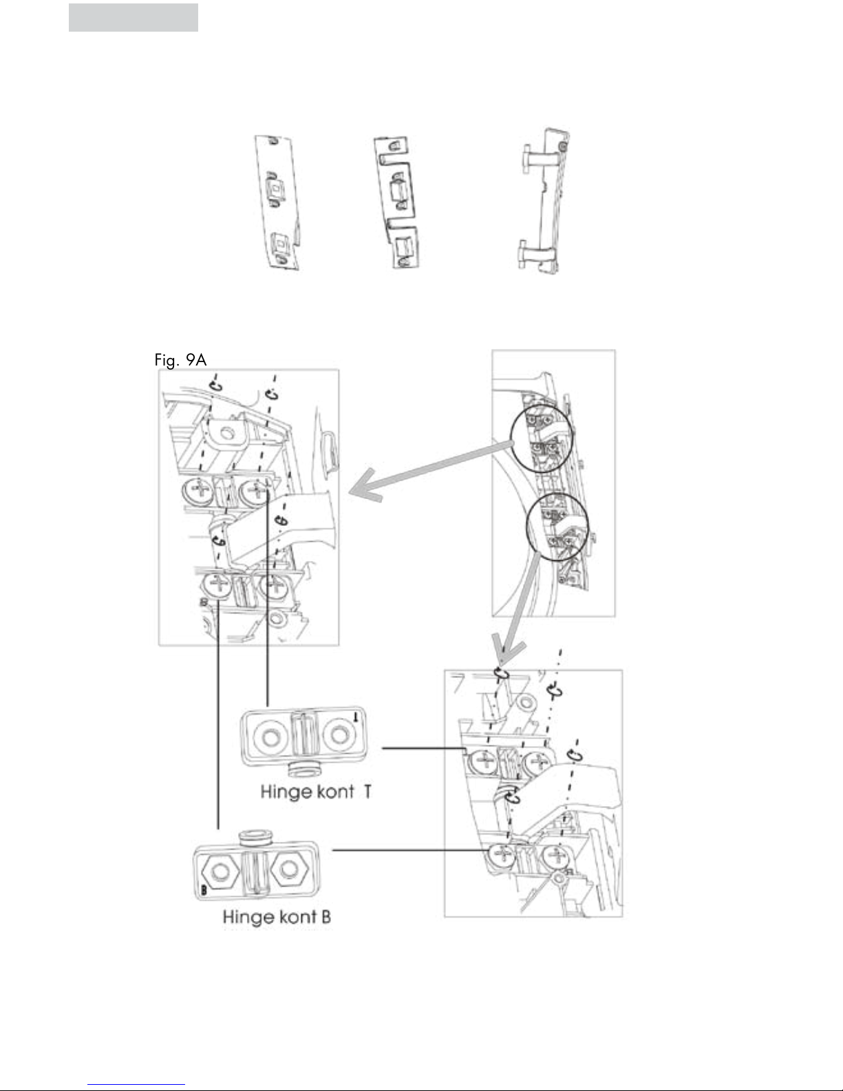
7. There are 3 parts included which are symmetrical to the 3 removed parts
(Fig 7)
A
Fig. 7
Fig. 9A
B
C
8. On the opposite side first install the hinge (Fig 7C) to the door using Top
and Bottom Hinge Knot “T” and “B”. (Fig 9A and 9B)
Fig. 8
Fig. 9B
Note: Be careful not to get the top and bottom hinge knots mixed up.
Page 17

English
10. Remove the 3 plastic plugs located outside the dryer door opening. Install the
3 plastic plugs into the hinge holes in the dryer front panel on the right side.
(Fig 11A and 11B)
9. Now install both the hinge cover and the strike panel (Fig. 7A and 7B) to the
door as shown in Fig. 10. Use the same 8 screws that were earlier removed
Be carefull not to strip during tightening the screws.
1615
Fig. 10
B
A
Fig. 11
Page 18

11. To hang door, place hinge tab’s against the 3 holes on the front panel left
side. Press down to engage the tab’s and line up the 3 holes.
(Fig 12A and 12B).
12. Install 2 left screws but do not tighten, then install 1 right screw and tighten.
Now tighten the 2 left screws. (Fig 13)
13. Close door to make sure it is aligned.
English
17
A
A
B
B
Fig. 12
Fig. 13
Page 19
English
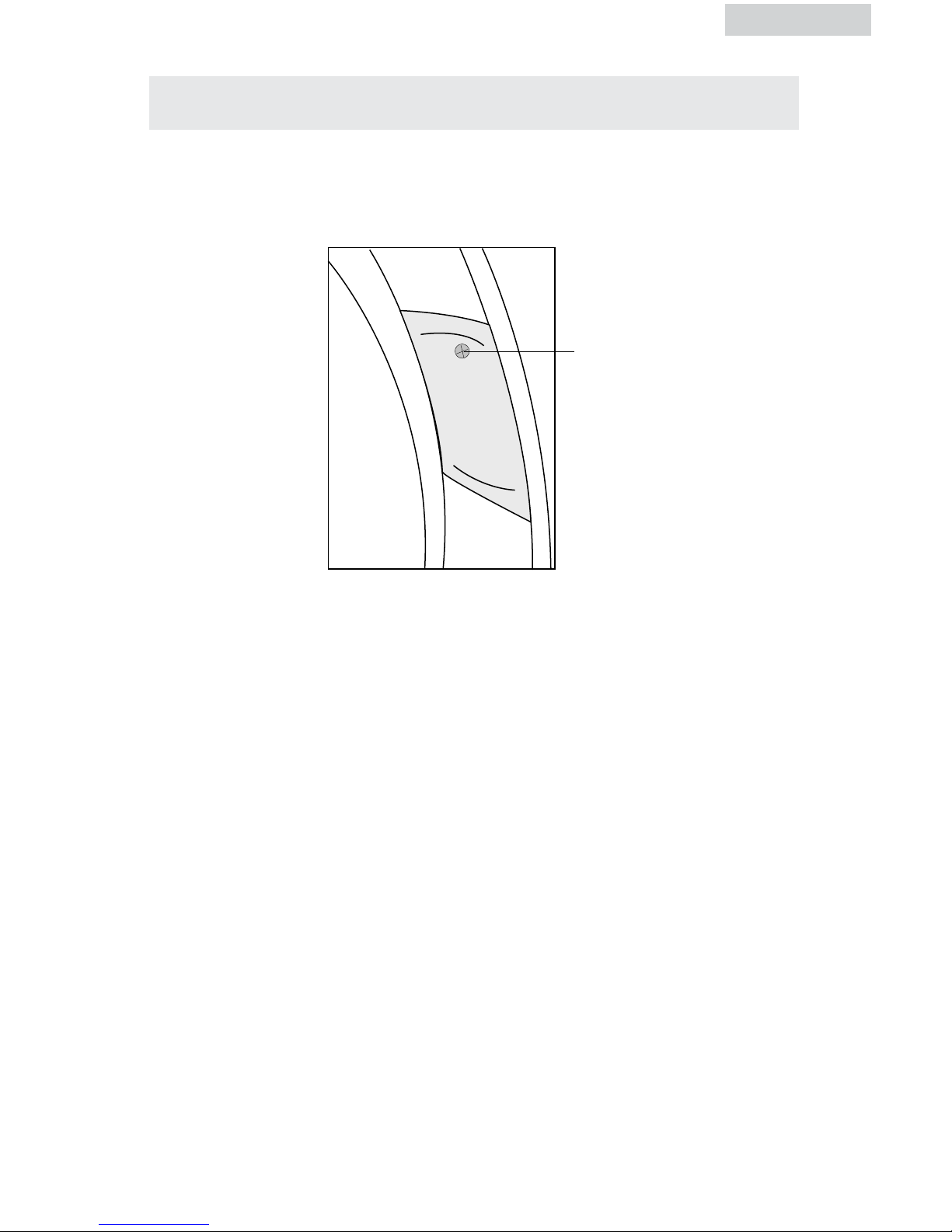
1. For your safety, please unplug the power cord before changing the drum light.
2. Open the dryer door, find the location of the drum light. Using a phillip head
screw driver remove the light cover (as shown below).
3. Remove the bulb by turning it counterclockwise. Replace the bulb with a
10-watt lamp only, then install the cover and tighten the screw.
4. Use your dryer after plugging it in the electrical socket.
CHANGING THE DRUM LIGHT
18
Screw
Page 20

English
The following are specific requirements for proper
and safe electrical installation of your dryer.
Failure to follow these instructions can create
electrical shock and/or fire hazard.
WARNING
1. This appliance must be properly grounded. Electrical shock can result if the
dryer is not properly grounded. Follow the instructions in this manual for
proper grounding.
2. Do not use an extension cord with this dryer. Some extension cords are not
designed to withstand the amounts of electrical current this dryer utilizes and
can melt, creating electric shock and/or fire hazard. Locate the dryer within
reach of the receptacle for the length power cord to be purchased, allowing
some slack in the cord. Refer to the electrical requirements in this manual for
the proper power cord to be purchased.
3. A UL approved strain relief must be installed onto power cord. If the strain
relief is not attached, the cord can be pulled out of the dryer and can be cut
by any movement of the cord, resulting in electrical shock.
4. Do not use an aluminum wire receptacle with copper-wired power cord and
plug (or vice versa ). A chemical reaction occurs between copper and
aluminum and can cause electrical shorts. The proper wiring and receptacle
is a copper-wired power cord with a copper-wired receptacle.
NOTE: Dryers operating on 208 Volt power supply will have longer drying times
than operation on 240 Volt power supply.
Improper connection of the equipment grounding conductor can
result in a risk of electrical shock. Check with a licensed
electrician if you are in doubt as to whether the appliance is
properly grounded.
1. Gas dryers are equipped with a factory installed three-prong 15 Amps ~120
Volts (grounding) plug for your protection against shock hazard and should be
plugged directly into a properly grounded three-prong receptacle. Do not cut
or remove the grounding prong from this plug.
ELECTRICAL INSTALLATION
ELECTRIC Dryer (CHDE/HDE5000AW and CHDE/HDE5300AW)
GAS Dryer (CHDG/HDG5000AW
and
CHDG/HDG5300AW)
19
GROUNDING INSTRUCTIONS
This appliance must be grounded. In the event of malfunction or breakdown,
grounding will reduce th risk of electric shock by providing a path of least
resistance for electric current. This appliance is equipped with a cord having an
equipment-grounding conductor and a grounding plug. The plug must be plugged
into an appropriate outlet that is properly installed and grounded in accordance
with all local codes and ordinances. This appliance must be connected to a
grounded metal, permanent wiring system, or an equipment-grounding conductor
must be run with the circuit conductors and connected to the equipment-grounding
terminal or lead on the appliance.
Page 21

English
3-Wire System (US models only)
1. Remove the screws securing the terminal block access cover and the strain
relief mounting bracket located on the back of the dryer’s upper corner.
2.
Install a U.L. approved strain relief into the power cord entry hole of the
mounting bracket. Finger tighten the nut only at this time.
3. Thread a U.L. Approved 30 Amp. Power cord, NEMA 10-30 Type SRDT,
through the strain relief.
4. Attach the power cord neutral (center wire) conductor to the brass colored
center terminal on the terminal block. Tighten the screw securely.
5. Attach the remaining two power cord outer conductors to the outer brass
colored terminals on the terminal block. Tighten both screws securely.
WARNING: Do not make a sharp bend or crimp wiring/conductor at
connections.
6. Reattach the strain relief mounting bracket to the back of the dryer with two
screws. Tighten screws securely.
7. Tighten the screws securing the cord restraint firmly against the power cord.
8. Tighten the strain relief nut securely so that the strain relief does not turn.
9. Reinstall the terminal block cover.
ELECTRICAL CONNECTIONS
ELECTRIC Dryer (HDE5000AW and HDE5300AW)
20
Page 22
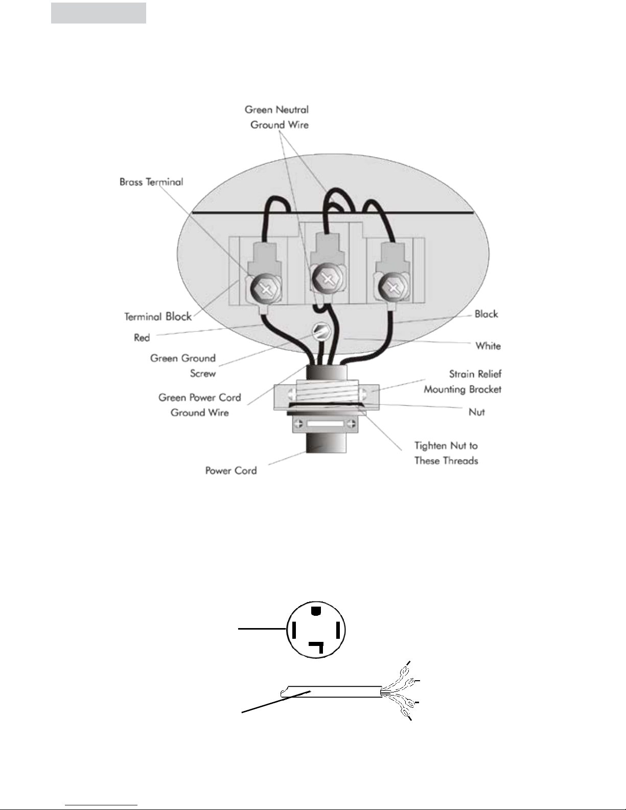
4-Wire Cord Connections(US models only)
1. Remove the screws securing the terminal block access cover and the strain
relief mounting bracket located on the back of the dryer upper corner.
2. Install a UL approved strain relief into the power cord entry hole of the
mounting bracket . Finger tighten the nut only at this time.
3. Remove the green neutral ground wire from the green ground screw located
above the terminal block.
Black 240V
White Neutral
Red 240V
Green Ground
Typical Conductor
Receptacle
Typical 4
Conductor Cord
ELECTRIC Dryer
(HDE5000AW
and
HDE5300AW)
English
21
Page 23

English
4. Thread a U.L. approved 30 Amp power cord. NEMA 14-30 type ST or SRDT
through the strain relief.
5. Attach the green power cord ground wire to the cabinet with green ground screw.
6. Attach the green wire conductors from the dryer and the white (neutral) power cord
conductors to the brass-colored center terminal on the terminal block. Tighten the screw
securely.
7. Attach the red and black power cord conductors to the outer brass-colored terminals on
the terminal block. Tighten the screw securely.
Warning: Do not make a sharp bend or crimp the wiring /conductor at connections.
8. Tighten the screws securing the cord restraint firmly against the power cord.
9. Tighten the strain relief nut securely so that the strain relief does not turn.
10. Reinstall the terminal block cover.
NOTE: DO NOT connect the dryer to L.P. gas service without converting the
gas valve. An L.P. Conversion Kit must be installed by a qualified
gas technician.
1. Remove the shipping cap from gas pipe at the rear of the dryer.
2. Connect a 1/2 inch (1.27cm) I.D. semi-rigid or approved pipe from gas supply line to
the 3/8 inch (0.96cm) pipe located on the back of the dryer. Use a 1/2 inch to 3/8
inch (1.27cm to 0.96cm) reducer for a connection. Apply an approved thread sealer
that is resistant to the corrosive action of liquified gases on all pipe connections.
3. Open the shutoff valve in the gas supply line.
4. Test all connections by brushing on a soapy water solution. NEVER TEST FOR GAS
LEAKS WITH AN OPEN FLAME.
5. Connect the exhaust duct to the outside exhaust system. Use duct tape to seal all joints.
6. With the dryer in its final position, adjust one or more of the legs until the dryer is resting
solid on all four legs. Place a level on top of the dryer. THE DRYER MUST BE LEVEL
AND RESTING SOLID ON ALL FOUR LEGS.
7. Plug the power cord into a grounded outlet.
NOTE: check to ensure power is OFF at
circuit breaker/fuse box before plugging
the power cord into the outlet.
8. Turn on the power at the circuit breaker/fuse box.
CAUTION
Before operating the dryer, make sure the dryer area is clean and
free from combustible materials, gasoline, and other flammable
vapors. Also see that nothing (such as boxes, clothing, etc.) obstructs
the flow of combustion and ventilation air through the louvered
panel located on the rear of the dryer.
9. Run the dryer through a cycle check for proper operation.
NOTE: On gas dryers, before the burner will light, it is necessary for the gas line to be
bled of air. If the burner does not light within 45 seconds the first time the dryer is
turned on, the safety switch will shut the burner off. If this happens, turn the dryer to
“OFF” and wait 5 minutes before making another attempt to light.
NOTE: Follow instructons supplied with kit.
GAS CONNECTIONS
GAS Dryer (HDG5000AW and HDG5300AW)
22
Page 24
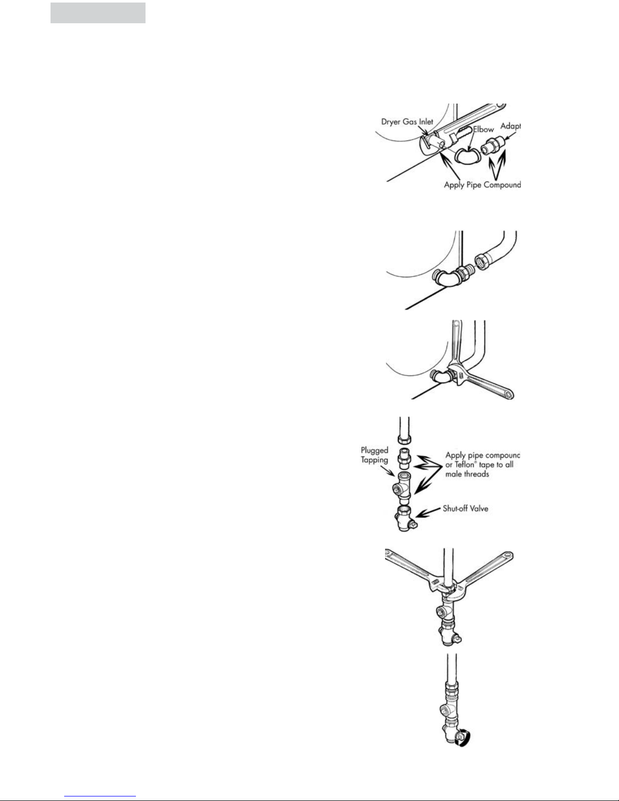
A) Connect female 3/8” NPT elbow to gas
inlet on dryer. Then connect 3/8” flare
union adapter to female elbow.
IMPORTANT: To prevent the inlet from
twisting, please use a pipe
wrench to secure the dryer
gas inlet. Affix Teflon®
tape or pipe compound to
adapter and gas inlet.
B)
Attach the flexible metal gas line connector
to the adapter.
C) Make sure flexible gas line seal is secure.
Use two wrenches for the best possible
connection.
D) To check gas inlet pressure, attach 1/8”
NPT plugged tapping to dryer gas line shutoff valve. Then connect flare union adapter
to plugged tapping. Affix Teflon® tape
to the threads of the adapter and plugged
tapping to ensure seal.
E)
Use two adjustable wrenches to tighten
every connection.
IMPORTANT: Do not overtighten!
F) Open gas shut-off valve.
CONNECTING THE DRYER TO THE GAS SUPPLY
English English
Page 25

REPLACEMENT PARTS
Replacement parts and accessories for US and Canada can be purchased
through Haier America at 1-800-313-8495
WARNING
ADVERTENCIA
ADVERTENCIA
ADVERTISSMENT
PRECAUCIÓN
ATTENTION
CAUTION
Label all wires prior to disconnection when servicing
controls. Wiring errors can cause improper and dangerous
operation. Check unit for proper operation after servicing.
ADVERTENCIA
ADVERTISSMENT
Discard or destroy the carton and plastic bags after the
dryer is unpacked. Children should not be allowed to use
them to play with. Cartons covered in rugs, bedspreads or
plastic sheets can become an airtight chamber and cause
suffocation leading to death. Make all packing materials
inaccessible to children.
ADVERTENCIA
ADVERTISSMENT
The instructions in this manual and all other literature
included with this dryer can not cover every possible
condition and situation that may occur. Good safe practice
and caution must be applied when installing, operating,
and maintaining any appliance. If you are in doubt after
installing, call a certified electrician to install and wire the
dryer.
2423
Page 26

English
Understanding the Control Panel
HDE/HDG5300AW,CHDE/CHDG5300AW
NOTE: Features may vary per model.
Power On/Off Button: (1)
• Touch the button to power dryer on. To power off, touch the button for 2
seconds.
Start/Pause Button: (2)
• hcuoT the
button for 1 second
to turn the dryer ON. Touch this to start
the dry
process. Touch this again to pause the activity
during the dry
cycle.
Manual Dry Cycles Dial: (3)
• The “Manual Dry Cycles” button will let you select a specific amount of drying
time and a drying temperature. In this selection the remaining time on display
shows the actual time remaining in the cycle. The actual time can be changed
in the cycle by touching “More Time” or “Less Time” buttons.
- Speed Dry: Use for small loads that need a short drying time.
- Rack Dry: Used for items that should not tumble E.g. Sweaters, silk, lingerie
or sneakers.
- Timed Dry: Use this cycle to dry heavy weight items like bedspreads, etc.
- Touch Up: This cycle removes wrinkles from items such as clothes packed in
a suitcase or wrinkles in items from being left in the dryer too long.
Auto-Dry (Sensor Dry) Cycles Dial: (3)
• yrD-otuA“ (Sensor Dry) cycles” button will let you select your desired dry
cycles. For your convenience, there are 6 fabric care dry cycles programmed
in this mode: Bulk Items, Heavy, White, Normal, Delicate, Press Free. A sensor
detects the moisture in the load and automatically adjust the drying time for
optimum drying.
OPERATING INSTRUCTIONS
25
To reduce the risk of fire, electric shock, or injury to persons,
read all of the IMPORTANT SAFETY INSTRUCTIONS before
using this appliance.
button
button for 1 second
1
2
3
4
5
6 7
8 9
10
11
12 13
Page 27

English
Dry Level Button: (4)
• desU to set drying level of auto-programs. If no auto-program is selected,
touching the button will cause a chime to sound. There are 5 selections: Very,
More, Normal, Less, Damp. First select sensor dry cycle then adjust the dry
level to how much you want to dry the load. The dryer will adjust the time
based on the selected dry level.
Note: Dry level selection can only be made while using the Auto (Sensor) Dry
Cycles.
Temperature Button: (5)
• desU to set drying temperature. There are 5 available drying temperatures:
High, Medium, Low, Extra Low and Air Dry (No heat).
NOTE: In rack dry cycle the temperature selection is limited to Extra Low and
Air Dry.For atuo dry cycles ,the temperature can not be selected.
Signal Button: (6)
• stceleS buzzing volume or turns off the buzzer. You can choose loud, soft, or
off. This controls the volume of beep when you touch any buttons on the control
panel.
Digital Display (7)
• Indicates the remaining time (min) during cycle operation.
Note: If the dryer has any problems, it will display an error message.
Anti Bacterial (8)
• This function can be selected only in certain cycles. Here the heat temp is
raised to the highest dry level. This option can only be used with heavy, bulky
items, white and normal cycle.
Note: Do not use on delicate fabrics
Wrinkle Saver Button: (9)
• sihT convenient feature helps keep wrinkles from setting when you cannot
unload the dryer at the end of a cycle. The dryer will stop and then tumble for
a brief period every few minutes. Press the wrinkle saver button to activate. This
feature will work for 1 hour after the drying program is completed. Stop the
setting at any time by opening the dryer
door.
More Time & Less Time Button: (10)
• desU to set time from 0 to 2 hours when Timed Dry, Rack Dry or Speed Dry
cycle is selected.
Damp Dry Signal (11)
• If activated the dryer will beep when the load is 80% dry. This will allow you to
remove light weight or other items that you may wish to iron.
Normal Use to select normal clothes worn in daily use
Heavy Heavy weight material such as jeans or bath towels.
White For clothes such as linens and sheets.
Bulky Items Drying bulky clothing, such as bed sheets.
Press Free For wrinkle-free, permanent press, and knits.
Delicate Drying small quantity clothes and delicate fabric.
26
Page 28

English
Custom Program: (12)
•
This allows you to save a favorite cycle,set the desired settings and touch
“custom program”button for 3 seconds. A beep will sound to indicate the
cycle has been saved.
To recall your custom cycle ,touch the “custom program”button before drying
a load.
To change the saved cycle,set the desired settings and “custom program”button
for 3 seconds.
You can also program Anti-Bacterial, Wrinkle Saver and
Damp Dry Signal.
Touch custom program and touch start/pause button to
activate.
Status Indicator: (13)
- Child Lock:
You can lock the controls to prevent any selections from being
made.Or you can lock the controls after you have started a cycle.
Children cannot accidentally start the dryer by touching pads
with this option selected.
To lock the dryer,touch and hold “Damp Dry Signal”for 3 seconds.
Asingle beep tone is heard and Child Lock is glow.To unlock the
dryer,touch and hold the “Damp Dry
Signal”for 3 seconds.
- Check Filter:
After the power button is touched,the check filter indicator could
flashes until Start/Pause is selected.
This is a reminder to clean the lint filter before the dry
program starts.
-Dry: When lit this indicates the process the cycle is currently in.
- Cool Down: When lit this indicates the process the cycle is currently in.
Understanding the Control Panel
HDE/HDG5000AW
NOTE: Features may vary per model.
Power On/Off Button: (1)
• Press the button to power on the dryer. To power off press button again.
Cycle Selection: (2)
• tceleS from the Auto Dry cycles (Bulky Items, Heavy, White, Normal, Delicate
and Press Free) or Manual Dry cycles (Touch Up, Timed Dry, Rack Dry or
Speed Dry).
English
27
1
2
3
4
5
6
7
10
11
12
13
8
9
13
Page 29

English
Start/Pause Button: (3)
• Press the button to turn the dryer ON. Press this button once to start the dry
process. Press this button once again to pause the activity during the dry
cycle.
Dry Levels: (4)
• Used to set drying levels of auto programs. There are 3 selections: More,
Normal, and Less
Temperature Button: (5)
• Used to set drying temperatures. There are four available drying temperatures
to choose from: High, Medium, Low, and Air Dry.
Signal: (6)
• This feature selects the buzzing volume or turns off the buzzer entirely. There
are three choices: Louder, Softer or Off.
Anti Bacterial (7)
• This function can be selected only in certain cycles. Here the heat temp is
raised to the highest dry level. This option can only be used with heavy, bulky
items, white and normal cycle.
Note: Do not use on delicate fabrics
Wrinkle Saver Button: (8)
• This convenient feature helps keep wrinkles from setting when you cannot
unload the dryer at the end of a cycle. The dryer will stop and then tumble for
a brief period every few minutes. Press the wrinkle saver button to activate. This
feature will work for 1 hour after the drying program is completed. Stop the
setting at any time by pressing the wrinkle saver button or opening the dryer
door.
More Time & Less Time Button: (9)
• Used to set time from 0 to 2 hours when Timed Dry, Rack Dry, Speed Dry
or Touch Up cycle is selected.
Damp Dry Signal (10)
• If activated the dryer will beep when the load is 80% dry. This will allow you to
remove light weight or other items that you may wish to iron.
Normal Use to select normal clothes worn in daily use
Heavy Heavy weight material such as jeans or bath towels.
White For clothes such as linens and sheets..
Bulky Items Drying bulky clothing, such as bed sheets.
Press Free For wrinkle-free, permanent press, and knits..
Delicate Drying small quantity clothes and delicate fabric.
28
Page 30
Custom Program: (11)
•
This allows you to save a favorite cycle,set the desired settings and touch press
“custom program”button for 3 seconds. A beep will sound to indicate the
cycle has been saved.
To recall your custom cycle ,press the “custom program”button before drying
a load.
To change the saved cycle,set the desired settings and “custom program”button
for 3 seconds.
You can also program Anti-Bacterial, Wrinkle Saver and
Damp Dry Signal.
Press custom program and press start/pause button to
activate.
Status Indicator: (13)
- Child Lock:
You can lock the controls to prevent any selections from being
made.Or you can lock the controls after you have started a cycle.
Children cannot accidentally start the dryer by touching pads
with this option selected.
To lock the dryer,press and hold “Damp Dry Signal”for 3 seconds.
Asingle beep tone is heard and Child Lock is glow.To unlock the
dryer,press and hold the “Damp Dry
Signal”for 3 seconds.
- Check Filter:
After the power button is pressed,the check filter indicator could
flashes until Start/Pause is selected.
This is a reminder to clean the lint filter before the dry
program starts.
-Dry: When lit this indicates the process the cycle is currently in.
- Cool Down: When lit this indicates the process the cycle is currently in.
English
29
(12)
Digital Display
•
Indicates the remaining time (min) during cycle operation.
Note: If the dryer has any problems, it will display an error message.
Page 31

• Sort clothes of the same kind (cotton, synthetics, woolen) to dry.
• Dark and light colored clothes should be separately dried. Fabrics prone to
losing lint and those prone to adhering lint should be separately dried. Clothes
prone to falling lint should be turned inside out before putting into the dryer.
•
Make sure buttons and ornaments on the clothes are high temperature
resistant and won’t damage drum surface. Before loading, the clothes should
have their zippers zipped up, buttons and hooks done up and belts tied so as
to avoid entanglement or other obstacles.
• If possible, turn out the clothes pockets for uniform drying.
•
Check if clothes remain soiled. If so, wash them again, otherwise soils may be
permanently set.
•
Small articles should be collected in a mesh bag before loading and drying, so
as to avoid entanglement and ensure easy removal.
• Make sure the power socket is reliably grounded. The grounding terminal
should not be connected to gas or tap water pipelines.
• Make sure exhaust duct has been properly connected.
•
Make sure lint filter is clean and properly installed. If lint filter is not in place,
tumbling items could enter the exhaust system and cause damage to the dryer.
NOTE: Applies to Auto Dry cycle and Timed Dry cycle.
• For Rack Dry cycle, remove the lint filter and assemble the drying rack with its
rear end slightly downward inclined. The configuration is as shown on
page 31.
PREPARATIONS BEFORE DRYING
English
3029
Page 32

English
• ehT appropriate load should be 1/3 ~ 1/2 of the drum volume. The drum
capaicity is 7.5 Cubic Foot. Avoid too much load, as space is needed to allow
clothes free rotation for uniform and wrinkle-proof drying.
• nehW drying big articles, only 2-3 pieces should be loaded at a time and
supplemented with small and medium-sized articles.
• roF delicate clothes or less load, two towels may be added to get better
drying and wrinkle-proof effects.
• oD not excessively dry clothes to avoid wrinkles, shrinkage, roughness,
electro-static charge accumulation, and/or more lint.
Rack Dry cycle
• sihT program is designed specially for articles like sport shoes. During drying,
please make sure the articles are placed on the rack with no risk of
entangling the baffles while the drum is rotating.
NOTE: If drying rack is not in place, rolling inner tub could collide with drying
rack and causes damage to the dryer and drying rack.
Using the Dryer Rack
1. Open the dryer door.
2. Check that the drum is empty.
3. Remove the lint filter.
4. Lift the dryer rack horizontally into the drum.
5. Place the dryer rack so that the catches are inserted at the front and locked in
place.
6. Insert the lint filter, must be inserted flush with the drum edge.
LOAD CLOTHES INTO DRYER
31
Page 33

English
HDE/HDG5300AW
1. Touch the Power On/Off button
• ehT computer board will beep once and the dryer will change from off status
to the initial operating status (NORMAL program).
• fI the “Start/Pause” button is not touched in 5 min after powering on, it
automatically cuts off power and returns to off status.
• ehT dryer returns to off status immediately upon end of each cycle. Regardless,
the status of the control panel, touching OFF will stop all operations.
• The default status is “NORMAL” program.
AUTO DRY CYCLE
2. Press “Auto-Dry Cycles” button to select a suitable full automatic cycle.
• ehT NORMAL program will be automatically selected after powering on.
If another full automatic program is desired, touch “Auto-Dry Cycles” button
until corresponding indicator turns on.
• To select your desired settings, the “Custom Program” function should be chosen.
The dryer can memorize programs defined by user and display the previous
program upon next application of this function.
• After powering on, select “Auto-Dry Cycles”.
3. Touch “Dry Level” button to select a suitable drying level.
• retfA powering on, the clothes dryer automatically sets dryness at “NORMAL”,
which means a longer drying time. If other drying level is desired, press
“Dry Level” button to select.
32
4 Touch “Signal” button, and the buzzer will sound upon end of a cycle.
• retfA switching on, the dryer automatically sets buzzer at “Softer”. The user
may define three prompt sound conditions: “Loud”, “Soft” and “Off”.
5. Touch the “Wrinkle Saver” button to select a suitable reserved drying
program.
Page 34

6. Touch “Anti Bacterial” button.
• This function can be selected only in certain cycles. Here the heat temp is
raised to the highest dry level. This option can only be used with heavy,
bulky items, white and normal cycle.
NOTE: Do not use on delicate fabrics
7. Touch “Damp Dry Signal”
• If activated the dryer will beep when the load is about 80% dry. This will
allow
you to remove light weight or other items that you may wish to iron.
8. Touch “Start/Pause” button
• neh W starting the machine, first close the door and then touch this button.
• fI pause is needed during machine operating, touch this button. Touching
again will resume operation.
English
33
• sihT convenient feature helps keep wrinkles from setting when you cannot
unload the dryer at the end of a cycle. The dryer will stop and then tumble
for a brief period every few minutes. Press the wrinkle saver button to
activate. Stop the setting at any time by pressing the wrinkle saver button or
opening the dryer door. This feature will work for 1 hour after the drying
program is complete.
Wrinkle
saver
Anti
bacterial
Signal
Damp
signal
Page 35

English
HDE/HDG5000AW,CHDE/CHDG5000AW
1. Press the power On/Off button to power on the dryer.
2. Set the cycle select dial to required auto dry cycle. The signal,
and dry levels
are preprogrammed. To change this setting:
• sserP the “Dry Level” button to select suitable drying level after powering on
the dryer. There are 3 options to choose from: More, Normal, or Less.
• sserP the “Signal” button, and the buzzer will sound upon end of cycle.
• After switching on, the dryer automatically sets buzzer at “Softer”. The
user can choose from Louder, Softer, or OFF.
• Press the “Wrinkle Saver” button to select a suitable reserved drying
program.
• sihT convenient feature helps keep wrinkles from setting when you cannot
unload the dryer at the end of a cycle. The dryer will stop and then
tumble for a brief period every few minutes. Press the wrinkle saver button
to activate. Stop the setting at any time by pressing the wrinkle saver
button or opening the dryer door. This feature will work for 1 hour after
the drying program is complete.
• Press the “Anti Bacterial” button.
• This function can be selected only in certain cycles. Here the heat temp is
raised to the highest dry level. This option can only be used with heavy,
bulky items, white and normal cycle.
NOTE: Do not use on delicate fabrics
• Press the “Damp Dry Signal” button.
• If activated the dryer will beep when the load is 80% dry. This will allow
you to remove light weight or other items that you may wish to iron.
• sserP Start/Pause button.
• When starting the machine, close the door first, then press this button.
• fI a pause is needed during drying, press this button. Pressing again will
resume operation.
AUTO DRY CYCLE
34
Page 36

HDE/HDG5300AW ,CHDE/CHDG5300AW
1. Touch power On button to power on.
2. Touch “Manual Dry Cycles” button and select Timed Dry cycle, Speed Dry
or Touch Up cycles.
3. Touch “More Time” and “Less Time” buttons to set a suitable time.
• After setting you can press either of these two buttons to increase or
decrease drying time as you desire.
4-6. Touch buttons “Temperature,” “Signal,” “Wrinkle Saver”
to define your
desired program.
NOTE: For “Manual” program, use of buttons “Temperature,” “Signal,”
“Wrinkle Saver” is the
same as for auto-programs.
“Dry Level”
is inactive,
and a beep will
sound if pressed.
7. Touch “Start/Pause” button to activate cycle.
MANUAL DRY CYCLE
English
35
Wrinkle
saver
Anti
bacterial
Signal
Damp
signal
“Anti Bacterial”,
“Damp Dry
Signal”
and
Page 37

HDE/HDG5000AW ,CHDE/CHDG5000AW
1. Press power ON button to power on. The control panel will beep once and
the dryer will change from “OFF” to the operating status. If Start/Pause button
is not pressed in five minutes after powering on, the dryer will automatically
return to OFF status.
2. Set the cycle select dial to Manual Dry Cycle.
3. Press “More or Less Time” button to set the required drying time.
4-6. Press “Temperature,” “Signal,” “Wrinkle Saver”
to define the required programs.
NOTE: For “Manual Dry” program use of “Temperature,” “Signal,”
“Wrinkle
Saver”
“Anti Bacterial,” “Damp
buttons is
the same as for auto-programs.
Dry Signal”and “Dry Level” is inactive,
7. Touch “Start/Pause” button to activate cycle.
MANUAL DRY CYCLE
English
36
and a beep will
sound if pressed.
Page 38

Other Features
Your dryer also has the following features for your convenience:
Lint Filter:
• llA dryers come with a lint filter that needs to be cleaned before or after every
use (read “Care and Cleaning Guide” Section).
Leveling Legs:
• ruoY dryer has four leveling legs which are located in the front and rear corners
of your dryer. After installing your dryer in its final position, you can level your
dryer.
• gnileveL legs can be adjusted by turning them clockwise to raise your dryer or
by turning them counterclockwise to lower your dryer.
Pausing or Restarting:
• To pause the dryer at any time open the door or touch or press the start/pause
button once. To restart, close door and touch or press start/pause button once.
NOTE: Dryer will continue from where the cycle was interrupted, when door
is closed within 5 minutes. If the cycle is interrupted for more than 5 minutes the
dryer will shut off. New cycle settings must be selected before restarting the
dryer.
37
English
Page 39

The following sounds are normal during the operation of the dryer.
• Tumbling sound: this is normal as the heavy wet clothes in the dryer are
continuously being tossed around.
• Air rushing noise: this happens as the dryer drum spins at very high RPM and
the air is rushing through the dryer drum.
Tips
• For best drying results, clean the lint filter before or after every use.
• Do not overload the dryer.
• Balance the dryer load evenly throughout the dryer for the best result.
• Drying time depends on many variables: load size, type of fabric and
moisture in it, heat and moisture in the room, electric voltage, length of the
exhaust duct, etc.
• To eliminate guessing and to conserve energy,it is recommend for certain
clothes to dry on an auto-drying setting.
• Always follow the fabric care instructions supplied by the garment manufacturer.
NORMAL OPERATING SOUNDS
CARE AND CLEANING GUIDE
38
• Lint filter needs to be cleaned before or after each use
for your unit to operate at optimum efficiency.
The filter can be removed by pulling on the tabs located
on the inside of the dryer door. The filter may be washed
or vacuumed. Remove the excess water from the filter by
gently shaking the filter. This will remove dust and
particles trapped in the filter. Lint built up in screen
will restrict airflows, which causes longer drying
times. After cleaning, slide the filter back in place.
Do not use your dryer without the lint filter.
• Do not use any type of spray cleaner when cleaning the interior.
• Hazardous fumes or electric shock could occur. If dryer drum becomes
stained, clean the drum with damp cloth. Remove any residue before
drying next load.
• Clean the cabinet with mild soap and water. Do not use harsh or
abrasive cleaners, as this could damage the dryer.
• Clean the duct and the vent on a regular basis to avoid clogging
which could affect the efficiency of the dryer.
Lint Filter
English
WARNING!
Over time,the lint from the drying
process collects around the lint filter
shield,and the lint can be easily
removed using your vacuum cleaner,
at least once a month.
Page 40

Dryer does not operate:
• Check if unit is plugged in. The plug may have come loose.
• Check if the electrical wall receptacle is of proper voltage.
•
Check if the circuit breaker needs to be reset, or if the fuse needs to
be replaced.
• Check if the unit is in the “off” mode. Press start button again.
• Check if the door is open.
Dryer is working but not drying the clothes:
• Unit may be overloaded. The dryer drum should be at most half full.
• Check exhaust ducts and vents. Vents should be free of obstruction.
• Duct should be dust - and lint - free, and cleaned regularly.
•
Dryer load need to be resorted. Heavy clothes may need to be separated
from regular clothes.
• Bulk clothes may require repositioning.
•
If the clothes dries unevenly a higher dry setting may be required, or clothes
in the dryer need to be resorted.
Dryer makes noise when drying:
•
Check for coins, loose change, buttons and other heavy objects that could be
causing the noise.
• Dryer may need to be leveled.
• Read operating guide for normal operating sounds.
Static:
• Caused by over drying. Adjust for shorter drying time.
• Mixed with synthetics fabric. Sort and separate different fabric.
• Use a fabric softener.
TROUBLESHOOTING
English English
Page 41

Full ONE Year Warranty
For 12 months from the date of original retail
purchase, Haier will repair or replace any part
free of charge including labor that fails due to
a defect in materials or workmanship.
Limited Warranty
After only year from the original retail purchase
date Haier shall provide a part at no cost,
as indicated below, to replace said part as a
result or a defect in materials or workman ship,
Haier is solely responsible for the cost of the
part. All other costs such as labor trip charge,
etc are the responsibility of the owner.
Second Year to Fifth Year.
NOTE: This warranty commences on the date
the item was purchased and the original
purchase receipt must be presented to the
authorized service representative before
warranty repairs are rendered.
Exceptions: Commercial or Rental Use
warranty.
90 days labor from date of original purchase.
90 days parts from date of original purchase
NO OTHER WARRANTY APPLIES.
For Warranty Service
Contact your nearest authorized service center.
All service must be performed by a Haier
authorized service center. For the name and
telephone number of the nearest authorized
service center please call
1-877-337-3639.
Before calling please have available the
following information:
Model number and serial number of your
appliance( found on the rear of the unit on the
upper left hand side).
The name and address of the dealer you
purchased the unit from and the date of
purchase.
A clear description of the problem.
A proof of purchase (sales receipt).
This warranty covers appliances within the
continental united States. Puerto Rico and
Canada .
What is not covered by this warranty:
Replacement or repair of household fuses,
circuit breakers, wiring or plumbing.
A product whose original serial number has
been removed or altered.
Any service charges not specifically identified
as normal such as normal service area or
hours.
Damage to clothing.
Damage incurred in shipping
Damage caused by improper installation
or maintenance.
Damage from misuse, abuse accident, fire,
flood, or acts of nature.
Damage from service other than on authorized
Haier dealer or service center.
Damage from incorrect electrical current,
voltage or supply.
Damage resulting from any product
modification, alteration or adjustment not
authorized by Haier.
Adjustment of consumer operated controls as
identified in the owners manual.
Hoses, knobs, lint trays and all attachments,
accessories and disposable parts.
Labor, service transportation, and shipping
charges for the removal and replacement of
detective parts beyond the initial
12-month period.
Damage from other than normal household use.
Any transportation and shipping charges.
THIS LIMITED WARRANTY IS GIVEN IN LIEU
OF ALL OTHER WARRANTIES EXPRESSED
OR INCLUDING THE WARRANTIES OF
MERCHANTABILITY AND FITNESS FOR A
PARTICULAR PURPOSE
The remedy provided in this warranty is
exclusive and is granted in lieu of all
other remedies.
This warranty does not cover incidental
or consequential damages so the above
limitations may not apply to you .Some states
do not allow limitations on how long on
implied warranty lasts, so the above limitations
may not
apply to you.
This warranty gives you specific legal rights,
and you may have other rights, which vary,
from state to state.
Haier America
New York, NY 10018
LIMITED WARRANTY
4039
Page 42

41
PAGE
IMPORTANTES CONSIGNES DE SÉCURITÉ.......................... 42-44
INSTRUCTIONS D’INSTALLATION ....................................... 45-64
Tools and Materials Required ..........................................................45
Exigences électriques................................................................ 45-46
Déballage de votre sécheuse .......................................................... 46
Exigences du système d’évacuation ........................................... 47-48
Exigences d’alimentation en gaz .....................................................49
Emplacement de votre sécheuse ...................................................... 50
Emplacement de votre sécheuse dans un placard ..............................51
Instruction pour une maison mobile ................................................ 52
Procédure de changement de l’orientation de la porte ................. 53-57
Changer la lumière du tambour.......................................................58
Installation électrique .....................................................................59
Raccordements cordon à 3 fils ....................................................... 60
Raccordements cordon à 4 fils ....................................................... 61
Raccordements gaz .......................................................................62
Pièces de remplacement ................................................................64
INSTRUCTIONS DE FONCTIONNEMENT ............................. 65-68
Comprendre le tableau de commande
65-67
Comprendre le tableau de commande
67-69
Préparations avant séchage ............................................................70
Mettre les vêtements dans la sécheuse.............................................. 71
Cycle séchage automatique ............ 72-73
Cycle séchage automatique .................. 74
Cycle séchage manuel ........................ 75
Cycle séchage manuel ........................ 76
Autres caractéristiques....................................................................77
Bruits de fonctionnement normal ...................................................... 78
GUIDE DE NETTOYAGE ET ENTRETIEN
.........................................78
PROBLÈMES ET SOLUTIONS ...................................................... 79
GARANTIE LIMITÉE.....................................................................80
TABLE DES MATIERES
Francais
(HDE/HDG5300AW,CHDE/CHDG5300AW)
(HDE/HDG5000AW,CHDE/CHDG5000AW)
(HDE/HDG5300AW,CHDE/CHDG5300AW)
(HDE/HDG5000AW,CHDE/CHDG5000AW)
(HDE/HDG5300AW,CHDE/CHDG5300AW)
(HDE/HDG5000AW,CHDE/CHDG5000AW)
Page 43

4241
CONSIGNES DE SÉCURITÉ IMPORTANTES
Avant de commencer l’installation, lisez attentivement ces instructions. Cela
simplifiera l’installation et assurera que la sécheuse est installée correctement
et en toute sécurité.
NOTE: Le service électrique de la sécheuse doit être conforme aux codes et
règlements locaux et la dernière édition du National Electrical Code,
ANSI/NFPA 70 ou au Canada, CSA C22.1 Canadian Electrical
Code Part 1.
NOTE: Le service du gaz de la sécheuse doit être conforme aux codes et
règlements locaux et la dernière édition du National Fuel Gas Code,
ANSI Z223.1 ou au Canada, CAN/CGA B149.1.
NOTE: La sécheuse est conçue selon ANSI Z21.5.1 ou ANSI/UL 2158 –
CAN/CSA C22.2 No. 112-97 (dernières éditions) pour UNE
UTILISATION DOMESTIQUE UNIQUEMENT. Cette sécheuse
n’est pas recommandée pour une utilisation commerciale comme
dans les restaurants, les salons de beauté, etc.
AVERTISSEMENT
Pour votre sécurité, l’information contenue dans ce manuel doit être suivie
afin de minimiser le risque d’incendie ou une explosion causant des dégâts
matériels, des blessures personnelles ou la mort.
Ne rangez pas de matières combustibles, d’essence ou d’autres vapeurs et
liquides inflammables près de la sécheuse.
CE QU’IL FAUT FAIRE SI VOUS SENTEZ UNE ODEUR DE GAZ
1. N’essayez pas d’allumer un quelconque appareil électroménager.
2. Ne touchez aucun commutateur électrique. N’utilisez pas le téléphone
dans votre bâtiment.
3. Videz la pièce, l’immeuble ou la zone de tous ses occupants.
4. Appelez immédiatement votre fournisseur de gaz du téléphone d’un voisin
Suivez les instructions du fournisseur de gaz.
5. Si vous ne pouvez pas joindre votre fournisseur de gaz, appelez les
pompiers
Les installations doivent être effectuées par un installateur qualifié, un
plombier, le service après-vente ou le fournisseur de gaz agréé et détenteur
d’une licence de l’état ou de la province, ou la région où cet appareil est
installé.
Francais
Page 44

CONSIGNES DE SÉCURITÉ
IMPORTANTES
AVERTISSEMENT - Afin d’éviter les risques d’incendie, de choc
électrique ou de blessures lors de l’utilisation de cet appareil respectez les
précautions d’utilisation de base, dont les suivantes :
1. Lisez toutes les instructions attentivement avant d’utiliser l’appareil.
2. Ne séchez pas des articles qui ont été lavés, nettoyés, trempés ou
détachés avec de l’essence, des solvants secs ou d’autres produits
inflammables car leurs vapeurs peuvent créer un départ de feu ou une
explosion.
3. Ne laissez pas les enfants jouer sur ou dans l’appareil. Surveillez-les
attentivement lorsque vous utilisez cet appareil près d’enfants.
4. Retirez la porte de l’appareil avant de le réviser ou de vous en
débarrasser.
5. Ne tendez pas la main vers l’intérieur de l’appareil lorsque le tambour
est en marche.
6. N’installez pas et ne rangez pas cet appareil là où il sera exposé à
l’eau et/ou aux conditions climatiques.
7. Ne jouez pas avec les contrôles.
8. Ne réparez pas et ne remplacez aucune pièce de l’appareil ou ne
tentez pas de réparer sans que cela ne soit spécifié dans les instructions
et que vous comprenez et avez les compétences nécessaires.
9. N’utilisez pas d’assouplissants ou de produits anti-statiques à moins
que cela ne soit recommandé par les fabricants de l’adoucissant ou
produit anti-statique.
10. N’utilisez pas la chaleur pour sécher des articles contenant du
caoutchouc mousse ou des matériaux avec une texture similaire.
11. Nettoyez l’écran à peluches avant ou après chaque séchage.
12. Gardez les zones autour des ouvertures sans peluches, poussière et
saleté.
13. Gardez la zone de la sécheuse sans articles qui pourraient obstruer
le flot de combustion et de ventilation de l’air à travers le panneau à
persiennes situé à l’arrière de la sécheuse.
14. L’intérieur de l’appareil et les conduites d’évacuation doivent être
nettoyées régulièrement par du personnel qualifié.
43
Francais
Page 45

44
Agrafez votre reçu à votre manuel.
Vous en aurez besoin pour faire valoir votre garantie.
15. Ne mettez pas des éléments exposés à de l’huile de cuisson dans
votre sécheuse. Les éléments contaminés avec de l’huile peuvent créer
une réaction chimique pouvant créer un incendie.
16. Si un tissu a été utilisé avec des liquides ou solides inflammables il ne
doit pas être utilisé dans la sécheuse jusqu’à ce que toutes les traces
de liquides inflammables et leurs vapeurs aient disparues.
17. Cette sécheuse doit être installée conformément aux instructions
d’installation avant d’être utilisée. Voir les instructions de mise à la
terre dans la section Installation.
18. Une bonne mise à la terre doit être effectuée pour réduire les risques
de choc électrique et de force. Vérifiez avec un électricien agréé si
vous avez des doutes quant à la bonne mise à la terre de la
sécheuse.
19. Utilisez uniquement la sécheuse pour l’usage pour laquelle elle est
conçue : sécher les vêtements.
20. Débranchez toujours la sécheuse avant d’essayer de la réparer
Débranchez le cordon par la fiche, pas le cordon lui-même.
21. Remplacez le cordon d’alimentation usé et/ou les fiches lâches.
22. Afin d’éviter tout risque de choc électrique, n’utilisez pas de rallonges
ou d’adaptateurs pour connecter l’unité à une source électrique.
CONSERVEZ CES INSTRUCTIONS
DANGER
Risque de suffocation et de confinement des enfants. Avant de jeter votre
vieille sécheuse, retirez la porte pour que les enfants ne puissent pas
grimper et se retrouver bloqués à l’intérieur facilement.
Merci d’avoir choisi ce produit
Haier. Ce guide facile à utiliser
vous permettra d’utiliser votre
sécheuse au maximum de ses
capacités.
N’oubliez pas de noter le modèle
et le numéro de série. Ils sont au
dos de votre sécheuse.
Numéro du modèle
Numéro de série
Date d’achat
Francais
Page 46

45
CONSERVEZ CES INSTRUCTIONS
• Tournevis Philips et tournevis à tête plate
• Pinces réglables
• Clé anglaise de 1,3 cm (1/2 pouce)
• Niveau de menuisier
• Mètre à ruban de 3,65 mètres minimum (12 pieds minimum)
• Ruban adhésif en toile
• Pâte à joint (Gaz)
• Conduit rigide ou flexible en métal de 10,2 cm (4 pouces)
• Hotte d’évacuation
Avertissement de sécurité :
1. Avant de commencer l’installation, assurez-vous que la valve de fermeture du
gaz est sur la position off.
2. Tous les vieux connecteurs de gaz et la tuyauterie de gaz doivent être mis au
rebut.
EXIGENCES ÉLECTRIQUES
Sécheuse électrique : (CHDE/HDE5000AW et CHDE/HDE5300AW)
Circuit
Circuit terminal à fusible individuel de 30 Ampères avec fusibles temporisés ou
disjoncteurs. Utilisez séparément les circuits pour laveuses et sécheuses et NE
FAITES PAS fonctionner une laveuse et une sécheuse sur le même circuit.
INSTRUCTIONS D’INSTALLATION
Francais
PRUDENCE, Risque de feu:
1. L’installation de la sécheuse doit être faite par un installateur qualifié
2. Installez la sécheuse selon les instructions du fabricant et les codes locaux
4. Pour réduire le risque de blessures graves ou de mort, suivre toutes les
CONSERVER CES INSTRUCTIONS
AVERTISSEMENT
3. N’installez pas une sécheuse avec des matériaux d’aération en plastique flexible.
Si un conduit en métal flexible (type aluminium) est installé il doit être d’un type
spécifique identifié par le fabricant de l’appareil comme convenant pour être utilisé
avec les sécheuses. Les matériaux d’aération en plastique flexible sont bien connus
pour se plier, s’écraser facilement et retenir les peluches. Ces conditions obstrueront
la circulation de l’air de la sécheuse et augmenteront les risques d’incendie.
Page 47

46
Alimentation
3 ou 4 fils, 120/240 volts, 1 phase, 60Hz, CA
(Canada - 120/240 volts, 1 phase, 60Hz, CA)
Kit de cordon d’alimentation
(Non fourni quand vendu aux États-Unis. Doit être acheté afin d’être conforme
aux codes électriques locaux.) La sécheuse DOIT utiliser un cordon d’alimentation
NEMA 10-30 à 3 conducteurs de type SRDT avec une tension minimum de 240
volts, 30 ampères avec 3 connecteurs à cosse à fourche à bout ouvert avec des
bouts renversés ou des connecteurs en circuit fermé et marqués pour être utilisés
avec des sécheuses. (Quand vendu au Canada – cordon d’alimentation à 4 fils
fourni et attaché à la sécheuse.)
Les sécheuses installées dans une maison mobile, DOIVENT utiliser un cordon
d’alimentation NEMA 14-30 à 4 conducteurs de type SRDT ou ST (comme exigé)
avec une tension minimum de 240 volts, 30 ampères avec 4 connecteurs à cosse
à fourche à bout ouvert avec des bouts renversés ou des connecteurs en circuit
fermé et marqués pour être utilisés avec des sécheuses. Voir Raccordements
électriques pour un système à 4 fils, pour plus d’information.
Prise murale
Une prise murale NEMA 10-30R doit être située de façon à ce que le cordon
d’alimentation soit accessible quand la sécheuse est dans sa position installée.
(Canada – prise murale NEMA 14-30R).
EXIGENCES ÉLECTRIQUES
Sécheuse à gaz :
(CHDE/HDE5000AW et CHDE/HDE5300AW)
Circuit
Circuit terminal à fusible individuel de 15 Ampères avec un fusible temporisé de
15 ampères maximum ou des disjoncteurs.
Alimentation
3 fils, 120 volts, 1 phase, 60Hz, CA
Cordon d’alimentation
La sécheuse est équipée d’un cordon d’alimentation à 3 fils d’une tension de 120
volts.
NOTE: Cette sécheuse est équipée d’une fiche polarisée avec trois lames pour
votre protection contre d’éventuels chocs électriques. Ne coupez ou retirez en
aucun cas la troisième lame du cordon d’alimentation.
Déballage de votre sécheuse
1. Retirez tous les matériaux d’emballage dont la mousse et les adhésifs qui
retiennent les accessoires à l’intérieur de la sécheuse et à l’extérieur.
2. Vérifiez et retirez tous les restes d’emballage, adhésif ou documentation avant
d’utiliser la sécheuse
Francais
Page 48

Les instructions suivantes sont des exigences
spécifiques pour un fonctionnement correct et en toute
sécurité. Ne pas suivre ces instructions peut créer des
temps de séchage excessifs et des dangers d’incendie.
1. N’utilisez pas un conduit flexible en plastique pour évacuer la sécheuse. Un
excès de peluches peut se former à l’intérieur du système d’évacuation et créer
un risque d’incendie et restreindre la circulation de l’air. Une mauvaise
circulation d’air augmentera le temps de séchage. Si votre système actuel est
fait d’un conduit en plastique ou d’un conduit en feuille de métal, remplacez-le
avec un conduit rigide ou flexible en métal. Assurez-vous que le conduit actuel
ne contient aucune peluches avant d’installer le conduit de la sécheuse.
2. La sécheuse ne doit pas être évacuée dans un purgeur de gaz, une cheminée,
un mur, un plafond ou tout espace ferme d’un immeuble. Le système
d’évacuation de la sécheuse DOIT être évacué à l’extérieur. Si la sécheuse n’est
pas évacuée à l’extérieur, de fines peluches seront envoyées dans la zone
où vous utilisez la machine. Une accumulation de peluches dans n’importe
quelle partie de votre habitation peut poser un problème de santé et un risque
d’incendie.
3. Dépasser la longueur du conduit ou le nombre de coudes autorisés dans les
tableaux de la « Longueur maximale » peut causer une accumulation de
peluches dans le système d’évacuation. Boucher le système pourrait créer un
risque d’incendie et augmenter les durées de séchage.
4. Ne cachez pas les extrémités d’évacuation du système de ventilation, n’utilisez
pas des vis ou des rivets pour assembler le système d’évacuation. Les peluches
peuvent s’accrocher à l’écran et augmenter les durées de séchage. Utilisez une
hotte à évacuation pour raccorder le conduit à l’extérieur et scellez tous les
joints avec du ruban adhésif.
5. Toutes les ferrures mâles du conduit doivent être installées en aval de la
circulation de l’air.
6. Le conduit d’évacuation ne doit pas être connecté ou sécurisé avec des vis ou
autres outils de fixation qui s’étendent dans l’intérieur du conduit.
7. Ne mettez pas de matériaux combustibles (par exemple : vêtements, rideaux,
draperies, le papier) en contact avec le système d’évacuation.
Danger d’explosion :
N’installez pas la sécheuse dans un lieu où de l’essence ou d’autres matières
inflammables sont gardées ou entreposées. Si la sécheuse est installée dans un
garage, elle doit être à au moins 18 pouces (45,7 cm) du sol. Ne pas suivre cette
consigne peut conduire à la mort, un incendie ou des brûlures.
AVERTISSEMENT
EXIGENCES DU SYSTEME D’EV ACUATION
47
Francais
Page 49

Exigences d’évacuation :
Utilisez uniquement un conduit rigide ou flexible en métal
et une hotte de ventilation
approuvée qui a un amortisseur à balancement ouvert
quand la sécheuse est en
marche. Lorsque la sécheuse s’arrête, l’amortisseur se
ferme automatiquement
pour empêcher les courants d’air et l’entrée d’insectes
et de rongeurs. Afin d’éviter
la restriction de la prise, maintenez une distance
minimum de 12 pouces (30,5 cm)
entre la hotte de ventilation et le sol ou toute
autre obstruction. Le clapet d’air
doit pouvoir bouger librement, cependant
une orientation verticale du système
d’évacuation est acceptable. Certaines
circonstances atténuantes peuvent affecter
la performance de la sécheuse :
1. Seul un conduit rigide ou flexible en métal devrait être utilisé.
2. Ventiler verticalement à travers un toit peut exposer le système d’évacuation à
des courants d’air causant une augmentation dans la restriction de l’évent.
3. Faire fonctionner le système d’évacuation à travers un lieu non isolé peut
causer de l’humidité et une accumulation de peluches plus rapide.
4. Compression ou sertissage du système d’évacuation causera une augmentation
dans la restriction de l’évent.
Le système d’évacuation devrait être inspecté et nettoyé au moins tous les 18
mois avec une utilisation normale. Plus la sécheuse est utilisée plus le système
d’évacuation et la hotte de ventilation doivent être vérifiés pour un bon
fonctionnement.
Évacuation sur le côté ou par le bas
Pour votre convenance votre sécheuse peut être évacuée par le côté ou par le
bas. Si vous avez besoin de changer l’évacuation de la sécheuse sur le côté ou
sur le bas de la carrosserie, vous aurez besoin de commander le kit d’évacuation
chez votre revendeur Haier ou d’appeler le 1-800-313-8495.
48
Francais
MAXIMUM RECOMMANDÉ
Types de hottes à évacuation
Recommandé
À utiliser uniquement pour des
installations de petit parcours
Nombre de
coudes à 90º
Métal rigide
Métal rigide
0 90 pieds(27m) 60
1 60 pieds(18m) 45
2 45 pieds(13m) 35
3 35 pieds(10m) 25 pieds(7m)
5. Au Canada, seuls doivent être utilisés ce type de conduits flexibles en aluminium,
spécifiquement identifiés par le fabricant pour être utilisés avec l'appareil. Aux
Etats-Unis, seuls doivent être utilisés ce type de conduits flexibles en aluminium,
spécifiquement identifiés par le fabricant pour être utilisés avec l'appareil et qui sont
conformes au UL Outline for Clothes Dryer Transition Duct, Sujet 2158A (2006).
6. Au Canada, le conduit d'évacuation devrait être de 102 mm de diamètre. Aux
États-Unis, le diamètre exigé du conduit d'évacuation :
La longueur totale des conduits en métal flexible ne doit pas dépasser 2,4 m.
pieds(18m)
pieds(13m)
pieds(10m)
Page 50

EXIGENCES D’ALIMENTATION EN GAZ
49
AVERTISSEMENT Remplacez le tuyau de raccordement en cuivre qui n’est
pas recouvert de plastique. IL FAUT utiliser de l’acier inoxydable ou du cuivre
recouvert de plastique.
1. L’installation DOIT être conforme aux codes locaux. En l’absence de codes
locaux, l’installation doit être conforme au « National Fuel Gas Code ANSI
Z223-1 » (l’édition la plus récente) ou au Canada, l’actuel CAN/CGA B149.1
2. Le tuyau d’alimentation doit avoir une conduite de ½ pouce (1,27 cm).
3. Si les codes le permettent, un tubage en métal flexible peut être utilisé pour
raccorder la sécheuse au tuyau d’alimentation. Le tubage DOIT être en acier
inoxydable ou en cuivre recouvert de plastique.
4. Le tuyau d’alimentation DOIT avoir un robinet de sectionnement manuel
individuel installé à une distance de moins de 6 pieds (183 cm) de la
sécheuse conformément au National Fuel Gas Code, ANSI Z223.1/NFPA 54.
Au Canada, un robinet de sectionnement manuel individuel DOIT être installé
conformément au B149.1, Natural Gas and Propane Installation Code.
5. Un robinet à filetage conique N.P.T de 1/8 pouce (0,32 cm), accessible pour
le raccordement d’un manomètre, DOIT être installé immédiatement en amont
du raccordement de l’alimentation en gaz de la sécheuse.
6. La sécheuse DOIT être déconnectée du système de circuit de tuyauteries de
l’alimentation en gaz pendant tout test de pression du système de circuit de
tuyauteries de l’alimentation en gaz à des pressions test inférieures ou égales
à ½ psig (3,45 kPa).
7. La sécheuse DOIT être isolée du système de circuit de tuyauteries de
l’alimentation en gaz pendant tout test de pression du système de circuit de
tuyauteries de l’alimentation en gaz à des pressions test inférieures ou égales
à ½ psig (3,45 kPa).
Francais
Page 51

50
N’installez pas votre sécheuse :
1. Dans un lieu exposé où de l’eau coule ou à l’extérieur face aux conditions
climatiques.
2. Dans un lieu où elle sera en contact avec des rideaux, draperies, ou toute
chose qui obstruera le passage de combustion et la ventilation de l’air.
3. Sur la moquette. Le sol doit être un plancher plein avec une inclinaison
maximale de 1 pouce (2,54 cm). Si le plancher n’est pas plat, cela doit être
corrigé à l’aide des pieds réglables situés au bas de la sécheuse.
Installation encastrée dans une alcôve ou dans un placard :
1. N’installez PAS votre sécheuse dans une alcôve ou un placard avec une porte
pleine.
2. Une sécheuse installée dans une chambre, une salle de bains, dans une
alcôve ou dans un placard DOIT être évacuée vers l’extérieur.
3. Aucun autre appareil électroménager à foyer ne doit être installé dans le
même placard que la sécheuse à gaz.
4. Reportez-vous aux images sur cette page pour vous assurer que l’installation
fournit l’espace minimum nécessaire pour une bonne ventilation.
5. Quand la sécheuse installée dans un placard avec une porte, une ouverture
minimum de 120 pouces carrés (774,2 cm2), équitablement divisée entre le
haut et le bas de la porte est nécessaire. Des ouvertures d’air sont requises
pour ne pas être obstruées quand une porte est installée. Une porte à
persiennes avec des ouvertures d’air équivalentes à la longueur entière de la
porte est acceptable.
EMPLACEMENT DE VOTRE SECHEUSE
Francais
8
2
5
m
m
6
8
6
m
m
1010mm
1295mm(51”)
960mm(37-13/16“)
39-3/4”
2
7
”
3
2
-
1
/
2
”
Page 52

Les instructions suivantes concernent l’espace minimum nécessaire pour une
installation dans un placard, un lieu encastre, ou une installation sur-mesure sous
le comptoir :
• Des distances supplémentaires facilitent l’installation et le service.
• Des espaces supplémentaires peuvent être nécessaires pour le mur, la porte ou
les murales du plancher.
• Des distances supplémentaires de 1 pouce (2,54 cm) sont recommandées de
chaque côté de la sécheuse pour réduire le transfert de bruit.
• Pour une installation dans un placard avec une porte, des ouvertures de
ventilation minimum en haut et en bas de la porte sont nécessaires. Une porte
a persiennes avec des ouvertures de ventilation équivalentes sont acceptables
Il faut également considérer de l’espace pour un appareil électroménager
accompagnant la sécheuse.
EMPLACEMENT DE VOTRE SECHEUSE DANS UNE ALCOVE OU DANS UN
51
Francais
32.5"
1 5 "
1
"
0
"
( 5. 4m m )
2
( 0 mm )(8 25m m)
( 3
8
.1
mm)
3"
(76m m )
3"
(76m m )
60"
2
( )
387. 1 c m
2
60"
2
( )
387. 1 c m
2
Page 53

5251
1. La sécheuse doit être évacuée à l’extérieur, (dehors, pas sous la maison
mobile) en utilisant un conduit en métal qui n’est pas combustible. Le conduit
en métal doit être de 10,16 cm (4 pouces) de diamètre et sans obstructions
Un conduit en métal rigide est préférable.
2. Si la sécheuse est évacuée par le sol et la zone sous la maison mobile est
close le circuit d’évacuation doit être raccordé à l’extérieur avec le raccord
bien attaché à la structure de la maison mobile.
3. Quand vous installez une sécheuse à gaz dans une maison mobile, il faut
prévoir l’appoint d’air extérieur. Cette prévision ne doit pas être deux fois
moins que la zone de sortie d’air de la sécheuse.
4. Cette sécheuse DOIT être attachée au plancher en utilisant le Kit d’Installation
pour Maison Mobile P/N 0030807899. Suivez les instructions fournies avec
le kit.
5. Reportez-vous aux sections précédentes pour d’autres exigences de ventilation
importantes.
6. L’installation doit être conforme au Manufactured Home Construction & Safety
Standard (qui est une Réglementation Fédérale Titre 24 CFR- Partie 32-80) ou
quand un tel standard n’est pas applicable, avec le American National
Standard for Mobile Homes. Au Canada, le CSA Z240 est applicable.
INSTALLATION DANS UNE MAISON MOBILE
Francais
Page 54

Avant de changer l’orientation de la porte,
placez un chiffon doux sur l’espace de travail
pour protéger la surface de la porte.
1. Ouvrez la porte de la sécheuse.
2. Utilisez le long tournevis Phillips pour
retirer la vis gauche de la charnière qui
attache la porte de la sécheuse à l’avant
du panneau de la sécheuse. (Fig 1)
3. Utilisez le long tournevis Phillips pour
retirer les 2 vis à droite de la charnière
qui attache la porte de la sécheuse à
l’avant du panneau de la sécheuse. (Fig 2)
NOTE: Quand vous retirez les vis de la porte,
le tournevis doit être bien droit. Les vis
ne vont pas se retirer si le tournevis est
incliné.
4. Pour dégager la porte du panneau, tenez
la porte près de la charnière et soulevez
la. (Il y a 3 languettes à l’arrière de la
charnière qui va être dégagée). (Fig 3)
PROCEDURE DE CHANGEMENT DE L’ORIENTATION
DE LA PORTE
L’orientation de la porte de votre sécheuse peut être changée, et ainsi passer
d’une ouverture à droite à une ouverture à gauche, si vous le désirez.
Outils nécessaires : 1. Long tournevis Phillips
2. Perceuse électrique
Fig 1
Fig 2
Fig 3
NOTE: Faites attention quand vous retirez la
porte Soulevez-la avec précaution ou la
languette de la charnière de la porte
peu se casser.
Francais
Page 55

5. Posez la porte sur une surface douce pour
protéger la surface de la porte avec
la partie vitrée vers le haut. En utilisant
la perceuse électrique retirez les 8 vis qui
maintiennent le couvercle de la charnière
et la gâche.
6. Retirez le couvercle de la charnière, puis
retirez les 8 vis qui retiennent les nœuds «
B » et « T » de la charnière. (Fig 5 et Fig
6)
5453
Fig. 5
Fig. 6B
Fig. 6A
Fig. 4
Gâche
Couvercle de
la charnière
NOTE: Si les nœuds (T et B) de la charnière ne sont pas
placés correctement, le couvercle de la charnière peut ne pas
être aligné avec la porte.
Francais
Nœud « T » de la
charnière
Nœud « B » de la
charnière
Page 56

7. Il y a 3 pièces incluses qui sont symétriques aux 3 pièces retirées. (Fig 7)
A
Fig. 7
Fig. 9A
B
C
8. Sur le côté opposé, installez d’abord la charnière (Fig 7C) à la porte en
utilisant les nœuds de charnières du bas et du haut « T » et « B ». (Fig 9A
et 9B)
Fig. 8
Fig. 9B
Note: Faites attention à ne pas mélanger les nœuds de charnières du bas
et du haut.
Francais
Nœud « T » de la
charnière
Nœud « B » de la
charnière
Page 57

10. Retirez les 3 chevilles en plastique situés à l’extérieur de l’ouverture de la
porte de la sécheuse. Installez les 3 chevilles en plastique dans les trous de
la charnière dans le panneau avant de la sécheuse, sur le côté droit. (Fig
11A et 11B)
9. Installez maintenant le couvercle de la charnière et la gâche (Fig. 7A et 7B)
sur la porte, comme montre dans la Fig. 10. Utilisez les mêmes 8 vis que vous
avez retirez auparavant. Faites attention de ne pas endommager pendant que
vous serrez les vis.
5655
Fig. 10
B
A
Fig. 11
Francais
Cheville en
plastique
Page 58

11. Pour accrocher la porte, placez la languette de la charnière contre les 3
trous sur le côté gauche du panneau avant. Appuyez dessus pour engager
la languette et alignez les 3 trous.
12. Installez les 2 vis gauches mais ne les serrez pas, installez ensuite 1 vis sur
le côté droit et serrez-la. Serrez maintenant les 2 vis gauches. (Fig 13)
13. Fermez la porte pour vous assurer qu’elle est bien alignée.
57
A
A
B
B
Fig. 12
Fig. 13
Francais
Trou de la charnière du
panneau avant
Bloc de la
charnière
Appuyez sur cette position
jusqu’en bas
Page 59

1. Pour votre sécurité, débranchez le cordon d’alimentation avant de changer la
lumière du tambour.
2. Ouvrez la porte de la sécheuse, trouvez l’emplacement de la lumière du
tambour. Utilisez un tournevis Phillips pour retirer le couvercle de la lumière
(comme montré ci-dessous).
3. Retirez l’ampoule en la tournant dans le sens contraire des aiguilles d’une
montre. Remplacez l’ampoule avec une ampoule de 15 watts uniquement,
installez ensuite le couvercle et serrez la vis.
4. Utilisez votre sécheuse après l’avoir rebranchée dans la prise murale.
CHANGER LA LUMIERE DU TAMBOUR
5857
Vis
Francais
Page 60

Les instructions suivantes sont des exigences spécifiques
pour une installation électrique correcte et en toute sécurité
de votre sécheuse. Ne pas suivre ces instructions peut créer
des temps de séchage excessifs et des dangers d’incendie.
AVERTISSEMENT
Instructions de mise à la terre
Cet appareil doit être mis à la terre. Au cas où il y aurait un problème de
mauvais fonctionnement ou de panne, la mise à la terre réduira le risque de
courant électrique. Cet appareil est équipé d’un cordon qui a un conducteur
de protection et une prise de mise à la terre. La prise doit être insérée dans
une prise murale appropriée qui est correctement installée et mise à la terre
conformément à tous les codes et règlements locaux. Cet appareil doit être relié
à un système de câblage permanent, en métal et mis à la terre, ou un conducteur
de protection doit être utilisé avec les conducteurs de circuit et relié à la borne de
terre de protection ou au conducteur de terre de l’appareil ménager.
1. Cet appareil doit être correctement mis à la terre. Un choc électrique peut
se produire si la sécheuse n’est pas correctement mise à la terre. Suivez les
instructions dans ce manuel pour une bonne mise à la terre.
2. N’utilisez pas de rallonge avec cette sécheuse. Certaines rallonges ne sont
pas conçues pour supporter les quantités de courant électrique que cette
sécheuse utilise et peuvent fondre, créant un choc électrique et/ou un risque
d’incendie. Placez cette sécheuse près d’une prise murale par rapport à la
longueur du cordon d’alimentation à acheter, pour que le cordon ne soit
pas tendu. Reportez-vous aux exigences électriques dans ce manuel pour le
bon cordon d’alimentation à acheter.
3. Un réducteur de tension UL doit être installé sur le cordon d’alimentation. Si le
réducteur de tension n’est pas attaché, le cordon peut être retiré de la
sécheuse et peut être coupé et causer une décharge électrique.
4. N’utilisez pas une prise en aluminium avec un cordon d’alimentation et une
fiche relié en cuivre (ou vice-versa). Une réaction chimique se produit entre le
cuivre et l’aluminium et peut causer des courts-circuits.
NOTE: Les sécheuses utilisant un courant à 208 volts ont des temps de séchage
plus longs que ceux utilisant un courant à 240 volts.
AVERTISSEMENT: Un mauvais raccordement du conducteur de terre peut
entraîner un risque de choc électrique. Vérifiez avec un électricien agréé si vous
avez des doutes quant à la bonne mise à la terre de l’appareil.
1. Les sécheuses à gaz sont équipées d’une fiche polarisée avec trois lames pour
votre protection contre d’éventuels chocs électriques. Ne coupez ou retirez en
aucun cas la troisième lame du cordon d’alimentation.
INSTALLATION ÉLECTRIQUE
Sécheuse ÉLECTRIQUE (CHDE/HDE5000AW et CHDE/HDE5300AW)
Sécheuse à GAZ (CHDE/HDE5000AW et CHDE/HDE5300AW)
59
Francais
Page 61

Système à 3 fils (Modèles US uniquement)
1. Retirez les vis sécurisant le couvercle d’accès de la plaque à bornes et le
dispositif de réduction de tension situé à l’arrière de la sécheuse, sur le côté
supérieur.
2. Installez un U.L approuvé dans le trou d’entrée du cordon d’alimentation du
dispositif. Serrez uniquement à la main pour le moment.
3. Faites passer un cordon d’alimentation U.L approuvé 30, NEMA 10-30 type
SRDT, à travers le dispositif de réduction de tension.
4. Attachez le conducteur de terre du cordon d’alimentation ( fil du centre) à la
borne du centre sur la plaque à bornes. Serrez les vis fermement.
5. Attachez les deux conducteurs du cordon d’alimentation restants aux laitons
extérieurs des bornes colorées sur la plaque à bornes.
AVERTISSEMENT: Ne faites pas un coude affûté du câblage/conducteur aux
raccords.
6. Rattachez le dispositif de réduction de tension à l’arrière de la sécheuse avec
deux vis. Serrez les vis fermement.
7. Serrez les vis sécurisant le cordon de retenue fermement contre le cordon
d’alimentation.
8. Serrez l’écrou du dispositif de réduction pour que le dispositif de réduction ne
tourne pas.
9. Réinstallez le couvercle de la plaque à bornes.
RACCORDEMENTS ÉLECTRIQUES
Sécheuse ÉLECTRIQUE (HDE5000AW et HDE5300AW)
60
Francais
Vis de mise à la
terre verte
Conducteur de
terre neutre vert
Borne argent
Dispositif de réduction
de tension
Serrez l’écrou sur ces fils
Écrou
Cordon d’alimentation
Page 62

Système à 4 fils (Modèles US uniquement)
1. Retirez les vis sécurisant le couvercle d’accès de la plaque à bornes et le
dispositif de réduction de tension situé à l’arrière de la sécheuse, sur le côté
supérieur.
2. Installez un U.L approuvé dans le trou d’entrée du cordon d’alimentation du
dispositif. Serrez uniquement l’écrou à la main pour le moment.
3. Retirez le conducteur de terre neutre vert de la vis de mise à la terre verte
au-dessus de la plaque à bornes.
noir 240 V
blanc neutre
rouge 240 V
vert terre
Prise conducteur
typique
Cordon à 4 fils
typique
Sécheuse ÉLECTRIQUE (HDE5000AW et / HDE5300AW)
61
Francais
Conducteur de terre du
cordon d’alimentation
Cordon d’alimentation
Borne argent
Plaque à bornes
Vis de mise à la
terre verte
Rouge
Blanc
Noir
Écrou
Conducteur de terre
neutre vert
Serrez l’écrou sur ces fils
Dispositif de réduction
de tension
Page 63

Page 64

A) Raccordez le coude du filetage femelle du
NPT de 3/8” à l’entrée de gaz de la
sécheuse. Raccordez ensuite l’adaptateur à
raccord évasé de 3/8” au coude du filetage
femelle.
IMPORTANT: Pour empêcher l’entrée de
se torsionner, veuillez utiliser une clé à tuyau
pour sécuriser l’entrée de gaz de la sécheuse.
Appliquez du Teflon ou du mastic pour joints de
tubes pour l’adaptateur et l’entrée de gaz.
B) Attachez le connecteur flexible en métal à
l’adaptateur.
C) Assurez-vous que le joint étanche flexible de
la conduite de gaz est sécurisé. Utilisez deux
clés anglaises pour le meilleur raccordement
possible.
D) Pour vérifier la pression de l’entrée de gaz,
attachez un robinet à filetage conique NPT
de 0,3 cm (1/8”) au robinet de
sectionnement de la ligne de gaz de la
sécheuse. Raccordez ensuite l’adaptateur à
raccord évasé au robinet à filetage.
Appliquez du Teflon sur les fils de
l’adaptateur et le robinet à filetage conique
pour assurer le scellage.
E) Utilisez deux clés de serrage ajustables pour
serrer chaque raccordement.
F) Ouvrez le robinet de sectionnement du gaz.
IMPORTANT: Ne serrez pas trop fort!
RACCORDER LA SÉCHEUSE À L’ADMISSION DU GAZ
Francais
Entrée de gaz de la
sécheuse
Appliquez le mastic
pour joints de tubes
Robinet
à filetage
conique
Appliquez du mastic
pour joints de tubes ou
du Teflon sur tous les
filetages extérieurs
Robinet de sectionnement
Coude
Adaptateur
Page 65

PIÈCES DE RECHANGE
Les pièces de rechange et les accessoires pour les États-Unis et le Canada
peuvent être achetés par l’intermédiaire de Haier America au 1800-313-8495.
ATTENTION: Étiquetez tous les câbles avant la déconnexion, quand vous
entretenez les contrôles. Des erreurs de câblage peuvent causer des mauvais
fonctionnements et être dangereuses. Vérifiez que l’unité fonctionne bien après
l’entretien.
AV
ERTISSEMENT: Débarrassez-vous des cartons ou sacs en plastique ou détruisez-
les après avoir déballé la sécheuse. Les enfants ne doivent pas être autorisés à
jouer avec eux. Les boîtes en carton recouvertes avec des tapis, des draps de
lit ou des draps en plastique peuvent devenir des chambres étanches à l’air et
causer la suffocation qui peut entraîner la mort.
AV
ERTISSEMENT: Les instructions de ce manuel et toute la documentation incluse
avec cette sécheuse ne peuvent pas couvrir toutes les conditions et situations
possibles pouvant se présenter. Faites attention et exercez les règles de sécurité
de base quand vous installez, utilisez et maintenez n’importe quel appareil. Après
l’installation, si vous avez des doutes, appelez un électricien agréé pour installer
et câbler la sécheuse.
6463
Francais
Page 66

Comprendre le tableau de commande
HDE/HDG5300AW,CHDE/CHDG5300AW
NOTE: Les caractéristiques peuvent varier selon le modèle.
Bouton On/Off : (1)
• Appuyez sur le bouton pour mettre la sécheuse en marche. Appuyez sur ce
bouton une fois pour commencer le séchage. Pour éteindre, appuyez sur ce
bouton pendant 2 secondes.
Bouton Start/Pause : (2)
• Appuyez sur le bouton pour mettre la sécheuse en marche. Appuyez sur ce
bouton pendant 1 seconde pour commencer le processus de séchage. Appuyez
de nouveau sur ce bouton pendant 1 seconde pour mettre la machine en pause
pendant le cycle de séchage.
Bouton Cycles de séchage manuels : (3)
• Le bouton « Manual Dry Cycles » vous permet de sélectionner le temps de
séchage et la température de séchage. Dans cette sélection, le temps de
séchage restant affiche le temps de séchage réel restant pour le cycle. Le temps
réel peut être changé dans le cycle en appuyant sur les boutons « More Time »
ou « Less Time ».
- Speed Dry : Utilisez ce cycle pour sécher peu de linge à la fois et du linge
qui nécessite un séchage court.
- Rack Dry: Utilisez ce cycle pour sécher des articles qui ne doivent pas tourner
dans la machine, comme les gilets, la soie, la lingerie ou les chaussures de
sport.
- Timed Dry: Utilisez ce cycle pour sécher des articles lourds comme les draps
de lit, etc.
- Touch Up: Ce cycle retire les plis sur les articles comme les vêtements restés
dans une valise ou les plis des articles qui sont restés trop longtemps dans la
sécheuse.
Bouton Auto-Dry (Sensor Dry) cycles : (3)
• Le bouton « Auto-Dry (Sensor Dry) cycles » vous permet de sélectionner
vos cycles de séchage désirés. Vous avez à votre disposition 6 cycles de
séchage programmés dans ce mode, en fonction de la matière des articles:
Bulk Items, Heavy, White, Normal, Delicate, Press Free/Large, Lourd, Blanc,
Normal, Delicat, Anti-plis. Un senseur détecte l’humidité des vêtements et ajuste
automatiquement le temps de séchage pour un séchage optimum.
INSTRUCTIONS D’UTILISATION
65
Francais
Pour réduire les risques d'incendie, de choc électrique et de blessure, lire les
IMPORTANTES MESURES DE SÉCURITÉ avant d'utiliser cet appareil.
AVERTISSEMENT
1
2
3
4
5
6 7
8 9
10
11
12 13
Page 67

Bouton Sensor Dry Level/ Bouton Senseur du niveau de séchage:(4)
• À utiliser pour régler la durée des programmes automatiques. Si aucun
programme automatique n’est sélectionné, appuyer sur le bouton déclenchera
la sonnerie. Il y a 5 sélections : Very, More, Normal, Less, Damp/Tres, Plus,
Normal, Moins, Humide. Sélectionnez d’abord Sensor dry cycle, puis ajustez
le niveau de séchage en fonction de comment vous voulez sécher le linge. La
sécheuse ajustera la durée en fonction du niveau de séchage sélectionné.
NOTE: La sélection du niveau de séchage peut seulement être faite en utilisant
Auto (Sensor) Dry Cycles.
Bouton Signal: (6)
• Cette caractéristique sélectionne le volume de la sonnerie ou éteint
complètement la sonnerie. Il y a trois choix : Louder, Softer ou Off / Plus fort,
Plus bas ou Arrêt. Cela contrôle le volume du bip quand vous touchez
n’importe quel bouton du tableau de commande.
Bouton de la température: (5)
• À utiliser pour sélectionner la température de séchage. Il y a 5 températures de
séchage : High, Medium, Low, Extra Low et Air Dry/Fort, Moyen, Doux, Extra
Doux et Sans chaleur (Air uniquement).
Digital display/Affichage numérique: (7)
• Indique le temps restant (mn) pour le cycle.
NOTE: Si la sécheuse a un problème quelconque, un message d’erreur
s’affichera.
Anti Bacterial/Anti-bactérie: (8)
• Cette fonction peut être sélectionnée uniquement dans certains cycles. Ici, la
température de la chaleur atteint le plus haut niveau de séchage. Cette option
peut uniquement être utilisée avec des articles lourds et larges, bu blanc et le
cycle normal
Bouton Wrinkle-saver/Anti-froissage: (9)
• Cette fonction pratique permet d’éviter que des plis se forment quand vous
ne pouvez pas retirer le linge de la sécheuse à la fin du cycle. La sécheuse
s’arrêtera et tournera pendant un court moment, à quelques minutes
d’intervalle. Appuyez sur le bouton « Wrinkle-saver » pour activer la fonction
Cette fonction fonctionnera pendant 1 heure après la fin du programme
de séchage. Vous pouvez arrêter à tout moment en appuyant sur le bouton «
Wrinkle-saver » ou en ouvrant la porte.
Bouton More Time et Less Time / Plus ou Moins de temps: (10)
• Utilisé pour régler la durée entre 0 et 2 heures quand le cycle Timed Dry (Séchage
minuté), Rack Dry (Séchage étagère), Speed Dry (Séchage rapide) ou Touch Up
(Retouches) est sélectionné.
Damp Dry Signal/Signal séchage humide: (11)
• Si activé, la sécheuse sonnera quand le linge est 80% sec. Cela vous permet
de retirer les vêtements légers ou les autres articles que vous voulez repasser.
Normal Séchage normal
Lourd Matières lourdes comme le jean ou les serviettes de bain.
Blanc Pour les articles comme le linge de maison et les draps.
Large Pour sécher les articles larges comme les draps de lit.
Sans plis Pour des vêtements sans plis, apprêt permanent et des
articles tricotés
Délicate Pour sécher des vêtements en petite quantité et de matières
délicates.
66
Francais
NOTE
: Dans le cycle séchage étagère, la sélection de la température est limitée
à Extra Low (très bas) et Air Dry (séchage à air). Pour les cycles de séchages
automatiques, la température ne peut pas être sélectionnée.
Page 68

Programme Personnalisé : (12)
• Ceci vous permet d’enregistrer votre cycle favori, réglez les réglages désirés et
appuyez sur le bouton “Custom Program” pendant 3 secondes. Un bip sonnera pour
indiquer que le cycle a bien été enregistré.
Pour réutiliser votre cycle personnalisé, appuyez sur le bouton « Custom Program »
avant le séchage des vêtements. Pour changer le cycle enregistre, réglez les réglages
désirés et appuyez sur le bouton “Custom Program” pendant 3 secondes.
Vous pouvez aussi programmer Anti-Bacterial (Anti-bactéries), Wrinkle Saver (Anti-plis)
et Damp Dry Signal (Signal séchage humide).
Appuyez sur le bouton Custom Program et le bouton Start/Pause pour activer.
Voyant d’état : (13)
- Sécurité enfant : Vous pouvez verrouiller les contrôles pour empêcher que des
sélections soient faites. Ou vous pouvez verrouiller les contrôles après que
vous ayez enregistré un cycle. Vous pouvez verrouiller les contrôles après
avoir commencé un cycle. Les enfants ne peuvent pas accidentellement
mettre la sécheuse en marche en appuyant sur les touches quand cette
option est sélectionnée.
Pour verrouiller la sécheuse, appuyez sur le bouton “Damp Dry Signal” et gardez
votre doigt dessus pendant 3 secondes.Un seul bip retentira et Child Lock s’allumera.
Pour déverrouiller, appuyez sur le bouton “Damp Dry Signal” et gardez votre doigt
dessus pendant 3 secondes.
- Check Filter/Vérifiez filtre : Après que le bouton Power ait été appuyé,
le voyant “Check filter” peut clignoter jusqu’à ce que le bouton
Start/Pause soit sélectionné.
- Dry/Séchage: Quand il est allumé, ce voyant indique l’étape du cycle en
cours.
- Cool Down/Refroidissement: Quand il est allumé, ce voyant indique
l’étape du cycle en cours.
Comprendre le tableau de commande
HDE/HDG5000AW,CHDE/CHDG5000AW
NOTE: Les caractéristiques peuvent varier selon le modèle.
Bouton On/Off: (1)
• Appuyez sur le bouton pour mettre la sécheuse en marche. Pour éteindre,
appuyez de nouveau sur ce bouton.
Cycle Select Dial/Bouton de sélection du cycle: (2)
• Sélectionnez parmi les cycles de séchage automatiques (Bulky Items, Heavy,
White, Normal, Delicate et Press Free), Large., Lourd, Blanc, Normal, Délicat
et Anti-Froissage ou les cycles manuels (Touch Up, Time Dry, Rack Dry Cycle ou
Speed Dry/ Retouches, Séchage minuté, Séchage étagère ou Séchage rapide).
67
Francais
Cela est pour vous rappeler de nettoyer le
filtre a peluches avant que le programme de séchage ne commence.
1
2
3
4
5
6
7
10
11
12
13
8
9
13
Page 69

Bouton Start/Pause: (3)
• Appuyez sur le bouton pour mettre la sécheuse en marche. Appuyez sur ce
bouton une fois pour commencer le séchage. Appuyez encore une fois sur ce
bouton pour faire une pause pendant le cycle de séchage.
Dry Levels/Niveaux de séchage: (4)
• Utilisé pour régler les niveaux de séchage des programmes automatiques. Il y a
3 sélections : Plus, Normal, et Moins.
Bouton de la température: (5)
• À utiliser pour sélectionner la température de séchage. Il y a quatre
températures de séchage : Fort, Moyen, Bas et Sans chaleur.
Signal: (6)
• Cette caractéristique sélectionne le volume de la sonnerie ou éteint
complètement la sonnerie. Il y a trois choix : Louder, Softer ou Off / Plus fort,
Plus bas ou Arrêt.
Anti Bacterial/Anti-bactérie: (7)
• Cette fonction peut être sélectionnée uniquement dans certains cycles. Ici, la
température de la chaleur atteint le plus haut niveau de séchage. Cette option
peut uniquement être utilisée avec des articles lourds et larges, bu blanc et le
cycle normal.
Bouton Wrinkle-saver/Anti-froissage: (8)
• Cette fonction pratique permet d’éviter que des plis se forment quand vous
ne pouvez pas retirer le linge de la sécheuse à la fin du cycle. La sécheuse
s’arrêtera et tournera pendant un court moment, à quelques minutes d’intervalle.
Appuyez sur le bouton « Wrinkle-saver » pour activer la fonction. Cette fonction
fonctionnera pendant 1 heure après la fin du programme de séchage. Vous
pouvez arrêter à tout moment en appuyant sur le bouton « Wrinkle-saver » ou
en ouvrant la porte.
Bouton More Time et Less Time / Plus ou Moins de temps: (9)
• Utilisé pour régler la durée entre 0 et 2 heures quand le cycle Timed Dry
(Séchage minuté), Rack Dry (Séchage étagère), Speed Dry (Séchage rapide)
ou Touch Up (Retouches) est sélectionné.
Damp Dry Signal/Signal séchage humide: (10)
• Si activé, la sécheuse sonnera quand le linge est 80% sec. Cela vous permet de
retirer les vêtements légers ou les autres articles que vous voulez repasser.
68
Francais
Normal Séchage normal
Lourd Matières lourdes comme le jean ou les serviettes de bain.
Blanc Pour les articles comme le linge de maison et les draps.
Large Pour sécher les articles larges comme les draps de lit.
Sans plis Pour des vêtements sans plis, apprêt permanent et des
articles tricotés
Délicate Pour sécher des vêtements en petite quantité et de matières
délicates.
Page 70

Custom Program/Programme Personnalisé : (11)
• Ceci vous permet d’enregistrer votre cycle favori, réglez les réglages désirés et
appuyez sur le bouton “Custom Program” pendant 3 secondes. Un bip sonnera
pour indiquer que le cycle a bien été enregistré.
Pour réutiliser votre cycle personnalisé, appuyez sur le bouton « Custom Program »
avant de commencer le séchage des vêtements.
Pour changer le cycle enregistré, réglez les réglages désirés et appuyez sur le bouton
“Custom Program” pendant 3 secondes.
Vous pouvez aussi programmer Anti-Bacterial (Anti-bactéries), Wrinkle Saver
(Anti-plis) et Damp Dry Signal (Signal séchage humide).
Appuyez sur le bouton Custom Program et le bouton Start/Pause pour activer.
Voyant d’état : (13)
- Child Lock/Sécurité enfant : Vous pouvez verrouiller les contrôles pour
empêcher que des sélections soient faites. Ou vous pouvez verrouiller
les contrôles après que vous ayez enregistré un cycle. Vous pouvez
verrouiller les contrôles après avoir commencé un cycle. Les enfants
ne peuvent pas accidentellement mettre la sécheuse en marche en
appuyant sur les touches quand cette option est sélectionnée.
Pour verrouiller la sécheuse, appuyez sur le bouton “Damp Dry Signal” et gardez
votre doigt dessus pendant 3 secondes.Un seul bip retentira et Child Lock s’allumera.
Pour déverrouiller, appuyez sur le bouton “Damp Dry Signal” et gardez votre doigt
dessus pendant 3 secondes.
- Check Filter/Vérifiez filtre : Après que le bouton Power ait été appuyé,
le voyant “Check filter” peut clignoter jusqu’à ce que le bouton
Start/Pause soit sélectionné.Cela est pour vous rappeler de
nettoyer le filtre a peluches avant que le programme de séchage ne
commence.
69
Francais
- Dry/Séchage: Quand il est allumé, ce voyant indique l’étape du cycle en
cours.
- Cool Down/Refroidissement: Quand il est allumé, ce voyant indique
l’étape du cycle en cours.
Page 71

• Séparez les vêtements avant de les sécher, en fonction de la matière (coton,
synthétiques, laine, etc.)
• Séparez également en fonction de la couleur : les couleurs foncées et les
couleurs claires doivent être séchées séparément. Les matières à même de faire
beaucoup de peluches et celles qui adhèrent facilement aux peluches doivent
être séchées séparément. Les vêtements qui font facilement des peluches doivent
être tournés à l’envers avant d’être mis dans la sécheuse.
• Assurez-vous que les boutons et les ornements des vêtements vont résister aux
hautes températures et ne vont pas abîmer la surface du tambour. Vérifiez que
les fermetures éclairs sont bien fermées, que les boutons et agrafes sont fermés
et les ceintures fermées également pour éviter les emmêlements et autres
obstacles.
• Si c’est possible sortez les poches afin d’obtenir un séchage uniforme.
• Vérifiez si certains vêtements sont toujours tachés. Si c’est le cas relavez-les
sinon les taches risquent de rester de façon permanente.
• Les articles de petite taille doivent être placés dans un filet à maille avant d’être
mis dans la sécheuse afin d’éviter l’emmêlement et afin de pouvoir les sortir
facilement.
• Assurez-vous que la prise est correctement mise à la terre. La borne de terre ne
doit pas être reliée à des pipelines de gaz ou d’eau courante.
• Assurez-vous que le conduit d’évacuation est correctement relié.
• Assurez-vous que le filtre à peluches est propre et bien installé. Si le filtre à
peluches n’est pas en place des articles lors du séchage pourraient entrer dans
le système d’évacuation et endommager la sécheuse.
NOTE: Elles concernent les cycles de séchage automatique et le cycle de séchage
minuté.
• Pour le cycle de séchage sur étagère, retirez le filtre à peluches et assemblez
l’étagère avec son arrière légèrement incliné vers le bas. La configuration est
comme montrée à la page 71.
PRÉPARATIONS AvANT LE SÉCHAGE
7069
Francais
Page 72

• Un chargement correct ne doit pas dépasser 1/3 à 1/2 du volume du
tambour. La capacité du tambour est de 7,5 pi/212 litres. Évitez de trop
charger la machine. Il faut de l’espace pour que les vêtements puissent tourner
librement pour un séchage uniforme et sans plis.
• Lorsque vous séchez des vêtements de grande taille ne mettez que 2 ou 3 de
ces vêtements à la fois et ajoutez des articles de petite et moyenne taille.
• Pour les tissus délicats ou un petit chargement vous pouvez ajouter deux
serviettes de bain pour obtenir de meilleurs résultats de séchage et des
vêtements sans plis.
• Afin d’éviter les plis, le rétrécissement, l’électricité statique et plus de peluches
ne séchez pas les vêtements de façon excessive.
Cycle Séchage Étagère
• Ce programme est spécialement conçu pour les articles comme les chaussures
de sport. Durant le séchage assurez-vous que les articles sont positionnés sur
l’étagère de façon à ce qu’il n’y ait pas d’emmêlement lorsque le tambour est
en rotation.
NOTE: Si l’étagère n’est pas en place, le tube interne peut entrer en collision
avec l’étagère et endommager la sécheuse et l’étagère.
Utilisation de l’étagère de la sécheuse
1. Ouvrez la porte.
2. Vérifiez que le tambour est vide.
3. Retirez le filtre à peluches.
4. Soulevez l’étagère de la sécheuse horizontalement dans le tambour.
5. Placez l’étagère de la sécheuse de façon à ce que les languettes de retenue
soient insérées à l’avant et bloquées en position.
6. Insérez le filtre à peluches. Doit être inséré encastré dans l’arête du tambour.
CHARGER LES VÊTEMENTS DANS LA SÉCHEUSE
71
Francais
Page 73

HDE/HDG5300AW,CHDE/CHDG5300AW
1. Appuyez sur le bouton On/Off » pour la mise en marche.
• Appuyez sur le bouton de mise en marche, le tableau de commande sonnera
une fois et la sécheuse passe de « Off » à l’état de fonctionnement initial. (Le
programme NORMAL)
• Si le bouton « Start/Pause » n’est pas appuyé pendant 5 minutes après la mise
en marche, la sécheuse s’éteint automatiquement et revient sur « Off ».
• La sécheuse retourne automatiquement sur « off » immédiatement après la fin
d’un cycle de séchage. Quel que soit le statut du tableau de commande le fait
d’appuyer sur OFF arrête toutes les opérations.
• L’état par défaut est le programme « NORMAL ».
CYCLE SÉCHAGE AUTOMATIQUE
2. Appuyez sur le bouton « Auto-Dry Ccyles » pour sélectionner le cycle
automatique qui vous convient.
• Le programme NORMAL est automatiquement sélectionné à la mise en
marche. Si vous désirez un autre programme appuyez sur « Auto-Dry Ccyles »
jusqu’à ce que l’indicateur correspondant s’affiche.
• Pour sélectionner vos réglages désirés appuyez sur « Custom »
• La sécheuse est capable de mémoriser les programmes que vous avez
sélectionnés et affiche le programme précédent à la prochaine utilisation de
cette fonction.
• Après la mise en marche, sélectionnez « Auto-Dry Cycles ».
3. Appuyez sur le bouton « Sensor Dry Level » pour sélectionner le temps de
séchage qui vous convient.
• À la mise en marche, la sécheuse est automatiquement sur «normal » ce qui
signifie que le temps de séchage sera plus long. Si vous désirez changer le
temps de séchage appuyez sur « Sensor Dry Level » pour sélectionner un temps
de séchage plus court.
72
Francais
Page 74

5. Appuyez sur le bouton « Signal » une sonnerie retentira à la fin du cycle.
• Après mise en marche la sécheuse règle le niveau de la sonnerie sur « Soft ».
L’utilisateur peut choisir entre trois niveaux de sonnerie : « Louder », « Soft », et
« Off ».
6. Appuyez sur « Anti-wrinkle » pour sélectionner cette option.
• Cette fonction pratique permet d’éviter que des plis se forment quand vous
ne pouvez pas retirer le linge de la sécheuse à la fin du cycle. La sécheuse
s’arrêtera et tournera pendant un court moment, à quelques minutes
d’intervalle. Appuyez sur le bouton « Wrinkle-saver » pour activer la fonction
Cette fonction fonctionnera pendant 1 heure après la fin du programme
de séchage. Vous pouvez arrêter à tout moment en appuyant sur le bouton
«Wrinkle-saver » ou en ouvrant la porte.
7. Bouton Anti Bacterial/Anti-bactérie
• Cette fonction peut être sélectionnée uniquement dans certains cycles. Ici, la
température de la chaleur atteint le plus haut niveau de séchage. Cette option
peut uniquement être utilisée avec des articles lourds et larges, bu blanc et le
cycle normal.
N
OTE: Ne pas utiliser sur les textiles délicats.
8. Damp Dry Signal/Signal séchage humide
• Si activé, la sécheuse sonnera quand le linge est 80% sec. Cela vous permet
de retirer les vêtements légers ou les autres articles que vous voulez repasser.
9. Bouton Start/Pause
• Quand vous allumez la machine, fermez la porte puis appuyez sur ce bouton.
• Si une pause est nécessaire pendant le fonctionnement de la machine, appuyez
sur ce bouton. Appuyez de nouveau sur le bouton pour reprendre le
programme.
73
Francais
Wrinkle
saver
Anti
bacterial
Signal
Damp
signal
Page 75

HDE/HDG5000AW,CHDE/CHDG5000AW
Note: Votre sécheuse est équipée d’un senseur d’humidité électronique qui
détecte continuellement l’humidité dans la sécheuse durant le cycle. La sécheuse
s’arrête quand l’humidité des vêtements aura atteint votre niveau de séchage
sélectionné. Cela aide à éviter que les vêtements ne soient trop séchés et
empêche que les vêtements soient abîmés. Le tableau de commande affichera
« SEN » pendant la période de détection finale et une fois que le temps de
séchage estimé est déterminé, il sera affiché.
1. Appuyez sur le bouton On/Off pour mettre en marche la sécheuse.
2. Réglez le bouton de cycle pour obtenir le cycle de séchage automatique
nécessaire. Le signal, la température et les niveaux de séchage sont
préprogrammés. Pour changer ce réglage :
• Appuyez sur le bouton « Dry Level » pour sélectionner le niveau de séchage
qui convient après avoir mis la sécheuse en marche. Il est possible de choisir
parmi trois options : More, Normal ou Less.
• Appuyez sur le bouton « Temperature » pour sélectionner la température de
séchage qui convient.
• Après avoir mis la sécheuse en marche et sélectionné le cycle, la sécheuse
sélectionne la température préprogrammée. Si une température de séchage
différente est nécessaire, appuyez sur le bouton « Temp » pour sélectionner la
température désirée. Il y a quatre températures de séchage disponibles : High,
Medium, Low et Air Dry.
• Appuyez sur le bouton « Signal » et la sonnerie sonnera à la fin du cycle.
• Après avoir mis la sécheuse en marche, la sécheuse règlera automatiquement
la sonnerie sur « Softer ». L’utilisateur peut choisir entre Louder, Softer ou OFF.
• Appuyez sur « Anti-wrinkle » pour sélectionner cette option.
• Cette fonction pratique permet d’éviter que des plis se forment quand vous
ne pouvez pas retirer le linge de la sécheuse à la fin du cycle. La sécheuse
s’arrêtera et tournera pendant un court moment, à quelques minutes
d’intervalle. Appuyez sur le bouton « Wrinkle-saver » pour activer la fonction
Cette fonction fonctionnera pendant 1 heure après la fin du programme
de séchage. Vous pouvez arrêter à tout moment en appuyant sur le bouton «
Wrinkle-saver » ou en ouvrant la porte.
• Appuyez sur le bouton Anti Bacterial/Anti-bactérie
• Cette fonction peut être sélectionnée uniquement dans certains cycles. Ici, la
température de la chaleur atteint le plus haut niveau de séchage. Cette option
peut uniquement être utilisée avec des articles lourds et larges, bu blanc et le
cycle normal.
NOTE: Ne pas utiliser sur les textiles délicats.
• Appuyez sur le bouton Damp Dry Signal/Signal séchage humide
• Si activé, la sécheuse sonnera quand le linge est 80% sec. Cela vous permet
de retirer les vêtements légers ou les autres articles que vous voulez repasser.
• Appuyez sur le bouton Start/Pause.
• Après avoir mis la machine en marche, fermez d’abord la porte, puis appuyez
sur ce bouton.
• Si une pause est nécessaire durant le séchage, appuyez sur ce bouton
Appuyez de nouveau sur ce bouton pour reprendre le fonctionnement.
CYCLE SÉCHAGE AUTOMATIQUE
74
Francais
Page 76

HDE/HDG5300AW,CHDE/CHDG5300AW
1. Appuyez sur le bouton On pour mettre la machine en marche.
2. Appuyez sur le bouton « Manual Dry Cycles » et sélectionnez les cycles Timed
Dry, Speed Dry ou Touch Up.
3. Appuyez sur « More Time » ou « Less Time » pour régler la durée de votre
choix.
• Après avoir fait le réglage, vous pouvez appuyer sur ces deux boutons pour
augmenter et diminuer le temps de séchage comme vous le désirez.
4-6. Appuyez sur les boutons « Temperature », « Signal », « Wrinkle Saver »,
pour définir le programme désiré.
NOTE: Pour le programme « Manual » l’utilisation des boutons « Temperature
», « Signal », « Wrinkle Saver »
«Anti Bacterial », et« Damp Dry Signal»
est la même que pour les programmes
automatiques. « Dry Level » est
inactif ici, l’appuyer déclenchera un bip.
7. Appuyez sur le bouton « Star/Pause » pour activer le cycle.
CYCLE SÉCHAGE MANUEL
75
Francais
Wrinkle
saver
Anti
bacterial
Signal
Damp
signal
Page 77

HDE/HDG5000AW,CHDE/CHDG5000AW
1. Appuyez sur le bouton On pour mettre la machine en marche. Le tableau
de commande émettra un bip et la sécheuse passera de « OFF » à l’état de
fonctionnement. Si le bouton Start/Pause n’est pas appuyé cinq minutes après
la mise en marche de la sécheuse, elle retournera automatiquement sur l’état
OFF.
2. Réglez le cycle sur Manual Dry Cycles.
3. Appuyez sur « More Time » ou « Less Time » pour régler la durée de votre
choix.
4-6. Appuyez sur les boutons « Temperature », « Signal », « Wrinkle Saver »
pour définir le programme désiré.
7. Appuyez sur le bouton « Star/Pause » pour activer le cycle.
CYCLE SECHAGE MANUEL
76
Francais
NOTE: Pour le programme « Manual » l’utilisation des boutons « Temperature
», « Signal », « Wrinkle Saver »
«Anti Bacterial », et« Damp Dry Signal»
est la même que pour les programmes
automatiques. « Dry Level » est
inactif ici, l’appuyer déclenchera un bip.
Page 78

Autres caractéristiques
Votre sécheuse possède également pour votre convenance les caractéristiques
suivantes
Filtre à peluches:
• Toutes les sécheuses possèdent un filtre à peluches qui a besoin d’être
nettoyé avant et après chaque utilisation. (Lisez la section « Guide d’entretien et
nettoyage »)
Pieds réglables:
• Votre sécheuse possède quatre pieds réglables qui se trouvent dans les coins
avant et arrière de votre sécheuse. Après avoir installé votre sécheuse vous
pouvez ajuster les pieds réglables.
• Les pieds réglables peuvent être ajustés en les tournant dans le sens des
aiguilles d’une montre pour élever la sécheuse et dans le sens contraire des
aiguilles d’une montre pour le descendre.
Pauser ou reprendre:
• Pour pauser la sécheuse à n’importe quel moment, ouvrez la porte ou appuyez
sur le bouton start/pause une fois. Pour recommencer, fermez la porte et
appuyez sur le bouton start/pause une fois.
NOTE: La sécheuse reprendra là où le cycle a été interrompu, quand la porte
est fermée dans les 5 minutes. Si le cycle est interrompu pour plus de 5
minutes, la sécheuse s’éteindra. De nouveaux réglages de cycle doivent
être sélectionnés avant de remettre la sécheuse en marche.
77
Francais
Page 79

Les bruits suivants sont des bruits de fonctionnement normal de la sécheuse:
• Bruit de tambour. Ceci est normal car les vêtements mouillés et lourds sont
continuellement en mouvement dans la sécheuse.
• Bruit d’air. Cela se produit lorsque le tambour de la sécheuse tourne très
rapidement et que l’air passe très rapidement à travers le tambour de la
sécheuse.
Conseils
• Pour de bons résultats nettoyez le filtre à peluches avant et après chaque
utilisation.
• Ne surchargez pas la sécheuse.
• Repartissez le linge à l’intérieur de la sécheuse de façon équilibrée afin
d’obtenir de bons résultats.
• Le temps de séchage dépend de plusieurs variables : la taille du chargement, la
matière du textile, et l’humidité qu’il contient, la chaleur et l’humidité de la
pièce, le courant électrique, la taille du conduit d’aération, etc.
• Afin d’économiser de l’énergie nous recommandons de choisir la fonction
séchage automatique pour certains vêtements.
• Suivez toujours les instructions de la matière à sécher sur l’étiquette du vêtement.
•
Always follow the fabric care instructions supplied by the garment manufacturer.
BRUITS DE FONCTIONNEMENT NORMAL
GUIDE DE NETTOYAGE ET ENTRETIEN
7877
• Le filtre à peluches doit être nettoyé avant et après chaque utilisation
afin que votre appareil fonctionne au maximum de ses
capacités. Le filtre peut être retiré en tirant sur les
attaches situées à l’intérieur de la porte de la sécheuse
Le filtre peut être lavé ou vous pouvez utiliser votre
aspirateur pour le nettoyer. Retirez l’excès d’eau du
filtre en le secouant doucement. Cela retirera la
poussière et les particules bloquées dans le filtre.
L’accumulation de peluches empêche la bonne
circulation de l’air et prolonge le temps de séchage
Après nettoyage remettez le filtre en place. N’utilisez
pas votre sécheuse sans le filtre.
• N’utilisez aucun spray nettoyant pour nettoyer l’intérieur de la
sécheuse des fumées nocives ou des décharges électriques pourraient
en résulter. Si le tambour de la sécheuse est taché nettoyez-le avec un
chiffon humide. Retirez tout résidu avant le prochain séchage de
linge.
• Nettoyez les parois externes de la sécheuse avec du savon doux
et de l’eau chaude. N’utilisez pas de nettoyants abrasifs cela pourrit
endommager la sécheuse.
• Nettoyez le conduit et la hotte régulièrement afin d’éviter les
bouchons qui peuvent affecter l’efficacité de la sécheuse.
Filtre à peluches
Francais
AVERTISSEMENT
Avec le temps, les peluches formés durant
le processus de séchage s’accumulent
autour de la protection du filtre à peluches
et les peluches peuvent être retirées
facilement à l’aide d’un aspirateur au
moins une fois par mois.
Page 80

La sécheuse ne fonctionne pas :
• Vérifiez que l’appareil est bien branché. Le cordon est peut être mal inséré
dans la prise.
• Vérifiez que la tension de la prise murale est correcte.
• Vérifiez si le disjoncteur a besoin d’être réenclenché ou si un fusible doit être
remplacé.
• Vérifiez si l’unité est en mode « off ». Appuyez de nouveau sur le bouto
Marche « Start ».
• Vérifiez si la porte est ouverte.
La sécheuse fonctionne mais ne sèche pas le linge :
• Vérifiez si les bons réglages de séchage ont été sélectionnés.
• L’unité est peut-être trop chargée. Le tambour de la sécheuse doit seulement
être à moitié plein.
• Vérifiez les conduits et l’évent. L’évent ne devrait pas être obstrué.
• Le conduit doit être sans peluche et sans poussière. Le conduit doit être nettoyé
régulièrement.
• Le linge dans la sécheuse doit être réarrangé. Les vêtements volumineux
peuvent avoir besoin d’être séparés des vêtements réguliers.
• Les vêtements volumineux peuvent avoir besoin d’être repositionnés.
• Si les vêtements sèchent de façon inégale, il faut peut être sélectionner un cycle
de séchage plus élevé ou les vêtements dans la sécheuse peuvent avoir besoin
d’être réarrangés.
La sécheuse fait du bruit en séchant :
• Les pièces de monnaie, les boutons et les autres objets lourds peuvent faire du
bruit.
• La sécheuse peut avoir besoin d’être rajustée.
• Lisez le guide de fonctionnement – Bruits de fonctionnement normal.
Statique :
• Causé par un séchage trop important. Ajustez pour un temps de séchage plus
court.
• Mélange avec des tissus synthétiques. Triez et séparez les différents tissus.
• Utilisez un assouplissant.
PROBLEMES ET SOLUTIONS
Francais
Page 81

Garantie complète d’UN an
Pendant 12 mois à partir de la date d’achat de
l’appareil, Haier réparera ou remplacera toute
pièce, gratuitement dont le travail résultant d’un
défaut de matériels ou de main-d’œuvre.
Garantie limitée
Après un an à compter de la date d’achat,
Haier fournira une pièce gratuitement, comme
indiqué au-dessous, pour remplacer la pièce
défectueuse ou la main d’œuvre. Haier est
entièrement responsable du coût de la pièce.
Tous les autres coûts tels que la main-d’œuvre,
le transport, etc. sont à la charge du client.
Deuxième année
Haier fournira toutes les pièces.
De la troisième à la cinquième année
NOTE : Cette garantie commence à la date
d’achat de l’appareil et le reçu d’achat original
doit être présenté au service agréé avant
que les réparations de la garantie ne soient
effectuées.
Exceptions : Garantie de l’appareil pour usage
commercial ou location de l’appareil
90 jours pour la main-d’œuvre à partir de la
date d’achat original.
90 jours pour les pièces à partir de la date
d’achat original.
IL N’Y A PAS D’AUTRES GARANTIES.
Pour obtenir le service de garantie
Contactez votre centre de service agréé le plus
proche. Tout service sera effectué par un centre
de service agréé Haier. Pour le nom et numéro
de téléphone le plus du centre de service agréé
le plus proche veuillez appeler le 1-877-337-
3639.
Avant d’appeler veuillez vous assurer d’avoir à
votre disposition les informations suivantes :
Numéro du modèle et numéro de série de votre
appareil (se trouvant à l’arrière de l’appareil
sur le côté supérieur gauche).
Le nom et l’adresse du revendeur où vous avez
acheté l’unité et la date d’achat.
Une claire description du problème.
Une preuve d’achat (reçu/ticket de caisse).
Cette garantie couvre les appareils en
Amérique continentale, Porto Rico et au
Canada.
Ce qui n’est pas couvert par cette garantie :
Le remplacement ou la réparation des fusibles,
des disjoncteurs, l’installation électrique ou la
plomberie du lieu d’utilisation de l’appareil.
Un produit dont le numéro de série original a
été retiré ou altéré.
Tous frais de service qui ne sont pas
spécifiquement identifiés comme des heures
de service normales ou de zones de service
normales.
Les dommages aux vêtements.
Les dommages causés lors du transport.
Les dommages dus à une mauvaise installation
ou à une mauvaise maintenance de l’appareil.
Les dommages dus à une mauvaise utilisation,
un accident du à un abus, un incendie, une
inondation, ou des catastrophes naturelles.
Les dommages résultant d’une maintenance
effectuée par un revendeur ou centre de service
autre qu’Haier.
Les dommages dus à une mauvaise tension
électrique ou fourniture électrique.
Les dommages résultant d’une modification du
produit, altération ou ajustement non autorisé
par Haier.
Les ajustements des contrôles comme identifiés
dans le guide d’utilisation.
Les tuyaux, les boutons, les bacs à peluches et
tous les attachements, accessoires et les pièces
jetables.
La main-d’œuvre, le service de transport
et les frais d’expédition pour le retrait et le
remplacement des pièces défectueuses au-delà
de la période initiale de 12 mois.
Les dommages dus à une utilisation autre que
domestique normale.
Tout frais de transport et d’expédition.
CETTE GARANTIE LIMITÉE EST DONNÉE
À LA PLACE DE TOUTE AUTRE GARANTIE
EXPRIMÉE, OU IMPLICITE INCLUANT LES
GARANTIES DE QUALITE MARCHANDE ET DE
COMPATIBILITE A UNE FIN PARTICULIERE.
Le recours offert dans cette garantie est exclusif
et est accordé à la place de tout autre.
Cette garantie ne couvre pas les dommages
secondaires ou conséquents et donc les
limitations ci-dessus peuvent ne pas s’appliquer
pas à vous. Certains États n’autorisent pas les
limitations sur la durée d’une garantie donc les
limitations ci-dessus ne vous concernent peutêtre pas.
Cette garantie vous donne des droits légaux
et il se peut que vous ayez d’autres droits qui
varient d’un État à l’autre.
Haier America
New York, NY 10018
GARANTIE LIMITÉE
8079
Francais
Page 82

81
Español
PÁGINA
INSTRUCCIONES DE SEGURIDAD IMPORTANTES............... 82-84
INSTRUCCIONES DE INSTALACIÓN .................................... 84-85
Herramientas y materiales necesarios...............................................85
Requisitos eléctricos ............................................................... 85-86
Desembalaje de su secadora ..........................................................86
Requisitos en cuanto al sistema de salida de emanaciones .......... 87-88
Requisitos en cuanto al suministro de gas ........................................ 89
Ubicación de su secadora .............................................................90
Ubicación de su secadora en un armario ......................................... 91
Instrucciones para casas manufacturadas (móviles) ........................... 92
Procedimiento para dar vuelta la puerta .................................... 93-97
Cambio de la luz del tambor ......................................................... 98
Instalación eléctrica .................................................................... 99
Conexiones con cable de tres hilos ...............................................100
Conexiones con cable de cuatro hilos ...........................................101
Conexiones de gas ...................................................................102
Repuestos ...................................................................................104
INSTRUCCIONES DE FUNCIONAMIENTO ......................105-108
Explicación del panel de control (HDE/HDG5300AW,CHDE/CHDG5300AW) 105-107
Explicación del panel de control (HDE/HDG5000AW,CHDE/CHDG5000AW) 107-109
Preparativos antes de secar .........................................................110
Colocar las prendas en la secadora ..............................................111
Ciclo de secado automático .........112-113
Ciclo de secado automático ...............114
Ciclo de secado manual .....................115
Ciclo de secado manual .................... 116
Otras funciones ...........................................................................117
Sonidos normales de funcionamiento .............................................118
GUÍA DE CUIDADO Y LIMPIEZA
...............................................118
DETECCIÓN Y SOLUCIÓN DE PROBLEMAS.............................119
GARANTÍA LIMITADA .............................................................120
Indice
(HDE/HDG5300AW,CHDE/CHDG5300AW)
(HDE/HDG5000AW,CHDE/CHDG5000AW)
(HDE/HDG5300AW,CHDE/CHDG5300AW)
(HDE/HDG5000AW,CHDE/CHDG5000AW)
Page 83

8281
Español
INSTRUCCIONES IMPORTANTES DE
SEGURIDAD
Antes de comenzar la instalación, lea estas instrucciones con atención. De esta
manera se simplificará la instalación y se garantizará que la secadora esté
instalada de manera correcta y segura.
NOTA: El servicio eléctrico que va a la secadora debe cumplir los códigos y
reglamentaciones locales y la última versión del Código Eléctrico
Nacional, la norma ANSI/NFPA 70 o, en Canadá, la norma CSA
C22.1, Código Eléctrico Canadiense Parte 1.
NOTA: El servicio de gas que va a la secadora debe cumplir los códigos
y reglamentaciones locales y la última versión del Código Nacional de
Gas Combustible, la norma ANSI Z223.1 o, en Canadá, la norma
CAN/CGA B149.1.
NOTA: La secadora fue diseñada de conformidad con ANSI Z21.5.1 o ANSI
UL 2158 - CAN/ CSA C22.2 N.º 112-97 (últimas versiones
ÚNICAMENTE PARA USO DOMÉSTICO. Esta secadora no está
recomendada para uso comercial, como por ejemplo en restaurantes,
salones de belleza, etc.
ADVERTENCI
A
Por su seguridad, debe tenerse en cuenta la
información de este manual para minimizar el riesgo de incendio o
explosión o para prevenir daños a los bienes, lesiones personales o
muerte.
Los materiales combustibles, la gasolina y otros vapores y líquidos
inflamables no deben guardarse cerca de la secadora.
QUÉ HACER EN CASO DE SENTIR OLOR A GAS
1. No intente encender ningún artefacto
2. No toque ningún interruptor eléctrico. No use ningún teléfono de
su edificio.
3. Retire a todos los ocupantes de la habitación, edificio o área.
4. Llame inmediatamente a la empresa distribuidora de gas desde el
teléfono de un vecino. Siga las instrucciones de la empresa
distribuidora de gas.
5. Si no puede ponerse en contacto con el distribuidor de gas, llame
al departamento de bomberos.
Las instalaciones deben ser llevadas a cabo por un contratista,
plomero o gasista calificado o con licencia otorgada por el estado,
la provincia o la región donde se instala este artefacto.
Page 84

INSTRUCCIONES
IMPORTANTES DE SEGURIDAD
ADVERTENCIA. Para reducir el riesgo de incendio, descarga
eléctrica o lesiones a las personas al usar el artefacto, siga
las precauciones básicas, incluyendo las siguientes:
1. Lea todas las instrucciones antes de usar el artefacto.
2. No seque artículos que han sido limpiados, lavados, remojados
o manchados con gasolina, solventes para el lavado en seco u otras
sustancias explosivas inflamables, ya que pueden liberar vapores que
pueden prenderse fuego o explotar.
3. No permita que los niños jueguen arriba o dentro del artefacto. Es
necesario supervisar con atención a los niños cuando el artefacto se
utiliza cerca de ellos.
4. Antes de que el artefacto quede fuera de servicio o sea descartado,
quite la puerta del compartimiento de secado.
5. No manipule el interior del producto si el tambor se está moviendo.
6. No instale ni guarde este electrodoméstico en lugares en los que quede
expuesto al agua o a las inclemencias del tiempo.
7. No manipule indebidamente los controles.
8. No repare o reemplace ninguna pieza del artefacto ni intente ningún
tipo de reparación a menos que esté recomendado específicamente en
las instrucciones de reparación para el usuario, las cuales debe
entender y debe tener la habilidad para llevarlas a cabo.
9. No utilice suavizantes para la ropa ni otros productos para eliminar
la estática, a menos que sean recomendados por los fabricantes del
suavizante para la ropa o del producto.
10. No utilice el calor para secar artículos o productos para eliminar
la estática, a menos que sean recomendados por los fabricantes del
suavizante para la ropa o del producto.
11. Limpie el filtro para la pelusa antes o después de cada carga.
12. Mantenga el área alrededor de la abertura para la salida de las
emanaciones y las áreas adyacentes libres de pelusas, polvo y
suciedad acumuladas.
13. Mantenga el área de la secadora libre de elementos que puedan
obstruir el flujo del aire de combustión y ventilación a través del panel
con rejillas ubicado en la parte trasera de la secadora.
14. Personal de servicio técnico calificado debe limpiar periódicamente el
interior del artefacto y el tubo de salida de emanaciones.
83
Español
Page 85

84
Gracias por usar nuestro producto
Haier. Este manual fácil de usar le
guiará para que logre el mejor uso
de su secadora.
Recuerde anotar los números de
modelo y de serie. Están en una
etiqueta en la parte trasera de la
unidad.
Número de modelo
Número de serie
Fecha de compra
Abroche su recibo al manual.
Lo necesitará para obtener el servicio de garantía.
15. No coloque elementos expuestos a los aceites de cocina en su se
dora. Los elementos contaminados con aceite de cocina pueden co
tribuir a que se produzca una reacción química que podría ocasionar
que una carga se prenda fuego.
16. Los géneros que se utilizaron con líquidos o sólidos inflamables no
deben usarse en la secadora hasta que todos los rastros de líquidos
inflamables y sus emanaciones hayan sido eliminados.
17. Esta secadora debe ser instalada correctamente conforme a las
instrucciones de instalación antes de utilizarla. Consulte las instr
ciones de descarga a tierra en la sección de instalación.
18. Debe asegurarse una conexión a tierra adecuada para reducir el
riesgo de descarga o fuerza eléctrica. Haga que un electricista aut
izado o personal de reparaciones realice un control si tiene dudas
acerca de si la secadora tiene una conexión a tierra apropiada.
19. Utilice la secadora sólo con el propósito para el que fue creada:
secar la ropa.
20. Siempre desconecte la secadora del suministro eléctrico antes de
intentar cualquier tipo de reparación. Desconecte el cable de energía
tirando del enchufe, no del cable.
21. Reemplace los cables de energía deteriorados o los enchufes flojos.
22. Para reducir el riesgo de descargas eléctricas o incendios, no us
cables de prolongación o adaptadores para conectar la secadora a
una fuente de energía eléctrica.
CONSERVE ESTAS INSTRUCCIONES
PELIGRO
Riesgo de que los niños queden atrapados. Antes de deshacerse
de su secadora vieja, saque la puerta para evitar que los niños
puedan quedar atrapados en el interior.
Español
Page 86

85
PRECAUCIÓN Riesgo de incendio:
1. La instalación de la secadora de ropa debe realizarla un instalador
calificado.
2. Instale la secadora de ropa de acuerdo con las instrucciones del fabricante y
los códigos locales.
3. Para reducir el riesgo de lesiones graves o muerte, siga todas las instrucciones
de instalación.
Herramientas y materiales necesarios
• Destornilladores Phillips y de punta plana
• Pinzas regulables Channel-lock
• Llave fija de ½ pulgada
• Nivel de carpintero
• Cinta para medir (con un mínimo de 12 pies)
• Cinta aislante
• Sellador de rosca de tubo (Gas)
• Tubo rígido o flexible de metal de 4 pulgadas (102 cm)
• Campana de ventilación
Advertencia de seguridad:
1. Antes de comenzar la instalación, asegúrese de que la válvula para cortar el
gas esté en la posición apagado.
2. Deben descartarse conectores y tuberías de gas viejos.
REQUISITOS ELÉCTRICOS
Secadora eléctrica: (HDE/CHDE5000AW y HDE/CHDE5300AW)
Circuito
Circuito derivado individual de 30 amperes, con fusibles retardadores o
interruptores automáticos de 30 amperes. Utilice circuitos con fusibles separados
para lavadoras y secadoras, y NO ponga en funcionamiento la lavadora y la
secadora en el mismo circuito.
Alimentación
3 o 4 hilos, 120/240 voltios, 1 fase, 60Hz, CA
(Canadá - 120/240 voltios, 1 fase, 60 Hz, CA)
INSTRUCCIONES DE INSTALACIÓN
Español
Page 87

86
Kit de cables para el suministro eléctrico
(No se suministra cuando la venta se produce en los Estados Unidos. Debe
comprarse un kit que cumpla con los códigos eléctricos locales.) La secadora
DEBE utilizar un cable de suministro eléctrico NEMA 10-30 con 3 conductores
tipo SRDT para un voltaje nominal mínimo de 240 voltios de corriente alterna,
30 amperes, con 3 conectores de horquilla de extremo abierto con extremos
dirigidos hacia arriba o conectores de anillos e indicados para su uso con
secadoras de ropa.
(Cuando se vende en Canadá, se proporciona un cable de
suministro de 4 hilos unido a la secadora)
Si la secadora se instala en una casa manufacturada (móvil), DEBE utilizar un
cable de suministro eléctrico NEMA 14-30 con 4 hilos tipo SRDT o ST (según se
requiera) para un voltaje nominal mínimo de 240 voltios de corriente alterna,
30 amperes, con 4 conectores de horquilla de extremo abierto con extremos
dirigidos hacia arriba o conectores de anillo cerrado e indicados para su uso
con secadoras de ropa. Consulte Conexiones eléctricas para obtener más
información sobre el sistema de 4 hilos.
Tomacorriente
Debe ubicarse un tomacorriente NEMA 10-30R así el cable de suministro
eléctrico está en un lugar accesible cuando la secadora está instalada. ((En
Canadá, tomacorriente NEMA 14-30R)
REQUISITOS ELÉCTRICOS
Secadora a gas: (HDG/CHDG5000AW y HDG/CHDG5300AW)
Circuito
Circuito derivado individual de 15 amperes, con fusibles retardadores o
interruptores automáticos de 15 amperes como máximo.
Alimentación
3 hilos, 120 voltios, 1 fase, 60Hz, CA
Cable de alimentación
La secadora está equipada con un cable de alimentación de 120 voltios, 3 hilos.
NOTA: Esta secadora está equipada con un enchufe de tres clavijas con
descarga a tierra para protegerlo ante riesgos de descargas. Debe
enchufarse en un tomacorriente de tres entradas con la adecuada
descarga a tierra. En ninguna circunstancia debe cortarse o quitarse la
clavija de descarga a tierra del enchufe.
Desembalaje de su secadora
1. Quite todos los materiales de empaque. Esto incluye la base de espuma y toda
la cinta adhesiva que sostiene los accesorios de la secadora por dentro y por
fuera.
2. Revise y quite los restos de embalaje, cinta o materiales impresos antes de
usar la secadora.
Español
Page 88

Los siguientes requisitos son específicos para el
funcionamiento correcto y seguro de su secadora. Si no se
siguen estas instrucciones, se pueden producir períodos de
secado demasiado prolongados y riesgos de incendio.
1. No utilice un tubo de plástico flexible para la salida de emanaciones
Esprobable que se acumulen pelusas dentro del sistema de salida de
emanaciones y provoquen un riesgo de incendio y restrinjan el flujo de aire.
Un flujo de aire restringido aumenta los tiempos de secado. Si su sistema
actual está hecho con un tubo de plástico o tubo de hoja de metal,
reemplácelo por un tubo de metal rígido o flexible. Asegúrese de que el tubo
actual esté libre de pelusas antes de instalar el tubo de la secadora.
2. La secadora no debe tener la salida de emanaciones hacia una ventilación
para gas, chimenea, pared, cielorraso o espacio oculto del edificio. El sistema
de salida de emanaciones de la secadora DEBE tener salida al exterior. Si la
secadora no tiene salida al exterior, algunas pelusas finas serán expulsadas en
el área del lavadero. Las acumulaciones de pelusa en cualquier lugar de la
casa pueden provocar un riesgo para la salud y un riesgo de incendio.
3. Si se supera el largo del tubo o la cantidad permitida de codos detallada en el
cuadro de “Largos máximos”, se puede provocar una acumulación de pelusa
en el sistema de salida de emanaciones. Podría ocasionarse un riesgo de
incendio al enchufar el sistema, y los tiempos de secado se pueden prolongar.
4. No coloque filtros en los extremos del sistema de salida de emanaciones. Las
pelusas pueden quedar atrapadas en el filtro y aumentar los tiempos de
secado. Utilice una cubierta para la ventilación aprobada para el final del tubo
en el exterior y selle todas las juntas con cinta aislante.
5. Todos los accesorios para los tubos machos deben instalarse de manera
descendente con respecto al flujo de aire.
6. Los tubos de salidas de emanaciones no deben conectarse ni asegurarse con
tornillos o dispositivos para ajustar que se extiendan en el interior del tubo.
7. No permita que material combustible (vestimenta, tapicería, cortinas, papel,
etc.) entre en contacto con el sistema de salida de emanaciones.
Riesgo de explosión:
No instale la secadora donde se guarden o almacenen gasolina u otras
sustancias inflamables. Si la secadora se instala en un garaje, debe estar a un
mínimo de 18 pulgadas (45,7 cm) por sobre el nivel del piso. Si no se cumple
con este paso se corre riesgo de muerte, explosión, incendio o quemaduras.
ADVERTENCIA
REQUISITOS PARA EL SISTEMA DE SALIDA DE EMANACIONES
87
Español
Page 89

Requisitos para la salida de emanaciones:
Utilice sólo un tubo de metal rígido o flexible y una cubierta para la ventilació
certificada que tenga una caperuza reguladora de la salida de aire oscilante que
se abra cuando la secadora está en funcionamiento.Cuando la secadora se detiene,
los reguladores se cierran automáticamente para prevenir las corrientes de aire y la
entrada de insectos y roedores. Para evitar restringir la salida:
1. Sólo deben usarse tubos de metal rígido o flexible.
2. La ventilación vertical a través del techo puede exponer al sistema de salida
de emanaciones a corrientes de aire que provoquen un aumento en la
restricción a la ventilación.
3. Realizar el tendido del sistema de salida de emanaciones por un área sin
aislamiento puede provocar condensación y una acumulación más rápida de
pelusas.
4. La compresión de pliegues del sistema de salida de emanaciones provocará
un aumento en las restricciones a la ventilación.
Se debe inspeccionar y limpiar el sistema de salida de emanaciones como
mínimo cada 12 meses cuando el uso es normal. Cuanto más se utiliza la
secadora, con mayor frecuencia se debe revisar el sistema de salida de
emanaciones y la cubierta para la ventilación para que el funcionamiento sea
correcto.
Salida de emanaciones lateral e inferior
Para mayor comodidad, la secadora puede tener salida de emanaciones lateral
o inferior. Si necesita cambiar la salida de emanaciones de la secadora a la
ubicación lateral o inferior del gabinete, deberá solicitar el kit para salida de
emanaciones a su distribuidor de Haier o llamar al 1- 800-313-8495
88
Español
MÁXIMO RECOMENDADO
Tipos de campana de salida de emanaciones
Recomendados Uso únicamente en instalaciones
con recorrido corto
No. de codos de 90º
Metal
rígido
Metal rígido
0 90 ft. 60 ft.
1 60 ft. 45 ft.
2 45 ft. 35 ft.
3 35 ft. 25 ft.
5. En Canadá deben utilizarse sólo aquellos conductos tipo hoja de aluminio, si
los hubiera, que sean identificados específicamente por el fabricante del
artefacto como adecuados para el uso con el artefacto En Estados Unidos deben
utilizarse sólo aquellos conductos tipo hoja de aluminio, si los hubiera, que sean
identificados específicamente por el fabricante del artefacto como adecuados
para el uso con el artefacto y que cumplan con la norma UL para conductos de
transición para secadoras de ropa, tema 2158A (2006).
6. En Canadá, el tubo de salida de emanaciones debe ser de 102mm de diámetro.
En los Estados Unidos, el diámetro requerido para el tubo de salida de
emanaciones
El largo total del tubo de metal flexible no debe superar los 2,4m.
Page 90

REQUISITOS EN CUANTO AL SUMINISTRO DE GAS
89
ADVERTENCIA Reemplace los tubos de conexión de cobre que no
estén cubiertos de plástico. DEBE usarse acero inoxidable o latón
cubierto de plástico.
1. La instalación DEBE cumplir los códigos locales. Si no existen códigos locales,
la instalación debe cumplir el Código Nacional de Gas Combustible, ANSI
Z223.1 (última versión) o en Canadá la norma actual CAN/CGA B149.1.
2. La línea de suministro de gas debe ser un tubo de ½ pulgada (1,27cm).
3. Si los códigos lo permiten, deben usarse tubos de metal flexible para conectar
su secadora a la línea de suministro de gas. La tubería DEBE estar hecha de
acero inoxidable o latón cubierto de plástico.
4. La línea de suministro de gas DEBE tener una válvula individual de corte
manual instalada a no más de 6 pies (183cm) de la secadora, de
conformidad con el Código Nacional de Gas Combustible, ANSI Z223.1
NFPA 54.
En Canadá, DEBE instalarse una válvula individual de desconexión manual de
conformidad con la norma B149.1 del Código de Instalación de Gas Natural y
Gas Propano.
5. DEBE instalarse una derivación intermedia tapada de 1/8 pulgada (0,32cm
con rosca de tubo NPT accesible para calibraciones de prueba
inmediatamente más arriba en la conexión de suministro de gas de la
secadora.
6. La secadora DEBE desconectarse del sistema de tuberías de suministro de gas
durante las pruebas de presión del sistema de tuberías de suministro de
gas con presiones de prueba que superen la ½ libra por pulgada cuadrada
manométrica (3,45 kilopascales).
7. La secadora DEBE estar aislada del sistema de tuberías de suministro de gas
durante las pruebas de presión del sistema de tuberías de suministro de
gas con presiones de prueba que superen la ½ libra por pulgada cuadrada
manométrica (3,45 kilopascales).
Español
Page 91

90
No instale la secadora:
1. En un área expuesta al goteo de agua o a las inclemencias del clima en el
exterior.
2. En un área donde esté en contacto con cortinas, alfombras gruesas o
cualquier elemento que pueda obstruir el flujo del aire de la combustión y la
ventilación.
3. Sobre alfombras. El piso debe ser sólido con una inclinación máxima de 1
pulgada (2,54cm). Cualquier desnivel en el piso debe ser corregido con las
patas niveladoras ubicadas en las esquinas inferiores de la lavadora.
Instalación en un nicho o armario:
1. NO instale la secadora en un armario con una puerta sólida.
2. Una secadora instalada en un dormitorio, baño, nicho o armario DEBE tener
salida de emanaciones al exterior.
3. No debe instalarse ningún otro artefacto que queme combustible en el mismo
armario que la secadora a gas.
4. Consulte las imágenes de esta página para asegurarse de que la instalación
proporcione la cantidad mínima de espacio libre requerida para ventilación.
5. Cuando instale la secadora en un armario con puerta, es necesario un mínimo
de 120 pulgadas cuadradas (774,2 cm cuadrados) de ventilación en la
puerta. Las aberturas deben estar divididas de manera equitativa en la parte
superior e inferior de la puerta y el flujo de aire no debe verse obstruido.
Es aceptable una puerta con rejillas con aberturas para aire con un área
equivalente a la mencionada en toda la longitud de la puerta.
UBICACION DE SU SECADORA
Español
8
2
5
m
m
6
8
6
m
m
1010mm
1295mm(51”)
960mm(37-13/16“)
39-3/4”
2
7
”
3
2
-
1
/
2
”
Page 92

A continuación se especifican las instrucciones relacionadas con los espacios
libres mínimos requeridos para la instalación en armarios, áreas embutidas o
para la instalación personalizada bajo la encimera.
• Si la distancia es mayor, la instalación y las reparaciones son más fáciles.
• Es probable que se necesiten espacios libres adicionales para las molduras de
paredes, puertas y piso.
• Se recomienda que se deje una distancia adicional de 1 pulgada (25,4mm) a
ambos lados de la secadora para reducir la transferencia de ruido.
• En el caso de la instalación en un armario con puerta, es necesario contar con
aberturas mínimas para ventilación en la parte superior e inferior de la puerta
También son aceptables las puertas con rejilla con aberturas para ventilación
equivalentes. Deben considerarse los espacios libres de los artefactos que
acompañan a la unidad.
UBICACIÓN DE SU SECADORA EN UN ARMARIO U ÁREAS EMBUTIDAS
91
Español
32.5"
1 5 "
1
"
0
"
( 5. 4m m )
2
( 0 m m)(8 25m m)
(
38
.1 m
m
)
3"
(76m m )
3"
(76m m )
60"
2
( )
387. 1 c m
2
60"
2
( )
387. 1 c m
2
Page 93

9291
1. La secadora DEBE tener la salida de emanaciones hacia el afuera (hacia el
exterior, no debajo de la casa manufacturada) con una tubería de metal
que no sea combustible. La tubería de metal debe ser de al menos 4
pulgadas (10,16 cm) de diámetro y sin obstrucciones. Se prefieren los tubos
de metal rígido.
2. Si la secadora tiene la salida para las emanaciones a través del piso y el
área debajo de la casa manufacturada está cerrada, el sistema de salida
DEBE finalizar fuera del cerramiento con la terminación ajustada con firmeza
a la estructura de la casa móvil.
3. Cuando instale una secadora a gas en una casa manufacturada, debe
proporcionarse una compensación del aire del exterior. Este suministro no
debe ser menor al doble del área de la toma de salida de emanaciones de la
secadora.
4. Esta secadora DEBE estar ajustada al piso con un kit de instalación para
casas manufacturadas P/N 0030807899. Siga las instrucciones
suministradas con el kit.
5. Consulte las secciones anteriores para conocer otros requerimientos de
ventilación importantes.
6. La instalación debe cumplir con la Norma actual sobre Construcción y
Seguridad de Casas Manufacturadas (Reglamentación federal, título 24 CFR,
parte 32-80) o cuando no se aplica esta norma, con la Norma Americana
Nacional para Construcciones Móviles. En Canadá se aplica la norma CSA
Z240.
INSTALACIÓN EN CASAS MANUFACTURADAS (MÓvILES)
Español
Page 94

Antes de dar vuelta la puerta, coloque un
paño suave sobre el espacio de trabajo para
proteger la superficie de la puerta.
1. Abra la puerta de la secadora.
2. Con el destornillador Phillips largo, quite el
tornillo de la izquierda de la bisagra que
une la puerta de la secadora con su panel
frontal. (Fig. 1)
3. Con el destornillador Phillips largo, quite
los dos tornillos de la derecha de la bisagra
que une la puerta de la secadora con su
panel frontal. (Fig. 2)
Nota: Mientras esté quitando los tornillos de la
puerta, el destornillador debe estar derecho.
Es probable que los tornillos no salgan si el
destornillador está ubicado en ángulo.
4. Para desenganchar la puerta del panel,
sosténgala cerca de la bisagra y levántela
derecho. (Hay 3 solapas en la
parte posterior de la bisagra que se
desengancharán). (Fig. 3)
PROCEDIMIENTO PARA DAR vUELTA LA PUERTA
La apertura de la puerta de su secadora puede cambiarse del lado derecho
al izquierdo si es necesario
Herramientas necesarias:
1. Destornillador Phillips largo magnético
2. Taladro mecánico
Fig 1
Fig 2
Fig 3
Nota: Tenga cuidado al momento de quitar la
puerta. Levante con cuidado, dado que la
solapa de la bisagra puede romperse.
Español
Page 95

5. Recueste la puerta sobre una superficie
blanda con el vidrio hacia arriba, quite
los 8 tornillos con el taladro mecánico
sosteniendo la cubierta de la bisagra y el
panel de cerramiento. (Fig. 4)
6. Quite la cubierta de la bisagra, luego
quite los 8 tornillos que sostienen los
nudos de la bisagra “B” “T”. (Fig. 5 y
Fig. 6)
94
Fig. 5
Fig. 6B
Fig. 6A
Fig. 4
Panel de
cerramiento
Cubierta de
la bisagra
Nudo de la bisagra T
Nudo de la bisagra B
Nudo de la bisagra T
Nudo de la bisagra B
Español
Page 96

7. Se incluyen tres piezas, que son simétricas con respecto a las tres piezas
que quitó (Fig. 7).
A
Fig. 7
Fig. 9A
B
C
8. En el lado opuesto, primero instale la bisagra (Fig. 7C) en la puerta con el
nudo de la bisagra superior e inferior “T” y “B”. (Fig. 9A y 9B)
Fig. 8
Fig. 9B
NOTA: Tenga cuidado de que no se le mezclen los nudos de las bisagras
de arriba y de abajo.
Nudo de la bisagra T
Nudo de la bisagra B
Español
Page 97

10. Quite los 3 tapones de plástico ubicados fuera de la apertura de la puerta
de la secadora. Instale los 3 tapones de plástico en los agujeros para la
bisagra en el panel frontal de la secadora del lado derecho. (Fig. 11A y
11B)
9. Ahora instale la cubierta de la bisagra y el panel de cerramiento (Fig. 7A y
7B) en la puerta como se muestra en la Fig. 10. Use los mismos 8 tornillos
que antes quitó. Tenga cuidado de que no se desacomode mientras ajusta los
tornillos.
9695
Fig. 10
B
A
Fig. 11
Tapón de
plástico
Español
Page 98

11. Para colgar la puerta, coloque las solapas de la bisagra contra los 3
agujeros en el lado izquierdo del panel frontal. Presione para trabar las
solapas y alinee los 3 agujeros. (Fig. 12A y 12B).
12. Instale los 2 tornillos que quedan pero no los ajuste, luego instale 1 tornillo
de la derecha y ajuste. Ahora ajuste los 2 tornillos que quedaban. (Fig. 13)
13. Cierre la puerta para asegurarse de que esté alineada.
97
A
A
B
B
Fig. 12
Fig. 13
Agujero para la bisagra
del panel frontal
Presione esta posición
hacia abajo hasta el final
Bloqueo de la
bisagra
Español
Page 99

1. Por su seguridad, desenchufe el cable de energía antes de cambiar la luz del
tambor.
2. Abra la puerta de la secadora, busque la ubicación de la luz del tambor
Con un destornillador Phillips, quite la cubierta de la luz (como se muestra a
continuación).
3. Retire la lámpara girándola hacia la izquierda. Reemplace la lámpara
únicamente con otra lámpara de 10 vatios, luego instale la cubierta y ajuste
el tornillo.
4. Utilice la secadora después de enchufarla en el tomacorriente eléctrico.
CAMBIO DE LA LUZ DEL TAMBOR
98
TORNILLO
Español
Page 100

Los siguientes requisitos son específicos para la instalación correcta
y segura de su secadora. Si no se siguen estas instrucciones, se
pueden producir riesgos de descarga eléctrica e incendio.
ADVERTENCIA
Instrucciones para la conexión a tierra
Este artefacto debe tener conexión a tierra. En el caso de un cortocircuito
eléctrico o mal funcionamiento, la conexión a tierra reduce el riesgo de descarga
eléctrica al proporcionar un cable de escape para la corriente eléctrica. Este
artefacto está equipado con un cable que cuenta con conexión a tierra y un
enchufe a tierra. El enchufe debe insertarse en un tomacorriente apropiado que
se encuentre debidamente instalado y conectado a tierra conforme a las normas
y códigos locales. Este artefacto debe estar conectado a un sistema de cableado
permanente, metálico y con conexión a tierra, o se debe colocar un conductor
para conectar equipos a tierra con los conductores del circuito y conectado con
la terminal a tierra del equipo o conductor principal del artefacto.
1. Este artefacto debe tener conexión a tierra. Se puede producir una descarga
eléctrica si la secadora no tiene la adecuada conexión a tierra. Siga las
instrucciones de este manual para una adecuada conexión a tierra.
2. No use un cable de prolongación con esta secadora. Algunos cables de
prolongación no están diseñados para soportar la cantidad de corriente
eléctrica que utiliza esta secadora y pueden fundirse y producir descargas
eléctricas y riesgos de incendio. Ubique la secadora cerca del tomacorriente
para que el largo del cable de energía a comprar sea suficiente, permitiendo
que sobre algo de cable. Consulte los requisitos eléctricos en este manual
para saber cuál es el cable de energía correcto al momento de comprarlo.
3. Debe instalarse un sujetacables con certificación UL sobre el cable de energía
Si no se usa un sujetacables, puede arrancarse el cable de la secadora y
cortarse con cualquier movimiento de la unidad, lo que provocará una
descarga eléctrica.
4. No utilice un tomacorriente con cables de aluminio con un cable de energía
y enchufe con cable de cobre (o viceversa). El cobre y el aluminio provocan
una reacción química y pueden ocasionar cortocircuitos. El cableado y el
tomacorriente adecuados son el cable de energía con cable de cobre y un
tomacorriente con cables de cobre.
Nota: Las secadoras que funcionan con un suministro de energía de 208 voltios
tienen tiempos de secado más extensos que si el suministro de energía
fuera de 240 voltios.
ADVERTENCI
A
La conexión incorrecta del conductor a tierra del equipo
puede ocasionar un riesgo de descarga eléctrica. Realice
un control con un electricista calificado si no está seguro
de si el aparato tiene una conexión a tierra adecuada.
1. Las secadoras a gas están equipadas de fábrica con un enchufe de tres
clavijas, 15 amperes, ~120 voltios, con descarga a tierra para protegerlo
ante riesgos de descargas. Debe enchufarse directamente en un tomacorriente
de tres entradas con la adecuada descarga a tierra. No corte ni quite la
clavija de descarga a tierra de este enchufe.
INSTALACIÓN ELÉCTRICA
Secadora ELÉCTRICA (HDE/CHDE5000AW y HDE/CHDE5300AW)
Secadora a GAS (HDG/CHDG5000AW y HDG/CHDG5300AW)
99
Español
 Loading...