

Page 1

Gas and Electric Clothes Dryers
Sécheuses électriques et à gaz
Secadoras de ropa a gas y eléctricas
User Manual
Manuel d’utilisation
Manual para el usuario
GDE560BW/GDG560BW/CGDE560BW
Page 2

Page 3

1
TABLE OF CONTENTS
IMPORTANT SAFETY INSTRUCTIONS .................................................................2
Gas Dryer Precautions .................................................................................................. 3
Installation Safety Precautions .....................................................................................3
General Safety Precautions .......................................................................................... 4
PARTS AND FEATURES ....................................................................................... 5
INSTALLATION INSTRUCTIONS ..........................................................................6
Tools Needed ................................................................................................................. 6
Additional Parts Required .............................................................................................. 6
Location Requirements .................................................................................................7
Electrical & Gas Supply Requirements ..........................................................................8
Gas Supply Connection Requirements .......................................................................11
Burner Input Requirements .........................................................................................11
Exhaust System Requirements ...................................................................................12
Mobile Home - Additional Requirements ..................................................................14
STEP BY STEP INSTRUCTIONS .......................................................................... 15
Step 1 - Unpack the Dryer ........................................................................................... 15
Step 2 - Attach a Power Cord to the Dryer (Electric Dryer Only) ..............................15
Step 2 - Connect to a Gas Supply Line (Gas Dryer Only) ...........................................18
Step 3 - Connect to an Exhaust System .....................................................................19
Step 4 - Level the Dryer ..............................................................................................20
Step 5 - Complete the Installation ..............................................................................20
CONTROL PANEL AND FEATURES .................................................................... 21
OPERATING INSTRUCTIONS ............................................................................. 25
Step 1 - Prepare and Sort Laundry ............................................................................. 25
Step 2 - Clean the Lint Screen .................................................................................... 25
Step 3 - Load the Dryer ............................................................................................... 26
Step 4 - Start the Dryer ...............................................................................................26
CARE AND CLEANING GUIDE ............................................................................ 27
Cleaning and Maintenance .......................................................................................... 27
Washing the Lint Screen ..............................................................................................27
Removing Accumulated Lint ....................................................................................... 27
Replace Interior Drum Light Bulb ................................................................................28
Vacationing Precautions .............................................................................................28
Moving or Storage Preparation ................................................................................... 28
TROUBLESHOOTING ........................................................................................ 29
LIMITED WARRANTY ........................................................................................ 31
RECORD KEEPING
Thank you for purchasing this Haier
product. This user manual will help you
get the best performance from your
new dryer.
For future reference, record the model
and serial number located on back of
the dryer, and the date of purchase.
Staple your proof of purchase to this
manual to aid in obtaining warranty
service if needed.
___________________________________
Model number
___________________________________
Serial number
___________________________________
Date of purchase
Page 4

2
IMPORTANT SAFETY INSTRUCTIONS
-Do not store or use gasoline or other flammable vapors
and liquids in the vicinity of this or any other appliance.
-WHAT TO DO IF YOU SMELL GAS:
● Do not try to light any appliance.
●
Do not touch any electrical switch; do not use any
phone in your building.
●
Clear the room, building, or area of all occupants.
●
Immediately call your gas supplier from a neighbor’s
phone. Follow the gas supplier’s instructions.
●
If you cannot reach your gas supplier, call the fire
department.
-Installation and service must be performed by a qualified
installer, service agency, or the gas supplier.
WARNING: For your safety, the information in this manual
must be followed to minimize the risk of fire or explosion,
or to prevent property damage, personal injury, or death.
WARNING
To reduce the risk of fire, electric shock, or injury to persons when using
your appliance, follow the basic precautions, including the following:
NOTE: The dryer is designed in compliance with ANSI Z21.5.1 or ANSI/UL
2158 - CAN/CSA C22.2 No. 112-97 (latest editions) for HOME USE ONLY.
This dryer is not recommended for commercial application such as restaurants and beauty salons.
• Read all of the instructions before using this appliance.
• This appliance must be properly installed and located in accordance with
the installation instructions before it is used.
• Use this appliance only for its intended purpose as described in this user
manual.
• Do not use the dryer for commercial clothes drying.
Page 5

3
GAS DRYER PRECAUTIONS
WARNING
For your safety, the information in this manual must be followed to
minimize the risk of fire or explosion or to prevent property damage,
personal injury or loss of life.
IMPORTANT: The gas installation must conform with local codes, or in
absence of local codes, with the National Fuel Gas Code, ANSI Z223.1/
NFPA 54, or the Natural Gas and Propane Installation Code, CSA B149.1.
• Installation must be performed by a qualiÞ ed or licensed contractor,
plumber, or gas Þ tter qualiÞ ed or licensed by the state, province, or
region where this appliance is being installed.
• Combustible materials, gasoline, and other ß ammable vapors and liquids
must not be stored near the dryer.
INSTALLATION SAFETY PRECAUTIONS
DANGER
Before you throw away your old appliance, remove the door or lid so
that children cannot hide or get trapped inside your old appliance.
IMPORTANT: The dryer, when installed, must be electrically grounded in
accordance with local codes, or in the absence of local codes, with the National Electrical Code, ANSI/NFPA 70, or the Canadian Electrical Code, CSA
C22.1.
• The dryer must be installed by a qualiÞ ed appliance technician.
• Do not install or store this appliance where it will be exposed to water
and/or to the weather.
• The appliance must be properly grounded to conform with all electrical
codes and ordinances. See “Electrical Requirements” section.
• Do not install this dryer to an exhaust system with plastic or metal foil
ß exible ducting. Flexible ducting can collapse, easily be crushed, and trap
lint. These conditions will obstruct clothes dryer airß ow and increase the
risk of Þ re.
Page 6

4
GENERAL SAFETY PRECAUTIONS
• Keep area around the exhaust opening and adjacent surrounding areas
free from the accumulation of lint, dust and dirt.
• Keep the dryer area clear and free from items that would obstruct
the ß ow of combustion and ventilation air through the louvered panel
located on the rear of the dryer.
• Close supervision is necessary if this appliance is used by or near
children. Do not allow children to play on, with, or inside this appliance.
• Do not dry items that have been previously cleaned in, washed in,
soaked in, or spotted with gasoline, dry-cleaning solvents or other
ß ammable explosive substances, since they give o vapors which could
ignite or explode.
• Do not place items exposed to cooking oils in your dryer. Items
contaminated with cooking oil may contribute to a chemical reaction
than could cause a load to catch Þ re.
• If material has been used with any ß ammable liquids or solids, it should
not be dried in the dryer until all traces of ß ammable liquids and fumes
have been removed.
• Do not reach into the appliance if the drum is moving.
• Do not tamper with the controls.
• Do not use fabric softeners or products to eliminate static unless
recommended by the manufacturers of the fabric softener or product.
• Do not use heat to dry items containing foam rubber or similarly
textured rubber-like materials.
• Clean the lint screen before or after each load.
• The interior of the appliance and the exhaust duct should be cleaned
periodically by qualiÞ ed service personnel.
• To minimize the possibility of electric shock, unplug this appliance from
the power supply before attempting any maintenance or cleaning.
NOTE: Switching o power with the Power button does NOT disconnect
the appliance from the power supply.
• Do not unplug your dryer by pulling on the power cord. Always grasp the
plug Þ rmly and pull straight out from the outlet.
• Do not attempt to service, repair or replace any part of the appliance
unless speciÞ cally recommended in this user manual or in published
repair instructions that you understand and have the skills to carry out.
• Before discarding or removing from service, remove the door to the
drying compartment.
SAVE THESE INSTRUCTIONS
HOUSEHOLD USE ONLY
Page 7

5
PARTS AND FEATURES
Electric Dryer Gas Dryer
A
B
C
D
E
N
F
K
H
I
J
G
D
E
M
L
Power Cord (120 volt/60 Hz)
Strain Relief Mounting Bracket
(Canadian electric model has a 240 volt/
60 Hz power cord attached.)
Terminal Block Access Cover
Exhaust Outlet
Louvered Ventilation Panel
Gas Inlet Pipe
Control Panel
Door Safety Switch
Lint Screen
Dryer Door
Leveling Feet
Front Panel
Interior Drum Light
Dryer Cabinet
Page 8

6
INSTALLATION INSTRUCTIONS
WARNING
Risk of Fire
Clothes dryer installation must be performed by a qualified installer.
Install the clothes dryer according to the manufacturer's instructions
and local codes.
To reduce the risk of severe injury or death, follow all installation
instructions.
IMPORTANT: When discarding or storing your old clothes dryer, remove the
door.
TOOLS NEEDED
• Phillips Screwdriver
• Flat-Blade Screwdriver
• Channel-Lock Adjustable Pliers
• ½" Open-End Wrench
• Carpenter’s Level
• Measuring Tape (12 ft [3.7 m] min.)
For gas installations only:
• Pipe Wrench
• 2 Adjustable Wrenches
ADDITIONAL PARTS REQUIRED
• 4" (10.2 cm) Rigid or Flexible Metal Exhaust Ducting
• Vent Clamps
• Duct Tape
• Power Cord (US Electric Dryer Only)
- A power supply cord kit must be purchased to meet local electrical codes.
The dryer must use a 3 or 4-wire NEMA 14-30 or 10-30 type SRDT or ST
(as required) power supply cord rated at 120/240 volt AC minimum,
30 amp, with 3 open-end spade lug connectors with upturned ends or
closed loop connectors and marked for use with clothes dryers.
- UL Listed Strain Relief
• Gas Hookup Parts (Gas Dryer Only)
- !" NPT Elbow
- !" NPT Flare Adapter Fitting
- !" Flexible Gas Connector
- Pipe-Joint Compound
• Mobile Home Installation Kit (Gas Dryer for Mobile Home Only)
Page 9

7
LOCATION REQUIREMENTS
WARNING
Do not install the dryer where gasoline or other flammables are kept or
stored. If the dryer is installed in a garage, it must be a minimum of
18 inches (45.7 cm) above the floor. Failure to do so can result in death,
explosion, fire or burns.
• The dryer must be installed on a solid ß oor. A concrete ß oor is the best.
• The ß oor should be level with maximum slope of 1" (2.5 cm) under entire dryer.
• A suitable location is protected from direct sunlight and heat sources such as
radiators, baseboard heaters, or cooking appliances.
• Do not install on carpeting.
• The location must have the appropriate electrical and gas supply outlets. See
“Electrical & Gas Supply Requirements” section for details.
• Do not install the dryer in an area where the dryer will come into contact with
curtains, thick carpet, or anything that might obstruct the ß ow of combustion
and ventilation air.
DRYER DIMENSIONS
27"
(68.6 cm)
30
¼"
(77.7 cm)
42½"
(108.0 cm)
Page 10

8
ALCOVE OR CLOSET REQUIREMENTS
60 in.
2
(387.1 cm2)
60 in.
2
(387.1 cm2)
1"
(2.5 cm)
15"
(38.1 cm)
1"
(2.5 cm)
5½"
(14 cm)
MINIMUM CLEARANCES
• Dimensions shown are the recommended minimum clearance allowances.
• Space on the sides of the dryer is required to avoid noise transfer.
• Space at the rear of the dryer is necessary to accommodate exhaust ducting.
OTHER REQUIREMENTS
• This dryer must be vented to the outdoors.
• Do not install the dryer in a closet with a solid door.
• A closet door must be louvered or vented with a minimum of 120 sq. in.
(774.2 sq. cm) of opening equally divided at the top and bottom of the door. The
airß ow must not be obstructed in any way.
• No other fuel-burning appliance shall be installed in the same closet as the gas
dryer.
ELECTRICAL & GAS SUPPLY REQUIREMENTS
ELECTRIC DRYER (U.S. ONLY)
WARNING
The dryer must be plugged into a properly grounded 3 or 4-wire, single
phase, 120/240 volt (or 120/208 volt), 60Hz, AC-only electrical outlet
connected to an individual 30-amp circuit, fused with a 30-amp
time-delay fuse or circuit breaker. Do not operate a washer and dryer
on the same circuit.
WARNING
This appliance must be grounded. In the event of an electrical short
circuit, grounding reduces the risk of electric shock by providing an
escape route for the electrical current.
Page 11

9
NOTE: The electrical supply for the dryer must conform with local codes and
ordinances and the latest edition of the National Electrical Code, ANSI/NFPA 70.
• If the electrical supply available in the intended dryer location does not meet the
above requirements, contact a licensed electrician.
• A dryer operating on a 208 volt power supply will have longer drying times than if
it were operating on a 240 volt power supply.
• The dryer is not equipped with a power cord. A kit that meets local electrical
codes must be purchased separately. The dryer can be Þ tted with a 3 or
4-wire NEMA 14-30 or 10-30 type SRDT or ST (as required) power cord rated
at 120/240 volt AC minimum, 30 amp, with 3 open-end spade lug connectors
with upturned ends or closed loop connectors and marked for use with clothes
dryers.
• A UL listed strain relief must be attached to the dryer to hold the power cord.
• Do not use an aluminum wire receptacle with copper-wired power cord and plug
(or vice versa). The proper wiring and receptacle is a copper-wired power cord
with a copper-wired receptacle.
• The electrical outlet should be located so that the power cord is accessible when
the dryer is in the installed position.
ELECTRIC DRYER (CANADA ONLY)
WARNING
The dryer must be plugged into a properly grounded 4-wire, single
phase, 120/240 volt, 60Hz, AC-only electrical outlet connected to an
individual 30-amp circuit, fused with a 30-amp time-delay fuse or
circuit breaker. Do not operate a washer and dryer on the same circuit.
WARNING
This appliance must be grounded. In the event of an electrical short
circuit, grounding reduces the risk of electric shock by providing an
escape route for the electrical current.
NOTE: The electrical service to the dryer must conform with local codes and
ordinances and the latest edition of the CSA C22.1 Canadian Electrical Code Part 1.
• If the electrical supply available in the intended dryer location does not meet the
above requirements, contact a licensed electrician.
• Do not use an aluminum wire receptacle with copper-wired power cord and plug
(or vice versa). The proper wiring and receptacle is a copper-wired power cord
with a copper-wired receptacle.
• The electrical outlet should be located so that the power cord is accessible when
the dryer is in the installed position.
Page 12

10
GAS DRYER
ELECTRICAL SUPPLY REQUIREMENTS
WARNING
The gas dryer must be plugged into a properly grounded 3-wire, single
phase, 120 volt, 60Hz, AC-only electrical outlet, fused with a 15-amp
time-delay fuse or circuit breaker.
WARNING
This appliance must be grounded. In the event of an electrical short
circuit, grounding reduces the risk of electric shock by providing an
escape route for the electrical current.
• The dryer is equipped with a power cord that has a 3 prong plug. Do not cut or
remove the grounding prong from the power cord.
• The power cord must be plugged into a mating, 3 prong outlet, grounded in
accordance with local codes and ordinances. If a mating outlet is not available,
contacted a licensed electrician to have one installed.
• If you are not sure if your outlet is properly grounded, contact a licensed
electrician.
• Do not use a 3 prong plug adapter.
• Do not use an extension cord.
GAS SUPPLY REQUIREMENTS
NOTE: The gas service to the dryer must conform with local codes and ordinances
and the latest edition of the National Fuel Gas Code, ANSI Z223.1 or in Canada,
CAN/CGA B149.1.
Natural Gas
• The dryer is equipped for use with Natural gas.
LP (Liquid Propane) Gas
• The dryer can be converted for use with LP gas.
• Conversion to LP gas must be made by a qualiÞ ed technician.
Page 13

11
Gas Supply Line
• The gas supply line should be ½" (1.3 cm) pipe and must have an individual
manual shuto valve installed within 6 ft (183 cm) of the dryer in accordance with
the National Fuel Gas Code, ANSI Z223.1/NFPA 54, or in Canada with the Natural
Gas and Propane Installation Code, B149.1.
• The shuto valve should be easy to reach for opening and closing.
• A "" NPT minimum plugged tapping, accessible for test gage connection, must
be installed immediately upstream of the gas supply connection to the dryer.
• The supply line should terminate with a !" NPT ß are adapter Þ tting.
½" NPT Gas Supply Line
Gas Shuto Valve
"" NPT Minimum Plugged Tapping
!" NPT Flare Adapter Fitting
B
C
D
A
GAS SUPPLY CONNECTION REQUIREMENTS
This dryer must be connected to the gas supply line with a listed ß exible gas
connector that complies with the standard for connectors for gas appliances, ANSI
Z21.24 or CSA 6.10.
Flexible stainless steel gas connector:
• If local codes permit, use a new ß exible stainless steel gas connector (Design
CertiÞ ed by the American Gas Association or CSA International) to connect your
dryer to the rigid gas supply line. Use an elbow and a !" ß are x !" NPT adapter
Þ tting between the stainless steel gas connector and the dryer gas pipe, as
needed to prevent kinking.
BURNER INPUT REQUIREMENTS
Elevations up to 10,000 ft. (3,048 m):
• The design of this dryer is certiÞ ed by CSA International for use at altitudes up to
10,000 ft. (3,048 m), above sea level at the B.T.U. rating indicated on the model/
serial number plate. Burner input adjustments are not required when the dryer is
operated up to this elevation.
Elevations above 10,000 ft. (3,048 m):
• When installed above 10,000 ft. (3,048 m) a 4% reduction of the burner B.T.U.
rating shown on the model/serial number plate is required for each 1,000 ft.
(305 m) increase in elevation.
Gas supply pressure testing:
• The dryer must be disconnected from the gas supply piping system during
pressure testing at pressures greater than 1/2 psi (3.5kPa).
Page 14

12
EXHAUST SYSTEM REQUIREMENTS
WARNING
This section describes the requirements for a safe and efficient exhaust
system. Failure to follow these instructions can result in poor dryer
performance, damage to the dryer, and a fire hazard.
IMPORTANT: The dryer must be exhausted to the outdoors.
• The dryer shall not be exhausted into any gas vent, chimney, wall, ceiling, or
concealed space of a building.
DUCTING
• If your current exhaust system is constructed of plastic or metal foil ß exible
ducting, replace it with rigid metal ducting.
• Use only 4” (10.2 cm) diameter rigid metal ducting.
• When making turns in the ductwork, use 45° elbows rather than 90° elbows. This
provides better airß ow and can reduce the accumulation of lint in the exhaust
system.
90° - Good 45° - Better
• Do not exceed the length of duct pipe for the number of elbows shown in the
chart below. Doing so can cause an accumulation of lint, an increase in drying
time, and the creation of a Þ re hazard.
• Two 45° elbows equal one 90° elbow.
Page 15

13
Recommended Maximum Exhaust Length
Exhaust Hood Types
Recommended Use Only For Short Run
Installations
4"
(10.2 cm)
dia.
4"
(10.2 cm)
4"
(10.2 cm)
dia.
2½"
(6.4 cm)
4"
(10.2 cm)
dia.
No. of 90° Elbows Rigid Metal Rigid Metal
0
1
2
3
90 feet
60 feet
45 feet
35 feet
60 feet
45 feet
35 feet
25 feet
• All joints should be tight to avoid air leaks. The male end of each section of
ducting must point away from the dryer.
• Use clamps or duct tape to connect and seal all joints.
Do not connect with screws or other fasteners that
extend into the interior of the duct as they will create a
collection point for lint.
Clamp
• Avoid running the exhaust system through an unheated area as this will cause
condensation to form inside the duct and increase the rate of lint accumulation.
• Avoid running the exhaust system vertically through a roof as this may expose
the exhaust system to down drafts, causing an increase in air restriction.
• Avoid sagging, compression or crimping of the exhaust system as this will result
in reduced airß ow and poor dryer performance.
• Do not screen the end of the exhaust system. Lint will accumulate and
eventually clog the screen. Use an approved exhaust hood to terminate the duct
outdoors.
EXHAUST HOOD
• Use an approved exhaust hood with a swing-out damper that opens when the
dryer is in operation. When the dryer stops, the damper automatically closes to
prevent drafts and the entrance of insects and rodents.
• Louvered or box hood styles are recommended. Angled hood styles are
acceptable, but should be used only for short run installations. See the
“Recommended Maximum Exhaust Length” chart for more information.
• To avoid restricting airß ow, maintain a minimum of 12” (30.5 cm) clearance
between the vent hood and the ground or any other obstruction.
Page 16

14
MOBILE HOME - ADDITIONAL REQUIREMENTS
• The installation must conform to current Manufactured Home Construction and
Safety Standard, Title 24 CFR-Part 3280 or the Canadian Manufactured Home
Standard CAN/CSA-Z240 MH.
• Special provisions must be made for outside makeup air. The opening should be
at least twice as large as the dryer exhaust outlet.
• If the dryer is exhausted through the ß oor and into an enclosed area beneath the
mobile home, the exhaust system must terminate outside the enclosure with
the termination securely fastened to the mobile home structure.
GAS DRYER ONLY (MOBILE HOME ONLY)
• The dryer must be fastened to the ß oor using a mobile home installation kit.
Follow the instructions supplied with the kit.
Page 17

15
STEP BY STEP INSTRUCTIONS
INSTALLING YOUR DRYER
We recommend that your new dryer be installed by a qualiÞ ed appliance technician.
If you feel that you have the skills to install the dryer, please read the installation
instructions thoroughly before installing.
CAUTION: If, after completing these steps, you are unsure that the dryer is properly
installed, contact a qualiÞ ed appliance technician.
STEP 1 - UNPACK THE DRYER
1. Remove all packing materials. This includes the foam base and all adhesive tape
holding the dryer accessories inside and outside.
2. Inspect and remove any remains of packing, tape or printed materials before
using the dryer.
WARNING
To avoid danger of suffocation, keep plastic bag and other packing
material away from babies and children. Do not use this bag in cribs,
carriages and playpens. The plastic bag could block nose and mouth
and prevent breathing. This bag is not a toy.
STEP 2 - ATTACH A POWER CORD TO THE DRYER
(ELECTRIC DRYER - U.S. ONLY)
1. Remove the screw securing the terminal block access cover, located on the back
of the dryer’s upper corner.
Terminal Block Access Cover
Hole in Strain Relief Mounting
Bracket
Access Cover Screw
A
B
C
Page 18

16
2. Insert a UL listed strain relief into the mounting bracket hole. Position the strain
relief so that one tab is pointing up and one tab is pointing down. Tighten the
strain relief screws just enough to hold the two halves together.
Tab
Strain Relief
A
B
3. Insert a power cord into the strain relief. Take care to ensure that the wire
insulation of the power cord is inside the strain relief.
4. Connect power cord wires following Part A for a 4-wire power cord
connection or Part B for a 3-wire power cord connection.
4-wire (recommended) if your home has a 4-wire receptacle (NEMA
14-30 type SRDT or ST):
3-wire (if 4-wire is not available) if your home has a 3-wire receptacle
(NEMA 10-30 type SRDT):
CAUTION: A 4-wire connection is required for mobile homes and
where local codes do not permit the use of 3-wire connections.
5. Tighten strain relief screws.
6. Be sure that none of the wires are touching the dryer drum inside the dryer
cabinet.
7. Reinstall the terminal block cover.
PART A - 4-WIRE POWER CORD
A
B
C
F
E
G
D
Ground Screw (Green)
Terminal Block Screw
Neutral-Ground Jumper Wire
(Green)
Power Cord Ground Wire (Green)
Power Cord Neutral Wire (White)
Power Cord Line Wires (One Red;
One Black)
Power Cord
Page 19

17
A1. Remove the green ground screw connecting the neutral-ground jumper wire
(green) to the cabinet and the center terminal block screw, then discard the
jumper wire.
A2. Attach the power cord ground wire (green) to the cabinet with the green ground
screw. Tighten the screw securely.
A3. Attach the power cord neutral wire (white) with the center terminal block screw.
Tighten the screw securely.
A4. Attach the remaining 2 power cord line wires (red and black) with the outer
terminal block screws. Attach one wire to each terminal block as shown. Tighten
both screws securely.
IMPORTANT: Do not make a sharp bend or crimp the wires at connections.
PART B - 3-WIRE POWER CORD
A
B
C
E
D
F
Ground Screw (Green)
Terminal Block Screw
Neutral-Ground Jumper Wire
(Green)
Power Cord Neutral Wire (White)
Power Cord Line Wires (One Red;
One Black)
Power Cord
B1. Attach the power cord neutral wire (white) to the center terminal block screw.
Tighten the screw securely.
B2. Attach the remaining 2 power cord line wires (red and black) with the outer
terminal block screws. Attach one wire to each terminal block as shown. Tighten
both screws securely.
IMPORTANT: Do not make a sharp bend or crimp the wires at connections.
Page 20

18
STEP 2 - CONNECT TO A GAS SUPPLY LINE
(GAS DRYER ONLY)
NOTE: Do not connect the dryer to an LP gas line without Þ rst converting the
dryer with a conversion kit. An LP conversion kit must be installed by a qualiÞ ed
technician.
NOTE: Apply a pipe-joint compound that that is resistant to the action of LP gas to
all males threads. Do not use plumber’s tape.
1. Turn the gas supply o by moving the shuto valve to the closed position.
Closed Valve
Open Valve
A
B
2. Disconnect and discard old ß exible gas connector. Replace with a new
CSA(AGA) approved ß exible gas connector.
3. Remove the shipping cap from the gas inlet pipe at the rear of the dryer.
4. Connect a !" NPT elbow to the gas inlet pipe on the dryer. Then connect a ß are
adapter to the elbow.
IMPORTANT: Use a pipe wrench to keep the dryer gas inlet pipe from twisting.
Gas Inlet Pipe on
the Dryer
!" NPT Elbow
!" NPT Flare Adapter
A
B
C
5. Connect the dryer to the gas supply line with a ß exible gas connector.
Flexible Gas Connector
A
6. Tighten the ß exible gas connector using two adjustable wrenches.
Page 21

19
7. Turn the gas supply on by moving the shuto valve to the open position. The
valve is open when the handle is parallel to the gas pipe.
8. Check all connections for leaks by applying a noncorrosive leak-detection
solution. Bubbles will identify leaks. If leaks are found, close the shuto valve,
retighten the joint, open the shuto valve, and check again.
WARNING
Never use an open flame to test for gas leaks.
STEP 3 - CONNECT TO AN EXHAUST SYSTEM
WARNING
To reduce the risk of fire, this dryer must be exhausted outdoors.
1. Make sure that the exhaust system is free and clear of old lint accumulation prior
to connecting the dryer.
2. Use 4" (102 mm) rigid or ß exible metal ducting to connect the dryer exhaust
outlet to the exhaust system.
3. Use clamps to seal and secure all joints. Exhaust ducting must not be connected
with screws or other fastening devices which extend into the interior of the duct.
NOTES:
• Do not use plastic or metal foil ß exible ducting. Excessive lint can build up inside
the ductwork, restrict airß ow, and create a Þ re hazard. Restricted airß ow will
increase drying time.
• The dryer must not be exhausted into a gas vent, chimney, wall, ceiling or other
concealed space of a building. The dryer must be exhausted to the outdoors.
If the dryer is not exhausted outdoors, some Þ ne lint will be expelled into the
laundry area. An accumulation of lint in any area of the home can create a health
and Þ re hazard.
Page 22

20
STEP 4 - LEVEL THE DRYER
1. Place the dryer in its Þ nal location. Take care not to crush or kink the exhaust
vent. Make sure that all four feet are Þ rmly in contact with the ß oor and that the
dryer rests solidly in position.
NOTE: For a gas dryer, make sure that there are no kinks in the ß exible gas line.
2. Using a carpenter’s level, check that the dryer is level from side to side and from
front to back.
3. If the dryer is not level, adjust the leveling feet. Turn clockwise to extend (raise
the dryer) or counterclockwise to retract (lower the dryer).
STEP 5 - COMPLETE THE INSTALLATION
1. Plug the dryer power cord into an appropriate outlet.
2. Resume power to the outlet. Check that the circuit breaker is switched on.
3. Dispose of/recycle all packaging materials.
4. Make sure the dryer area is clean and free from combustible materials, gasoline,
and other ß ammable vapors. Also see that nothing (such as boxes, clothing, etc.)
obstructs the ß ow of combustion and ventilation air through the louvered panel
located on the rear of the dryer.
5. Test dryer operation by selecting a Timed Dry heated cycle. See the “Operating
Instructions” section.
NOTE: On gas dryers, before the burner will light, it is necessary for the gas line to
be bled of air. If the burner does not light within 45 seconds, the Þ rst time the dryer
is turned on, the safety switch will shut o the burner. If this happens, turn the dryer
to “OFF” and wait 5 minutes before making another attempt to light the burner.
Page 23

21
CONTROL PANEL AND FEATURES
CONTROL PANEL
H
I
G
H
-
L
O
W
-
O
F
F
Timed Dry Adjust
Cycle
Signal
Damp
Signal
More
Normal
Less
Medium
Low
Extra Low
No Heat
150 Min
60 Min
Cycle
Status
POWER
High
Heavy
Duty
Eco Dry
Perm
Press
Delicate
Sanitize
Air Dry
Touch Up
Quick
Dry
Timed Dry
NormalN
ormal
AUTOMATIC C YCLES
TIMED DRY CYCLES
Drying
Cool Down
Wrinkle Saver
Clean Lint
T
I
M
E
D
D
R
Y
O
N
L
A
U
T
O
C
Y
C
L
E
S
O
N
L
Y
o a
Normal
Dry
Dry
Temp
Wrinkle
Saver
Level
ESTIMATED TIME REMAINING
A
B
C
D
E
F
G
H
I
J
K
CYCLE STATUS INDICATORS
• When the dryer is Þ rst powered on, the Cycle Status lights indicate the
stages of the selected cycle.
• As the dryer is operating, the active stage blinks. As a stage is completed,
the light will turn o and the next stage will begin to blink.
• The entire dry cycle is complete when all of the status lights turn o .
• The Clean Lint indicator will blink when the dryer is turned on as a reminder
to clean the lint screen. It will turn o when a dry cycle is started.
POWER BUTTON
• Use this button to turn power to the dryer on and to turn the power o .
NOTE: If the dryer is powered on and is not started, it will automatically turn
o after about 5 minutes.
DRY LEVEL BUTTON
• Use this button to adjust the dryness level of automatic cycle programs.
NOTE: This button works with automatic cycles only.
CYCLE SELECTION KNOB
• There are 6 Automatic Cycles to choose from:
Sanitize - Use this cycle to help sanitize items such as towels, bedding, and
children’s clothes. It is best to run this cycle to completion.
Heavy Duty - Use this cycle for high-temperature heat and heavyweight
fabrics such as towels and jeans.
Normal - Use this cycle for medium-temperature heat and cottons and
linens.
Page 24

22
Eco Dry - Use this cycle to save energy. The program is similar to Normal, but
uses a slightly lower temperature and dries to a slightly lower dry level.
Perm Press - Use this cycle for low-temperature heat and wrinkle-free
fabrics.
Delicate - Use this cycle for extra-low heat to gently dry delicate items.
• There are 4 Timed Dry Cycles to choose from:
Timed Dry - Use this cycle to run the dryer for a speciÞ c amount of time.
Clothes may be damp or could be over-dried at the end of the cycle.
Quick Dry - Use this cycle to easily select a 20 minute timed cycle for quick
drying a few items.
Touch Up - Use this cycle to easily select a 10 minute timed cycle for
refreshing clean clothes.
Air Dry - Use this cycle to dry foam, rubber, plastic, or heat-sensitive fabrics.
START/PAUSE BUTTON
• Press this button to start a selected cycle or to pause an operating cycle.
NOTE: After starting a dry cycle, you must pause the dryer to change any of
the options.
NOTE: Opening the dryer door will also pause an operating cycle.
NOTE: If the cycle status is Wrinkle Saver, pressing the pause button or
opening the dryer door will cancel the operating cycle and turn the power
o .
DRY TEMP BUTTON
• Use this button to select a dryer temperature. For best results, follow your
garment label instructions and use the warmest temperature that is safe for
your fabric.
NOTE: This button works with timed dry cycles only. The No Heat setting is
not available with an automatic cycle.
WRINKLE SAVER BUTTON
• At the end of the cool down cycle, the dryer will periodically tumble for
1 hour to prevent wrinkles from setting in your garments. Use this button to
extend the feature for 150 minutes or to turn the Wrinkle Saver feature o .
ESTIMATED TIME REMAINING DISPLAY
• This display shows the estimated total time for a dry cycle in minutes. As the
dryer operates, the minutes will count down to show the time remaining.
• If the dryer senses a malfunction, an error code will be shown in the display.
Please refer to the “Troubleshooting” section for a list of error codes and
their possible causes and solutions.
TIMED DRY ADJUST BUTTONS
• Use these buttons to adjust the length of a timed dry cycle. Time can be
adjusted from 10 to 95 in 5 minute increments.
NOTE: If the cycle status is Cool Down, the time cannot be adjusted.
CYCLE SIGNAL BUTTON
• Use this button to adjust the volume of control panel beeps and the end-of-
cycle signal.
Page 25

23
DAMP SIGNAL BUTTON
• Use this button to select or deselect Damp Signal. The Damp Signal feature
will alert you when your clothes are approximately 80% dry. This is useful
when you want to remove partially dry items that you intend to iron. It also
gives you the opportunity to untangle and redistribute large bulky items
before the cycle is complete.
NOTE: If the cycle signal is turned o , the damp signal will still sound.
CYCLE GUIDE
NOTE: To protect your garments, all options and settings are not available for all
cycles. The shaded boxes indicate the default settings for each cycle.
CYCLE FABRIC TYPE
EST.
TIME
DRY TEMP
DRY
LEVEL
OPTIONS
Sanitize
Towels, bedding,
children’s clothing
70
High
More
Wrinkle Saver
Damp Signal
Heavy
Duty
Heavyweight items
such as towels
and jeans
45
High
Normal
Wrinkle Saver
Damp Signal
More
Less
Normal
Cottons, linens, and
mixed garments
42
Medium
Normal
Wrinkle Saver
Damp Signal
More
Less
Eco Dry
Cottons, linens, and
mixed garments
40
Medium
Normal
Wrinkle Saver
Damp Signal
More
Less
Perm
Press
Cotton poly blends,
wrinkle-free
shirts and pants
35
Low
Normal
Wrinkle Saver
Damp Signal
More
Less
Delicate
Lingerie, blouses, and
synthetics
28
Extra
Low
Normal
Wrinkle Saver
Damp Signal
More
Less
Timed
Dry
Cottons, linens, and
mixed garments
40
Adjustable
(10-95)
Medium
N/A Wrinkle Saver
High
Low
Extra Low
No Heat
Quick Dry
Small loads and
sportswear
20
Adjustable
(10 to 95)
Medium
N/A N/A
High
Low
Extra Low
No Heat
Touch Up
Cottons, linens, and
mixed garments
10
Adjustable
(10 to 95)
Medium
N/A N/A
High
Low
Extra Low
No Heat
Air Dry
Rubber, plastic,
and heat-
sensitive fabrics
40
Adjustable
(10 to 95)
No Heat
N/A N/A
Page 26

24
FEATURES
HUMIDITY DRYNESS SENSOR
• The humidity sensor enables the dryer to sense the actual moisture content
of garments in the load. Automatic Cycles utilize this information along with
air temperature readings to complete the dry cycle at the proper time. This
intelligent technology saves energy, reduces static, and protects clothing from
damage due to over-drying.
• The sensor also provides consistent and accurate drying results and enables
you to Þ ne tune the dryer’s performance with the Dry Level button.
INTERIOR DRUM LIGHT
• The interior drum light helps you see inside the dryer and Þ nd all of your laundry
items. A switch on the cabinet automatically turns the light on when the door is
opened and o when the door is closed.
• See the Care and Cleaning Guide for step-by-step instructions for replacing the
bulb.
Page 27

25
OPERATING INSTRUCTIONS
STEP 1 - PREPARE AND SORT LAUNDRY
• Check garment labels for manufacturers’ drying instructions.
• Where possible, turn pockets inside out for uniform drying.
• Tie strings and sashes so they don’t tangle.
• Close zippers, snaps and hooks to avoid snagging.
• Make sure buttons and ornaments on the clothes are high temperature resistant
and will not damage drum surface.
• To avoid permanently setting stains or soils, check that all stains and soils have
been removed during the wash cycle. If not, wash them again.
• To avoid entanglement and ensure easy removal, small articles should be
collected in a mesh bag before loading.
• Separate fabrics that attract lint from fabrics that give o lint. Clothes prone to
linting should be turned inside out before being put into the dryer.
STEP 2 - CLEAN THE LINT SCREEN
1. Clean the lint screen before each use. The Þ lter can be removed by pulling on the
handle of the lint screen located inside the dryer door.
2. Use your Þ ngers to roll the accumulated lint o of the lint screen. Do not rinse or
wash the lint screen to remove lint.
3. Slide the lint screen back into place.
NOTES:
• Do not operate the dryer without having the lint screen in place. Without the
screen, tumbling garments could enter the exhaust system and cause damage
to the dryer.
• Lint buildup on the screen will restrict airß ow and cause longer drying times.
Page 28

26
STEP 3 - LOAD THE DRYER
1. Load damp garments loosely into the dryer drum.
2. Close the dryer door.
NOTES:
• Do not pack the dryer full of garments.
• An appropriate load should be 1/3 to 1/2 of the drum volume. Allow space for
clothes to tumble freely for uniform and wrinkle-free drying.
• When you are drying large bulky items, only 2-3 pieces should be loaded at a
time along with a few small and medium-sized garments.
• For delicate clothes or small loads, adding a couple of towels will help to ensure
that garments are tumbled. This will produce even drying and reduce wrinkles.
STEP 4 - START THE DRYER
1. Turn the dryer on by pressing the POWER BUTTON.
2. Select a dry cycle by rotating the CYCLE SELECTION KNOB.
3. Modify the default settings and options if desired.
4. Press the START/PAUSE BUTTON on the face of the knob to start the dryer.
NOTE:
• Opening the door will pause the operating cycle. Close the door and press the
START/PAUSE BUTTON to resume.
Page 29
27
CARE AND CLEANING GUIDE
WARNING
Always unplug your dryer to avoid electric shock before cleaning.
Ignoring this warning may result in death or injury.
Before using cleaning products, always read and follow manufacturer’s
instructions and warnings to avoid personal injury or product damage.
CLEANING AND MAINTENANCE
• Only use a damp or sudsy cloth for cleaning the control panel.
• If you spill liquid/powdered softener, bleach or detergent on the cabinet, wipe
the cabinet immediately to avoid damage to the Þ nish.
• Do not use abrasive cleansers, harsh chemicals, ammonia, chlorine bleach,
concentrated detergent, or solvents to clean the dryer. These chemicals may
dissolve, damage, or discolor the dryer.
• Do not use any type of spray cleaner when cleaning the dryer interior.
Hazardous fumes or electric shock could occur. If dryer drum becomes stained,
clean the drum with a damp cloth. Remove any residue before drying next load.
WASHING THE LINT SCREEN
• Laundry detergent and fabric softener residue can build up on the lint screen.
This buildup can cause longer drying times, or cause the dryer to stop before
your load is completely dry.
• Wash the lint screen every 6 months, or sooner, if it becomes clogged due to a
residue buildup.
Steps to Wash the Lint Screen:
1. Remove the normal accumulation of lint with your Þ ngers.
2. Wet both sides of lint screen with hot water.
3. Apply liquid detergent with water and scrub with a nylon brush.
4. Thoroughly rinse the lint screen with hot water.
5. Completely dry the lint screen before reinstalling and using the dryer.
REMOVING ACCUMULATED LINT
Inside the Dryer Cabinet
• Lint should be removed every 2 years, or more often, depending on dryer usage.
Cleaning should be done by a qualiÞ ed person.
The Exhaust System
• The exhaust system should be inspected and cleaned at least every 12 months
with normal usage. The more the dryer is used, the more often you should check
the exhaust system and outdoor exhaust hood for proper operation.
Page 30

28
REPLACE INTERIOR DRUM LIGHT BULB
The interior drum light bulb can be replaced with a 15W or 30W, T7 Shape,
Intermediate (E17) Base, 120 volt appliance bulb.
1. Disconnect power, or unplug the dryer.
2. Open the dryer door. The light is located inside the drum above the door
opening.
3. Using a Phillips screwdriver, remove the screw from the Clear Light Cover.
Housing Tabs
Clear Light Cover
Screw
C
A
B
4. Remove the Clear Light Cover by rotating it forward and lifting it o of the two
Housing Tabs.
5. Turn the light bulb counterclockwise to unscrew.
6. Replace the bulb with a 15W or 30W, T7 Shape, Intermediate (E17) Base,
120 volt appliance bulb.
7. Replace the Clear Light Cover and secure it with the screw.
8. Reconnect power, or plug in the dryer.
VACATIONING PRECAUTIONS
• Unplug the dryer from the electrical outlet or disconnect the power.
• Wash the lint screen. See the “Washing the Lint Screen” section.
• (For gas dryers only): Close shuto valve in gas supply line.
MOVING OR STORAGE PREPARATION
In addition to performing the steps in “Vacationing Precautions,” complete the
following additional steps.
• Disconnect the dryer from the exhaust system.
• Turn the leveling feet so that they are fully retracted into the dryer cabinet.
• Use masking tape to secure dryer door.
• Move and store your dryer in an upright position only.
NOTE: For gas dryers, turn o the gas being supplied to the dryer. Disconnect the
dryer from the gas supply line and remove Þ ttings attached to the dryer’s gas inlet
pipe. Cap the gas supply line.
Page 31

29
TROUBLESHOOTING
ERROR CODES
When the dryer senses an error all machine operations will stop, a series of 4 beeps
will sound and an error code will be shown in the Estimated Time Remaining display.
ERROR CODE DESCRIPTION POSSIBLE CAUSE AND SOLUTION
F3
(Short Circuit)
The dryer has detected an
electrical problem that requires a
certiÞ ed service technician
Call for service.
F4
(Heating Element
Problem)
The electric dryer has detected a
problem with the heating element
that requires a certiÞ ed service
technician.
Call for service.
The gas dryer has detected a
problem with the burner.
Check to make sure the gas
shuto valve is open.
If the valve is open, call for
service.
E6
(Airß ow Problem)
The dryer has detected that air is
not ß owing.
Make sure the lint screen is clean.
Check your exhaust system for
obvious blockage. If the error
persists, call for service.
NORMAL OPERATING SOUNDS
• The following sounds are normal during the operation of the dryer.
• Tumbling sound: This is normal as the heavy, wet clothes in the dryer are
continuously being tossed around.
• Air rushing noise: This happens as the dryer drum spins and the air is rushing
through the dryer drum.
DRYER DOES NOT OPERATE
• Check that the dryer is plugged in. The plug may have come loose.
• Check that the electrical wall receptacle is of proper voltage. Electric dryers
require a 240 volt power supply.
• Check if the circuit breaker needs to be reset, or if the fuse needs to be replaced.
• Check that the dryer door is Þ rmly closed.
Page 32

30
CLOTHES ARE NOT DRYING
• Dryer may be overloaded. Wet clothes should not Þ ll more than ½ of the drum
volume.
• Check the exhaust ducting and exhaust hood. The entire exhaust system should
be free of obstructions.
• The exhaust system should be maintained, and cleaned regularly.
• Dryer load may need to be sorted. Heavyweight clothes should be separated
from lightweight clothes.
• Bulky items may require repositioning.
• Check the lint screen. Lint screen should be cleaned before each load.
• Check that the dryer is not set on the Air Flu (no heat) temperature setting.
• For gas dryers, check that the gas supply line is open.
DRYER IS MAKING NOISE
Rattling or clanking noises:
• Foreign objects may be in the dryer drum. Stop the dryer and check for foreign
objects such as loose change, keys and heavy objects.
Vibration noises:
• Load may be uneven. Stop the dryer and rearrange the load.
• Dryer may not be level. Check that all four leveling feet are resting Þ rmly on the
ß oor and that the dryer is level.
• See the “Normal Operating Sounds” section.
Static:
• Caused by over-drying. Adjust for shorter drying time and use a fabric softener
or a dryer sheet.
Loads are wrinkled:
• The load may have been left in the dryer too long at the end of the cycle. Be sure
to remove clothes promptly after the load ends.
• Dryer may be overloaded. The dryer drum should be at most half full.
Odors:
• Wet clothes left in the washer and/or dryer may develop an odor. Drying will not
remove this odor. Rewash clothes before drying them.
• The electric heating element may have an odor when the dryer is used for the
Þ rst time. The odor will be gone after the Þ rst cycle.
Page 33

31
A product whose original serial number has
been removed or altered.
Any service charges not speciÞ cally identiÞ ed
as normal such as normal service area or
hours.
Damage to clothing.
Damage incurred in shipping.
Damage caused by improper installation or
maintenance.
Damage from misuse, abuse accident, Þ re,
ß ood, or acts of nature.
Damage from service other than an
authorized Haier dealer or service center.
Damage from incorrect electrical current,
voltage or supply.
Damage resulting from any product
modiÞ cation, alteration or adjustment not
authorized by Haier.
Adjustment of consumer operated controls
as identiÞ ed in the owner’s manual.
Hoses, knobs, lint trays and all attachments,
accessories and disposable parts.
Labor, service transportation, and shipping
charges for the removal and replacement of
defective parts beyond the initial 12-month
period.
Damage from other than normal household
use.
Any transportation and shipping charges.
THIS LIMITED WARRANTY IS GIVEN
IN LIEU OF ALL OTHER WARRANTIES,
EXPRESSED OR, INCLUDING THE
WARRANTIES OF MERCHANTABILITY AND
FITNESS FOR A PARTICULAR PURPOSE
The remedy provided in this warranty is
exclusive and is granted in lieu of all other
remedies.
This warranty does not cover incidental
or consequential damages, so the above
limitations may not apply to you. Some
states do not allow limitations on how long
an implied warranty lasts, so the above
limitations may not apply to you.
This warranty gives you speciÞ c legal rights,
and you may have other rights, which vary,
from state to state.
Haier America
New York, NY 10018
LIMITED WARRANTY
IN HOME SERVICE
FULL ONE YEAR WARRANTY
For 12 months from the date of original retail
purchase, Haier will repair or replace any part
free of charge including labor that fails due to
a defect in materials or workmanship.
LIMITED WARRANTY
After one year from the original retail
purchase date, Haier will provide a part at
no cost, as indicated below, to replace said
part as a result of a defect in materials or
workmanship. Haier is solely responsible for
the cost of the part. All other costs, such as
labor, trip charge, etc., are the responsibility
of the owner.
Second through Fifth Year
Haier will provide all replacement parts if
defective in material or workmanship.
NOTE: This warranty commences on the
date the item was purchased, and the original
purchase receipt must be presented to the
authorized service representative before
warranty repairs are rendered.
Exceptions: Commercial or Rental Use
Warranty
90 days labor from date of original purchase
90 days parts from date of original purchase
No other warranty applies.
FOR WARRANTY SERVICE
Contact your nearest authorized service
center. All service must be performed by
a Haier authorized service center. For the
name and telephone number of the nearest
authorized service center, please call
1-877-337-3639.
Before calling please have available the
following information:
Model number and serial number of your
appliance. The name and address of the
dealer you purchased the unit from and the
date of purchase.
A clear description of the problem.
A proof of purchase (sales receipt).
This warranty covers appliances within
the continental United States, Puerto Rico
and Canada. What is not covered by this
warranty:
Replacement or repair of household fuses,
circuit breakers, wiring or plumbing.
Page 34

32
TABLE DES MATIÈRES
INSTRUCTIONS DE SÉCURITÉ IMPORTANTES .................................................. 33
Sécheuse à gaz - Précautions à prendre ....................................................................34
Précautions de sécurité concernant l’installation .....................................................35
Précautions générales de sécurité .............................................................................35
PIÈCES ET CARACTÉRISTIQUES ....................................................................... 37
INSTRUCTIONS D’INSTALLATION .................................................................... 38
Outils nécessaires .......................................................................................................38
Autres pièces nécessaires ..........................................................................................38
Exigences d’emplacement ..........................................................................................39
SpéciÞ cations de l’alimentation électrique et de l’alimentation en gaz ................... 41
SpéciÞ cations du raccordement de l’alimentation en gaz ........................................44
SpéciÞ cations de l’alimentation du brûleur ................................................................44
SpéciÞ cations du système d’évacuation .................................................................... 45
Résidence mobile – SpéciÞ cations supplémentaires ................................................47
INSTRUCTIONS ÉTAPE PAR ÉTAPE ................................................................... 48
Étape 1 – Déballage de la sécheuse ............................................................................ 48
Étape 2 – Pose d’un cordon d’alimentation électrique sur la sécheuse
(sécheuse électrique uniquement) .............................................................................48
Étape 2 – Raccordement à une canalisation d’alimentation en gaz
(sécheuse à gaz uniquement) .....................................................................................51
Étape 3 - Raccordement à un système d’évacuation ................................................53
Étape 4 – Nivellement de la sécheuse ........................................................................54
Étape 5 – Fin de l’installation ....................................................................................... 54
TABLEAU DE COMMANDE ET CARACTÉRISTIQUES .......................................... 55
INSTRUCTIONS D’UTILISATION ....................................................................... 60
Étape 1 – Préparation et tri du linge ........................................................................... 60
Étape 2 - Nettoyage du Þ ltre à charpie ....................................................................... 60
Étape 3 – Chargement de la sécheuse ........................................................................61
Étape 4 – Démarrage de la sécheuse ..........................................................................61
GUIDE D’ENTRETIEN ET DE NETTOYAGE .......................................................... 62
Nettoyage et entretien ................................................................................................62
Nettoyage du Þ ltre à charpie .......................................................................................62
Retirer la charpie accumulée ....................................................................................... 63
Remplacer l’ampoule de la lampe interne du tambour ..............................................63
Précautions à prendre avant un départ en vacances .................................................64
Préparation avant un entreposage ou un déménagement .......................................64
DÉPANNAGE ..................................................................................................... 65
GARANTIE LIMITÉE ........................................................................................... 67
DOCUMENTS À CONSERVER
Merci d’avoir acheté ce produit Haier. Ce manuel
d’utilisation vous aidera à obtenir la meilleure
performance possible de votre nouvelle sécheuse.
Pour référence ultérieure, inscrire le numéro de
plaque signalétique situé au dos de la sécheuse,
ainsi que la date d’achat.
Pour faciliter l’obtention d’un service sous garantie,
agrafer la preuve de la date d’achat à ce manuel.
_______________________________
Numéro de modèle
_______________________________
Numéro de série
_______________________________
Date d’achat
Page 35

33
IMPORTANTES INSTRUCTIONS DE SÉCURITÉ
- Ne pas entreposer ou utiliser de l’essence ou tout autre
vapeur ou liquide inflammable à proximité de cet appareil
ou de tout autre appareil.
- QUE FAIRE EN CAS DE DÉTECTION D'UNE ODEUR DE GAZ :
●
Ne pas tenter d'allumer un quelconque appareil.
●
Ne toucher à aucun interrupteur électrique; n’utiliser
aucun téléphone à l'intérieur du bâtiment.
●
Faire évacuer tous les occupants de la pièce, du
bâtiment ou de la zone concernée.
●
Appeler immédiatement le fournisseur de gaz depuis
le téléphone d’un voisin. Suivre les instructions du
fournisseur de gaz.
●
Si le fournisseur de gaz n'est pas joignable, appeler les
pompiers.
- L’installation et la mise en service doivent être réalisées
par un installateur qualifié, une agence de service /
entretien ou le fournisseur de gaz.
AVERTISSEMENT : Pour votre sécurité, il est important
de respecter les informations fournies dans ce manuel
pour minimiser les risques d’incendie ou d’explosion, ou
pour éviter tout dommage matériel ou corporel ou encore
tout décès.
Page 36

34
AVERTISSEMENT
Afin de réduire le risque d'incendie, de choc électrique ou de blessures
corporelles lors de l'utilisation de cet appareil, observer certaines
précautions fondamentales, notamment :
REMARQUE : Cette sécheuse est conforme aux versions les plus récentes
des normes ANSI Z21.5.1 ou ANSI/UL 2158 - CAN/CSA C22.2 N° 112-97
pour un USAGE DOMESTIQUE UNIQUEMENT. Cette sécheuse n’est pas
recommandée pour un usage commercial, comme une utilisation dans un
restaurant ou un institut de beauté.
• Lire toutes les instructions avant d’utiliser cet appareil.
• Avant d’être utilisé, cet appareil doit être correctement installé et placé
dans la pièce, conformément aux instructions d’installation.
• Utiliser cet appareil uniquement dans le but auquel il est destiné et tel
que décrit dans le présent manuel d’utilisation.
• Ne pas utiliser la sécheuse pour le séchage de vêtements dans un cadre
commercial.
SÉCHEUSE À GAZ - PRÉCAUTIONS À PRENDRE
AVERTISSEMENT
Pour votre sécurité, il est important de respecter les informations
fournies dans ce manuel pour minimiser les risques d’incendie ou
d’explosion, ou pour éviter tout dommage matériel ou corporel ou
encore tout décès.
IMPORTANT : L’installation de gaz doit être conforme aux codes locaux,
ou en l’absence de ces codes, au National Fuel Gas Code, à la norme ANSI
Z223.1/NFPA 54 ou au Code des installations pour gaz naturel ou propane,
CSA B149.1.
• Les travaux d’installation doivent être exécutés par un plombier
ou tuyauteur qualiÞ é ou licencié, ou par le personnel qualiÞ é d’une
entreprise licenciée par l’État, la province ou la région dans lequel cet
appareil est installé.
• Les matériaux combustibles, l’essence et autres vapeurs et liquides
inß ammables ne doivent pas être entreposés à proximité de la
sécheuse.
Page 37

35
PRÉCAUTIONS DE SÉCURITÉ CONCERNANT
L’INSTALLATION
DANGER
Avant de jeter votre ancien appareil, retirer la porte ou le couvercle de
façon à ce que les enfants ne puissent pas se cacher ou rester coincés
dans votre ancien appareil.
IMPORTANT : La sécheuse, une fois installée, doit être correctement reliée
à la terre conformément aux codes locaux en vigueur ou, en l’absence de
tels codes, au Code national de l’électricité, ANSI/NFPA 70 ou au Code
canadien de l’électricité, CSA C22.1.
• Cette sécheuse doit être installée par un technicien en électroménager
qualiÞ é.
• Ne pas installer ou entreposer cet appareil dans un endroit où il sera
exposé à l’eau et/ou aux intempéries.
• L’appareil doit être correctement relié à la terre, conformément à tous
les critères des codes et règlements locaux régissant les installations
électriques. Voir la section “SpéciÞ cations électriques”.
• Ne pas raccorder cette sécheuse à un système d’évacuation
comportant des conduits ß exibles en plastique ou en papier métallisé.
Les conduits ß exibles peuvent s’a aisser, s’écraser facilement et
retenir la charpie. Ces situations obstrueront la circulation de l’air de la
sécheuse à linge et augmenteront le risque d’incendie.
PRÉCAUTIONS GÉNÉRALES DE SÉCURITÉ
• La zone située autour de l’ouverture d’évacuation et les zones
adjacentes doit être exempte de peluches et de poussière.
• Dégager l’emplacement de la sécheuse de façon à ce qu’il soit libre de
tout élément susceptible d’entraver le débit d’air de combustion et de
ventilation par le panneau à persiennes situé à l’arrière de la sécheuse.
• Une surveillance attentive s’impose lorsque cet appareil est utilisé par
ou à proximité d’enfants. Ne pas laisser des enfants jouer avec l’appareil,
ni jouer dessus ou à l’intérieur.
• Ne pas sécher d’articles précédemment nettoyés, trempés ou tachés
avec de l’essence, des solvants pour nettoyage à sec ou d’autres
substances inß ammables explosives car ces substances dégagent des
vapeurs qui pourraient s’enß ammer ou exploser.
• Ne pas placer d’articles tâchés d’huile de cuisson dans la sécheuse. Les
articles ayant été au contact d’huile de cuisson peuvent provoquer une
réaction chimique susceptible d’enß ammer la charge de vêtements.
Page 38

36
• Si certains articles ont été au contact de substances liquides ou solides
inß ammables, ils ne doivent pas être séchés dans la sécheuse avant que
toute trace de liquide ou vapeur inß ammable n’ait été éliminée.
• Ne pas accéder à l’intérieur de la sécheuse lorsque le tambour est en
mouvement.
• Ne pas e ectuer d’intervention non autorisée sur les commandes.
• Ne pas utiliser d’assouplissants pour tissu ou de produits visant à
éliminer l’électricité statique à moins que cela ne soit recommandé par
le fabricant de l’assouplissant pour tissu ou du produit.
• Ne pas utiliser de chaleur pour sécher des articles contenant du
caoutchouc mousse ou des matières similaires.
• Nettoyer le Þ ltre à peluches avant ou après chaque charge.
• L’intérieur de l’appareil et le conduit d’évacuation doivent être nettoyés
régulièrement par un personnel d’entretien qualiÞ é.
• AÞ n de réduire le risque de choc électrique, débrancher cet appareil
de l’alimentation électrique avant d’e ectuer un dépannage ou un
nettoyage.
REMARQUE : Le fait de tourner le bouton de sélection de programme
à la position “d’arrêt” ne permet PAS de déconnecter l’appareil de
l’alimentation électrique.
• Ne jamais débrancher la sécheuse en tirant sur le cordon d’alimentation.
Toujours saisir la Þ che de branchement fermement pour l’extraire de la
prise de courant.
• Ne pas tenter d’e ectuer l’entretien, la réparation ou le remplacement
d’une quelconque pièce de l’appareil, sauf si cette intervention est
expressément recommandé(e) dans ce manuel d’utilisation ou dans
les instructions de réparation fournies, que vous comprenez ces
instructions et êtes capable de les exécuter.
• Retirer la porte du compartiment de séchage avant de jeter l’appareil ou
de le rendre inutilisable.
CONSERVER CES INSTRUCTIONS
USAGE DOMESTIQUE EXCLUSIF
Page 39

37
PIÈCES ET CARACTÉRISTIQUES
Sécheuse électrique Sécheuse à gaz
A
B
C
D
E
N
F
K
H
I
J
G
D
E
M
L
Cordon d’alimentation électrique
(120 V/60 Hz)
Support de montage pour serre-câble
(un cordon d’alimentation électrique de
240 volts/60 Hz est Þ xé aux modèles
électriques canadiens)
Couvercle de l’ouverture d’accès du
boîtier de connexion
Sortie d’évacuation
Panneau de ventilation à persiennes
Canalisation d’arrivée de gaz
Tableau de commande
Contacteur de sécurité de la
porte
Filtre à charpie
Porte de la sécheuse
Pieds de nivellement
Panneau avant
Lampe interne du tambour
Caisse de la sécheuse
Page 40

38
INSTRUCTIONS D’INSTALLATION
AVERTISSEMENT
Risque d'incendie
L’installation de la sécheuse à linge doit être effectuée par un
installateur qualifié.
Installer la sécheuse à linge conformément aux instructions du
fabricant et aux codes locaux.
Afin de réduire le risque de blessure grave ou de décès, suivre toutes les
instructions d’installation.
IMPORTANT : Pour mettre l’ancienne sécheuse à linge au rebut ou pour
l’entreposer, enlever la porte.
OUTILS NÉCESSAIRES
• Tournevis Phillips
• Tournevis à lame plate
• Pince multiprise réglable
• Clé plate de ½"
• Niveau
• Mètre-ruban (12 pi [3,7 m] min.)
Pour l’installation d’appareils à gaz
uniquement :
• Clé à tuyauterie
• 2 clés à molette
AUTRES PIÈCES NÉCESSAIRES
• Conduit d’évacuation métallique rigide ou ß exible de 4" (10,2 cm)
• Brides de conduit
• Ruban adhésif pour conduit
• Cordon d’alimentation électrique (sécheuse électrique utilisée aux É.-U.
uniquement)
- Il est nécessaire d’acheter une trousse de cordon d’alimentation électrique
pour que l’appareil soit en conformité avec les codes locaux régissant
les installations électriques. La sécheuse doit être reliée à un cordon
d’alimentation électrique à 3 ou 4 conducteurs NEMA 14-30 ou 10-30 de
type SRDT ou ST (comme nécessaire) de 120/240 V CA minimum et 30 A,
terminé par 3 cosses rondes ou en fourche à pointes relevées et approuvé
pour utilisation avec les sécheuses à linge.
- Serre-câble homologué UL
Page 41

39
• Pièces de raccordement au gaz (sécheuse à gaz uniquement)
- Coude NPT de !"
- Raccord conique NPT de !"
- Connecteur de gaz ß exible de !"
- Composé d’étanchéité pour tuyauteries
• Trousse d’installation pour résidence mobile (sécheuse à gaz pour résidence
mobile uniquement)
EXIGENCES D’EMPLACEMENT
AVERTISSEMENT
Ne pas installer la sécheuse dans un endroit où sont conservées ou
entreposées de l’essence ou d’autres substances inflammables. Si la
sécheuse est installée dans un garage, elle doit se trouver au moins à
18 po (45,7 cm) au-dessus du plancher. Le non-respect de ces
instructions peut entraîner un décès, une explosion, un incendie ou des
brûlures.
• La sécheuse doit être installée sur un plancher résistant. Un plancher en béton
est idéal.
• Le plancher doit être de niveau avec une pente maximale de 1” (2,5 cm) sous
l’ensemble de la sécheuse.
• L’appareil doit être placé dans un emplacement protégé de la lumière directe du
soleil et de sources de chaleur comme des radiateurs, des plinthes électriques
ou des appareils de cuisson.
• Ne pas installer sur de la moquette.
• L’emplacement doit comporter les prises électriques et robinets de gaz
adaptés. Voir la section “SpéciÞ cations de l’alimentation électrique et de
l’alimentation en gaz” pour plus de détails.
• Ne pas installer la sécheuse dans une zone où elle sera en contact avec des
rideaux, une moquette ou un tapis épais, ou de tout autre matériau susceptible
d’obstruer le ß ux d’air de combustion et de ventilation.
Page 42
40
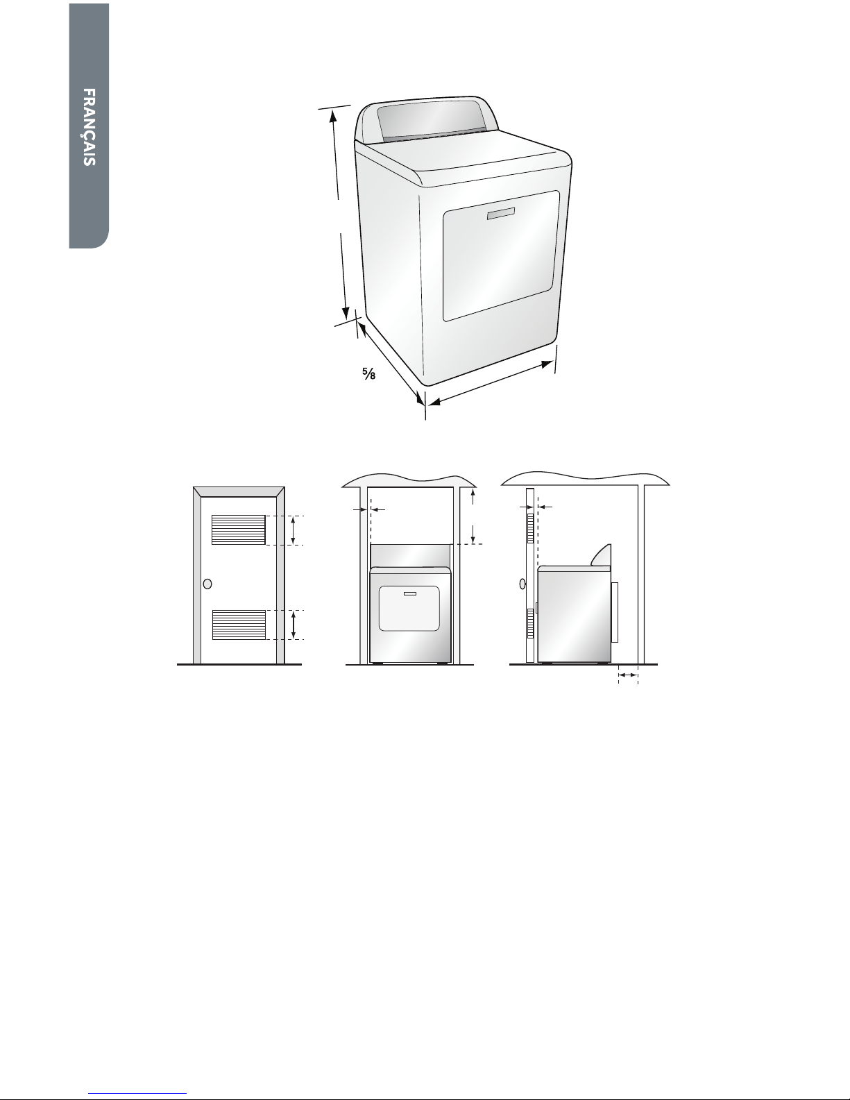
DIMENSIONS DE LA SÉCHEUSE
27"
(68,6 cm)
30
¼"
(77,7 cm)
42½"
(108,0 cm)
SPÉCIFICATIONS POUR ALCÔVE OU PLACARD
60 po
2
(387,1 cm2)
60 po
2
(387,1 cm2)
1"
(2,5 cm)
15"
(38,1 cm)
1"
(2,5 cm)
5½"
(14 cm)
DÉGAGEMENTS MINIMUMS
• Les dimensions indiquées correspondent aux dégagements minimaux
nécessaires.
• Il faut laisser un dégagement de chaque côté de la sécheuse aÞ n d’éviter tout
transfert de bruit.
• Il faut laisser un dégagement à l’arrière de la sécheuse pour permettre le
passage du conduit d’évacuation.
AUTRES SPÉCIFICATIONS
• L’évacuation de cette sécheuse doit se faire à l’extérieur.
• Ne pas installer cette sécheuse dans un placard avec porte pleine.
• La porte du placard doit comporter des persiennes ou des ouvertures
d’aération, avec une surface d’ouverture minimale de 120 po2 (774,2 cm2),
également répartie entre le haut et le bas de la porte. La circulation de l’air ne
doit être entravée en aucune manière.
• Aucun autre appareil fonctionnant à base de combustible ne doit être installé
dans le même placard que la sécheuse à gaz.
Page 43

41
SPÉCIFICATIONS DE L’ALIMENTATION ÉLECTRIQUE ET
DE L’ALIMENTATION EN GAZ
SÉCHEUSE ÉLECTRIQUE (É.-U. UNIQUEMENT)
AVERTISSEMENT
La sécheuse doit être branchée à une prise électrique à 3 ou 4 fils,
correctement reliée à la terre et délivrant une tension monophasée CA
uniquement de 120/240 V (ou 120/208 V) à 60 Hz, reliée à un circuit
individuel protégé par un fusible temporisé ou un disjoncteur de 30 A. Ne
pas faire fonctionner une laveuse et une sécheuse sur un même circuit.
AVERTISSEMENT
Cet appareil doit être relié à la terre. En cas de court-circuit, la liaison à
la terre réduit le risque de choc électrique, en permettant au courant de
s’échapper directement vers la terre.
REMARQUE : L’alimentation électrique de la sécheuse doit être conforme aux codes
et règlements locaux et à la version la plus récente du Code national de l’électricité,
ANSI/NFPA 70.
• Si l’alimentation électrique disponible à l’emplacement d’installation prévu pour
la sécheuse ne répond pas aux critères ci-dessus, contacter un électricien agréé.
• Les temps de séchage d’une sécheuse fonctionnant sur un circuit d’alimentation
de 208 V seront plus longs que ceux d’une sécheuse fonctionnant sur un circuit
de 240 V.
• La sécheuse n’est pas équipée de cordon d’alimentation électrique. Il est
nécessaire d’acheter séparément une trousse de cordon d’alimentation
conforme aux codes locaux régissant les installations électriques. La sécheuse
doit utiliser un cordon d’alimentation électrique à 3 ou 4 conducteurs NEMA
14- 30 ou 10-30 de type SRDT ou ST (comme nécessaire) de 120/240 VCA
minimum et 30 A, terminé par 3 cosses rondes ou en fourche à pointes relevées
et approuvé pour utilisation avec les sécheuses à linge.
• Un serre-câble homologué UL doit être Þ xé à la sécheuse pour maintenir le
cordon d’alimentation électrique.
• Ne pas utiliser de prise secteur à conducteurs en aluminium avec un cordon et
une Þ che d’alimentation électrique à conducteurs en cuivre (ou inversement).
Le raccordement correct comprend un cordon d’alimentation électrique à
conducteurs en cuivre et une prise secteur à conducteurs en cuivre.
• La prise électrique doit être située de façon à ce que le cordon d’alimentation
électrique soit accessible une fois la sécheuse installée.
Page 44

42
SÉCHEUSE ÉLECTRIQUE (CANADA UNIQUEMENT)
AVERTISSEMENT
La sécheuse doit être branchée à une prise électrique à 4 fils,
correctement reliée à la terre et délivrant une tension monophasée CA
uniquement de 120/240 V à 60 Hz, reliée à un circuit individuel protégé
par un fusible temporisé ou un disjoncteur de 30 A. Ne pas faire
fonctionner une laveuse et une sécheuse sur un même circuit.
AVERTISSEMENT
Cet appareil doit être relié à la terre. En cas de court-circuit, la liaison à
la terre réduit le risque de choc électrique, en permettant au courant de
s’échapper directement vers la terre.
REMARQUE : L’alimentation électrique de la sécheuse doit être conforme aux
codes et règlements locaux et à la dernière édition de la norme CSA C22.1 du Code
canadien de l’électricité, première partie.
• Si l’alimentation électrique disponible à l’emplacement d’installation prévu pour
la sécheuse ne répond pas aux critères ci-dessus, contacter un électricien agréé.
• Ne pas utiliser de prise secteur à conducteurs en aluminium avec un cordon et
une Þ che d’alimentation électrique à conducteurs en cuivre (ou inversement).
Le raccordement correct comprend un cordon d’alimentation électrique à
conducteurs en cuivre et une prise secteur à conducteurs en cuivre.
• La prise électrique doit être située de façon à ce que le cordon d’alimentation
électrique soit accessible une fois la sécheuse installée.
SÉCHEUSE À GAZ
SPÉCIFICATIONS DE L’ALIMENTATION ÉLECTRIQUE
AVERTISSEMENT
La sécheuse à gaz doit être branchée à une prise électrique à 3 fils,
correctement reliée à la terre, délivrant une tension monophasée CA
uniquement de 120 V à 60 Hz et protégée par fusible temporisé ou un
disjoncteur de 15 A.
AVERTISSEMENT
Cet appareil doit être relié à la terre. En cas de court-circuit, la liaison à
la terre réduit le risque de choc électrique, en permettant au courant de
s’échapper directement vers la terre.
Page 45
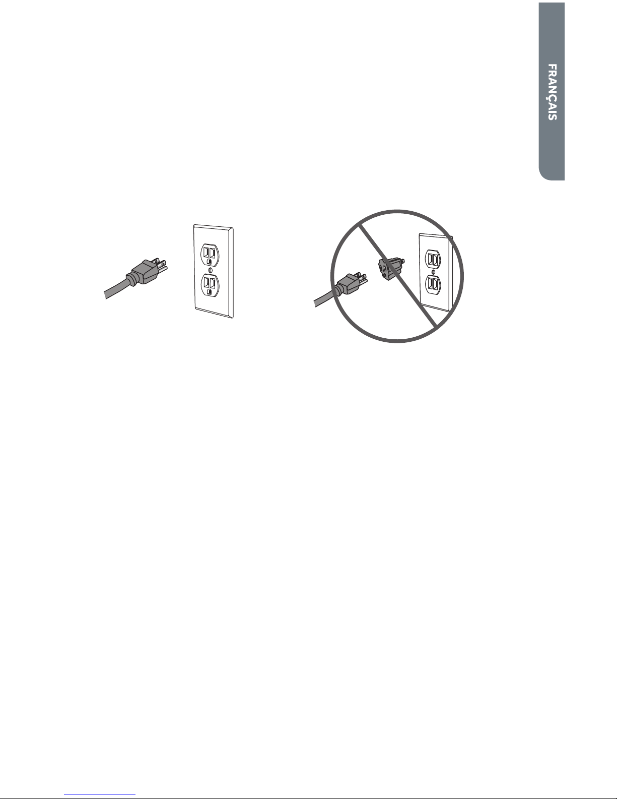
43
• Cette sécheuse comporte un cordon d’alimentation électrique à 3 broches. Ne
pas couper ou ôter la broche de terre du cordon d’alimentation électrique.
• Le cordon d’alimentation électrique doit être branché sur une prise de courant
de conÞ guration correspondante, à 3 broches, reliée à la terre et installée
conformément aux codes et règlements locaux. En l’absence de prise de courant
de conÞ guration correspondante, contacter un électricien agréé pour installer
une prise adaptée.
• En cas de doute sur la qualité de la liaison à la terre de la prise, consulter un
électricien agréé.
• Ne pas utiliser d’adaptateur à trois broches.
• Ne pas utiliser de rallonge.
SPÉCIFICATIONS DE L’ALIMENTATION EN GAZ
REMARQUE : L’alimentation en gaz de la sécheuse doit être conforme aux codes et
règlements locaux et à la dernière édition de la norme ANSI Z223.1 du National Fuel
Gas Code ou CAN/CGA B149.1 au Canada.
Gaz naturel
• La sécheuse est équipée pour une alimentation au gaz naturel.
Gaz propane
• La sécheuse peut être convertie pour une alimentation au gaz propane.
• L’opération de conversion au gaz propane doit être exécutée par un technicien
qualiÞ é.
Canalisation d’alimentation en gaz
• La canalisation d’alimentation en gaz doit avoir un diamètre de ½” (1,3 cm) et
comporter un robinet d’arrêt individuel manuel installé à 6 pi (183 cm) maximum
de la sécheuse, conformément au National Fuel Gas Code, ANSI Z223.1/NFPA
54 ou au Canada, au Code des installations pour gaz naturel ou propane, B149.1
pour le Canada.
• Le robinet d’arrêt doit être facilement accessible pour l’ouverture et la
fermeture.
• Un connecteur obturé (Þ letage NPT de " ou plus) accessible pour le
raccordement de l’instrument de mesure doit être installé immédiatement en
amont du raccord d’alimentation en gaz de la sécheuse.
• La canalisation d’alimentation doit se terminer par un raccord conique NPT de
!".
Page 46

44
Canalisation d’alimentation en gaz
NPT de ½"
Robinet d’arrêt du gaz
Connecteur obturé (Þ letage NPT de
" ou plus)
Raccord conique NPT !"
B
C
D
A
SPÉCIFICATIONS DU RACCORDEMENT DE
L’ALIMENTATION EN GAZ
Cette sécheuse doit être raccordée à la canalisation d’alimentation en gaz à l’aide
d’un connecteur de gaz ß exible homologué qui respecte les normes applicables aux
connecteurs utilisés avec des appareils ménagers à gaz, ANSI Z21.24 ou CSA 6.10.
Raccord à gaz en acier inoxydable ß exible :
• Si les codes locaux le permettent, utiliser un raccord neuf en acier inoxydable
ß exible (conception homologuée par l’American Gas Association ou par CSA
International) pour raccorder la sécheuse à la canalisation rigide d’alimentation
en gaz. Selon le besoin, utiliser un coude et un adaptateur de !" x tuyau NPT de
!" entre le raccord de gaz ß exible et la canalisation de gaz de la sécheuse, pour
éviter toute déformation.
SPÉCIFICATIONS DE L’ALIMENTATION DU BRÛLEUR
Altitudes inférieures ou égales à 10 000 pi (3 048 m) :
• La conception de cette sécheuse a été homologuée par CSA International
pour une utilisation jusqu’à une altitude de 10 000 pieds (3 048 m) pour le débit
thermique indiqué sur la plaque signalétique du numéro de modèle et de série.
Aucun réglage du brûleur n’est nécessaire lorsque la sécheuse est utilisée à une
altitude inférieure à cette valeur maximale.
Altitudes supérieures à 10 000 pieds (3 048 m) :
• Si la sécheuse doit être utilisée à une altitude supérieure à 10 000 pieds
(3 048 m), il faut réduire de 4 % le débit thermique du brûleur indiqué sur la
plaque signalétique du numéro de modèle et de série pour chaque tranche de
1 000 pieds (305 m) d’augmentation de l’altitude.
Test de pression de la canalisation de gaz :
• La sécheuse doit être déconnectée du système de canalisations d’alimentation
en gaz lors de tout test de pression à des pressions supérieures à ½ lb/po²
(3,5 kPa).
Page 47

45
SPÉCIFICATIONS DU SYSTÈME D’ÉVACUATION
AVERTISSEMENT
Cette section décrit les critères à respecter pour assurer la sécurité et
l’efficacité du système d’évacuation. Le non-respect de ces
instructions peut entraîner une mauvaise performance de la sécheuse,
un dommage à l’appareil ou un risque d’incendie.
IMPORTANT : L’évacuation de la sécheuse doit se faire à l’extérieur.
• L’évacuation de la sécheuse ne doit pas se faire dans un conduit d’évacuation de
gaz, une cheminée, un mur, un plafond ou un vide de construction.
CONDUITS
• Si le système d’évacuation existant est composé de conduits ß exibles en
plastique ou en papier métallisé, les remplacer par des conduits métalliques
rigides.
• Utiliser uniquement des conduits métalliques rigides de 4" (10,2 cm) de
diamètre.
• Pour réaliser des changements de direction avec les conduits, utiliser des
coudes à 45° plutôt qu’à 90°. Cela améliore la circulation de l’air et peut réduire
l’accumulation de charpie dans le système d’évacuation.
90° - Acceptable 45° - Idéal
• Ne pas dépasser la longueur de conduits par rapport au nombre de coudes
indiqué dans le tableau ci-dessous. Cela pourrait entraîner une accumulation de
charpie, augmenter la durée de séchage et créer un risque d’incendie.
• Deux coudes à 45° produisent le même freinage qu’un coude à 90°.
Page 48

46
Longueur maximale recommandée
du système d’évacuation
Types de bouches d’évacuation
Recommandé Utiliser uniquement pour
les circuits courts
4"
(10,2 cm)
4"
(10,2 cm)
de diamètre
4"
(10,2 cm)
de diamètre
2½"
(6,4 cm)
4"
(10,2 cm)
de
diamètre
Nombre de coudes à 90° Métallique rigide Métallique rigide
0
1
2
3
90 pieds
60 pieds
45 pieds
35 pieds
60 pieds
45 pieds
35 pieds
25 pieds
• Toutes les jointures doivent être étanches aÞ n d’éviter toute fuite d’air.
L’extrémité mâle de chaque section de conduit doit être orientée dans la
direction opposée à la sécheuse.
• Utiliser des brides ou du ruban adhésif pour conduit
pour sceller toutes les jointures. Ne pas utiliser de vis
ou autres dispositifs de Þ xation qui se prolongeraient à
l’intérieur du conduit pour sécuriser la jointure car cela
peut retenir la charpie.
Bride
• Éviter d’acheminer le système dans une zone non chau" ée car cela entraînera
la formation de condensation à l’intérieur du conduit et accélérera le rythme
d’accumulation de la charpie.
• Éviter de faire passer le circuit d’évacuation verticalement par un toit pour éviter
tout risque de courants d’air descendants susceptibles d’entraver la circulation
d’air.
• Éviter que le système d’évacuation ne s’a" aisse, ne soit compressé ou coincé
car cela réduira la circulation de l’air et a" ectera la performance de la sécheuse.
• Ne pas grillager l’extrémité du circuit d’évacuation. En s’accumulant, la charpie
Þ nira par obstruer le grillage. Utiliser une bouche d’évacuation homologuée à
l’extrémité du conduit à l’extérieur.
Page 49

47
BOUCHE D’ÉVACUATION
• Utiliser une bouche d’évacuation homologuée à clapet oscillant qui s’ouvre
lorsque la sécheuse est en fonctionnement. Lorsque la sécheuse s’arrête, le
clapet se ferme automatiquement pour éviter les courants d’air et l’entrée de
rongeurs et d’insectes.
• Les clapets à persiennes ou de type boîte sont recommandés. Les clapets
inclinés peuvent être utilisés, mais uniquement pour des circuits courts. Voir le
tableau “Longueur maximale recommandée du système d’évacuation” pour plus
d’information.
• AÞ n d’éviter de réduire la circulation de l’air, maintenir un dégagement minimal
de 12" (30,5 cm) entre le clapet d’évacuation et le plancher ou tout autre
obstacle éventuel.
RÉSIDENCE MOBILE – SPÉCIFICATIONS
SUPPLÉMENTAIRES
• L’installation doit satisfaire les critères de la version en cours de validité du
Manufactured Home Construction and Safety Standard, Titre 24 CFR, partie
3280 ou de la Norme canadienne des habitations préfabriquées, CAN/CSA-Z240
MH.
• Des dispositions particulières doivent être prises pour la circulation de l’air
d’appoint extérieur. L’ouverture d’entrée d’air doit être au moins deux fois plus
grande que la sortie d’évacuation de la sécheuse.
• Si l’évacuation d’air de la sécheuse se fait par le plancher dans un espace conÞ né
sous la résidence mobile, le circuit d’évacuation doit se terminer à l’extérieur de
cet espace et la sortie du conduit doit être solidement Þ xée à la structure de la
résidence mobile.
SÉCHEUSE À GAZ UNIQUEMENT
(RÉSIDENCE MOBILE UNIQUEMENT)
• La sécheuse doit être Þ xée au plancher à l’aide d’une trousse d’installation pour
résidence mobile. Suivre les instructions fournies avec la trousse.
Page 50

48
INSTRUCTIONS ÉTAPE PAR ÉTAPE
INSTALLATION DE LA SÉCHEUSE
Nous recommandons que l’installation de votre nouvelle sécheuse soit réalisée
par un technicien en électroménager qualiÞ é. Si on pense être capable d’installer
la sécheuse, lire soigneusement les instructions d’installation avant de procéder à
l’installation.
MISE EN GARDE : Si l’utilisateur n’est pas certain que la sécheuse soit
correctement installée après avoir suivi ces étapes, contacter un technicien en
électroménager qualiÞ é.
ÉTAPE 1 – DÉBALLAGE DE LA SÉCHEUSE
1. Enlever tous les matériaux d’emballage. Cela comprend la base en polystyrène
et tous les adhésifs maintenant les accessoires de la sécheuse en place, à la fois
à l’intérieur et à l’extérieur.
2. Inspecter la sécheuse et retirer tout emballage, ruban adhésif ou document
resté sur l’appareil avant de l’utiliser.
AVERTISSEMENT
Afin d’éviter tout risque d’étouffement, conserver le sac en plastique et
autres matériaux d’emballage hors de portée des bébés et des enfants.
Ne pas utiliser ce sac dans des berceaux, poussettes ou parcs pour
enfants. Le sac en plastique peut bloquer les orifices du nez et de la
bouche et empêcher la respiration. Ce sac n’est pas un jouet.
ÉTAPE 2 – POSE D’UN CORDON D’ALIMENTATION
ÉLECTRIQUE SUR LA SÉCHEUSE (SÉCHEUSE
ÉLECTRIQUE UNIQUEMENT)
1. Ôter la vis Þ xant le couvercle de l’ouverture d’accès du boîtier de connexion,
situé dans le coin supérieur gauche de l’arrière de la sécheuse.
Couvercle de l’ouverture d’accès
du boîtier de connexion
Trou dans le support de montage
pour serre-câble
Vis du couvercle de l’ouverture
d’accès
A
B
C
Page 51

49
2. Insérer un serre-câble homologué UL dans le trou du support de montage.
Positionner le serre-câble de façon à ce qu’un onglet soit orienté vers le haut
et l’autre vers le bas. Serrer les vis du serre-câble juste assez pour maintenir
ensemble les deux moitiés.
Onglet
Serre-câble
A
B
3. Insérer un cordon d’alimentation électrique dans le serre-câble. VériÞ er que la
gaine d’isolement du cordon d’alimentation électrique se glisse à l’intérieur du
serre-câble.
4. Pour le raccordement d’un cordon d’alimentation électrique
à 4 conducteurs, suivre les instructions de la partie A. Pour le
raccordement d’un cordon d’alimentation à 3 conducteurs, suivre les
instructions de la partie B.
4 Þ ls (recommandé) si votre domicile est équipé d’une prise secteur à
4 conducteurs (NEMA 14-30 type SRDT ou ST) :
3 Þ ls (en l’absence de circuit 4 Þ ls) si votre domicile est équipé d’une
prise secteur à 3 conducteurs (NEMA 10-30 type SRDT) :
MISE EN GARDE : Un raccordement à 4 Þ ls est obligatoire pour les
résidences mobiles et lorsque les codes locaux n’autorisent pas
l’utilisation de raccordements à 3 Þ ls.
5. Serrer les vis du serre-câble.
6. Veiller à ce qu’aucun conducteur ne touche le tambour à l’intérieur de la caisse
de la sécheuse.
7. Réinstaller le couvercle du boîtier de connexion.
Page 52

50
PARTIE A – CORDON D’ALIMENTATION ÉLECTRIQUE À
4 CONDUCTEURS
A
B
C
F
E
G
D
Vis de liaison à la terre (verte)
Vis du boîtier de connexion
Conducteur de liaison du neutre à la
terre (vert)
Conducteur de liaison à la terre du
cordon d’alimentation électrique
(vert)
Conducteur neutre du cordon
d’alimentation électrique (blanc)
Conducteurs de ligne du cordon
d’alimentation électrique (un
rouge, un noir)
Cordon d’alimentation électrique
A1. Retirer la vis verte de liaison à la terre qui connecte le conducteur de liaison du
neutre à la terre (vert) à la caisse et la vis centrale du boîtier de connexion, puis
jeter le conducteur de liaison.
A2. Fixer le conducteur de liaison à la terre du cordon d’alimentation électrique (vert)
à la caisse de la sécheuse au moyen de la vis verte de liaison à la terre. Bien serrer
la vis.
A3. Fixer le conducteur neutre (blanc) du cordon d’alimentation électrique au moyen
de la vis centrale du boîtier de connexion. Bien serrer la vis.
A4. Fixer chacun des 2 conducteurs restants du cordon d’alimentation électrique
(rouge et noir) au moyen des vis les plus à l’extérieur du boîtier de connexion.
Fixer un conducteur à chaque boîtier de connexion comme montré sur le
schéma. Bien serrer les deux vis.
IMPORTANT : Ne pas plier excessivement les conducteurs et ne pas les sertir
aux connexions.
Page 53

51
PARTIE B – CORDON D’ALIMENTATION 3 FILS
A
B
C
E
D
F
Vis de liaison à la terre (verte)
Vis du boîtier de connexion
Conducteur de liaison du neutre à la
terre (vert)
Conducteur neutre du cordon
d’alimentation électrique (blanc)
Conducteurs de ligne du cordon
d’alimentation électrique (un
rouge, un noir)
Cordon d’alimentation électrique
B1. Fixer le conducteur neutre (blanc) du cordon d’alimentation électrique à la vis
centrale du boîtier de connexion. Bien serrer la vis.
B2. Fixer chacun des 2 conducteurs restants du cordon d’alimentation électrique
(rouge et noir) au moyen des vis les plus à l’extérieur du boîtier de connexion.
Fixer un conducteur à chaque boîtier de connexion comme montré sur le
schéma. Bien serrer les deux vis.
IMPORTANT : Ne pas plier excessivement les conducteurs et ne pas les sertir
aux connexions.
ÉTAPE 2 – RACCORDEMENT À UNE CANALISATION
D’ALIMENTATION EN GAZ
(SÉCHEUSE À GAZ UNIQUEMENT)
REMARQUE : Ne pas raccorder la sécheuse à une canalisation de gaz propane sans
convertir d’abord la sécheuse à l’aide d’une trousse de conversion. Une trousse de
conversion au gaz propane doit être installée par un technicien qualiÞ é.
REMARQUE : Appliquer un composé d’étanchéité des tuyauteries résistant à
l’action du gaz propane sur tous les Þ letages mâles. Ne pas utiliser de ruban adhésif
pour tuyauterie.
1. Fermer l’alimentation en gaz en plaçant le robinet d’arrêt en position fermée.
Robinet fermé
Robinet ouvert
A
B
2. Déconnecter et jeter l’ancien connecteur de gaz ß exible. Remplacer l’ancien
connecteur par un connecteur de gaz ß exible neuf homologué CSA (AGA).
Page 54

52
3. Retirer le capuchon d’expédition de la canalisation d’arrivée de gaz situé à
l’arrière de la sécheuse.
4. Raccorder un coude NPT !" à la canalisation d’arrivée de gaz sur la sécheuse.
Raccorder ensuite un adaptateur conique au coude.
IMPORTANT : Utiliser une clé à tuyauterie pour empêcher la canalisation
d’arrivée de gaz de la sécheuse de se tordre.
Canalisation d’arrivée
de gaz sur la sécheuse
Coude NPT de !"
Adaptateur conique
NPT de !"
A
B
C
5. Raccorder la sécheuse à la canalisation d’alimentation en gaz avec un
connecteur de gaz ß exible.
Connecteur de gaz
ß exible
A
6. Serrer le connecteur de gaz ß exible à l’aide de deux clés à molette.
7. Ouvrir l’alimentation en gaz en plaçant le robinet d’arrêt en position ouverte. Le
robinet est ouvert lorsque la poignée est parallèle au conduit d’alimentation en
gaz.
8. VériÞ er qu’aucun raccordement ne présente de fuite en les badigeonnant d’une
solution de détection des fuites non corrosive. L’apparition de bulles indique
la présence d’une fuite. Si une fuite est détectée, fermer le robinet d’arrêt,
resserrer la jointure, ouvrir le robinet d’arrêt puis contrôler à nouveau les
raccordements.
AVERTISSEMENT
Ne jamais effectuer de test de détection de fuite de gaz avec une
flamme nue.
Page 55

53
ÉTAPE 3 - RACCORDEMENT À UN SYSTÈME
D’ÉVACUATION
AVERTISSEMENT
Pour réduire le risque d’incendie, cette sécheuse doit évacuer l’air à
l’extérieur.
1. VériÞ er que le système d’évacuation n’est pas obstrué par une accumulation de
charpie avant de raccorder la sécheuse.
2. Utiliser des conduits métalliques rigides ou ß exibles de 4’’ (102 mm) pour
raccorder la sortie d’évacuation de la sécheuse au système d’évacuation.
3. Utiliser des brides pour sceller toutes les jointures. Les conduits d’évacuation ne
doivent pas être connectés avec des vis ou tout autre dispositif de serrage qui
se prolonge à l’intérieur du conduit.
REMARQUES :
• Ne pas utiliser de conduit en papier métallisé ou en plastique ß exible. Cela
pourrait entraîner une accumulation de charpie à l’intérieur des conduits,
réduire la circulation de l’air et créer un risque d’incendie. Une circulation de l’air
restreinte augmentera les durées de séchage.
• L’évacuation de la sécheuse ne doit pas se faire dans un conduit d’évacuation de
gaz, une cheminée, un mur, un plafond ou un vide de construction. L’évacuation
de la sécheuse doit se faire à l’extérieur. Si l’on ne raccorde pas l’évacuation de
la sécheuse à l’extérieur, de la charpie Þ ne sera évacuée dans la buanderie. Une
accumulation de charpie dans le domicile peut représenter un risque sanitaire et
un risque d’incendie.
Page 56

54
ÉTAPE 4 – NIVELLEMENT DE LA SÉCHEUSE
1. Installer la sécheuse à son emplacement Þ nal. Veiller à ne pas écraser ni
déformer le conduit d’évacuation. VériÞ er que les quatre pieds sont en contact
ferme avec le plancher et que la sécheuse repose solidement dessus.
REMARQUE : Pour une sécheuse à gaz, vériÞ er que la canalisation de gaz ß exible
n’est pas déformée.
2. À l’aide d’un niveau, vériÞ er que la sécheuse est d’aplomb transversalement et
d’avant en arrière.
3. Si la sécheuse n’est pas d’aplomb, ajuster les pieds de nivellement. Tourner
les pieds dans le sens horaire pour les déployer (et relever la sécheuse) ou
antihoraire pour les rétracter (et abaisser la sécheuse).
ÉTAPE 5 – FIN DE L’INSTALLATION
1. Brancher le cordon d’alimentation électrique de la sécheuse à une prise de
courant adéquate.
2. Restaurer l’alimentation électrique au niveau de la prise. VériÞ er que le
disjoncteur est activé.
3. Jeter/recycler tous les matériaux d’emballage.
4. S’assurer que l’espace autour de la sécheuse est propre et exempt de matériaux
combustibles, essence et autres vapeurs inß ammables. Veiller aussi à ce
qu’aucun élément (boîtes, vêtements, etc.) n’entrave la circulation d’air de
combustion et de ventilation par le panneau à persiennes situé à l’arrière de la
sécheuse.
5. Tester le fonctionnement de la sécheuse en sélectionnant un programme
minuté de séchage à l’air chaud. Voir la section “Instructions d’utilisation”.
REMARQUE : Pour les sécheuses à gaz, il est impératif de purger la canalisation
de gaz avant d’allumer le brûleur. Si le brûleur ne s’allume pas en 45 secondes
maximum lors de la première mise en marche de la sécheuse, l’interrupteur de
sécurité éteint le brûleur. Si cela se produit, éteindre la sécheuse et attendre 5
minutes avant de réessayer d’allumer le brûleur.
Page 57

55
TABLEAU DE COMMANDE ET
CARACTÉRISTIQUES
TABLEAU DE COMMANDE
H
I
G
H
-
L
O
W
-
O
F
F
Timed Dry Adjust
Cycle
Signal
Damp
Signal
More
Normal
Less
Medium
Low
Extra Low
No Heat
150 Min
60 Min
Cycle
Status
POWER
High
Heavy
Duty
Eco Dry
Perm
Press
Delicate
Sanitize
Air Dry
Touch Up
Quick
Dry
Timed Dry
NormalN
ormal
AUTOMATIC C YCLES
TIMED DRY CYCLES
Drying
Cool Down
Wrinkle Saver
Clean Lint
T
I
M
E
D
D
R
Y
O
N
L
A
U
T
O
C
Y
C
L
E
S
O
N
L
Y
o a
Normal
Dry
Dry
Temp
Wrinkle
Saver
Level
ESTIMATED TIME REMAINING
A
B
C
D
E
F
G
H
I
J
K
TÉMOINS LUMINEUX DE PROGRAMME
• Lors de la mise sous tension initiale de la sécheuse, les témoins lumineux de
programme indiquent les étapes du programme sélectionné.
• Pendant que la sécheuse fonctionne, l’étape en cours clignote. Une fois une
étape terminée, le témoin s’éteint et celui de l’étape suivante commence à
clignoter.
• Le programme de séchage est entièrement terminé lorsque tous les
témoins lumineux s’éteignent.
• Le témoin lumineux Check Lint Screen (contrôle du Þ ltre à charpie) s’allume
lorsque la sécheuse est mise en marche pour rappeler à l’utilisateur de
nettoyer le Þ ltre à charpie. Il s’éteint quand un programme de séchage
commence.
BOUTON POWER (MISE SOUS TENSION)
• Utiliser ce bouton pour mettre la sécheuse sous tension et hors tension.
REMARQUE : Si la sécheuse est sous tension et qu’aucun programme n’est
lancé, elle s’éteint automatiquement au bout de 5 minutes.
BOUTON DRY LEVEL (NIVEAU DE SÉCHAGE)
• Utiliser ce bouton pour ajuster le niveau de séchage des programmes
automatiques.
REMARQUE : Ce bouton fonctionne uniquement avec les programmes
automatiques.
Page 58

56
BOUTON DE SÉLECTION DU PROGRAMME
• Il est possible de choisir parmi 6 programmes automatiques :
Sanitize (assainissement) - Utiliser ce programme pour assainir des pièces
comme les serviettes, les articles de literie et les vêtements d’enfant. Il est
recommandé de ne pas interrompre ce programme.
Heavy Duty (service intense) - Utiliser ce programme pour sécher à haute
température des tissus épais, comme les serviettes et les jeans.
Normal - Utiliser ce programme pour sécher à température moyenne les
articles en coton et le linge de maison.
Eco Dry (séchage écologique) - Utiliser ce programme pour réaliser des
économies d’énergie. Ce programme est semblable au programme Normal,
mais fonctionne à une température légèrement inférieure et obtient un
niveau de séchage légèrement plus faible.
Perm Press (pressage permanent) - Utiliser ce programme pour sécher les
tissus infroissables et à séchage à basse température
Delicate (articles délicats) - Utiliser ce programme pour sécher en douceur à
très basse température les articles délicats.
• Il est possible de choisir parmi 4 programmes Timed Dry (séchage minuté) :
Timed Dry (séchage minuté) - Utiliser ce programme pour faire fonctionner
la sécheuse pendant la durée réglée. Les vêtements peuvent être humides
ou séchés excessivement à la Þ n du programme.
Quick Dry (séchage rapide) - Utiliser ce programme pour choisir facilement
un programme de 20 minutes, aÞ n de sécher rapidement quelques articles.
Touch Up (rafraîchissement) - Utiliser ce programme pour choisir facilement
un programme de 10 minutes, aÞ n de rafraîchir des vêtements propres.
Air Dry (séchage à l’air) - Utiliser ce programme pour sécher la mousse, le
caoutchouc, le plastique ou les tissus sensibles à la chaleur.
BOUTON START/PAUSE (MISE EN MARCHE/PAUSE)
• Appuyer sur ce bouton pour démarrer un programme sélectionné ou
suspendre un programme en cours.
REMARQUE : Une fois un programme lancé, on doit le suspendre pour
modiÞ er une des options.
REMARQUE : Si l’on ouvre la porte de la sécheuse, le programme en cours
sera également suspendu.
REMARQUE : Lorsque le statut du programme est sur Wrinkle Saver
(antifroissement), si l’on appuie sur le bouton Pause ou que l’on ouvre la
porte de la sécheuse, le programme en cours sera annulé et l’alimentation
électrique sera coupée.
BOUTON DRY TEMP (TEMPÉRATURE DE SÉCHAGE)
• Utiliser ce bouton pour sélectionner une température de séchage. Pour des
résultats optimaux, suivre les instructions sur l’étiquette des vêtements
et utiliser la température de séchage la plus élevée possible qui reste sans
danger pour le tissu.
REMARQUE : Ce bouton fonctionne uniquement avec les programmes à
séchage minuté. La fonction No Heat (sans chaleur) n’est pas disponible
avec un programme automatique.
Page 59

57
BOUTON WRINKLE SAVER (ANTI-FROISSEMENT)
• À la Þ n du programme de refroidissement, la sécheuse fait culbuter la charge
périodiquement pendant 1 heure aÞ n d’empêcher que les vêtements ne
se froissent. Utiliser ce bouton pour prolonger cette fonction pendant 150
minutes ou pour la désactiver.
AFFICHAGE ESTIMATED TIME REMAINING
(DURÉE RESTANTE ESTIMÉE)
• Cet a# chage montre le temps total estimé pour un programme de séchage
en minutes. Pendant que la sécheuse fonctionne, le décompte du temps
restant s’a# che.
• Si la sécheuse détecte un problème, un code d’erreur apparaîtra sur cet
a# chage. Veuillez consulter la section “Dépannage” pour une liste des
codes d’erreur et des causes et solutions possibles.
BOUTONS TIMED DRY AJUST
(AJUSTEMENT DU SÉCHAGE MINUTÉ)
• Utiliser ces boutons pour ajuster la longueur d’un programme de séchage
minuté. La durée peut être ajustée de 10 à 95 minutes, par tranches de
5 minutes.
REMARQUE : Lorsque le statut du programme est sur Cool Down
(refroidissement), la durée ne peut pas être ajustée.
CYCLE SIGNAL BUTTON (SIGNAL DE PROGRAMME)
• Utiliser ce bouton pour ajuster le volume des signaux sonores du tableau de
commande et de Þ n de programme.
BOUTON DAMP SIGNAL (SIGNAL D’HUMIDITÉ)
• Utiliser ce bouton pour activer ou désactiver le signal d’humidité. La
fonction de signal d’humidité avertit l’utilisateur quand les vêtements
sont secs à environ 80 %. Elle s’avère utile quand on souhaite retirer des
articles partiellement secs que l’on a l’intention de repasser. Cela donne
aussi la possibilité de démêler et de redistribuer les articles volumineux ou
encombrants avant la Þ n du programme.
REMARQUE : Si le signal de programme est désactivé, le signal d’humidité
reste actif.
Page 60
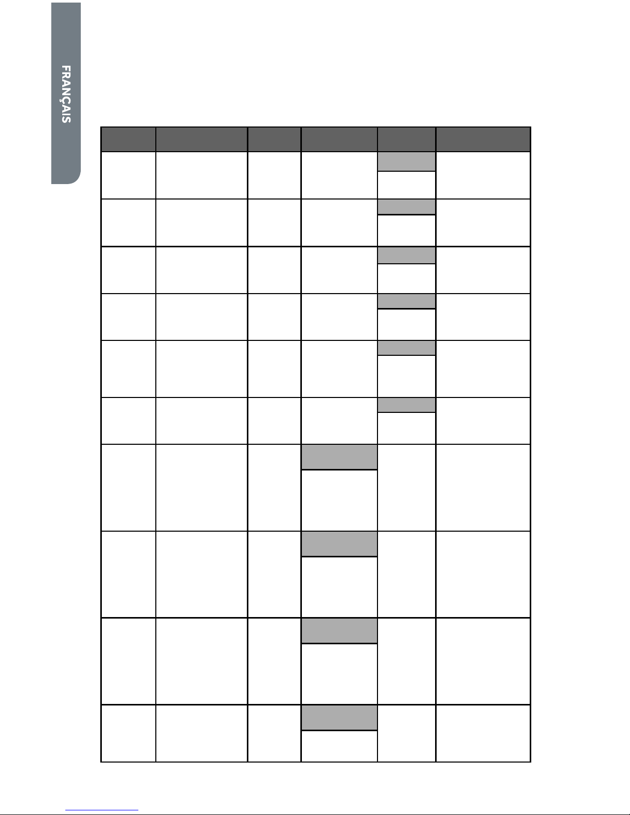
58
GUIDE DES PROGRAMMES
REMARQUE : Pour la protection de vos vêtements, tous les réglages et options
ne sont pas disponibles sur tous les programmes. Les cases grisées indiquent les
réglages par défaut correspondant à chaque programme.
PRO-
GRAMME
TYPE DE TISSU
DURÉE
ESTIMÉE
TEMPÉRATURE
DE SÉCHAGE
NIVEAU DE
SÉCHAGE
OPTIONS
Sanitize
(assaini-
ssement)
Serviettes,
articles de literie,
vêtements
d’enfants
70
High (Élevée)
More (Plus)
Wrinkle Saver
(anti-froissement)
Damp Signal
(signal d’humidité)
Heavy
Duty
(service
intense)
Articles lourds tels
que serviettes et
jeans
45
High (Élevée)
Normal
Wrinkle Saver
(anti-froissement)
Damp Signal
(signal d’humidité)
More (Plus)
Less (Moins)
Normal
Articles en coton,
linge de maison et
charges mixtes
42
Medium
(Moyenne)
Normal
Wrinkle Saver
(anti-froissement)
Damp Signal
(signal d’humidité)
More (Plus)
Less (Moins)
Eco Dry
(séchage
écologique)
Articles en coton,
linge de maison et
charges mixtes
40
Medium
(Moyenne)
Normal
Wrinkle Saver
(anti-froissement)
Damp Signal
(signal d’humidité)
More (Plus)
Less (Moins)
Perm
Press
(pressage
perm-
anent)
Mélanges coton/
polyester, chemises
et pantalons
infroissables
35
Low (Basse)
Normal
Wrinkle Saver
(anti-froissement)
Damp Signal
(signal d’humidité)
More (Plus)
Less (Moins)
Delicate
(articles
délicats)
Lingerie,
chemisiers et tissus
synthétiques
28
Extra Low
(Très basse)
Normal Wrinkle Saver
(anti-froissement)
Damp Signal
(signal d’humidité)
More (Plus)
Less (Moins)
Timed Dry
(séchage
minuté)
Articles en coton,
linge de maison et
charges mixtes
40
Réglable
(10-95)
Medium
(Moyenne)
N/A
Wrinkle Saver
(anti-froissement)
High (Élevée)
Low (Basse)
Extra Low
(Très basse)
No Heat
(Sans chaleur)
Quick Dry
(séchage
rapide)
Petites charges et
articles de sport
20
Réglable
(10 to 95)
Medium
(Moyenne)
N/A N/A
High (Élevée)
Low (Basse)
Extra Low
(Très basse)
No Heat
(Sans chaleur)
Touch Up
(rafraîchi-
ssement)
Articles en coton,
linge de maison et
charges mixtes
10
Réglable
(10 to 95)
Medium
(Moyenne)
N/A N/A
High (Élevée)
Low (Basse)
Extra Low
(Très basse)
No Heat
(Sans chaleur)
Air Dry
(séchage à
l’air)
Caoutchouc,
plastique et tissus
sensibles à la
chaleur
40
Réglable
(10 to 95)
No Heat
(Sans chaleur)
N/A N/A
Page 61
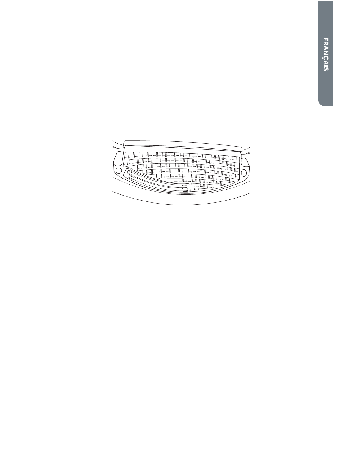
59
CARACTÉRISTIQUES
CAPTEUR DU NIVEAU D’HUMIDITÉ
• Le capteur du niveau d’humidité permet à la sécheuse de détecter le taux
d’humidité des vêtements de la charge. Les programmes automatiques utilisent
cette information, ainsi que des mesures de température de l’air pour terminer
le programme de séchage en temps voulu. Cette technologie intelligente
permet d’économiser de l’énergie, réduit le taux d’électricité statique et
protège les vêtements des dommages liés à un séchage excessif.
• Le capteur fournit également des résultats de séchage cohérents et précis et
permet à l’utilisateur de régler les performances de la sécheuse avec précision
au moyen du bouton Dry Level (niveau de séchage).
LAMPE INTERNE DU TAMBOUR
• La lampe interne du tambour aide l’utilisateur à mieux voir à l’intérieur de la
sécheuse et à retrouver tous ses articles séchés. Un interrupteur sur la caisse
allume automatiquement la lumière quand la porte est ouverte et l’éteint quand
elle est fermée.
• Voir le Guide d’entretien et de nettoyage pour des instructions étape par étape
sur le remplacement de l’ampoule.
Page 62

60
INSTRUCTIONS D’UTILISATION
ÉTAPE 1 – PRÉPARATION ET TRI DU LINGE
• Consulter les étiquettes des vêtements pour les instructions de séchage du
fabricant.
• Si possible, retourner les poches pour obtenir un séchage uniforme.
• Attacher les ceintures et les cordons pour qu’ils ne s’emmêlent pas.
• Fermer les fermetures à glissière, les boutons pression et les crochets aÞ n qu’ils
ne s’accrochent pas.
• S’assurer que les boutons et ornements des vêtements résistent à des
températures élevées et qu’ils n’endommageront pas la surface du tambour.
• AÞ n d’éviter que les taches ou souillures ne se Þ xent sur les tissus, vériÞ er que
toutes les taches et souillures ont été éliminées durant le programme de lavage.
Si ce n’est pas le cas, laver à nouveau les articles tachés.
• Pour éviter que les vêtements ne s’emmêlent et faciliter leur retrait de la
machine, placer les petits articles dans un Þ let à vêtements avant de charger le
linge.
• Séparer les tissus qui retiennent la charpie de ceux qui la forment. Les
vêtements susceptibles de produire de la charpie doivent être retournés sur
l’envers avant d’être placés dans la sécheuse.
ÉTAPE 2 - NETTOYAGE DU FILTRE À CHARPIE
1. Nettoyer le Þ ltre à charpie avant chaque utilisation. Pour retirer le Þ ltre à
charpie, tirer sur la poignée du Þ ltre à charpie située à l’intérieur de la porte de la
sécheuse.
2. Faire rouler la charpie accumulée sur le Þ ltre à charpie avec les doigts pour la
retirer. Ne pas rincer ni laver le Þ ltre pour enlever la charpie.
3. Réinstaller le Þ ltre à charpie en le faisant glisser.
REMARQUES :
• Ne pas utiliser la sécheuse si le Þ ltre à charpie n’est pas en place. Sans le Þ ltre,
les vêtements à sécher pourraient pénétrer dans le système d’évacuation et
endommager la sécheuse.
• L’accumulation de charpie sur le Þ ltre réduira la circulation de l’air et allongera la
durée de séchage.
Page 63

61
ÉTAPE 3 – CHARGEMENT DE LA SÉCHEUSE
1. Charger les vêtements humides dans le tambour de la sécheuse sans les tasser.
2. Fermer la porte de la sécheuse.
REMARQUES :
• Ne pas remplir la sécheuse de vêtements.
• Une charge de linge adéquate doit représenter entre un tiers et la moitié du
volume du tambour. Laisser su# samment d’espace dans l’appareil pour que
les vêtements puissent culbuter librement et sécher uniformément sans se
froisser.
• Pour sécher des articles volumineux, ne charger que 2 à 3 articles à la fois en les
mêlant à quelques vêtements de petite et moyenne taille.
• Pour les vêtements délicats et les petites charges, ajouter quelques serviettes
pour que les vêtements culbutent correctement. Cela permettra aux
vêtements de sécher de façon uniforme et sans se froisser.
ÉTAPE 4 – DÉMARRAGE DE LA SÉCHEUSE
1. Mettre la sécheuse sous tension en appuyant sur le BOUTON POWER (mise sous
tension).
2. Sélectionner un programme en faisant tourner le BOUTON DE SÉLECTION DU
PROGRAMME.
3. Si nécessaire, modiÞ er les réglages et les options par défaut.
4. Pour démarrer la sécheuse, appuyer sur le BOUTON START/PAUSE (mise en
marche/pause) à l’avant du bouton rotatif.
REMARQUE :
• Si l’on ouvre la porte, le programme en cours sera suspendu. Fermer la porte et
appuyer sur le BOUTON START/PAUSE (mise en marche/pause) pour reprendre
le programme.
Page 64

62
GUIDE D’ENTRETIEN ET DE NETTOYAGE
AVERTISSEMENT
Toujours débrancher la sécheuse avant le nettoyage afin d'éviter tout
choc électrique.
Le non-respect de cet avertissement peut entraîner un décès ou des
blessures.
Avant d’utiliser des produits de nettoyage, toujours lire et suivre les
instructions et avertissements du fabricant afin d’éviter toute blessure
ou tout dommage du produit.
NETTOYAGE ET ENTRETIEN
• Utiliser uniquement un chi" on humide ou imbibé d’eau savonneuse pour
nettoyer le tableau de commande.
• Si l’on renverse de l’assouplissant pour tissu, de l’agent de blanchiment ou du
détergent liquide/en poudre sur la caisse, essuyer immédiatement la caisse
pour éviter d’endommager le revêtement.
• Ne pas utiliser de nettoyants abrasifs, de produits chimiques puissants,
d’ammoniaque, d’agent de blanchiment au chlore, de détergent concentré ou
de solvants pour nettoyer la sécheuse. Ces produits chimiques peuvent se
dissoudre, endommager ou décolorer la sécheuse.
• Ne pas utiliser de nettoyant en atomiseur pour nettoyer l’intérieur de la
sécheuse. Cela pourrait produire des vapeurs dangereuses ou entraîner un choc
électrique. Si le tambour est taché, nettoyer avec un linge humide. Retirer tout
résidu éventuel avant de sécher la charge suivante.
NETTOYAGE DU FILTRE À CHARPIE
• Des résidus de détergent ou d’assouplissant pour tissu peuvent s’accumuler
sur le Þ ltre à charpie. Cette accumulation peut rallonger le temps de séchage
ou entraîner l’arrêt de la sécheuse avant que la charge ne soit complètement
sèche.
• Nettoyer le Þ ltre à charpie tous les 6 mois ou plus souvent s’il est obstrué par
une accumulation de résidus.
Étapes à suivre pour le nettoyage du Þ ltre à charpie :
1. Retirer la charpie accumulée en quantité normale avec les doigts.
2. Mouiller les deux côtés du Þ ltre à charpie avec de l’eau chaude.
3. Appliquer du détergent liquide mélangé à de l’eau et frotter à l’aide d’une brosse
en nylon.
4. Rincer soigneusement le Þ ltre à charpie à l’eau chaude.
5. Sécher complètement le Þ ltre à charpie avant de le réinstaller et d’utiliser à
nouveau la sécheuse.
Page 65

63
RETIRER LA CHARPIE ACCUMULÉE
À l’intérieur de la caisse de la sécheuse
• Retirer la charpie tous les 2 ans ou plus souvent, selon l’utilisation de la
sécheuse. Le nettoyage doit être e" ectué par une personne qualiÞ ée.
Système d’évacuation
• Le système d’évacuation doit être contrôlé et nettoyé tous les 12 mois au moins
dans des conditions d’utilisation normales. Plus on utilise la sécheuse, plus on
doit augmenter la fréquence d’inspection du système d’évacuation et de la
bouche d’évacuation de la sécheuse pour en vériÞ er le bon fonctionnement.
REMPLACER L’AMPOULE DE LA LAMPE INTERNE DU
TAMBOUR
L’ampoule de la lampe interne du tambour peut être remplacée par une ampoule de
15 W ou 30 W, de forme T7, à base intermédiaire (E17), de 120 V.
1. Déconnecter l’alimentation électrique ou débrancher la sécheuse.
2. Ouvrir la porte de la sécheuse. La lampe se trouve à l’intérieur du tambour,
au-dessus de l’ouverture de la porte.
3. À l’aide d’un tournevis Phillips, retirer la vis du couvercle transparent de la lampe.
Onglets du boîtier
Couvercle
transparent de la
lampe
Vis
C
A
B
4. Retirer le couvercle transparent de la lampe en le faisant tourner vers l’avant et
en le soulevant pour le sortir des onglets du boîtier.
5. Tourner l’ampoule dans le sens antihoraire pour la dévisser.
6. Remplacer l’ampoule par une ampoule de 15 W ou 30 W, de forme T7, à base
intermédiaire (E17), de 120 V.
7. Remettre en place le couvercle transparent de la lampe et le Þ xer à l’aide de la
vis.
8. Reconnecter la source de courant électrique ou rebrancher la sécheuse.
Page 66

64
PRÉCAUTIONS À PRENDRE AVANT UN DÉPART EN
VACANCES
• Débrancher la sécheuse de la prise de courant ou déconnecter l’alimentation
électrique.
• Nettoyer le Þ ltre à charpie. Voir la section “Nettoyage du Þ ltre à charpie”.
• (Pour les sécheuses à gaz uniquement) : Fermer le robinet d’arrêt de la
canalisation de gaz.
PRÉPARATION AVANT UN DÉMÉNAGEMENT OU UN
ENTREPOSAGE
Suivre les étapes suivantes en complément des étapes de la section “Précautions à
prendre avant un départ”.
• Déconnecter la sécheuse du système d’évacuation.
• Tourner les pieds de nivellement de façon à ce qu’ils soient complètement
rétractés dans la caisse de la sécheuse.
• Utiliser du ruban adhésif de masquage pour Þ xer la porte de la sécheuse.
• Déplacer et entreposer la sécheuse uniquement en position verticale.
REMARQUE : Pour les sécheuses à gaz, fermer l’arrivée de gaz qui alimente la
sécheuse. Déconnecter la sécheuse de la canalisation d’alimentation en gaz
et retirer les raccords Þ xés au tuyau d’arrivée de gaz de la sécheuse. Fermer la
canalisation d’alimentation en gaz à l’aide d’un bouchon.
Page 67

65
DÉPANNAGE
CODES D’ERREUR
Quand la sécheuse détecte une erreur, toutes les opérations s’arrêtent, une série
de 4 signaux sonores retentit et un code d’erreur apparaît sur l’a# chage Estimated
Time Remaining (durée résiduelle estimée).
CODE D’ERREUR DESCRIPTION CAUSE ET SOLUTIONS POSSIBLES
F3
(Court-circuit)
La sécheuse a détecté un
problème électrique qui nécessite
l’intervention d’un technicien
QualiÞ é pour une intervention de
dépannage.
F4
(Problème de l’élément
de chau" age)
La sécheuse électrique a détecté
un problème concernant l’élément
de chau" age qui nécessite
l’intervention d’un technicien
qualiÞ é.
QualiÞ é pour une intervention de
dépannage.
La sécheuse à gaz a détecté un
problème concernant le brûleur.
VériÞ er que le robinet d’arrêt de
la canalisation de gaz est bien
ouvert.
Si le robinet est ouvert, contacter
le service de dépannage.
E6
(Problème de
circulation de l’air)
La sécheuse a détecté que l’air ne
circule pas.
VériÞ er que le Þ ltre à charpie
est propre. Contrôler que votre
système d’évacuation n’a pas
d’obstructions manifestes. Si
l’erreur persiste, appeler pour
demander une intervention de
dépannage.
BRUITS DE FONCTIONNEMENT NORMAUX
• Les bruits suivants sont normaux lorsque la sécheuse est en cours de
fonctionnement.
• Bruit de culbutage : Il est normal d’entendre ce bruit dans la mesure où les
vêtements mouillés et lourds sont projetés en permanence contre les parois de
la sécheuse.
• Bruit de refoulement d’air : Cela se produit lorsque le tambour de la sécheuse
tourne et que de l’air pénètre à l’intérieur du tambour.
LA SÉCHEUSE NE FONCTIONNE PAS
• VériÞ er que la sécheuse est branchée. La Þ che de raccordement peut s’être
débranchée.
• VériÞ er que la tension à la prise de courant murale est correcte. Les sécheuses
électriques nécessitent une alimentation électrique de 240 V.
• VériÞ er s’il est nécessaire de réenclencher le disjoncteur ou de remplacer le
fusible.
• VériÞ er que la porte de la sécheuse est bien fermée.
Page 68

66
LES VÊTEMENTS NE SÈCHENT PAS
• La sécheuse est peut-être surchargée. Les vêtements mouillés ne doivent pas
occuper plus de la moitié du volume total du tambour.
• Inspecter le circuit d’évacuation et le clapet d’évacuation. Le système
d’évacuation doit être complètement exempt de toute obstruction.
• Le système d’évacuation doit être entretenu et nettoyé régulièrement.
• Il sera peut-être nécessaire de trier la charge de la sécheuse. Les vêtements
lourds doivent être séparés des vêtements légers.
• Il sera peut-être nécessaire de réagencer les articles encombrants.
• Inspecter le Þ ltre à charpie. Le Þ ltre à charpie doit être nettoyé avant chaque
charge.
• VériÞ er que la sécheuse n’est pas programmée sur le réglage de température
Air Flu" (duvetage à l’air) (sans chaleur).
• Pour les sécheuses à gaz, s’assurer que la canalisation d’alimentation en gaz est
bien ouverte.
LA SÉCHEUSE FAIT DU BRUIT
Bruit de grattement ou son métallique :
• Des objets étrangers se trouvent peut-être dans le tambour de la sécheuse.
Arrêter la sécheuse et vériÞ er qu’elle ne contient pas d’objets comme des clés,
des pièces de monnaie ou des objets lourds.
Bruits de vibration :
• La charge est peut-être mal répartie. Arrêter la sécheuse et réagencer la charge
de linge.
• La sécheuse n’est peut-être pas d’aplomb. VériÞ er que les 4 pieds de
nivellement sont en contact ferme avec le plancher et que la sécheuse est
d’aplomb.
• Voir la section “Bruits de fonctionnement normaux”.
Électricité statique :
• Causée par un séchage excessif. Ajuster les réglages pour réduire la durée de
séchage et utiliser un assouplissant pour tissu ou une feuille d’assouplissant
pour sécheuse.
La charge est froissée :
• La charge de linge est peut-être restée trop longtemps dans la sécheuse à
la Þ n du programme. Veiller à retirer rapidement les vêtements une fois le
programme terminé.
• La sécheuse est peut-être surchargée. Le tambour de la sécheuse doit être à
moitié plein – c’est le niveau maximal de remplissage.
Odeurs :
• Si on laisse des vêtements mouillés dans la laveuse ou la sécheuse, ceux-ci
peuvent développer une odeur désagréable. Les sécher ne permettra pas de
supprimer cette odeur. Laver à nouveau les vêtements avant de les sécher.
• L’élément de séchage électrique peut dégager une odeur forte lors de la
première utilisation de la sécheuse. L’odeur disparaîtra après le premier
programme.
Page 69

67
Un produit dont le numéro de série d’origine a
été enlevé ou modiÞ é.
Tous frais de dépannage non identiÞ és comme
étant normaux tel un dépannage dans une zone
ou une tranche horaire normale.
Vêtements endommagés.
Les dommages liés à l’expédition.
Les dommages liés à une installation ou un
entretien inadapté.
Les dommages causés par l’un des éléments
suivants : Mauvaise utilisation, utilisation
abusive, accident, incendie ou catastrophe
naturelle.
Les dommages résultant d’un dépannage fourni
par une entité autre qu’un revendeur ou centre
de dépannage autorisé Haier.
Les dommages causés par un courant, une
tension ou une alimentation électrique
incorrects.
Les dommages résultant d’une quelconque
modiÞ cation ou altération du produit ou d’un
ajustement non autorisé par Haier.
Un ajustement des commandes utilisées par le
consommateur tel qu’identiÞ ées dans le manuel
de l’utilisateur.
Les tuyaux, boutons, plateaux à peluches et tout
accessoire ou pièce jetable.
Les frais de main-d’œuvre, transport pour
dépannage et d’expédition pour le retrait et le
remplacement de pièces défectueuses au-delà
de la période de 12 mois.
Les dommages liés à une utilisation autre qu’une
utilisation domestique normale.
Tout frais de transport et d’expédition.
CETTE GARANTIE LIMITÉE REMPLACE
TOUTE AUTRE GARANTIE EXPRESSE OU
IMPLICITE, Y COMPRIS LES GARANTIES DE
COMMERCIALISATION OU DE PERTINENCE À
UN USAGE PARTICULIER
Le recours o" ert dans cette garantie est exclusif
et se substitue à toute autre garantie.
Cette garantie ne couvre pas les dommages
fortuits ou indirects; aussi les limitations décrites
ci-dessus peuvent ne pas s’appliquer à votre cas.
Certains États ne permettent pas de limitation
sur la durée d’une garantie implicite, aussi les
limitations décrites ci-dessus peuvent ne pas
s’appliquer à votre cas.
Cette garantie vous confère des droits juridiques
spéciÞ ques. Vous pouvez également jouir
d’autres droits qui peuvent varier d’un État à
l’autre.
Haier America
New York, NY 10018
GARANTIE LIMITÉE
SERVICE À DOMICILE
GARANTIE COMPLÈTE DE UN AN
Pendant 12 mois à compter de la date d’achat
d’origine, Haier réparera ou remplacera
gratuitement n’importe quelle pièce (maind’œuvre comprise) comportant un défaut de
matériau ou de fabrication.
GARANTIE LIMITÉE
Au-delà d’un an après la date d’achat d’origine,
Haier fournira gratuitement une pièce (tel
qu’indiqué cidessous) pour remplacer ladite
pièce suite à un défaut de matériau ou de
fabrication. Haier assume l’entière responsabilité
du coût de cette pièce. Tous autres frais, tels les
frais de main-d’œuvre, de déplacement, etc,
sont à la charge du propriétaire.
De la deuxième à la cinquième année
Haier fournira toutes les pièces de rechange
défectueuses présentant un défaut de matériau
ou de fabrication.
REMARQUE : Cette garantie prend e" et à
la date à laquelle l’article a été acheté et le
reçu de l’achat d’origine doit être présenté au
représentant de dépannage autorisé avant
qu’une quelconque réparation sous garantie ne
soit e" ectuée.
Exceptions : Garantie pour usage commercial ou
usage de location
90 jours sur la main-d’œuvre à compter de la
date d’achat d’origine
90 jours sur les pièces à compter de la date
d’achat d’origine
Aucune autre garantie ne s’applique.
SERVICE AU TITRE DE LA GARANTIE
Contacter le centre de dépannage autorisé le
plus proche. Tout dépannage doit être e" ectué
par un centre de dépannage autorisé Haier. Pour
le nom et le numéro de téléphone du centre
de dépannage autorisé le plus proche de votre
domicile, composer le 1-877-337-3639.
Avant d’appeler le centre, veuillez garder à
disposition les renseignements suivants :
Numéros de plaque signalétique de l’appareil.
Le nom et l’adresse du revendeur auprès duquel
vous avez acheté l’appareil, ainsi que la date
d’achat.
Une description claire du problème rencontré.
Une preuve d’achat (reçu de vente).
Cette garantie est valable pour des appareils
à l’intérieur du territoire continental des
États-Unis, de Porto Rico et du Canada. Cette
garantie ne couvre pas :
Le remplacement ou la réparation des fusibles,
disjoncteurs, du câblage ou du circuit de
plomberie du domicile.
Page 70

68
ÍNDICE
INSTRUCCIONES IMPORTANTES DE SEGURIDAD .............................................69
Precauciones para la secadora a gas ..........................................................................70
Precauciones de seguridad para la instalación ........................................................... 71
Precauciones generales relativas a la seguridad ........................................................71
PIEZAS Y CARACTERÍSTICAS ........................................................................... 73
INSTRUCCIONES DE INSTALACIÓN .................................................................. 74
Herramientas necesarias ............................................................................................74
Piezas adicionales requeridas .....................................................................................74
Requisitos de ubicación ...............................................................................................75
Requisitos del suministro eléctrico y de gas .............................................................. 77
Requisitos para la conexión del suministro de gas ..................................................... 80
Requisitos de entrada del quemador ..........................................................................80
Requisitos del sistema de escape ............................................................................... 81
Requisitos adicionales para las casas rodantes .........................................................83
INSTRUCCIONES PASO A PASO ........................................................................ 84
Paso 1 – Desempaque la secadora ............................................................................. 84
Paso 2 – Conecte un cable eléctrico a la secadora
(solamente para la secadora eléctrica) ....................................................................... 84
Paso 2 – Conecte a la línea de suministro de gas
(solamente para la secadora a gas) ............................................................................. 87
Paso 3 – Conecte a un sistema de escape .................................................................. 89
Paso 4 – Nivele la secadora..........................................................................................90
Paso 5 – Complete la instalación ................................................................................. 90
PANEL DE CONTROL Y CARACTERÍSTICAS ......................................................91
INSTRUCCIONES PARA EL FUNCIONAMIENTO ................................................. 96
Paso 1 – Prepare y separe las prendas ....................................................................... 96
Paso 2 – Limpie el Þ ltro de pelusa ...............................................................................96
Paso 3 – Cargue la secadora ........................................................................................97
Paso 4 – Ponga la secadora en marcha .......................................................................97
GUÍA PARA EL CUIDADO Y LA LIMPIEZA ........................................................... 98
Limpieza y mantenimiento .......................................................................................... 98
Lavado del Þ ltro de pelusa ........................................................................................... 98
Eliminación de pelusa acumulada ...............................................................................99
Cambio de la bombilla interna del tambor .................................................................. 99
Precauciones al irse de vacaciones ...........................................................................100
Preparación para la mudanza o el almacenaje ..........................................................100
SOLUCIÓN DE PROBLEMAS ............................................................................ 101
GARANTÍA LIMITADA ...................................................................................... 103
INFORMACIÓN A TENER EN CUENTA
Le agradecemos la compra de este producto
de marca Haier. Este manual para el usuario le
ayudará a obtener el mejor funcionamiento de su
nueva secadora.
Para referencia futura, anote el número de
modelo y de serie, que están situados en la parte
posterior de la secadora, y la fecha de compra.
Engrape el comprobante de compra a este
manual para asistirle cuando necesite obtener
servicio bajo la garantía.
_______________________________
Número de modelo
_______________________________
Número de serie
_______________________________
Fecha de compra
Page 71

69
INSTRUCCIONES IMPORTANTES DE
SEGURIDAD
-No almacene ni use gasolina u otros vapores y líquidos
inflamables cerca de éste o cualquier otro electrodoméstico.
-PASOS QUE USTED DEBE SEGUIR SI HUELE A GAS:
● No trate de encender ningún aparato electrodoméstico.
●
No toque ningún interruptor eléctrico; no use ningún
teléfono en su edificio.
●
Desaloje a todos los ocupantes del cuarto, edificio o
área.
●
Llame inmediatamente a su proveedor de gas desde el
teléfono de un vecino. Siga las instrucciones de su
proveedor de gas.
●
Si usted no puede comunicarse con su proveedor de
gas, llame al departamento de bomberos.
-La instalación y el servicio deben ser realizados por un
instalador calificado, una agencia de servicio o por el
proveedor de gas.
ADVERTENCIA: Por su seguridad, debe tenerse en cuenta
la información de este manual para minimizar el riesgo de
incendio o explosión, o para prevenir daños a los bienes,
lesiones personales o muerte.
Page 72

70
ADVERTENCIA
A fin de reducir el riesgo de incendio, choque eléctrico o lesiones
personales al usar el aparato, siga las precauciones básicas, incluidas las
siguientes:
NOTA: La secadora ha sido diseñada cumpliendo los requisitos de ANSI
Z21.5.1 o ANSI/UL 2158 - CAN/CSA C22.2 No. 112-97 (últimas ediciones)
SOLAMENTE PARA USO DOMÉSTICO. No se recomienda usar esta secadora para aplicaciones comerciales, tales como restaurantes y salones de
belleza.
• Lea todas las instrucciones antes de usar este aparato.
• Antes de usarse este aparato, deberá ser debidamente instalado y
ubicado de acuerdo con las instrucciones de instalación.
• Use este aparato solamente para el propósito que fue diseñado, como
se describe en este manual para el usuario.
• No use la secadora para secar ropa en entornos comerciales.
PRECAUCIONES PARA LA SECADORA A GAS
ADVERTENCIA
Por su seguridad, debe tenerse en cuenta la información de este
manual para minimizar el riesgo de incendio o explosión, o para prevenir
daños a los bienes, lesiones personales o muerte.
IMPORTANTE: La instalación de gas debe cumplir con los códigos locales
y en la ausencia de códigos locales, con el Código nacional de gas combustible (National Fuel Gas Code), ANSI Z223.1/NFPA 54 o el Código de
instalación de gas natural y propano (Natural Gas and Propane Installation
Code), CSA B149.1.
• La instalación deberá llevarse a cabo por parte de un contratista
competente o con licencia, un plomero o un instalador de gas
competente o autorizado por el estado, la provincia o la región en donde
se instale este aparato.
• Los materiales combustibles, la gasolina y otros vapores y líquidos
inß amables no deben guardarse cerca de la secadora.
Page 73

71
PRECAUCIONES DE SEGURIDAD PARA LA
INSTALACIÓN
PELIGRO
Antes de deshacerse de su viejo aparato, quítele la puerta o la tapa,
para que los niños no puedan esconderse ni quedar atrapados dentro
del mismo.
IMPORTANTE: Al instalar la secadora, deberá ser conectada a tierra de
acuerdo con los códigos locales, o en la ausencia de códigos locales, con
el Código nacional eléctrico (National Electrical Code), ANSI/NFPA 70 o el
Código canadiense de electricidad (Canadian Electrical Code), CSA C22.1.
• La secadora deberá ser instalada por un técnico de aparatos
competente.
• No instale ni almacene este aparato donde esté expuesto al agua y/o a la
intemperie.
• El aparato deberá ser conectado a tierra como es debido, para que
cumpla con todas las ordenanzas y los códigos relacionados con la
electricidad. Consulte la sección “Requisitos eléctricos”.
• No instale esta secadora a un sistema de escape con ducto de plástico o
de metal de hoja ß exible. El ducto ß exible se puede derrumbar, aplastar
con facilidad y atrapar pelusa. Estas condiciones obstruirán el ß ujo de
aire de la secadora de ropa y aumentarán el riesgo de incendio.
PRECAUCIONES GENERALES RELATIVAS A LA
SEGURIDAD
• Mantenga el área alrededor de la abertura de ventilación y las áreas
adyacentes a esta abertura sin pelusa, polvo o tierra.
• Mantenga el área donde está la secadora despejada y libre de artículos
que pudieran obstruir el ß ujo de aire para la combustión y la ventilación a
través del panel con rejillas ubicado en la parte posterior de la secadora.
• Es necesario supervisar cuidadosamente a los niños si los mismos usan
el aparato o cuando éste se use cerca de ellos. No permita que los niños
jueguen con o sobre este aparato ni en el interior del mismo.
• No seque artículos que ya se hayan limpiado, lavado, remojado o
manchado con gasolina, disolventes de limpieza en seco, u otras
sustancias inß amables o explosivas ya que despiden vapores que
pueden encenderse o causar una explosión.
• No coloque los objetos expuestos a aceite para cocinar en su secadora.
Los objetos expuestos a aceite para cocinar pueden contribuir a una
reacción química que podría causar que una carga se inß ame.
• Si se ha usado el material con líquidos o sólidos inß amables, no deberá
secarse en la secadora hasta que se haya quitado todo rastro de líquidos
y vapores inß amables.
Page 74

72
• No introduzca las manos en el aparato cuando el tambor esté en
movimiento.
• No trate de forzar los controles.
• No utilice suavizantes de telas o productos para eliminar la estática de
las prendas a menos que lo recomiende el fabricante del suavizante de
telas o del producto en uso.
• No utilice calor para secar artículos que contengan goma espuma o
materiales con textura similar a la goma.
• Limpie el Þ ltro de pelusa antes o después de cada carga.
• La parte interior del aparato y el ducto de escape deben limpiarse
periódicamente por parte de personal de servicio competente.
• Para reducir al mínimo la posibilidad de un choque eléctrico, desenchufe
este aparato del suministro de energía antes de intentar realizar el
mantenimiento o la limpieza.
NOTA: El apagado de la unidad con el botón Power (Encendido) NO
desconecta el aparato del suministro de energía.
• Nunca desenchufe la secadora jalándola del cable eléctrico. Siempre
sujete el enchufe con Þ rmeza y jálelo de modo recto fuera del contacto.
• No intente proveer servicio, reparar ni reemplazar ninguna parte del
aparato a menos que esto se recomiende especíÞ camente en este
manual o en instrucciones de reparación publicadas para el usuario que
usted comprenda y si cuenta con la experiencia necesaria para llevar a
cabo dicha reparación.
• Antes de desechar la secadora o de retirarla del servicio, quítele la
puerta o la tapa del compartimiento de secado.
GUARDE ESTAS INSTRUCCIONES
SOLAMENTE PARA USO DOMÉSTICO
Page 75

73
PIEZAS Y CARACTERÍSTICAS
Secadora eléctrica Secadora a gas
A
B
C
D
E
N
F
K
H
I
J
G
D
E
M
L
Cable eléctrico (120 voltios/60 Hz)
Soporte de montaje del protector de cables
(El modelo eléctrico canadiense tiene
conectado un cable de suministro eléctrico
de 240 voltios/60 Hz.)
Cubierta de acceso del bloque de terminal
Salida de ventilación
Panel de ventilación con rejillas
Tubo de entrada de gas
Panel de control
Interruptor de seguridad de la
puerta
Filtro de pelusa
Puerta de la secadora
Patas niveladoras
Panel delantero
Luz interna del tambor
Gabinete de la secadora
Page 76
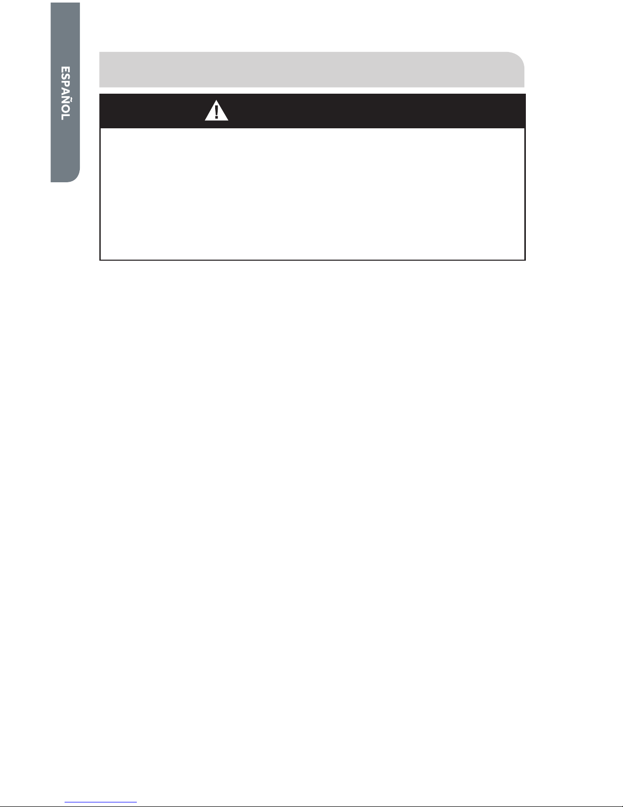
74
INSTRUCCIONES DE INSTALACIÓN
ADVERTENCIA
Riesgo de incendio
La instalación de la secadora de ropa debe estar a cargo de un
instalador competente.
Instale la secadora de ropa según las instrucciones del fabricante y los
códigos locales.
Para reducir el riesgo de lesiones severas o la muerte, siga todas las
instrucciones de instalación.
IMPORTANTE: Cuando descarte o guarde su vieja secadora de ropa, quítele
la puerta.
HERRAMIENTAS NECESARIAS
• Destornillador Phillips
• Destornillador de hoja plana
• Pinzas de articulación regulables
• Llave de extremo abierto de ½"
• Nivel de carpintero
• Cinta de medir (de 12 pies [3,7 m] mín.)
Solamente para las instalaciones a gas:
• Llave para tubos
• 2 llaves ajustables
PIEZAS ADICIONALES REQUERIDAS
• Tubería de escape de metal rígido o ß exible de 4" (10,2 cm)
• Abrazaderas para ducto
• Cinta para tubos
• Cable eléctrico (solamente para la secadora eléctrica de EE.UU.)
- Deberá comprarse un juego de cable de suministro eléctrico que satisfaga
los códigos eléctricos locales. Deberá usarse para la secadora un cable de
suministro eléctrico de 3 ó 4 hilos tipo NEMA 14-30 o 10-30, SRDT o ST
(según se necesite) de 120/240 voltios CA como mínimo, 30 amperios,
con 3 conectores de horquilla con extremos abiertos, con los extremos
hacia arriba o conectores con lazo cerrado, marcados para ser usados con
secadoras de ropa.
- Protector de cables que esté en la lista de UL
• Piezas para la conexión a gas (solamente para la secadora a gas)
- Codo NPT de "
- Accesorio adaptador abocinado NPT de "
- Conector de gas ß exible de "
- Compuesto para unión de tuberías
• Juego para la instalación en casas rodantes (solamente para las secadoras a gas
de casas rodantes)
Page 77

75
REQUISITOS DE UBICACIÓN
ADVERTENCIA
No instale la secadora en lugares donde se guarda o se almacena
gasolina u otros productos inflamables. Si se instala la secadora en un
garage, deberá estar a un mínimo de 18 pulgadas (45,7 cm) por encima
del piso. No seguir estas instrucciones puede ocasionar la muerte,
explosión, incendio o quemaduras.
• La secadora deberá instalarse sobre un piso sólido. El piso de hormigón es el
mejor.
• El piso deberá estar nivelado con un declive máximo de 1” (2,5 cm) debajo de
toda la secadora.
• Un lugar apropiado, protegido de la luz directa del sol y de fuentes de calor, tales
como radiadores, zócalos radiantes o aparatos de cocción.
• No la instale sobre una alfombra.
• La ubicación deberá tener contactos apropiados para el suministro eléctrico y
de gas. Consulte la sección “Requisitos del suministro eléctrico y de gas” para
obtener detalles.
• No instale la secadora en un área donde esté en contacto con cortinas, alfombras
pesadas o cualquier cosa que pudiera obstruir el ß ujo de aire para la combustión
y la ventilación.
DIMENSIONES DE LA SECADORA
27"
(68,6 cm)
30
¼"
(77,7 cm)
42½"
(108,0 cm)
Page 78
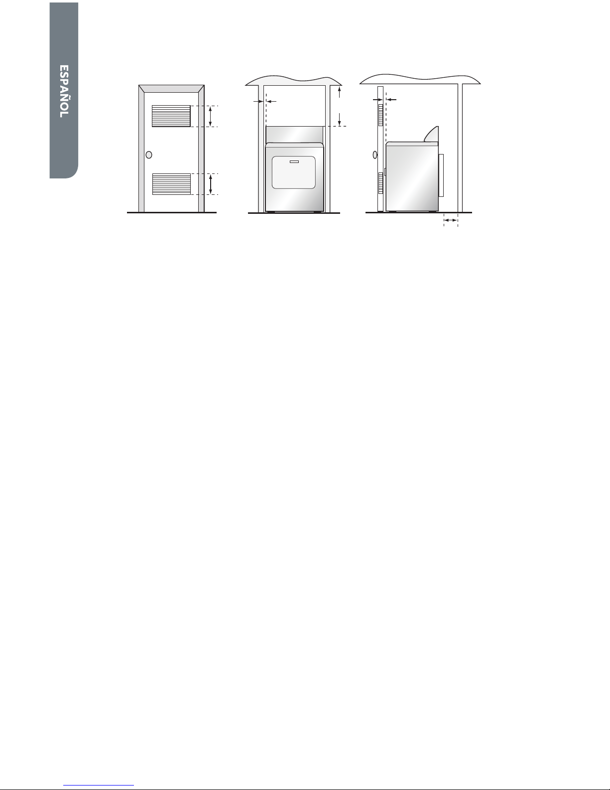
76
REQUISITOS PARA ALCOBAS O CLÓSETS
60 pulg.
2
(387,1 cm2)
60 pulg.
2
(387,1 cm2)
1"
(2,5 cm)
15"
(38,1 cm)
1"
(2,5 cm)
5½"
(14 cm)
ESPACIOS MÍNIMOS
• Las dimensiones que se muestran son los espacios mínimos recomendados
permitidos.
• Se necesita que haya espacio a los lados de la secadora para evitar la
transferencia de ruido.
• Será necesario que haya espacio en la parte posterior de la secadora para
colocar la tubería de escape.
OTROS REQUISITOS
• Esta secadora deberá ventilarse al exterior.
• No instale la secadora en un clóset con una puerta maciza.
• La puerta del clóset deberá tener rejillas u oriÞ cios de ventilación con una
abertura mínima de 120 pulg.² (774,2 cm²), dividida en partes iguales en la parte
superior e inferior de la puerta. No deberá obstruirse el ß ujo de aire de ningún
modo.
• No se debe instalar ningún otro electrodoméstico que use combustible en el
mismo clóset en el que se encuentra la secadora a gas.
Page 79

77
REQUISITOS DEL SUMINISTRO ELÉCTRICO Y DE GAS
SECADORA ELÉCTRICA (SOLAMENTE PARA EE.UU.)
ADVERTENCIA
La secadora deberá enchufarse en un contacto eléctrico debidamente
puesto a tierra, de 3 o 4 hilos, monofásico, de 120/240 voltios (o de
120/208 voltios), 60 Hz, CA solamente, conectado a un circuito
individual de 30 amperios con fusible, con un cortacircuitos o fusible
retardador de 30 amperios. No ponga a funcionar una lavadora y una
secadora en el mismo circuito.
ADVERTENCIA
Este aparato debe estar conectado a tierra. En caso de que se produzca
un cortocircuito, la conexión a tierra reduce el riesgo de choque
eléctrico al proporcionar una ruta de escape para la corriente eléctrica.
NOTA: El suministro eléctrico de la secadora deberá cumplir con los códigos y
ordenanzas locales, y la última edición del Código nacional eléctrico (National
Electrical Code), ANSI/NFPA 70.
• Si el suministro eléctrico que hay disponible en la ubicación deseada para la
secadora no satisface los requisitos mencionados anteriormente, póngase en
contacto con un electricista competente con licencia.
• Una secadora que funciona con un suministro eléctrico de 208 voltios demorará
más tiempo para secar que si estuviera funcionando con un suministro eléctrico
de 240 voltios.
• La secadora no ha sido equipada con un cable eléctrico. Deberá comprarse por
separado un juego que satisfaga los códigos eléctricos locales. Puede usarse
para la secadora un cable de suministro eléctrico de 3 o 4 hilos tipo NEMA 14-30
o 10-30, SRDT o ST (según se necesite) de 120/240 voltios CA como mínimo,
30 amperios, con 3 conectores de horquilla con extremos abiertos, con los
extremos hacia arriba o conectores con lazo cerrado, marcados para ser usado
con secadoras de ropa.
• Deberá sujetarse a la secadora un protector de cables que esté en la lista de UL
para sostener el cable eléctrico.
• No use un receptáculo de alambres de aluminio con un cable y enchufe con hilos
de cobre (o viceversa). La combinación apropiada de cableado y receptáculo
deberá ser un cable eléctrico con hilos de cobre con un receptáculo con hilos de
cobre.
• El contacto eléctrico deberá estar ubicado de modo que el cable esté accesible
cuando la secadora esté instalada en su sitio.
Page 80

78
SECADORA ELÉCTRICA (EN CANADÁ SOLAMENTE)
ADVERTENCIA
La secadora deberá enchufarse en un contacto eléctrico debidamente
puesto a tierra, de 4 hilos, monofásico, de 120/240 voltios, 60 Hz, CA
solamente, conectado a un circuito individual de 30 amperios con
fusible, con un cortacircuitos o fusible retardador de 30 amperios. No
ponga a funcionar una lavadora y una secadora en el mismo circuito.
ADVERTENCIA
Este aparato debe estar conectado a tierra. En caso de que se produzca
un cortocircuito, la conexión a tierra reduce el riesgo de choque
eléctrico al proporcionar una ruta de escape para la corriente eléctrica.
NOTA: El servicio eléctrico a la secadora deberá hacerse conforme a los códigos y
ordenanzas locales, y la última edición del Código eléctrico canadiense (Canadian
Electrical Code), CSA C22.1, parte 1.
• Si el suministro eléctrico que hay disponible en la ubicación deseada para la
secadora no satisface los requisitos mencionados anteriormente, póngase en
contacto con un electricista competente con licencia.
• No use un receptáculo de alambres de aluminio con un cable y enchufe con hilos
de cobre (o viceversa). La combinación apropiada de cableado y receptáculo
deberá ser un cable eléctrico con hilos de cobre con un receptáculo con hilos de
cobre.
• El contacto eléctrico deberá estar ubicado de modo que el cable esté accesible
cuando la secadora esté instalada en su sitio.
SECADORA A GAS
REQUISITOS DEL SUMINISTRO ELÉCTRICO
ADVERTENCIA
La secadora a gas deberá enchufarse en un contacto eléctrico
debidamente puesto a tierra, de 3 hilos, monofásico, de 120 voltios,
60 Hz, CA solamente, con un cortacircuitos o fusible retardador de
15 amperios.
Page 81

79
ADVERTENCIA
Este aparato debe estar conectado a tierra. En caso de que se produzca
un cortocircuito, la conexión a tierra reduce el riesgo de choque
eléctrico al proporcionar una ruta de escape para la corriente eléctrica.
• La secadora viene equipada con un cable eléctrico dotado de un enchufe de 3
terminales. No corte ni quite la terminal de puesta a tierra del enchufe.
• El cable eléctrico deberá ser enchufado en un contacto apropiado de 3
terminales, conectado a tierra de acuerdo con todos los códigos y ordenanzas
locales. Si no hay un contacto adecuado, comuníquese con un electricista con
licencia para que instale uno.
• Si usted no está seguro de que el contacto esté debidamente conectado a tierra,
comuníquese con un electricista con licencia.
• No use un adaptador para cable de 3 terminales.
• No use un cable eléctrico de extensión.
REQUISITOS DEL SUMINISTRO DE GAS
NOTA: El servicio de gas a la secadora deberá hacerse de acuerdo con los códigos
y ordenanzas locales y la última edición del Código nacional de gas combustible
(National Fuel Gas Code), ANSI Z223.1 o, en Canadá, CAN/CGA B149.1.
Gas natural
• La secadora está equipada para uso con gas natural.
Gas LP (Propano líquido)
• La secadora puede convertirse para usarse con gas LP.
• La conversión a gas LP deberá llevarla a cabo un técnico de gas competente.
Línea de suministro de gas
• La línea de suministro de gas deberá ser un tubo de ½" (1,3 cm) y deberá tener
una válvula de cierre individual manual instalada a menos de 6 pies (183 cm) de
la secadora, según el Código nacional de gas combustible (National Fuel Gas
Code), ANSI Z223.1/NFPA 54, o, en Canadá, con el Código para la instalación de
gas natural y propano (Natural Gas and Propane Installation Code), B149.1.
• La válvula de cierre deberá estar donde se pueda alcanzar con facilidad para
cerrarla y abrirla.
Page 82

80
• Se debe instalar una derivación tapada NTP de por lo menos !", accesible para
las pruebas de calibre, inmediatamente por encima de la conexión de suministro
de gas a la secadora.
• La línea de suministro debe terminar con un accesorio adaptador abocinado NPT
de ".
Línea de suministro de gas NPT de ½"
Válvula de cierre del gas
Derivación tapada NPT de !" como
mínimo
Accesorio adaptador abocinado NPT
de "
B
C
D
A
REQUISITOS PARA LA CONEXIÓN DEL SUMINISTRO
DE GAS
Esta secadora debe conectarse a la línea de suministro de gas con un conector
aprobado de gas ß exible que cumpla con las normas para conectores de
electrodomésticos a gas, ANSI Z21.24 o CSA 6.10.
Conector de gas ß exible de acero inoxidable:
• Si los códigos locales lo permiten, use un conector de gas ß exible nuevo de
acero inoxidable (diseño certiÞ cado por la Asociación estadounidense de gas o
CSA International), para conectar su secadora a la línea rígida de suministro de
gas. Use un codo y un accesorio adaptador abocinado NPT de ” por ” entre
el tubo de acero inoxidable y el tubo de gas de la secadora, para evitar que se
doblen.
REQUISITOS DE ENTRADA DEL QUEMADOR
Elevaciones de hasta 10.000 pies (3.048 m):
• El diseño de esta secadora está certiÞ cado por CSA Internacional para uso
en altitudes que alcanzan los 10.000 pies (3.048 m) sobre el nivel del mar en
la categoría de B.T.U. indicada en la placa del número de modelo/serie. No se
requieren ajustes de la entrada del quemador cuando se usa la secadora hasta
esta altitud.
Elevaciones por encima de 10.000 pies (3.048 m):
• Si se instala la secadora a un nivel superior a los 10.000 pies (3.048 m) de altitud,
se requiere una reducción de categoría de B.T.U. del 4% del quemador, que se
muestra en la placa del número de modelo/serie, por cada incremento de
1.000 pies (305 m) de altitud.
Prueba de presión del suministro de gas:
• Durante pruebas de presión a presiones mayores de ½ lb/pulg.² (3,5 kPa), la
secadora debe ser desconectada de la tubería del suministro de gas.
Page 83

81
REQUISITOS DEL SISTEMA DE ESCAPE
ADVERTENCIA
En esta sección se describen los requisitos para un sistema de escape
seguro y eficaz. No seguir estas instrucciones puede ocasionar un
rendimiento de secado insatisfactorio, daños a la secadora y peligro de
incendio.
IMPORTANTE: La secadora deberá ventilarse al exterior.
• La secadora no debe tener salida de escape a ningún ducto de escape de gas,
chimenea, pared, techo u otro espacio oculto de un ediÞ cio.
TUBERÍA
• Si el sistema de escape actual ha sido construido con un ducto de plástico o
metal de hoja ß exible, reemplácelo con un ducto de metal rígido.
• Use solamente un ducto de metal rígido de 4" (10,2 cm) de diámetro.
• Cuando haga giros en la tubería, use codos de 45° en vez de 90°. Esto provee
un mejor ß ujo de aire y puede reducir la acumulación de pelusa en el sistema de
escape.
90° - Bueno 45° - Mejor
• No exceda la longitud del ducto para el número de codos que se muestran en
la tabla a continuación. El hacerlo puede ocasionar acumulación de pelusa,
aumentar el tiempo de secado y crear un riesgo de incendio.
• Dos codos de 45° equivalen a un codo de 90°.
Page 84

82
Longitud máxima recomendada de escape
Tipos de capota de ventilación
Se recomienda Use solamente para las
instalaciones de tendido
corto
4"
(10,2 cm)
4"
(10,2 cm)
de diámetro
4"
(10,2 cm)
de diámetro
2½"
(6,4 cm)
4"
(10,2 cm)
de diámetro
N° de codos de 90° Metal rígido Metal rígido
0
1
2
3
90 pies
60 pies
45 pies
35 pies
60 pies
45 pies
35 pies
25 pies
• Todas las uniones deberán estar ajustadas para evitar fugas. El extremo macho
de cada sección de la tubería deberá estar dirigido lejos de la secadora.
• Utilice abrazaderas o cinta para ductos para conectar
y sellar todas las uniones. No las conecte con tornillos
ni otros sujetadores que se extiendan en el interior del
tubo, ya que crearán un punto en donde se acumulará
la pelusa.
Abrazadera
• Evite dirigir el sistema de escape a través de un área sin calor, ya que esto hará
que se forme condensación en el interior del ducto y aumentará la acumulación
de pelusa.
• Evite dirigir el sistema de escape en forma vertical a través del techo, ya que
esto puede exponer el sistema de escape a corrientes de aire descendentes,
ocasionando una mayor restricción de aire.
• Evite que el sistema de escape se doble, se comprima o se pliegue, ya que esto
hará que se reduzca el ß ujo de aire y ocasionará un rendimiento insatisfactorio de
secado.
• No ponga un Þ ltro en el extremo del sistema de escape. Se acumulará pelusa y
con el tiempo obstruirá el Þ ltro. Use una capota de ventilación aprobada para
terminar el ducto en el exterior.
Page 85

83
CAPOTA DE VENTILACIÓN
• Use una capota de ventilación aprobada con una compuerta que se abra hacia
fuera cuando la secadora esté funcionando. Cuando se detenga la secadora,
la compuerta se cerrará automáticamente para evitar corrientes de aire y la
entrada de insectos y roedores.
• Se recomiendan las capotas de ventilación estilo persiana o estilo caja. Son
aceptables las capotas de estilo angular, pero deberán usarse solamente para
las instalaciones con un tendido corto. Consulte la tabla “Longitud máxima
recomendada de escape” para obtener más información.
• Para evitar restringir el ß ujo de aire, mantenga un espacio mínimo de 12"
(30,5 cm) entre la capota de ventilación y el piso u otra obstrucción.
REQUISITOS ADICIONALES PARA LAS CASAS
RODANTES
• La instalación deberá hacerse conforme al Estándar para la construcción y
seguridad de hogares manufacturados (Manufactured Home Construction
and Safety Standard), Título 24 CFR-Parte 3280 o el Estándar canadiense para
los hogares manufacturados (Canadian Manufactured Home Standard), CAN/
CSA-Z240 MH.
• Deberán tomarse medidas especiales para el aire exterior de complemento. La
abertura deberá ser, por lo menos, dos veces más grande que la salida de escape
de la secadora.
• Si se ventila la secadora a través del piso y dentro de un área encerrada debajo
de la casa rodante, el sistema de escape deberá terminar en el exterior del
recinto, con la terminación bien asegurada a la estructura de la casa rodante.
SOLAMENTE PARA LA SECADORA A GAS
(SOLAMENTE PARA CASAS RODANTES)
• La secadora deberá asegurarse al piso usando un juego para la instalación en
casas rodantes. Siga las instrucciones provistas con el juego.
Page 86

84
INSTRUCCIONES PASO A PASO
INSTALACIÓN DE LA SECADORA
Se recomienda que su nueva secadora sea instalada por un técnico de aparatos
competente. Si le parece que tiene la habilidad para instalar la secadora, lea las
instrucciones detalladamente antes de hacerlo.
CUIDADO: Si después de seguir estos pasos no está seguro de haber instalado
la secadora adecuadamente, póngase en contacto con un técnico de aparatos
competente.
PASO 1 – DESEMPAQUE LA SECADORA
1. Quite todos los materiales de empaque. Esto incluye la base de espuma y toda
la cinta adhesiva que mantiene sujetos adentro y afuera los accesorios de la
secadora.
2. Inspeccione y quite los restos de materiales de empaque, cinta o material
impreso antes de usar la secadora.
ADVERTENCIA
Para evitar el peligro de asfixia, mantenga la bolsa de plástico y otros
materiales de empaque lejos del alcance de bebés y niños. No use esta
bolsa en cunas, cochecitos ni corrales. La bolsa de plástico podría
bloquear la nariz y la boca, impidiendo la respiración. Esta bolsa no es un
juguete.
PASO 2 – CONECTE UN CABLE ELÉCTRICO A LA
SECADORA (SECADORA ELÉCTRICA - SOLAMENTE
PARA EE.UU.)
1. Quite el tornillo que asegura la cubierta de acceso del bloque de terminal,
ubicada en la parte posterior de la esquina superior de la secadora.
Cubierta de acceso del bloque de
terminal
OriÞ cio en el soporte de montaje
del protector de cables
Tornillo de la cubierta de acceso
A
B
C
Page 87

85
2. Inserte un protector de cables que esté en la lista de UL en el oriÞ cio del soporte
de montaje. Coloque el protector de cables de modo que una lengüeta esté
mirando hacia arriba y la otra mirando hacia abajo. Ajuste los tornillos del
protector de cables sólo lo suÞ ciente para mantener las dos mitades juntas.
Lengüeta
Protector de cables
A
B
3. Inserte el cable eléctrico en el protector de cables. Asegúrese de que el
aislamiento de cables del cable eléctrico esté dentro del protector de cables.
4. Conecte los alambres del cable eléctrico siguiendo la Parte A para la
conexión del cable eléctrico de 4 hilos o la Parte B para la conexión del
cable eléctrico de 3 hilos.
4 hilos (se recomienda) si su hogar tiene un receptáculo de 4 hilos
(tipo NEMA 14-30, SRDT o ST):
3 hilos (si no hay disponible un alambre de 4 hilos) si su hogar tiene un
receptáculo de 3 hilos (tipo NEMA 10-30 SRDT):
CUIDADO: Se necesita una conexión de 4 hilos para las casas
rodantes y donde los códigos locales no permitan el uso de
conexiones de 3 hilos.
5. Ajuste los tornillos del protector de cables.
6. Cerciórese de que ninguno de los cables toquen el tambor de la secadora en el
interior del gabinete de la secadora.
7. Vuelva a colocar la cubierta del bloque de terminal.
Page 88

86
PARTE A – CABLE ELÉCTRICO DE 4 HILOS
A
B
C
F
E
G
D
Tornillo a tierra (verde)
Tornillo del bloque de terminal
Hilo de puente de conexión a
neutro (verde)
Hilo a tierra del cable eléctrico
(verde)
Hilo neutro del cable eléctrico
(blanco)
Hilos de la línea del cable eléctrico
(uno rojo y uno negro)
Cable eléctrico
A1. Quite el tornillo verde a tierra que conecta el hilo de puente de conexión a neutro
(verde) al gabinete y el tornillo central del bloque de terminal; deseche el hilo de
puente.
A2. Sujete el hilo a tierra del cable eléctrico (verde) al gabinete con el tornillo verde a
tierra. Ajuste Þ rmemente el tornillo.
A3. Sujete el hilo neutro del cable eléctrico (blanco) al tornillo central del bloque de
terminal. Ajuste Þ rmemente el tornillo.
A4. Sujete los 2 hilos restantes (rojo y negro) de la línea del cable eléctrico a los
tornillos externos del bloque de terminal. Sujete un hilo a cada bloque de
terminal, como se muestra. Ajuste Þ rmemente ambos tornillos.
IMPORTANTE: No doble ni pliegue demasiado los hilos en las conexiones.
Page 89

87
PARTE B – CABLE ELÉCTRICO DE 3 HILOS
A
B
C
E
D
F
Tornillo a tierra (verde)
Tornillo del bloque de terminal
Hilo de puente de conexión a
neutro (verde)
Hilo neutro del cable eléctrico
(blanco)
Hilos de la línea del cable eléctrico
(uno rojo y uno negro)
Cable eléctrico
B1. Sujete el hilo neutro del cable eléctrico (blanco) al tornillo central del bloque de
terminal. Ajuste Þ rmemente el tornillo.
B2. Sujete los 2 hilos restantes (rojo y negro) de la línea del cable eléctrico a los
tornillos externos del bloque de terminal. Sujete un hilo a cada bloque de
terminal, como se muestra. Ajuste Þ rmemente ambos tornillos.
IMPORTANTE: No doble ni pliegue demasiado los hilos en las conexiones.
PASO 2 – CONECTE A UNA LÍNEA DE SUMINISTRO DE GAS
(SOLAMENTE PARA LA SECADORA A GAS)
NOTA: No conecte la secadora a una línea de gas LP sin antes convertir la secadora
con un juego de conversión. Un juego de conversión a gas LP deberá ser instalado
por un técnico competente.
NOTA: Aplique un compuesto para uniones de tubería que sea resistente a la acción
del gas LP a todas las roscas macho. No use cinta para plomería.
1. Cierre el suministro de gas moviendo la válvula de cierre hacia la posición
cerrada.
Válvula cerrada
Válvula abierta
A
B
2. Desconecte y deseche el conector ß exible de gas viejo. Reemplácelo con un
nuevo conector ß exible de gas aprobado por CSA (AGA).
3. Quite la cubierta de transporte del tubo de entrada de gas en la parte posterior
de la secadora.
Page 90

88
4. Conecte un codo NPT de " al tubo de entrada de gas en la secadora. Luego
conecte un adaptador abocinado al codo.
IMPORTANTE: Use una llave para tubos para evitar que se tuerza el tubo de
entrada de gas de la secadora.
Tubo de entrada de
gas en la secadora
Codo NPT de "
Adaptador abocinado NPT
de "
A
B
C
5. Conecte la secadora a la línea de suministro de gas con un conector ß exible de
gas.
Conector ß exible de gas
A
6. Ajuste el conector ß exible de gas con dos llaves ajustables.
7. Abra el suministro de gas moviendo la válvula de cierre hacia la posición abierta.
La válvula está abierta cuando la manija está paralela al tubo de gas.
8. Revise todas las conexiones para ver si tienen fugas, aplicando una solución de
detección de fugas que no sea corrosiva. Se observarán burbujas si hay fugas. Si
se encuentran fugas, cierre la válvula de cierre, vuelva a ajustar la unión, abra la
válvula de cierre y revise nuevamente.
ADVERTENCIA
Nunca use una llama abierta para revisar si hay fugas de gas.
Page 91

89
PASO 3 – CONECTE A UN SISTEMA DE ESCAPE
ADVERTENCIA
Para reducir el riesgo de incendio, esta secadora debe ventilarse hacia
el exterior.
1. Cerciórese de que el sistema de escape esté libre y despejado de acumulación
de pelusa antes de conectar la secadora.
2. Use un ducto de metal rígido o ß exible de 4" (102 mm) para conectar la salida de
escape de la secadora al sistema de escape.
3. Utilice abrazaderas para sellar y asegurar todas las juntas. No debe conectarse
ni asegurarse el ducto de escape con tornillos ni con ningún otro dispositivo de
sujeción que se extienda hacia el interior de dicho ducto.
NOTAS:
• No utilice un ducto de escape de plástico ni de metal de hoja ß exible. Es posible
que se acumule exceso de pelusa dentro de la tubería, restringiendo el ß ujo de
aire y creando un riesgo de incendio. La restricción en el ß ujo de aire aumentará
el tiempo de secado.
• La secadora no debe tener salida de escape a ningún ducto de escape de gas,
chimenea, pared, techo u otro espacio oculto de un ediÞ cio. La secadora deberá
ventilarse al exterior. Si la secadora no se ventila al exterior, expulsará un poco
de pelusa Þ na dentro del área del lavadero. Una acumulación de pelusa en
cualquier área del hogar puede ocasionar un peligro para la salud y un riesgo de
incendio.
Page 92

90
PASO 4 – NIVELE LA SECADORA
1. Coloque la secadora en su ubicación Þ nal. Tenga cuidado de no aplastar ni
retorcer el ducto de escape. Cerciórese de que las cuatro patas estén en
contacto Þ rme con el piso y que la secadora descanse Þ rmemente en su sitio.
NOTA: Para una secadora a gas, cerciórese de que la línea de gas ß exible no esté
retorcida.
2. Con un nivel de carpintero, cerciórese de que la secadora esté nivelada de lado a
lado y de frente hacia atrás.
3. Si la secadora no está nivelada, regule las patas niveladoras. Gírelas hacia la
derecha para extender (levantar la secadora) o hacia la izquierda para retraer
(bajar la secadora).
PASO 5 – COMPLETE LA INSTALACIÓN
1. Enchufe el cable eléctrico de la secadora en el contacto apropiado.
2. Vuelva a conectar la energía al contacto. Asegúrese de que el cortacircuitos esté
activado.
3. Deshágase de todos los materiales de empaque o recíclelos.
4. Cerciórese de que el área de la secadora esté limpia y sin materiales
combustibles, gasolina y otros vapores inß amables. También asegúrese de
que ningún objeto (por ejemplo, cajas, ropa, etc.) obstruya el ß ujo de aire para
la combustión y la ventilación a través del panel con rejillas ubicado en la parte
posterior de la secadora.
5. Pruebe el funcionamiento de la secadora seleccionando un ciclo de Timed Dry
(Secado programado) con calor. Consulte la sección “Instrucciones para el
funcionamiento”.
NOTA: En las secadoras a gas, antes de que se encienda el quemador, será necesario
extraer el aire de la línea de gas. Si el quemador no se enciende en menos de
45 segundos cuando se encienda la secadora por primera vez, el interruptor de
seguridad apagará el quemador. Si esto sucede, apague (girando hacia “OFF”) la
secadora y espere 5 minutos antes de hacer otro intento de encender el quemador.
Page 93

91
PANEL DE CONTROL Y CARACTERÍSTICAS
PANEL DE CONTROL
H
I
G
H
-
L
O
W
-
O
F
F
Timed Dry Adjust
Cycle
Signal
Damp
Signal
More
Normal
Less
Medium
Low
Extra Low
No Heat
150 Min
60 Min
Cycle
Status
POWER
High
Heavy
Duty
Eco Dry
Perm
Press
Delicate
Sanitize
Air Dry
Touch Up
Quick
Dry
Timed Dry
NormalN
ormal
AUTOMATIC C YCLES
TIMED DRY CYCLES
Drying
Cool Down
Wrinkle Saver
Clean Lint
T
I
M
E
D
D
R
Y
O
N
L
A
U
T
O
C
Y
C
L
E
S
O
N
L
Y
o a
Normal
Dry
Dry
Temp
Wrinkle
Saver
Level
ESTIMATED TIME REMAINING
A
B
C
D
E
F
G
H
I
J
K
INDICADORES DEL ESTADO DEL CICLO
• Cuando se haya puesto en marcha la secadora por primera vez, las luces de
Cycle Status (Estado del ciclo) indicarán las etapas del ciclo seleccionado.
• Cuando la secadora está en funcionamiento, destella la luz de la etapa
activa. A medida que se completa cada etapa, la luz se apagará y comenzará
a destellar la etapa siguiente.
• El ciclo de secado se ha terminado por completo cuando se apaguen todas
las luces.
• El indicador Clean Lint (Limpiar Þ ltro de pelusa) destellará cuando se
enciende la secadora para recordarle que tiene que limpiar el Þ ltro de pelusa.
Se apagará cuando comience un ciclo seco.
BOTÓN POWER (ENCENDIDO)
• Use este botón para encender y apagar la secadora.
NOTA: Si la secadora está encendida, pero no se ha puesto en marcha, se
apagará automáticamente después de 5 minutos.
BOTÓN DRY LEVEL (NIVEL DE SECADO)
• Use este botón para ajustar el nivel de secado de los programas de ciclo
automático.
NOTA: Este botón sólo funciona con ciclos automáticos.
Page 94

92
PERILLA DE SELECCIÓN DE CICLOS
• Hay 6 ciclos automáticos para elegir:
Sanitize (Higienizar): Use este ciclo para ayudar a higienizar prendas tales
como toallas, ropa de cama y ropa de los niños. Es conveniente ejecutar este
ciclo hasta completarse.
Heavy Duty (Intenso): Use este ciclo para el calor a alta temperatura con
telas pesadas como toallas y pantalones de mezclilla.
Normal - Use este ciclo para calor a temperatura media con prendas de
algodón y lino.
Eco Dry (Secado ecológico): Use este ciclo para ahorrar energía. Este
programa es similar al Normal, pero emplea una temperatura levemente
inferior y seca a un nivel de secado levemente inferior.
Perm Press (Planchado permanente): Use este ciclo para calor a baja
temperatura con telas que no desee que se arruguen.
Delicate (Delicado): Use este ciclo para calor muy bajo para secar prendas
delicadas.
• Hay 4 ciclos de secado programado para elegir:
Timed Dry (Secado programado): Use este ciclo para hacer funcionar la
secadora durante una cantidad de tiempo especíÞ ca. Las prendas pueden
quedar húmedas o demasiado secas al Þ nal del ciclo.
Quick Dry (Secado rápido): Use este ciclo para seleccionar con facilidad un
ciclo de 20 minutos para secar rápidamente algunas prendas.
Touch Up (Retoque): Use este ciclo para seleccionar con facilidad un ciclo de
10 minutos para refrescar las prendas limpias.
Air Dry (Secado al aire): Use este ciclo para secar espuma, goma, plástico o
telas sensibles al calor.
BOTÓN START/PAUSE (INICIO/PAUSA)
• Presione este botón para poner en marcha un ciclo seleccionado o hacer
una pausa en un ciclo que esté en marcha.
NOTA: Después de iniciar el ciclo de secado, debe hacer una pausa en la
secadora si desea cambiar alguna de las opciones.
NOTA: La apertura de la puerta de la secadora también hará una pausa en el
ciclo que esté en marcha.
NOTA: Si el estado del ciclo es Wrinkle Saver (Antiarrugas), al pesionar el
botón de pausa o abrir la puerta de la secadora, se cancelará el ciclo que esté
en marcha y la secadora se apagará completamente.
BOTÓN DRY TEMP (TEMPERATURA DE SECADO)
• Utilice este botón para seleccionar una temperatura de secado. Para
obtener mejores resultados, siga las instrucciones de la etiqueta de las
prendas y use la temperatura más caliente que la tela pueda resistir.
NOTA: Este botón sólo funciona con ciclos de secado programado. El ajuste
No Heat (Sin calor) no está disponible cuando utiliza un ciclo automático.
Page 95

93
BOTÓN WRINKLE SAVER (ANTIARRUGAS)
• Al Þ nal del ciclo de enfriamiento, la secadora dará vueltas la carga durante
1 hora para evitar que se formen arrugas en las prendas. Utilice este botón
para extender la función durante 150 minutos o para apagar la función
Wrinkle Saver (Antiarrugas).
PANTALLA DE TIEMPO ESTIMADO RESTANTE
• Esta pantalla muestra el tiempo total estimado de un ciclo de secado en
minutos. Cuando la secadora está en funcionamiento, la pantalla hará la
cuenta regresiva en minutos para mostrar el tiempo restante.
• Si la secadora detecta un mal funcionamiento, se mostrará un código de
error en la pantalla. Consulte la sección “Solución de problemas” para
obtener una lista de códigos de error y sus posibles causas y soluciones.
BOTONES TIMED DRY ADJUST
(AJUSTE DE SECADO PROGRAMADO)
• Use estos botones para ajustar la duración de un ciclo de secado
programado. El tiempo se puede ajustar de 10 a 95 minutos en incrementos
de 5 minutos.
NOTA: Si el estado del ciclo es Cool Down (ciclo de enfriamiento), no se
puede ajustar el tiempo.
BOTÓN CYCLE SIGNAL (SEÑAL DE CICLO)
• Use este botón para ajustar el volumen de los sonidos del panel de control y
la señal de Þ n de ciclo.
BOTÓN DAMP SIGNAL (SEÑAL DE HÚMEDO)
• Use este botón para seleccionar o anular la selección del botón Damp
Signal (Señal de húmedo). Esta función le alertará cuando su ropa esté
aproximadamente 80% seca. Esto es útil cuando desea quitar artículos
parcialmente secos que quisiera planchar. Además le permite desenredar y
redistribuir los artículos grandes y voluminosos antes de Þ nalizar el ciclo.
NOTA: Aunque la señal del ciclo esté apagada, la señal de húmedo sonará.
Page 96

94
GUÍA DE CICLOS
NOTA: Para proteger sus prendas, no todas las opciones y los ajustes están
disponibles con todos los ciclos. Las cajas sombreadas indican los ajustes por
defecto para cada ciclo.
CICLO TIPO DE TELA
DURACIÓN
EST.
TEMPERATURA
DE SECADO
NIVEL DE
SECADO
OPTIONS
(Opciones)
Sanitize
(Higienizar)
Toallas, ropa de
cama, ropa para
niños
70 High (Alta)
More
(Más)
Wrinkle Saver
(Antiarrugas)
Damp Signal
(Señal de húmedo)
Heavy
Duty
(Intenso)
Artículos pesados
como toallas y
pantalones de
mezclilla
45
High (Alta)
Normal
Wrinkle Saver
(Antiarrugas)
Damp Signal
(Señal de húmedo)
More
(Más)
Less
(Menos)
Normal
Telas de algodón,
lino y prendas
mezcladas
42
Medium (Media)
Normal
Wrinkle Saver
(Antiarrugas)
Damp Signal
(Señal de húmedo)
More
(Más)
Less
(Menos)
Eco Dry
(Secado
ecológico)
Telas de algodón,
lino y prendas
mezcladas
40
Medium (Media)
Normal
Wrinkle Saver
(Antiarrugas)
Damp Signal
(Señal de húmedo)
More
(Más)
Less
(Menos)
Perm Press
(Planchado
perma-
nente)
Mezclas de
algodón y
poliéster, camisas
y pantalones
antiarrugas
35
Low (Baja)
Normal
Wrinkle Saver
(Antiarrugas)
Damp Signal
(Señal de húmedo)
More
(Más)
Less
(Menos)
Delicate
(Ropa
delicada)
Lencería, blusas y
Þ bras sintéticas
28
Extra Low (Extra
baja)
Normal
Wrinkle Saver
(Antiarrugas)
Damp Signal
(Señal de húmedo)
More
(Más)
Less
(Menos)
Timed Dry
(Secado
progra-
mado)
Telas de algodón,
lino y prendas
mezcladas
40
Ajustable
(10 a 95)
Medium (Media)
N/A
Wrinkle Saver
(Antiarrugas)
High (Alta)
Low (Baja)
Extra Low
(Extra baja)
No Heat (Sin calor)
Quick Dry
(Secado
rápido)
Cargas pequeñas
y ropa deportiva
20
Ajustable
(10 a 95)
Medium (Media)
N/A N/A
High (Alta)
Low (Baja)
Extra Low
(Extra baja)
No Heat (Sin calor)
Touch Up
(Retoque)
Telas de algodón,
lino y prendas
mezcladas
10
Ajustable
(10 a 95)
Medium (Media)
N/A N/A
High (Alta)
Low (Baja)
Extra Low
(Extra baja)
No Heat (Sin calor)
Air Dry
(Secado al
aire)
Goma, plástico y
telas sensibles al
calor
40
Ajustable
(10 a 95)
No Heat
(Sin calor)
N/A N/A
Page 97

95
CARACTERÍSTICAS
SENSOR DE SEQUEDAD DE HUMEDAD
• El sensor de humedad permite a la secadora detectar el contenido real de
humedad de las prendas en la carga. Los ciclos automáticos utilizan esta
información junto con las lecturas de temperatura de aire para completar el ciclo
de secado en el momento apropiado. Esta tecnología inteligente ahorra energía,
reduce la estática y protege a las prendas de daños ocasionados por el secado
en exceso.
• El sensor además proporciona resultados de secado uniformes y precisos y le
permite realizar un ajuste Þ no del rendimiento de la secadora con el botón Dry
Level (Nivel de secado).
LUZ INTERNA DEL TAMBOR
• La luz interna del tambor le permite ver dentro de la secadora y encontrar todos
los artículos de lavado. El interruptor del gabinete enciende automáticamente la
luz cuando se abre la puerta y se apaga cuando ésta se cierra.
• Para obtener instrucciones detalladas acerca del cambio de la bombilla, consulte
la Guía para el cuidado y la limpieza.
Page 98

96
INSTRUCCIONES PARA EL FUNCIONAMIENTO
PASO 1 – PREPARE Y SEPARE LAS PRENDAS
• Revise las etiquetas de las prendas para ver las instrucciones de secado.
• Siempre que sea posible, dé vuelta los bolsillos para obtener un secado
uniforme.
• Ate los cordones y las fajas de modo que no se enreden.
• Cierre los zípers, broches de presión y corchetes para evitar que se enganchen.
• Cerciórese de que los botones y los adornos en las prendas sean resistentes a
temperaturas elevadas y que no dañen la superÞ cie del tambor.
• Para evitar que las manchas y la suciedad queden permanentemente en las
prendas, cerciórese de que se hayan quitado durante el ciclo de lavado. De no
ser así, lávelas de nuevo.
• Para evitar que las prendas se enreden y se puedan sacar con facilidad, los
artículos pequeños deberán ponerse juntos en una bolsa de malla antes de
ponerse a lavar.
• Separe las telas que atraen pelusa de las telas que sueltan pelusa. Las prendas
propensas a formar pelusa deberán darse vuelta de adentro hacia fuera antes de
colocarse en la secadora.
PASO 2 – LIMPIE EL FILTRO DE PELUSA
1. Limpie el Þ ltro de pelusa antes de cada uso. El Þ ltro puede quitarse jalando la
manija del Þ ltro de pelusa, que está ubicada dentro de la puerta de la secadora.
2. Enrolle con los dedos la pelusa acumulada para quitarla del Þ ltro de pelusa. No
enjuague ni lave el Þ ltro para quitar la pelusa.
3. Deslice el Þ ltro de pelusa de nuevo a su lugar.
NOTAS:
• No use la secadora sin el Þ ltro de pelusa en su lugar. Sin el Þ ltro de pelusa, las
prendas podrían entrar en el sistema de escape y provocar daños en la secadora.
• La pelusa acumulada en el Þ ltro hará que se restrinja el ß ujo de aire y ocasionará
tiempos de secado más prolongados.
Page 99

97
PASO 3 – CARGUE LA SECADORA
1. Cargue las prendas húmedas holgadamente en el tambor de la secadora.
2. Cierre la puerta de la secadora.
NOTAS:
• No ponga las prendas apretadas en la secadora.
• Una carga adecuada deberá tener 1/3 a 1/2 del volumen del tambor. Para
obtener un secado uniforme y sin que se formen arrugas, deje espacio para que
las prendas giren libremente.
• Cuando seque artículos grandes y voluminosos, deberá cargar solamente 2 a 3
piezas cada vez, junto con unas pocas prendas de tamaño pequeño y mediano.
• Para la ropa delicada o las cargas pequeñas, si agrega un par de toallas ayudará a
asegurar que las prendas giren. Con esto se obtendrá un secado uniforme y se
reducirán las arrugas.
PASO 4 – PONGA LA SECADORA EN MARCHA
1. Encienda la secadora presionando el BOTÓN POWER (Encendido).
2. Seleccione un ciclo de secado girando la PERILLA CYCLE SELECTION (Selección
de ciclos).
3. ModiÞ que los ajustes y las opciones por defecto, si lo desea.
4. Presione el BOTÓN START/PAUSE (Inicio/Pausa) que sobresale en la perilla para
poner la secadora en marcha.
NOTA:
• Si se abre la puerta, se hará una pausa en el ciclo que esté en marcha. Cierre la
puerta y presione el BOTÓN START/PAUSE (Inicio/Pausa) para reanudar.
Page 100

98
GUÍA PARA EL CUIDADO Y LA LIMPIEZA
ADVERTENCIA
Siempre desenchufe la secadora para evitar un choque eléctrico antes
de la limpieza.
El ignorar esta advertencia puede ocasionar la muerte o lesiones.
Antes de usar productos de limpieza, siempre lea y siga las
instrucciones del fabricante y las advertencias, para evitar lesiones
personales o al producto.
LIMPIEZA Y MANTENIMIENTO
• Utilice solamente un paño húmedo o jabonoso para limpiar el panel de control.
• Si derrama suavizante, blanqueador o detergente líquido o en polvo sobre el
gabinete, límpielo inmediatamente con un paño húmedo para evitar daños en el
acabado.
• No use productos de limpieza abrasivos, productos químicos irritantes,
amoníaco, blanqueador con cloro, detergente concentrado o solventes
para limpiar la secadora. Estos productos químicos pueden disolver, dañar o
decolorar la secadora.
• No use ningún tipo de limpiador con rociador cuando limpie el interior de la
secadora. Pueden producirse gases peligrosos o choque eléctrico. Si se mancha
la secadora, limpie el tambor con un paño húmedo. Quite los residuos que hayan
quedado antes de secar la próxima carga.
LAVADO DEL FILTRO DE PELUSA
• Los residuos de detergente y suavizante de telas pueden acumularse en el
Þ ltro de pelusa. Esta acumulación puede dar lugar a períodos más prolongados
de secado, o hacer que la secadora se detenga antes de que la ropa esté
completamente seca.
• Lave el Þ ltro de pelusa cada 6 meses o antes si se obstruye debido a la
acumulación de residuos.
Pasos para lavar el Þ ltro de pelusa:
1. Quite la acumulación normal de pelusa con los dedos.
2. Moje ambos lados del Þ ltro de pelusa con agua caliente.
3. Aplique detergente líquido con agua y refriegue con un cepillo de plástico.
4. Enjuague a fondo el Þ ltro de pelusa con agua caliente.
5. Seque por completo el Þ ltro de pelusa antes de volver a instalarlo y de usar la
secadora.
 Loading...